WO2022249557A1 - Planar illumination device - Google Patents
Planar illumination device Download PDFInfo
- Publication number
- WO2022249557A1 WO2022249557A1 PCT/JP2022/004402 JP2022004402W WO2022249557A1 WO 2022249557 A1 WO2022249557 A1 WO 2022249557A1 JP 2022004402 W JP2022004402 W JP 2022004402W WO 2022249557 A1 WO2022249557 A1 WO 2022249557A1
- Authority
- WO
- WIPO (PCT)
- Prior art keywords
- lens
- axial direction
- light
- surface facing
- illumination device
- Prior art date
Links
- 238000005286 illumination Methods 0.000 title claims abstract description 39
- 230000003287 optical effect Effects 0.000 claims abstract description 45
- 239000000758 substrate Substances 0.000 claims abstract description 30
- 230000000007 visual effect Effects 0.000 claims description 12
- 238000009792 diffusion process Methods 0.000 claims description 8
- 230000004048 modification Effects 0.000 description 48
- 238000012986 modification Methods 0.000 description 48
- 238000010586 diagram Methods 0.000 description 17
- 230000000694 effects Effects 0.000 description 4
- 230000000903 blocking effect Effects 0.000 description 2
- 238000001746 injection moulding Methods 0.000 description 2
- 239000004973 liquid crystal related substance Substances 0.000 description 2
- 239000000470 constituent Substances 0.000 description 1
- 238000006073 displacement reaction Methods 0.000 description 1
- 230000008030 elimination Effects 0.000 description 1
- 238000003379 elimination reaction Methods 0.000 description 1
- 239000011347 resin Substances 0.000 description 1
- 229920005989 resin Polymers 0.000 description 1
Images


Classifications
-
- G—PHYSICS
- G02—OPTICS
- G02F—OPTICAL DEVICES OR ARRANGEMENTS FOR THE CONTROL OF LIGHT BY MODIFICATION OF THE OPTICAL PROPERTIES OF THE MEDIA OF THE ELEMENTS INVOLVED THEREIN; NON-LINEAR OPTICS; FREQUENCY-CHANGING OF LIGHT; OPTICAL LOGIC ELEMENTS; OPTICAL ANALOGUE/DIGITAL CONVERTERS
- G02F1/00—Devices or arrangements for the control of the intensity, colour, phase, polarisation or direction of light arriving from an independent light source, e.g. switching, gating or modulating; Non-linear optics
- G02F1/01—Devices or arrangements for the control of the intensity, colour, phase, polarisation or direction of light arriving from an independent light source, e.g. switching, gating or modulating; Non-linear optics for the control of the intensity, phase, polarisation or colour
- G02F1/13—Devices or arrangements for the control of the intensity, colour, phase, polarisation or direction of light arriving from an independent light source, e.g. switching, gating or modulating; Non-linear optics for the control of the intensity, phase, polarisation or colour based on liquid crystals, e.g. single liquid crystal display cells
- G02F1/133—Constructional arrangements; Operation of liquid crystal cells; Circuit arrangements
- G02F1/1333—Constructional arrangements; Manufacturing methods
- G02F1/1335—Structural association of cells with optical devices, e.g. polarisers or reflectors
- G02F1/1336—Illuminating devices
- G02F1/133602—Direct backlight
- G02F1/133603—Direct backlight with LEDs
-
- F—MECHANICAL ENGINEERING; LIGHTING; HEATING; WEAPONS; BLASTING
- F21—LIGHTING
- F21S—NON-PORTABLE LIGHTING DEVICES; SYSTEMS THEREOF; VEHICLE LIGHTING DEVICES SPECIALLY ADAPTED FOR VEHICLE EXTERIORS
- F21S2/00—Systems of lighting devices, not provided for in main groups F21S4/00 - F21S10/00 or F21S19/00, e.g. of modular construction
-
- F—MECHANICAL ENGINEERING; LIGHTING; HEATING; WEAPONS; BLASTING
- F21—LIGHTING
- F21V—FUNCTIONAL FEATURES OR DETAILS OF LIGHTING DEVICES OR SYSTEMS THEREOF; STRUCTURAL COMBINATIONS OF LIGHTING DEVICES WITH OTHER ARTICLES, NOT OTHERWISE PROVIDED FOR
- F21V5/00—Refractors for light sources
- F21V5/04—Refractors for light sources of lens shape
-
- G—PHYSICS
- G02—OPTICS
- G02F—OPTICAL DEVICES OR ARRANGEMENTS FOR THE CONTROL OF LIGHT BY MODIFICATION OF THE OPTICAL PROPERTIES OF THE MEDIA OF THE ELEMENTS INVOLVED THEREIN; NON-LINEAR OPTICS; FREQUENCY-CHANGING OF LIGHT; OPTICAL LOGIC ELEMENTS; OPTICAL ANALOGUE/DIGITAL CONVERTERS
- G02F1/00—Devices or arrangements for the control of the intensity, colour, phase, polarisation or direction of light arriving from an independent light source, e.g. switching, gating or modulating; Non-linear optics
- G02F1/01—Devices or arrangements for the control of the intensity, colour, phase, polarisation or direction of light arriving from an independent light source, e.g. switching, gating or modulating; Non-linear optics for the control of the intensity, phase, polarisation or colour
- G02F1/13—Devices or arrangements for the control of the intensity, colour, phase, polarisation or direction of light arriving from an independent light source, e.g. switching, gating or modulating; Non-linear optics for the control of the intensity, phase, polarisation or colour based on liquid crystals, e.g. single liquid crystal display cells
- G02F1/133—Constructional arrangements; Operation of liquid crystal cells; Circuit arrangements
- G02F1/1333—Constructional arrangements; Manufacturing methods
- G02F1/1335—Structural association of cells with optical devices, e.g. polarisers or reflectors
- G02F1/1336—Illuminating devices
- G02F1/133602—Direct backlight
- G02F1/133605—Direct backlight including specially adapted reflectors
-
- G—PHYSICS
- G02—OPTICS
- G02F—OPTICAL DEVICES OR ARRANGEMENTS FOR THE CONTROL OF LIGHT BY MODIFICATION OF THE OPTICAL PROPERTIES OF THE MEDIA OF THE ELEMENTS INVOLVED THEREIN; NON-LINEAR OPTICS; FREQUENCY-CHANGING OF LIGHT; OPTICAL LOGIC ELEMENTS; OPTICAL ANALOGUE/DIGITAL CONVERTERS
- G02F1/00—Devices or arrangements for the control of the intensity, colour, phase, polarisation or direction of light arriving from an independent light source, e.g. switching, gating or modulating; Non-linear optics
- G02F1/01—Devices or arrangements for the control of the intensity, colour, phase, polarisation or direction of light arriving from an independent light source, e.g. switching, gating or modulating; Non-linear optics for the control of the intensity, phase, polarisation or colour
- G02F1/13—Devices or arrangements for the control of the intensity, colour, phase, polarisation or direction of light arriving from an independent light source, e.g. switching, gating or modulating; Non-linear optics for the control of the intensity, phase, polarisation or colour based on liquid crystals, e.g. single liquid crystal display cells
- G02F1/133—Constructional arrangements; Operation of liquid crystal cells; Circuit arrangements
- G02F1/1333—Constructional arrangements; Manufacturing methods
- G02F1/1335—Structural association of cells with optical devices, e.g. polarisers or reflectors
- G02F1/1336—Illuminating devices
- G02F1/133602—Direct backlight
- G02F1/133606—Direct backlight including a specially adapted diffusing, scattering or light controlling members
- G02F1/133607—Direct backlight including a specially adapted diffusing, scattering or light controlling members the light controlling member including light directing or refracting elements, e.g. prisms or lenses
-
- G—PHYSICS
- G02—OPTICS
- G02F—OPTICAL DEVICES OR ARRANGEMENTS FOR THE CONTROL OF LIGHT BY MODIFICATION OF THE OPTICAL PROPERTIES OF THE MEDIA OF THE ELEMENTS INVOLVED THEREIN; NON-LINEAR OPTICS; FREQUENCY-CHANGING OF LIGHT; OPTICAL LOGIC ELEMENTS; OPTICAL ANALOGUE/DIGITAL CONVERTERS
- G02F1/00—Devices or arrangements for the control of the intensity, colour, phase, polarisation or direction of light arriving from an independent light source, e.g. switching, gating or modulating; Non-linear optics
- G02F1/01—Devices or arrangements for the control of the intensity, colour, phase, polarisation or direction of light arriving from an independent light source, e.g. switching, gating or modulating; Non-linear optics for the control of the intensity, phase, polarisation or colour
- G02F1/13—Devices or arrangements for the control of the intensity, colour, phase, polarisation or direction of light arriving from an independent light source, e.g. switching, gating or modulating; Non-linear optics for the control of the intensity, phase, polarisation or colour based on liquid crystals, e.g. single liquid crystal display cells
- G02F1/133—Constructional arrangements; Operation of liquid crystal cells; Circuit arrangements
- G02F1/1333—Constructional arrangements; Manufacturing methods
- G02F1/1335—Structural association of cells with optical devices, e.g. polarisers or reflectors
- G02F1/1336—Illuminating devices
- G02F1/133602—Direct backlight
- G02F1/133611—Direct backlight including means for improving the brightness uniformity
-
- F—MECHANICAL ENGINEERING; LIGHTING; HEATING; WEAPONS; BLASTING
- F21—LIGHTING
- F21Y—INDEXING SCHEME ASSOCIATED WITH SUBCLASSES F21K, F21L, F21S and F21V, RELATING TO THE FORM OR THE KIND OF THE LIGHT SOURCES OR OF THE COLOUR OF THE LIGHT EMITTED
- F21Y2115/00—Light-generating elements of semiconductor light sources
- F21Y2115/10—Light-emitting diodes [LED]
Definitions
- the present invention relates to a planar lighting device.
- the present invention has been made in view of the above, and it is an object of the present invention to provide a planar lighting device capable of realizing required light distribution characteristics while ensuring high brightness.
- a planar illumination device includes a substrate, a first optical element, and a second optical element.
- a plurality of light sources are two-dimensionally arranged on the substrate.
- the first optical element is arranged on the emission side of the plurality of light sources and condenses the light emitted from the plurality of light sources.
- the second optical element tilts the light distribution of the light condensed by the first optical element with respect to the first axial direction.
- a planar lighting device can realize required light distribution characteristics while ensuring high luminance.
- FIG. 1 is a diagram for explaining light distribution characteristics required for a planar lighting device according to an embodiment.
- FIG. 2 is a diagram for explaining the outline of the planar illumination device shown in FIG.
- FIG. 3 is a perspective view schematically showing the configuration of the planar lighting device shown in FIG. 4A and 4B are cross-sectional views taken along line AA and line BB of the planar illumination device shown in FIG. 5 is a perspective view of the reflector shown in FIG. 3.
- FIG. 6A and 6B are a front view, a CC sectional view, and a DD sectional view of the reflector shown in FIG.
- FIG. 7 is a diagram for explaining a first modified example.
- FIG. 8 is a diagram for explaining a second modification.
- FIG. 1 is a diagram for explaining light distribution characteristics required for a planar lighting device according to an embodiment.
- FIG. 2 is a diagram for explaining the outline of the planar illumination device shown in FIG.
- FIG. 3 is a perspective view schematically showing the
- FIG. 9 is a diagram for explaining a third modification.
- FIG. 10 is a diagram for explaining a fourth modification.
- FIG. 11 is a diagram for explaining a fifth modification.
- FIG. 12 is a diagram for explaining a sixth modification.
- FIG. 13 is a diagram for explaining a seventh modification.
- a planar illumination device will be described below with reference to the drawings.
- this invention is not limited by this embodiment.
- the dimensional relationship of each element in the drawings, the ratio of each element, and the like may differ from reality. Even between the drawings, there are cases where portions with different dimensional relationships and ratios are included. In principle, the contents described in one embodiment and modification are similarly applied to other embodiments and modifications.
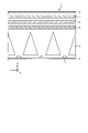
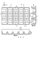
- FIG. 1 is a diagram for explaining light distribution characteristics required for a planar illumination device 1 according to an embodiment.
- FIG. 1 is an outline view of a planar lighting device 1 according to the embodiment. is the Z direction.
- the planar lighting device 1 has a substantially rectangular plate-like outer shape, and light is emitted from the inside of the opening 9 a of the frame 9 . It should be noted that the outer shape of the planar illumination device 1 is not limited to that illustrated. "Optical axis shift" shown in the figure means tilting the optical axis.
- the optical axis is tilted to the negative direction side of the Y axis of the planar lighting device 1 (diagonally to the lower right in the figure), indicating that a narrow visual field range is required.
- the light distribution characteristic in the X-axis direction of the planar lighting device 1 indicates that a wide visual field range is required with the normal direction of the light emitting surface as the optical axis.
- the planar illumination device 1 includes a first optical element that collects the light emitted from the light source, and a second optical element that tilts the light distribution of the light collected by the first optical element with respect to the Y-axis direction. and an optical element of The Y-axis direction is an example of a first axial direction. Note that the embodiment can be applied even when the first axial direction is the X-axis direction. A configuration example of the planar illumination device 1 of the embodiment will be described in detail below.
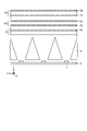
- FIG. 2 is a diagram for explaining the outline of the planar illumination device shown in FIG.
- FIG. 2 is a simplified view of the AA cross-sectional view of the planar lighting device 1 shown in FIG. Frame 9 is omitted in FIG.
- the AA cross-sectional view may be referred to as a vertical cross-sectional view.
- the BB cross-sectional view of the planar illumination device 1 shown in FIG. 1 may be referred to as a cross-sectional view.
- a plurality of light sources 3 such as LEDs (Light Emitting Diodes) are arranged on the substrate 2 .
- FIG. 2 shows a plurality of light sources 3 arranged in the Y-axis direction, a plurality of light sources 3 are also arranged in the X-axis direction (see FIG. 4 described later). That is, a plurality of light sources 3 are two-dimensionally arranged on the substrate 2 . Each of the plurality of light sources 3 is driven individually and can cope with so-called local dimming.
- a condenser lens 5 provided with a first optical element for condensing the light emitted from the plurality of light sources 3 is arranged on the emission side of the plurality of light sources 3 , and the light emitted from the plurality of light sources 3 is condensed by the condenser lens 5 .
- a light distribution lens 6 provided with a second optical element for tilting the distribution of light with respect to the Y-axis direction is arranged.
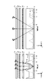
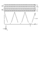
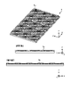
- FIG. 3 is a perspective view schematically showing the planar illumination device 1 shown in FIG. 1, and FIG. 4 is a sectional view taken along line AA and BB of the planar illumination device shown in FIG.
- the left figure in FIG. 4 is a vertical sectional view taken along line AA, and the right figure in FIG. 4 is a horizontal sectional view taken along line BB.
- the longitudinal sectional view of FIG. 4 schematically shows the behavior of light rays with respect to the Y-axis direction
- the transverse view of FIG. 4 schematically shows the behavior of light rays with respect to the X-axis direction.
- the condenser lens 5 extends in the X-axis direction orthogonal to the Y-axis direction, and has a linear Fresnel lens 5a as a first optical element that collects the light emitted from the plurality of light sources 3 in the Y-axis direction. have.
- the linear Fresnel lens 5a is provided on the surface opposite to the surface facing the substrate 2 (surface on the output side of the condenser lens 5). Note that the X-axis direction is an example of the second axial direction.
- the linear Fresnel lens 5a has a prism structure in which a cylindrical convex lens is a Fresnel lens, and has grooves extending in the X-axis direction.
- grooves are periodically formed in accordance with the pitch of the light sources 3 (pitch in the Y-axis direction) arranged directly below.
- the light distributing lens 6 has a linear prism 6a extending in the X-axis direction as a second optical element that tilts the light distribution of the light condensed by the condensing lens 5 with respect to the Y-axis direction.
- the linear prism 6a is provided on the surface opposite to the surface facing the condenser lens 5 (the exit-side surface of the light distribution lens 6).
- the linear prisms 6a have a substantially triangular prism structure extending in the X-axis direction and are arranged continuously in the Y-axis direction. As a result, grooves extending in the X-axis direction are formed on the exit-side surface of the light distributing lens 6 .
- the cross-sectional shape of the YZ plane of the linear prism 6a is a triangle, and the base angle of the side connecting the point on the positive Y-axis side of the base and the vertex is the point on the negative Y-axis side of the base and the vertex. smaller than the base angle of the side connecting
- the light emitted from the light source 3 enters the condenser lens 5 and is substantially refracted by the linear Fresnel lens 5a provided on the upper surface of the condenser lens 5.
- the light emitted from the condenser lens 5 enters the light distribution lens 6 and is substantially refracted by the linear prism 6a provided on the upper surface of the light distribution lens 6. output without
- the condenser lens 5 collects the light emitted from the plurality of light sources 3 and makes it enter the light distribution lens 6 as substantially parallel light efficiently. emits incident light with its optical axis tilted.
- the planar illumination device 1 can achieve the required light distribution characteristics with high luminance.
- the optical axis shift is not required in the X-axis direction, and the required field of view range is relatively wide. no need to focus.
- the condenser lens 5 of the embodiment is not provided with a linear Fresnel lens extending in the Y-axis direction, and the light distributing lens 6 is not provided with a linear prism extending in the Y-axis direction. .
- the effects of such a configuration will be detailed later.
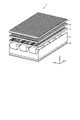
- the planar illumination device 1 has a viewing range adjusting lens as shown in FIGS. 7 is arranged on the output side of the light distributing lens 6 .
- the field-of-view range adjusting lens 7 has a first lenticular lens 7a provided on the surface facing the light distributing lens 6 (surface on the incident side) and the surface facing the light distributing lens 6. and a second lenticular lens 7b provided on the side surface (the surface on the leaving side).
- the first lenticular lens 7a extends in the X-axis direction and adjusts the viewing range in the Y-axis direction.
- the first lenticular lens 7a has a semicylindrical fine semicylindrical prism structure extending in the X-axis direction.
- the second lenticular lens 7b extends in the Y-axis direction and adjusts the luminance distribution in the X-axis direction.
- the second lenticular lens 7b has a semicylindrical fine semicylindrical prism structure extending in the Y-axis direction.
- a linear Fresnel lens that collects light, a linear prism that tilts toward the target optical axis, and a lenticular lens that both collects and diffuses light to adjust the viewing range and luminance distribution are combined. This makes it possible to control the light distribution to the target visual field range while ensuring high brightness and uniformity.
- the planar illumination device 1 may have a diffusion sheet 8 arranged on the output side of the viewing range adjusting lens 7 as shown in FIG.
- the diffusion sheet 8 is useful for eliminating streaky unevenness caused by the first lenticular lens 7a and the second lenticular lens 7b.
- a plurality of light sources 3 are emitted between the plurality of light sources 3 and the condenser lens 5.
- a reflector 4 is arranged in order to allow the light to enter the condensing lens 5 efficiently.
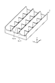
- the reflector 4 is formed so that openings 4b corresponding to the plurality of light sources 3 are arranged, and has a wall portion 4c that surrounds the openings 4b and serves as a reflecting surface 4a.
- reflector 4 has four reflective surfaces 4a surrounding opening 4b.
- the planar illumination device 1 of the embodiment is required to have a field of view characteristic of a wide field of view in the X-axis direction and a narrow field of view in the Y-axis direction.
- visual field characteristics are realized mainly by controlling the optical characteristics by the lens functions of the condenser lens 5, the light distributing lens 6, the visual field range adjusting lens 7, and the like.
- the structure of the reflector 4 located between the light source 3 and the lens may change the viewing characteristics obtained through the lens. Therefore, matching the structure of the reflector 4 with the required characteristics is preferable for ensuring the control of the light distribution to the target visual field range realized by the lens function described above.
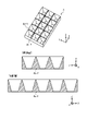
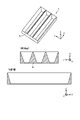
- FIG. 5 is a perspective view of the reflector shown in FIG. 3
- FIG. 6 is a front view, CC sectional view (vertical section) and DD sectional view (lateral section) of the reflector shown in FIG.
- the wall portion 4c has a shape in which a plurality of first wall portions 4c-1 extending in the Y-axis direction and a plurality of second wall portions 4c-2 extending in the X-axis direction are assembled in a lattice. ing.
- the wall portion 4c is assembled so that the bottom surface of the first wall portion 4c-1 and the bottom surface of the second wall portion 4c-2 are flush with each other.
- the reflecting surface 4a is the wall surface of the wall portion 4c.
- the two reflecting surfaces 4a-1 facing each other between the two first walls 4c-1 adjacent in the X-axis direction are inclined away from each other toward the positive Z-axis direction.
- the reflector 4 is made of, for example, white resin or the like in order to enhance the effect of reflection.
- the reflector 4 of the embodiment is an injection-molded product.
- the height of the first wall portion 4c-1 is defined by the viewing range in the X-axis direction
- the height of the second wall portion 4c-2 is defined by the viewing range in the Y-axis direction.
- the height of the second wall portion 4c-2 is increased as shown in the longitudinal section of FIG.
- increasing the height of the second wall portion 4c-2 also plays a role of blocking light entering the linear Fresnel lens 5a of the adjacent segment, and also has a function of avoiding unintended light distribution. .
- the height of the second wall portion 4c-2 extending in the X-axis direction (longitudinal direction) is higher than the height of the first wall portion 4c-1 extending in the Y-axis direction (lateral direction).
- the reflector 4 of the embodiment is arranged so that the opening 4b is located on the emission side of the light emitting surface of the light source 3, as shown in FIG.
- a light emitting surface of the light source 3 corresponds to the top surface of the light source 3 .
- the bottom surface 4d of the wall portion 4c of the reflector 4 is positioned above the light emitting surface of the light source 3, floating above the substrate 2. As shown in FIG.
- the visual field range adjusting lens 7 is provided with lenticular lenses in both the X-axis direction and the Y-axis direction. However, since the lenticular lenses have the same shape and pattern, there is no need to consider lens displacement.
- the wall portion 4c of the reflector 4 and the light source 3 are in close proximity, and when the reflector 4 and the light source 3 expand and contract, they may interfere with each other.
- the opening 4b of the reflector 4 is arranged at a position higher than the light emitting surface of the light source 3, even if the reflector 4 and the light source 3 expand and contract, the wall portion 4c of the reflector 4 and There is no possibility of contact with the light source 3.
- the opening 4b of the reflector 4 can be made smaller than the outer periphery of the light source 3 as long as it is larger than the light emitting surface of the light source 3 in top view. That is, in the embodiment, the opening 4b can be made smaller.
- the bottom surface 4d can be enlarged, and as a result, the walls 4c of the reflector 4, which are made by injection molding, can be raised. For this reason, in the embodiment, effects such as high contrast during local dimming and elimination of unnecessary light distribution can be obtained.
- planar illumination device 1 described in the above embodiment is merely an example, and various modifications are possible. Modifications of the planar illumination device 1 will be described below.
- the planar illumination device 1 of the first modification has the same prism structure (linear Fresnel lens 5a, linear prism 6a, first lenticular lens 7a, second lenticular lens 7b) as in the embodiment, but each prism
- the arrangement of structures differs from the embodiment.
- FIG. 7 is a diagram for explaining the first modified example.
- the planar illumination device 1 of the first modified example includes, as the first lens, a condensing lens 5 provided with a linear Fresnel lens 5a on the surface opposite to the surface facing the substrate 2, as in the embodiment. is provided as the first lens.
- the planar illumination device 1 of the first modified example includes a second lens 60 and a third lens 70 .
- the second lens 60 has a second lenticular lens 7b provided on the surface facing the first lens (condensing lens 5), and the surface opposite to the surface facing the first lens (condensing lens 5).
- a linear prism 6a extending in the X-axis direction is provided.
- the third lens 70 is provided with the first lenticular lens 7 a on the surface facing the second lens 60 .
- the light emitted from the light source 3 is condensed by the emission surface of the light distribution lens 5 (first lens) to become substantially parallel light, and the emission surface of the second lens 60
- the optical axis is tilted at , and the viewing range is adjusted at the incident surface of the third lens 70 .
- the luminance distribution of the light emitted from the light source 3 is adjusted by the incident surface of the second lens 60 in the X-axis direction. Even with such a configuration order of the lenses, it is possible to achieve the required light distribution characteristics while ensuring high brightness, as in the embodiment.
- a diffusion surface 80 is formed on the surface of the third lens 70 opposite to the surface facing the second lens 60 .
- the diffusion surface 80 having the same function as the diffusion sheet 8 is formed on the upper surface of the third lens 70. can reduce the number of parts.
- the planar illumination device 1 of the second modification has the same prism structure (linear Fresnel lens 5a, linear prism 6a, first lenticular lens 7a, second lenticular lens 7b) as in the embodiment, but each prism
- the arrangement of structures and the number of lenses are different from the embodiment.
- FIG. 8 is a diagram for explaining the second modification.
- the planar lighting device 1 of the second modified example includes a first lens 51 and a second lens 61 .
- the first lens 51 has a linear Fresnel lens 5 a provided on the surface facing the substrate 2 and a linear prism 6 a provided on the surface opposite to the surface facing the substrate 2 .
- the second lens 61 is arranged on the output side of the first lens 51, and the second lenticular lens 7b is provided on the surface facing the first lens.
- a first lenticular lens 7a is provided on the surface.
- the light emitted from the light source 3 is condensed on the incident surface of the first lens 51 to become substantially parallel light, and the optical axis is tilted on the output surface of the first lens 51.
- the field of view range is adjusted by the output surface of the second lens 61 .
- the luminance distribution of the light emitted from the light source 3 is adjusted by the incident surface of the second lens 61 in the X-axis direction. Even with such a configuration order of the lenses, it is possible to achieve the required light distribution characteristics while ensuring high brightness, as in the embodiment.
- the planar illumination device 1 of the third modification includes two lenses, and prisms (linear Fresnel lens 5a, first lenticular lens 7a, second Although it has a lenticular lens 7b), the shape of the linear prism for optical axis shift is different from that of the linear prism 6a.
- FIG. 9 is a diagram for explaining the third modification.
- a planar illumination device 1 of the third modification includes a first lens 52 and a second lens 62 .
- the first lens 52 has a linear Fresnel lens 5 a provided on the surface facing the substrate 2 and a second lenticular lens 7 b provided on the surface opposite to the surface facing the substrate 2 .
- the second lens 62 has a linear prism 62a extending in the X-axis direction as a second optical element.
- a first lenticular lens 7a is provided on the surface opposite to the surface facing the lens.
- the linear prisms 62a have a substantially triangular prism structure extending in the X-axis direction and are arranged continuously in the Y-axis direction.
- the cross-sectional shape of the YZ plane of the linear prism 62a is an inverted triangle. greater than the base angle of the side connecting the vertex.
- the light emitted from the light source 3 is condensed by the incident surface of the first lens 52 and becomes substantially parallel light, and the optical axis is tilted by the incident surface of the second lens 62. , and the viewing range is adjusted by the output surface of the second lens 62 .
- the luminance distribution of the light emitted from the light source 3 is adjusted by the emission surface of the first lens 52 in the X-axis direction. Even with such a configuration order of the lenses, it is possible to achieve the required light distribution characteristics while ensuring high brightness, as in the embodiment.
- the lens configuration is not limited to Modifications 1 to 3 above.
- the first lens 52 may have any configuration, such as providing the second lenticular lens 7b on the entrance surface and providing the linear Fresnel lens 5a on the exit surface.
- the bottom surface of the reflector 4 is arranged at a position higher than the light emitting surface of the light source 3. If possible, the bottom surface of the reflector 4 may be grounded to the substrate 2 .
- FIG. 10 is a diagram for explaining a fourth modification.
- the height of the first wall portion 4c-1 is adjusted to match the viewing range in the X-axis direction
- the height of the second wall portion 4c-2 is adjusted to match the viewing range in the Y-axis direction. I was adjusting accordingly.
- the height of the first wall portion 4c-1 and the height of the second wall portion 4c-2 height is the same height.
- FIG. 11 is a diagram for explaining a fifth modification.
- the fifth modification has a reflector structure in which no reflective surface extending in the Y-axis direction is provided between adjacent light sources 3 in the X-axis direction, which is the direction in which the field of view is widened. .
- the wall portions 4c extend in the X-axis direction and are arranged along the Y-axis direction in accordance with the intervals at which the plurality of light sources 3 are arranged in the Y-axis direction.
- the height of the wall portion 4c is defined by the visual field range in the Y-axis direction.
- FIG. 12 is a diagram for explaining a sixth modification.
- light is collected only in the Y-axis direction of the substrate 2, but light may also be collected in the X-axis direction of the substrate 2 as long as the required light distribution characteristics can be achieved.
- a linear Fresnel lens 5a which is a first linear Fresnel lens extending in the X-axis direction and condensing light in the Y-axis direction, is used as the first optical element.
- a second linear Fresnel lens 5b extending in the Y-axis direction and condensing light in the X-axis direction.
- the second linear Fresnel lens 5b has a prism structure using a cylindrical convex lens as a Fresnel lens, and has grooves extending in the Y-axis direction.
- the condenser lens 5 of the sixth modification shown in FIG. 12 has the second linear Fresnel lens 5b on the incident side and the first linear Fresnel lens 5a on the outgoing side. good.
- the seventh modified example a modified example of the condensing lens 5 that has a prism structure different from that in the sixth modified example and collects light in both the Y-axis direction and the X-axis direction will be described.
- a concentric fresnel lens 5c that collects light in the Y-axis direction and the X-axis direction is provided as the first optical element.
- the concentric Fresnel lens 5c is a lens obtained by dividing a convex lens into concentric regions to reduce the thickness, and has a serrated cross section.
- the concentric Fresnel lenses 5c are provided for the number of light sources 3 corresponding to the light sources 3 arranged directly below.
- the condensing lens 5 of the seventh modification shown in FIG. 13 has a concentric Fresnel lens 5c on the output side, but it may be provided on the incident side.
- light distribution control is performed by prisms such as the linear Fresnel lens 5a, the first lenticular lens 7a, the second lenticular lens 7b, and the reflector.
- prisms such as the linear Fresnel lens 5a, the first lenticular lens 7a, the second lenticular lens 7b, and the reflector.
- the present invention is not limited by the above embodiments.
- the present invention also includes those configured by appropriately combining the respective constituent elements described above. Further effects and modifications can be easily derived by those skilled in the art. Therefore, broader aspects of the present invention are not limited to the above-described embodiments, and various modifications are possible.
- 1 planar lighting device 2 substrate, 3 light source, 4 reflector, 4a, 4a-1, 4b-1 reflective surface, 4b aperture, 4c wall, 4c-1 first wall, 4c-2 second wall Part, 5 condenser lens, 5a linear Fresnel lens (first linear Fresnel lens), 6 light distributing lens, 6a linear prism, 7 field range adjusting lens, 7a first lenticular lens, 7b second lenticular lens, 8 Diffusion sheet, 9 frames
Abstract
A planar illumination device (1) according to an embodiment of the present invention is provided with: a substrate (2); a first optical element (5a); and a second optical element (6a). A plurality of light sources (3) are two-dimensionally disposed on the substrate (2). The first optical element (5a) is disposed on the emission side of the plurality of light sources (3), and collects light emitted from the plurality of light sources (3). The second optical element (6a) tilts, with respect to a first axial direction (Y-axis direction), the distribution of light collected by the first optical element (5a).
Description
本発明は、面状照明装置に関する。
The present invention relates to a planar lighting device.
液晶表示装置のバックライトとして用いられる面状照明装置では、用途に応じた配光特性を実現するため様々な光学レンズが用いられる(例えば、特許文献1、2を参照)。
In planar lighting devices used as backlights for liquid crystal display devices, various optical lenses are used to achieve light distribution characteristics according to the application (see Patent Documents 1 and 2, for example).
液晶表示装置のバックライトの特性として、高輝度化、高効率化とともに、光軸を傾けるなどの特殊な配光特性が要求されてきている。しかしながら、従来の装置では、高輝度化を確保しつつ、要求される視野範囲に対して効率良く光の配光を制御することが困難であった。
As the characteristics of the backlight of liquid crystal display devices, special light distribution characteristics such as tilting the optical axis are required in addition to high brightness and high efficiency. However, with the conventional device, it is difficult to efficiently control the light distribution for the required visual field range while ensuring high brightness.
本発明は、上記に鑑みてなされたものであって、高輝度化を確保しつつ、要求される配光特性を実現することができる面状照明装置を提供することを目的とする。
The present invention has been made in view of the above, and it is an object of the present invention to provide a planar lighting device capable of realizing required light distribution characteristics while ensuring high brightness.
上述した課題を解決し、目的を達成するために、本発明の一態様に係る面状照明装置は、基板と、第1の光学素子と、第2の光学素子とを備える。前記基板は、複数の光源が2次元に配置される。前記第1の光学素子は、前記複数の光源の出射側に配置され、前記複数の光源から出射された光を集光する。前記第2の光学素子は、前記第1の光学素子によって集光された光の配光を第1の軸方向に対して傾ける。
In order to solve the above-described problems and achieve the object, a planar illumination device according to one aspect of the present invention includes a substrate, a first optical element, and a second optical element. A plurality of light sources are two-dimensionally arranged on the substrate. The first optical element is arranged on the emission side of the plurality of light sources and condenses the light emitted from the plurality of light sources. The second optical element tilts the light distribution of the light condensed by the first optical element with respect to the first axial direction.
本発明の一態様に係る面状照明装置は、高輝度化を確保しつつ、要求される配光特性を実現することができる。
A planar lighting device according to an aspect of the present invention can realize required light distribution characteristics while ensuring high luminance.
以下、実施形態に係る面状照明装置について図面を参照して説明する。なお、この実施形態によりこの発明が限定されるものではない。また、図面における各要素の寸法の関係、各要素の比率などは、現実と異なる場合がある。図面の相互間においても、互いの寸法の関係や比率が異なる部分が含まれている場合がある。また、1つの実施形態や変形例に記載された内容は、原則として他の実施形態や変形例にも同様に適用される。
A planar illumination device according to an embodiment will be described below with reference to the drawings. In addition, this invention is not limited by this embodiment. In addition, the dimensional relationship of each element in the drawings, the ratio of each element, and the like may differ from reality. Even between the drawings, there are cases where portions with different dimensional relationships and ratios are included. In principle, the contents described in one embodiment and modification are similarly applied to other embodiments and modifications.
(実施形態)
図1は、実施形態にかかる面状照明装置1に要求される配光特性を説明するための図である。図1は、実施形態にかかる面状照明装置1の外形図であり、図1では、便宜上、面状照明装置1の発光面がX-Y平面内にあり、面状照明装置1の厚み方向をZ方向としている。 (embodiment)
FIG. 1 is a diagram for explaining light distribution characteristics required for aplanar illumination device 1 according to an embodiment. FIG. 1 is an outline view of a planar lighting device 1 according to the embodiment. is the Z direction.
図1は、実施形態にかかる面状照明装置1に要求される配光特性を説明するための図である。図1は、実施形態にかかる面状照明装置1の外形図であり、図1では、便宜上、面状照明装置1の発光面がX-Y平面内にあり、面状照明装置1の厚み方向をZ方向としている。 (embodiment)
FIG. 1 is a diagram for explaining light distribution characteristics required for a
図1において、面状照明装置1は、略長方形状の板状の外形を有しており、フレーム9の開口9aの内側から光が出射するようになっている。なお、面状照明装置1の外形は図示のものに限られない。図に示す「光軸シフト」は、光軸を傾けることを意味する。
In FIG. 1 , the planar lighting device 1 has a substantially rectangular plate-like outer shape, and light is emitted from the inside of the opening 9 a of the frame 9 . It should be noted that the outer shape of the planar illumination device 1 is not limited to that illustrated. "Optical axis shift" shown in the figure means tilting the optical axis.
図1に示す一例では、面状照明装置1のY軸の負方向側(図では斜め右下)に光軸を傾け、狭い視野範囲が要求されていることを示している。一方、図1に示す一例では、面状照明装置1のX軸方向における配光特性として、発光面の法線方向を光軸として広い視野範囲が要求されていることを示している。
In the example shown in FIG. 1, the optical axis is tilted to the negative direction side of the Y axis of the planar lighting device 1 (diagonally to the lower right in the figure), indicating that a narrow visual field range is required. On the other hand, in the example shown in FIG. 1, the light distribution characteristic in the X-axis direction of the planar lighting device 1 indicates that a wide visual field range is required with the normal direction of the light emitting surface as the optical axis.
そこで、面状照明装置1は、光源から出射された光を集光する第1の光学素子と、第1の光学素子によって集光された光の配光をY軸方向に対して傾ける第2の光学素子とを備える。Y軸方向は、第1の軸方向の一例である。なお、実施形態は、第1の軸方向をX軸方向とする場合でも適用可能である。以下、実施形態の面状照明装置1の構成例について詳細に説明する。
Therefore, the planar illumination device 1 includes a first optical element that collects the light emitted from the light source, and a second optical element that tilts the light distribution of the light collected by the first optical element with respect to the Y-axis direction. and an optical element of The Y-axis direction is an example of a first axial direction. Note that the embodiment can be applied even when the first axial direction is the X-axis direction. A configuration example of the planar illumination device 1 of the embodiment will be described in detail below.
図2は、図1に示す面状照明装置の概要を説明するための図である。図2は、図1に示す面状照明装置1のA-A断面図を簡略化した図である。図2では、フレーム9は省略している。なお、以下では、A-A断面図を縦断図と記載する場合がある。また、図1に示す面状照明装置1のB-B断面図を横断図と記載する場合がある。
FIG. 2 is a diagram for explaining the outline of the planar illumination device shown in FIG. FIG. 2 is a simplified view of the AA cross-sectional view of the planar lighting device 1 shown in FIG. Frame 9 is omitted in FIG. In the following description, the AA cross-sectional view may be referred to as a vertical cross-sectional view. Further, the BB cross-sectional view of the planar illumination device 1 shown in FIG. 1 may be referred to as a cross-sectional view.
図2において、基板2の上には、LED(Light Emitting Diode)等による複数の光源3が配置されている。なお、図2ではY軸方向に配置された複数の光源3が図示されているが、X軸方向おいても、複数の光源3が複数配置されている(後述する図4参照)。すなわち、基板2には、複数の光源3が2次元に配置されている。複数の光源3それぞれは、個別に駆動が行われ、いわゆるローカルディミングに対応することができる。
In FIG. 2, a plurality of light sources 3 such as LEDs (Light Emitting Diodes) are arranged on the substrate 2 . Although FIG. 2 shows a plurality of light sources 3 arranged in the Y-axis direction, a plurality of light sources 3 are also arranged in the X-axis direction (see FIG. 4 described later). That is, a plurality of light sources 3 are two-dimensionally arranged on the substrate 2 . Each of the plurality of light sources 3 is driven individually and can cope with so-called local dimming.
そして、複数の光源3の出射側には、複数の光源3から出射された光を集光する第1の光学素子が設けられた集光レンズ5が配置され、集光レンズ5によって集光された光の配光をY軸方向に対して傾ける第2の光学素子が設けられた配光レンズ6が配置される。集光レンズ5及び配光レンズ6について、図3及び図4を用いて説明する。
A condenser lens 5 provided with a first optical element for condensing the light emitted from the plurality of light sources 3 is arranged on the emission side of the plurality of light sources 3 , and the light emitted from the plurality of light sources 3 is condensed by the condenser lens 5 . A light distribution lens 6 provided with a second optical element for tilting the distribution of light with respect to the Y-axis direction is arranged. The condenser lens 5 and the light distribution lens 6 will be described with reference to FIGS. 3 and 4. FIG.
図3は、図1に示す面状照明装置1を模式的に示す斜視図であり、図4は、図1に示す面状照明装置のA-A断面図及びB-B断面図である。図4の左図は、縦断面図であるA-A断面図であり、図4の右図は、横断面図であるB-B断面図である。なお、図4の縦断図には、Y軸方向に対する光線のふるまいを模式的に示し、図4の横断図には、X軸方向に対する光線のふるまいを模式的に示している。
3 is a perspective view schematically showing the planar illumination device 1 shown in FIG. 1, and FIG. 4 is a sectional view taken along line AA and BB of the planar illumination device shown in FIG. The left figure in FIG. 4 is a vertical sectional view taken along line AA, and the right figure in FIG. 4 is a horizontal sectional view taken along line BB. The longitudinal sectional view of FIG. 4 schematically shows the behavior of light rays with respect to the Y-axis direction, and the transverse view of FIG. 4 schematically shows the behavior of light rays with respect to the X-axis direction.
集光レンズ5は、Y軸方向と直交するX軸方向に延在し、複数の光源3から出射された光をY軸方向に対して集光するリニアフレネルレンズ5aを第1の光学素子として有する。リニアフレネルレンズ5aは、基板2に対向する面とは反対側の面(集光レンズ5の出射側の面)に設けられる。なお、X軸方向は、第2の軸方向の一例である。
The condenser lens 5 extends in the X-axis direction orthogonal to the Y-axis direction, and has a linear Fresnel lens 5a as a first optical element that collects the light emitted from the plurality of light sources 3 in the Y-axis direction. have. The linear Fresnel lens 5a is provided on the surface opposite to the surface facing the substrate 2 (surface on the output side of the condenser lens 5). Note that the X-axis direction is an example of the second axial direction.
リニアフレネルレンズ5aは、シリンダ状の凸レンズをフレネルレンズとしたプリズム構造を有しており、X軸方向に延びる溝を有している。リニアフレネルレンズ5aは、直下に配置される光源3のピッチ(Y軸方向のピッチ)に合わせて溝が周期的に形成されている。
The linear Fresnel lens 5a has a prism structure in which a cylindrical convex lens is a Fresnel lens, and has grooves extending in the X-axis direction. In the linear Fresnel lens 5a, grooves are periodically formed in accordance with the pitch of the light sources 3 (pitch in the Y-axis direction) arranged directly below.
配光レンズ6は、集光レンズ5によって集光された光の配光をY軸方向に対して傾ける第2の光学素子として、X軸方向に延在するリニアプリズム6aを有する。リニアプリズム6aは、集光レンズ5に対向する面とは反対側の面(配光レンズ6の出射側の面)に設けられる。リニアプリズム6aは、X軸方向に延在する略三角柱のプリズム構造を有し、Y軸方向に連続して配置される。これにより、配光レンズ6の出射側の面には、X軸方向に延びる溝が形成される。リニアプリズム6aのY-Z面の断面形状は、三角形であり、底辺のY軸の正方向側の点と頂点とを結ぶ辺の底角は、底辺のY軸の負方向側の点と頂点とを結ぶ辺の底角より小さい。
The light distributing lens 6 has a linear prism 6a extending in the X-axis direction as a second optical element that tilts the light distribution of the light condensed by the condensing lens 5 with respect to the Y-axis direction. The linear prism 6a is provided on the surface opposite to the surface facing the condenser lens 5 (the exit-side surface of the light distribution lens 6). The linear prisms 6a have a substantially triangular prism structure extending in the X-axis direction and are arranged continuously in the Y-axis direction. As a result, grooves extending in the X-axis direction are formed on the exit-side surface of the light distributing lens 6 . The cross-sectional shape of the YZ plane of the linear prism 6a is a triangle, and the base angle of the side connecting the point on the positive Y-axis side of the base and the vertex is the point on the negative Y-axis side of the base and the vertex. smaller than the base angle of the side connecting
図4の縦断図おいて、光源3から出射された光は、集光レンズ5に入射し、集光レンズ5の上側の面に設けられたリニアフレネルレンズ5aによって屈折し、略平行光となって出射する。そして、図4の縦断図おいて、集光レンズ5から出射された平行光は、配光レンズ6に入射し、配光レンズ6の上側の面に設けられたリニアプリズム6aによって光軸が傾けられて出射する。
In the longitudinal sectional view of FIG. 4, light emitted from the light source 3 enters a condenser lens 5, is refracted by a linear Fresnel lens 5a provided on the upper surface of the condenser lens 5, and becomes substantially parallel light. to emit. 4, the parallel light emitted from the condenser lens 5 is incident on the light distribution lens 6, and the optical axis is tilted by the linear prism 6a provided on the upper surface of the light distribution lens 6. is ejected.
一方、図4の横断図おいて、光源3から出射された光は、集光レンズ5に入射して、集光レンズ5の上側の面に設けられたリニアフレネルレンズ5aによって略屈折されずに出射する。そして、図4の横断図おいて、集光レンズ5から出射された光は、配光レンズ6に入射して、配光レンズ6の上側の面に設けられたリニアプリズム6aによっては略屈折されずに出射する。
On the other hand, in the cross-sectional view of FIG. 4, the light emitted from the light source 3 enters the condenser lens 5 and is substantially refracted by the linear Fresnel lens 5a provided on the upper surface of the condenser lens 5. emit. 4, the light emitted from the condenser lens 5 enters the light distribution lens 6 and is substantially refracted by the linear prism 6a provided on the upper surface of the light distribution lens 6. output without
このように、Y軸方向に対しては、集光レンズ5は、複数の光源3から出射された光を集光して略平行光として配光レンズ6に効率よく入射させ、配光レンズ6は、入射光の光軸を傾けて出射させる。これにより、面状照明装置1は、要求される配光特性を高輝度で実現することができる。なお、実施形態は、X軸方向に対しては、光軸シフトは必要ではなく、また、要求される視野範囲が比較的広いので、複数の光源3から出射された光をX軸方向に対して集光する必要がない。このことから、実施形態の集光レンズ5には、Y軸方向に延在するリニアフレネルレンズを設けておらず、配光レンズ6には、Y軸方向に延在するリニアプリズムを設けていない。かかる構成による効果については後に詳述する。
In this way, in the Y-axis direction, the condenser lens 5 collects the light emitted from the plurality of light sources 3 and makes it enter the light distribution lens 6 as substantially parallel light efficiently. emits incident light with its optical axis tilted. As a result, the planar illumination device 1 can achieve the required light distribution characteristics with high luminance. In this embodiment, the optical axis shift is not required in the X-axis direction, and the required field of view range is relatively wide. no need to focus. For this reason, the condenser lens 5 of the embodiment is not provided with a linear Fresnel lens extending in the Y-axis direction, and the light distributing lens 6 is not provided with a linear prism extending in the Y-axis direction. . The effects of such a configuration will be detailed later.
更に、実施形態にかかる面状照明装置1は、配光レンズ6から出射した光を、要求されている視野範囲とするため、図2、図3及び図4に示すように、視野範囲調整レンズ7を配光レンズ6の出射側に配置する。視野範囲調整レンズ7は、図4に示すように、配光レンズ6に対向する面(入射側の面)に設けられる第1のレンチキュラーレンズ7aと、配光レンズ6に対向する面とは反対側の面(出社側の面)に設けられる第2のレンチキュラーレンズ7bとを有する。
Furthermore, the planar illumination device 1 according to the embodiment has a viewing range adjusting lens as shown in FIGS. 7 is arranged on the output side of the light distributing lens 6 . As shown in FIG. 4, the field-of-view range adjusting lens 7 has a first lenticular lens 7a provided on the surface facing the light distributing lens 6 (surface on the incident side) and the surface facing the light distributing lens 6. and a second lenticular lens 7b provided on the side surface (the surface on the leaving side).
第1のレンチキュラーレンズ7aは、X軸方向に延在し、Y軸方向における視野範囲を調整する。第1のレンチキュラーレンズ7aは、X軸方向に延在するかまぼこ状の微細半円筒型のプリズム構造を有している。また、第2のレンチキュラーレンズ7bは、Y軸方向に延在し、X軸方向における輝度分布を調整する。第2のレンチキュラーレンズ7bは、Y軸方向に延在するかまぼこ状の微細半円筒型のプリズム構造を有している。
The first lenticular lens 7a extends in the X-axis direction and adjusts the viewing range in the Y-axis direction. The first lenticular lens 7a has a semicylindrical fine semicylindrical prism structure extending in the X-axis direction. The second lenticular lens 7b extends in the Y-axis direction and adjusts the luminance distribution in the X-axis direction. The second lenticular lens 7b has a semicylindrical fine semicylindrical prism structure extending in the Y-axis direction.
このように、実施形態では、集光を行うリニアフレネルレンズと、目標の光軸へ傾けるリニアプリズムと、集光と拡散との双方を行って視野範囲及び輝度分布を調整するレンチキュラーレンズとを組み合わせることで、高輝度化と均一性を確保しつつ、目標の視野範囲への配光制御を可能とすることができる。
Thus, in the embodiment, a linear Fresnel lens that collects light, a linear prism that tilts toward the target optical axis, and a lenticular lens that both collects and diffuses light to adjust the viewing range and luminance distribution are combined. This makes it possible to control the light distribution to the target visual field range while ensuring high brightness and uniformity.
なお、図3及び図4には図示していないが、面状照明装置1は、図2に示すように、視野範囲調整レンズ7の出射側に拡散シート8が配置されても良い。拡散シート8は、第1のレンチキュラーレンズ7aや第2のレンチキュラーレンズ7bに起因する筋状のムラ等を解消するために有用である。
Although not shown in FIGS. 3 and 4, the planar illumination device 1 may have a diffusion sheet 8 arranged on the output side of the viewing range adjusting lens 7 as shown in FIG. The diffusion sheet 8 is useful for eliminating streaky unevenness caused by the first lenticular lens 7a and the second lenticular lens 7b.
そして、直下型バックライトである面状照明装置1では、図2、図3及び図4に示すように、複数の光源3と、集光レンズ5との間には、複数の光源3が出射する光を効率良く集光レンズ5に入射させるため、リフレクタ4が配置されている。リフレクタ4は、図4に示すように、複数の光源3それぞれに対応する開口4bが配列されるように形成され、開口4bを囲う壁面が反射面4aとなる壁部4cを有する。実施形態では、リフレクタ4は、開口4bを囲む4つの反射面4aを有する。
2, 3 and 4, in the planar illumination device 1 which is a direct type backlight, a plurality of light sources 3 are emitted between the plurality of light sources 3 and the condenser lens 5. A reflector 4 is arranged in order to allow the light to enter the condensing lens 5 efficiently. As shown in FIG. 4, the reflector 4 is formed so that openings 4b corresponding to the plurality of light sources 3 are arranged, and has a wall portion 4c that surrounds the openings 4b and serves as a reflecting surface 4a. In the embodiment, reflector 4 has four reflective surfaces 4a surrounding opening 4b.
実施形態の面状照明装置1は、X軸方向は広視野となり、Y軸方向は狭視野となる視野特性が求められる。上記の実施形態では、主に上述した集光レンズ5、配光レンズ6、視野範囲調整レンズ7等のレンズ機能による光学特性の制御により、かかる視野特性を実現している。しかし、光源3とレンズとの中間に位置するリフレクタ4の構造によって、レンズを介して得られる視野特性が変化する可能性がある。従って、リフレクタ4の構造を、要求される特性に合わせることが、上述したレンズ機能により実現できた目標の視野範囲への配光制御を確実にするうえで好適である。
The planar illumination device 1 of the embodiment is required to have a field of view characteristic of a wide field of view in the X-axis direction and a narrow field of view in the Y-axis direction. In the above-described embodiment, such visual field characteristics are realized mainly by controlling the optical characteristics by the lens functions of the condenser lens 5, the light distributing lens 6, the visual field range adjusting lens 7, and the like. However, the structure of the reflector 4 located between the light source 3 and the lens may change the viewing characteristics obtained through the lens. Therefore, matching the structure of the reflector 4 with the required characteristics is preferable for ensuring the control of the light distribution to the target visual field range realized by the lens function described above.
以下、実施形態にかかるリフレクタの構造について、図5及び図6を用いて説明する。図5は、図3に示すリフレクタの斜視図であり、図6は、図3に示すリフレクタの正面図、C-C断面図(縦断面)及びD-D断面図(横断面)である。
The structure of the reflector according to the embodiment will be described below with reference to FIGS. 5 and 6. FIG. 5 is a perspective view of the reflector shown in FIG. 3, and FIG. 6 is a front view, CC sectional view (vertical section) and DD sectional view (lateral section) of the reflector shown in FIG.
壁部4cは、Y軸方向に延在する複数の第1の壁部4c-1とX軸方向に延在する複数の第2の壁部4c-2とを格子状に組み立てた形状となっている。なお、壁部4cは、第1の壁部4c-1の底面と第2の壁部4c-2の底面が面一となるように組み立てられる。反射面4aは、壁部4cの壁面である。X軸方向で隣り合う2つの第1の壁部4c-1の間で対向する2つの反射面4a-1は、Z軸正方向に向かうにつれて互いに離れるように傾斜している。また、Y軸方向で隣り合う2つの第2の壁部4c-2の間で対向する2つの反射面4a-2は、Z軸正方向に向かうにつれて互いに離れるように傾斜している。リフレクタ4は、反射の効果を高めるため、例えば、白色の樹脂等により形成される。実施形態のリフレクタ4は、射出成型による成形品である。
The wall portion 4c has a shape in which a plurality of first wall portions 4c-1 extending in the Y-axis direction and a plurality of second wall portions 4c-2 extending in the X-axis direction are assembled in a lattice. ing. The wall portion 4c is assembled so that the bottom surface of the first wall portion 4c-1 and the bottom surface of the second wall portion 4c-2 are flush with each other. The reflecting surface 4a is the wall surface of the wall portion 4c. The two reflecting surfaces 4a-1 facing each other between the two first walls 4c-1 adjacent in the X-axis direction are inclined away from each other toward the positive Z-axis direction. Two reflecting surfaces 4a-2 facing each other between two second wall portions 4c-2 adjacent in the Y-axis direction are inclined away from each other toward the positive Z-axis direction. The reflector 4 is made of, for example, white resin or the like in order to enhance the effect of reflection. The reflector 4 of the embodiment is an injection-molded product.
そして、第1の壁部4c-1の高さは、X軸方向に対する視野範囲により規定され、第2の壁部4c-2の高さは、Y軸方向に対する視野範囲により規定される。実施形態では、Y軸方向においては、狭視野特性が求められるため、図6の縦断面に示すように、第2の壁部4c-2の高さを高くする。第2の壁部4c-2を高くすることで、光源3からの広い配光成分を反射面4a-2で反射させ、当該光源3に対応するセグメントのリニアフレネルレンズ5aに集めることができる。
The height of the first wall portion 4c-1 is defined by the viewing range in the X-axis direction, and the height of the second wall portion 4c-2 is defined by the viewing range in the Y-axis direction. In the embodiment, since a narrow field of view characteristic is required in the Y-axis direction, the height of the second wall portion 4c-2 is increased as shown in the longitudinal section of FIG. By increasing the height of the second wall portion 4c-2, a wide light distribution component from the light source 3 can be reflected by the reflecting surface 4a-2 and collected by the linear Fresnel lens 5a of the segment corresponding to the light source 3.
また、第2の壁部4c-2を高くすることは、隣接するセグメントのリニアフレネルレンズ5aへ入り込む光を遮断する役割も担っており、意図しない配光が発生することを回避する機能も有する。
Further, increasing the height of the second wall portion 4c-2 also plays a role of blocking light entering the linear Fresnel lens 5a of the adjacent segment, and also has a function of avoiding unintended light distribution. .
一方、実施形態では、X軸方向においては、広視野特性が求められるため、図6の横断面に示すように、第1の壁部4c-1の高さを低くすることで光源3からの広い配光成分を遮断せずに利用している。実施形態では、X軸方向(長手方向)に延びる第2の壁部4c-2の高さは、Y軸方向(短手方向)に延びる第1の壁部4c-1の高さより高い。
On the other hand, in the embodiment, since a wide field-of-view characteristic is required in the X-axis direction, as shown in the cross section of FIG. A wide light distribution component is used without blocking. In the embodiment, the height of the second wall portion 4c-2 extending in the X-axis direction (longitudinal direction) is higher than the height of the first wall portion 4c-1 extending in the Y-axis direction (lateral direction).
そして、実施形態のリフレクタ4は、図4に示すように、開口4bが光源3の発光面より出射側に位置するように配置されている。光源3の発光面は、光源3の上面に対応する。換言すると、リフレクタ4の壁部4cの底面4dは、図4に示すように、光源3の発光面より高い位置になるように、基板2から浮いた状態で配置される。
The reflector 4 of the embodiment is arranged so that the opening 4b is located on the emission side of the light emitting surface of the light source 3, as shown in FIG. A light emitting surface of the light source 3 corresponds to the top surface of the light source 3 . In other words, as shown in FIG. 4, the bottom surface 4d of the wall portion 4c of the reflector 4 is positioned above the light emitting surface of the light source 3, floating above the substrate 2. As shown in FIG.
実施形態では、基板2の短手方向(Y軸方向)に対する集光のみを行うため、基板2の長手方向(X軸方向)に延在する一軸のリニアフレネルレンズ5aのみを採用している。その結果、実施形態では、長辺方向のレンズ位置ずれを無視することができる。なお、実施形態では、視野範囲調整レンズ7において、X軸方向、Y軸方向の双方においてレンチキュラーレンズを設けているが、レンチキュラーレンズは同一形状パターンのため、レンズ位置ずれの考慮は不要である。
In the embodiment, only the uniaxial linear Fresnel lens 5a extending in the longitudinal direction (X-axis direction) of the substrate 2 is used in order to collect light only in the lateral direction (Y-axis direction) of the substrate 2. As a result, in the embodiment, lens misalignment in the long side direction can be ignored. In the embodiment, the visual field range adjusting lens 7 is provided with lenticular lenses in both the X-axis direction and the Y-axis direction. However, since the lenticular lenses have the same shape and pattern, there is no need to consider lens displacement.
リフレクタ4を基板2に接地させた場合、リフレクタ4の壁部4cと光源3とが近接した状態となり、リフレクタ4と光源3とが膨張伸縮した際に、互いに干渉してしまう可能性がある。これに対して、実施形態では、フレクタ4の開口4bを光源3の発光面から高い位置に配置しているので、リフレクタ4と光源3とが膨張伸縮しても、リフレクタ4の壁部4cと光源3とが接触する可能性がない。
When the reflector 4 is grounded to the substrate 2, the wall portion 4c of the reflector 4 and the light source 3 are in close proximity, and when the reflector 4 and the light source 3 expand and contract, they may interfere with each other. On the other hand, in the embodiment, since the opening 4b of the reflector 4 is arranged at a position higher than the light emitting surface of the light source 3, even if the reflector 4 and the light source 3 expand and contract, the wall portion 4c of the reflector 4 and There is no possibility of contact with the light source 3.
光源3の間隔が狭いことから、リフレクタ4の底面4dを基板2の上に配置すると、底面4dを大きくすることができず、射出成型の成形性の観点からリフレクタ4の壁部4cを高くすることが困難である。一方、実施形態では、リフレクタ4の開口4bは、上面視において、光源3の発光面よりも大きいのであれば、光源3の外周よりも小さくすることができる。すなわち、実施形態では、開口4bを小さくすることができる。換言すると、実施形態では、底面4dを大きくすることができ、その結果、射出成型で作成されるリフレクタ4の壁部4cを高くすることができる。このようなことから、実施形態では、ローカルディミング時の高コントラスト化、不必要な配光の除去という効果が得られる。
Since the distance between the light sources 3 is narrow, if the bottom surface 4d of the reflector 4 is arranged on the substrate 2, the bottom surface 4d cannot be increased, and the wall portion 4c of the reflector 4 must be high from the viewpoint of the moldability of injection molding. is difficult. On the other hand, in the embodiment, the opening 4b of the reflector 4 can be made smaller than the outer periphery of the light source 3 as long as it is larger than the light emitting surface of the light source 3 in top view. That is, in the embodiment, the opening 4b can be made smaller. In other words, in the embodiment, the bottom surface 4d can be enlarged, and as a result, the walls 4c of the reflector 4, which are made by injection molding, can be raised. For this reason, in the embodiment, effects such as high contrast during local dimming and elimination of unnecessary light distribution can be obtained.
(変形例)
上記実施形態で説明した面状照明装置1はあくまでも一例であり、種々の変更が可能である。以下では、面状照明装置1の変形例について説明する。 (Modification)
Theplanar illumination device 1 described in the above embodiment is merely an example, and various modifications are possible. Modifications of the planar illumination device 1 will be described below.
上記実施形態で説明した面状照明装置1はあくまでも一例であり、種々の変更が可能である。以下では、面状照明装置1の変形例について説明する。 (Modification)
The
(第1の変形例)
第1の変形例の面状照明装置1は、実施形態と同様のプリズム構造(リニアフレネルレンズ5a、リニアプリズム6a、第1のレンチキュラーレンズ7a、第2のレンチキュラーレンズ7b)を有するが、各プリズム構造の配置が、実施形態と異なる。 (First modification)
Theplanar illumination device 1 of the first modification has the same prism structure (linear Fresnel lens 5a, linear prism 6a, first lenticular lens 7a, second lenticular lens 7b) as in the embodiment, but each prism The arrangement of structures differs from the embodiment.
第1の変形例の面状照明装置1は、実施形態と同様のプリズム構造(リニアフレネルレンズ5a、リニアプリズム6a、第1のレンチキュラーレンズ7a、第2のレンチキュラーレンズ7b)を有するが、各プリズム構造の配置が、実施形態と異なる。 (First modification)
The
図7は、第1の変形例を説明するための図である。まず、第1の変形例の面状照明装置1は、第1レンズとして、実施形態と同じく、基板2に対向する面とは反対側の面にリニアフレネルレンズ5aが設けられた集光レンズ5を第1レンズとして備える。そして、第1の変形例の面状照明装置1は、第2レンズ60と第3レンズ70とを備える。
FIG. 7 is a diagram for explaining the first modified example. First, the planar illumination device 1 of the first modified example includes, as the first lens, a condensing lens 5 provided with a linear Fresnel lens 5a on the surface opposite to the surface facing the substrate 2, as in the embodiment. is provided as the first lens. The planar illumination device 1 of the first modified example includes a second lens 60 and a third lens 70 .
第2レンズ60は、第1レンズ(集光レンズ5)に対向する面に第2のレンチキュラーレンズ7bが設けられ、第1レンズ(集光レンズ5)に対向する面とは反対側の面にX軸方向に延在するリニアプリズム6aが設けられる。第3レンズ70は、第2レンズ60に対向する面に第1のレンチキュラーレンズ7aが設けられる。
The second lens 60 has a second lenticular lens 7b provided on the surface facing the first lens (condensing lens 5), and the surface opposite to the surface facing the first lens (condensing lens 5). A linear prism 6a extending in the X-axis direction is provided. The third lens 70 is provided with the first lenticular lens 7 a on the surface facing the second lens 60 .
第1の変形例では、Y軸方向において、光源3から出射された光は、配光レンズ5(第1レンズ)の出射面で集光されて略平行光となり、第2レンズ60の出射面で光軸が傾けられ、第3レンズ70の入射面で視野範囲が調整される。また、第1の変形例では、X軸方向において、光源3から出射された光は、第2レンズ60の入射面で輝度分布が調整される。かかるレンズの構成順序でも、実施形態と同様、高輝度化を確保しつつ、要求される配光特性を実現することができる。
In the first modification, in the Y-axis direction, the light emitted from the light source 3 is condensed by the emission surface of the light distribution lens 5 (first lens) to become substantially parallel light, and the emission surface of the second lens 60 The optical axis is tilted at , and the viewing range is adjusted at the incident surface of the third lens 70 . Further, in the first modification, the luminance distribution of the light emitted from the light source 3 is adjusted by the incident surface of the second lens 60 in the X-axis direction. Even with such a configuration order of the lenses, it is possible to achieve the required light distribution characteristics while ensuring high brightness, as in the embodiment.
そして、第3のレンズ70は、第2レンズ60に対向する面とは反対側の面に拡散面80が形成されている。第1の変形例では、第2のレンチキュラーレンズ7bを、リニアプリズム6aを有するレンズに設けることから、第3レンズ70の上面に、拡散シート8と同様の機能を有する拡散面80を形成することができ、部品点数を削減できる。
A diffusion surface 80 is formed on the surface of the third lens 70 opposite to the surface facing the second lens 60 . In the first modification, since the second lenticular lens 7b is provided on the lens having the linear prism 6a, the diffusion surface 80 having the same function as the diffusion sheet 8 is formed on the upper surface of the third lens 70. can reduce the number of parts.
(第2の変形例)
第2の変形例の面状照明装置1は、実施形態と同様のプリズム構造(リニアフレネルレンズ5a、リニアプリズム6a、第1のレンチキュラーレンズ7a、第2のレンチキュラーレンズ7b)を有するが、各プリズム構造の配置とレンズ点数が、実施形態と異なる。 (Second modification)
Theplanar illumination device 1 of the second modification has the same prism structure (linear Fresnel lens 5a, linear prism 6a, first lenticular lens 7a, second lenticular lens 7b) as in the embodiment, but each prism The arrangement of structures and the number of lenses are different from the embodiment.
第2の変形例の面状照明装置1は、実施形態と同様のプリズム構造(リニアフレネルレンズ5a、リニアプリズム6a、第1のレンチキュラーレンズ7a、第2のレンチキュラーレンズ7b)を有するが、各プリズム構造の配置とレンズ点数が、実施形態と異なる。 (Second modification)
The
図8は、第2の変形例を説明するための図である。第2の変形例の面状照明装置1は、第1レンズ51と第2レンズ61とを備える。第1レンズ51は、基板2に対向する面にリニアフレネルレンズ5aが設けられ、基板2に対向する面とは反対側の面にリニアプリズム6aが設けられる。また、第2レンズ61は、第1レンズ51の出射側に配置され、第1レンズに対向する面に第2のレンチキュラーレンズ7bが設けられ、第1レンズ51に対向する面とは反対側の面に第1のレンチキュラーレンズ7aが設けられる。
FIG. 8 is a diagram for explaining the second modification. The planar lighting device 1 of the second modified example includes a first lens 51 and a second lens 61 . The first lens 51 has a linear Fresnel lens 5 a provided on the surface facing the substrate 2 and a linear prism 6 a provided on the surface opposite to the surface facing the substrate 2 . The second lens 61 is arranged on the output side of the first lens 51, and the second lenticular lens 7b is provided on the surface facing the first lens. A first lenticular lens 7a is provided on the surface.
第2の変形例では、Y軸方向において、光源3から出射された光は、第1レンズ51の入射面で集光されて略平行光となり、第1レンズ51の出射面で光軸が傾けられ、第2レンズ61の出射面で視野範囲が調整される。一方、第2の変形例では、X軸方向において、光源3から出射された光は、第2レンズ61の入射面で輝度分布が調整される。かかるレンズの構成順序でも、実施形態と同様、高輝度化を確保しつつ、要求される配光特性を実現することができる。
In the second modification, in the Y-axis direction, the light emitted from the light source 3 is condensed on the incident surface of the first lens 51 to become substantially parallel light, and the optical axis is tilted on the output surface of the first lens 51. The field of view range is adjusted by the output surface of the second lens 61 . On the other hand, in the second modification, the luminance distribution of the light emitted from the light source 3 is adjusted by the incident surface of the second lens 61 in the X-axis direction. Even with such a configuration order of the lenses, it is possible to achieve the required light distribution characteristics while ensuring high brightness, as in the embodiment.
(第3の変形例)
第3の変形例の面状照明装置1は、第2の変形例と同様、2つのレンズで構成され、実施形態と同様のプリズム(リニアフレネルレンズ5a、第1のレンチキュラーレンズ7a、第2のレンチキュラーレンズ7b)を有するが、光軸シフト用のリニアプリズムの形状がリニアプリズム6aと異なる。 (Third modification)
Similar to the second modification, theplanar illumination device 1 of the third modification includes two lenses, and prisms (linear Fresnel lens 5a, first lenticular lens 7a, second Although it has a lenticular lens 7b), the shape of the linear prism for optical axis shift is different from that of the linear prism 6a.
第3の変形例の面状照明装置1は、第2の変形例と同様、2つのレンズで構成され、実施形態と同様のプリズム(リニアフレネルレンズ5a、第1のレンチキュラーレンズ7a、第2のレンチキュラーレンズ7b)を有するが、光軸シフト用のリニアプリズムの形状がリニアプリズム6aと異なる。 (Third modification)
Similar to the second modification, the
図9は、第3の変形例を説明するための図である。第3の変形例の面状照明装置1は、第1レンズ52と第2レンズ62とを備える。第1レンズ52は、基板2に対向する面にリニアフレネルレンズ5aが設けられ、基板2に対向する面とは反対側の面に第2のレンチキュラーレンズ7bが設けられる。また、第2レンズ62は、X軸方向に延在するリニアプリズム62aを第2の光学素子として有し、第1レンズ52に対向する面にリニアプリズム62aが設けられ、第1レンズ52に対向する面とは反対側の面に第1のレンチキュラーレンズ7aが設けられる。
FIG. 9 is a diagram for explaining the third modification. A planar illumination device 1 of the third modification includes a first lens 52 and a second lens 62 . The first lens 52 has a linear Fresnel lens 5 a provided on the surface facing the substrate 2 and a second lenticular lens 7 b provided on the surface opposite to the surface facing the substrate 2 . The second lens 62 has a linear prism 62a extending in the X-axis direction as a second optical element. A first lenticular lens 7a is provided on the surface opposite to the surface facing the lens.
リニアプリズム62aは、X軸方向に延在する略三角柱のプリズム構造を有し、Y軸方向に連続して配置される。リニアプリズム62aのY-Z面の断面形状は、逆三角形であり、底辺のY軸の正方向側の点と頂点とを結ぶ辺の底角は、底辺のY軸の負方向側の点と頂点とを結ぶ辺の底角より大きい。
The linear prisms 62a have a substantially triangular prism structure extending in the X-axis direction and are arranged continuously in the Y-axis direction. The cross-sectional shape of the YZ plane of the linear prism 62a is an inverted triangle. greater than the base angle of the side connecting the vertex.
第3の変形例では、Y軸方向において、光源3から出射された光は、第1レンズ52の入射面で集光されて略平行光となり、第2レンズ62の入射面で光軸が傾けられ、第2レンズ62の出射面で視野範囲が調整される。一方、第3の変形例では、X軸方向において、光源3から出射された光は、第1レンズ52の出射面で輝度分布が調整される。かかるレンズの構成順序でも、実施形態と同様、高輝度化を確保しつつ、要求される配光特性を実現することができる。
In the third modification, in the Y-axis direction, the light emitted from the light source 3 is condensed by the incident surface of the first lens 52 and becomes substantially parallel light, and the optical axis is tilted by the incident surface of the second lens 62. , and the viewing range is adjusted by the output surface of the second lens 62 . On the other hand, in the third modification, the luminance distribution of the light emitted from the light source 3 is adjusted by the emission surface of the first lens 52 in the X-axis direction. Even with such a configuration order of the lenses, it is possible to achieve the required light distribution characteristics while ensuring high brightness, as in the embodiment.
なお、レンズ構成は、上記の変形例1~3に限定されない。例えば、第1レンズ52において、入射面に第2のレンチキュラーレンズ7bを設け、出射面にリニアフレネルレンズ5aを設ける等、任意の構成とすることができる。なお、上記の実施形態、変形例1~3では、リフレクタ4の底面を光源3の発光面より高い位置に配置しているが、リフレクタ4と光源3との干渉が回避でき、視野範囲の調整が可能であれば、リフレクタ4の底面が基板2に接地されていても良い。
It should be noted that the lens configuration is not limited to Modifications 1 to 3 above. For example, the first lens 52 may have any configuration, such as providing the second lenticular lens 7b on the entrance surface and providing the linear Fresnel lens 5a on the exit surface. In the above-described embodiment and modifications 1 to 3, the bottom surface of the reflector 4 is arranged at a position higher than the light emitting surface of the light source 3. If possible, the bottom surface of the reflector 4 may be grounded to the substrate 2 .
(第4の変形例)
第4の変形例では、リフレクタの変形例について説明する。図10は、第4の変形例を説明するための図である。上述したように、第1の壁部4c-1の高さは、X軸方向の視野範囲に合わせて調整し、第2の壁部4c-2の高さは、Y軸方向の視野範囲に合わせて調整していた。図10に示す第4の変形例では、Y軸方向もX軸方向も同程度の狭い視野範囲であることから、第1の壁部4c-1の高さと第2の壁部4c-2の高さとが同じ高さとなっている。 (Fourth modification)
In the fourth modified example, a modified example of the reflector will be described. FIG. 10 is a diagram for explaining a fourth modification. As described above, the height of thefirst wall portion 4c-1 is adjusted to match the viewing range in the X-axis direction, and the height of the second wall portion 4c-2 is adjusted to match the viewing range in the Y-axis direction. I was adjusting accordingly. In the fourth modification shown in FIG. 10, since the viewing range in both the Y-axis direction and the X-axis direction is similarly narrow, the height of the first wall portion 4c-1 and the height of the second wall portion 4c-2 height is the same height.
第4の変形例では、リフレクタの変形例について説明する。図10は、第4の変形例を説明するための図である。上述したように、第1の壁部4c-1の高さは、X軸方向の視野範囲に合わせて調整し、第2の壁部4c-2の高さは、Y軸方向の視野範囲に合わせて調整していた。図10に示す第4の変形例では、Y軸方向もX軸方向も同程度の狭い視野範囲であることから、第1の壁部4c-1の高さと第2の壁部4c-2の高さとが同じ高さとなっている。 (Fourth modification)
In the fourth modified example, a modified example of the reflector will be described. FIG. 10 is a diagram for explaining a fourth modification. As described above, the height of the
(第5の変形例)
第5の変形例でも、リフレクタの変形例について説明する。図11は、第5の変形例を説明するための図である。第5の変形例は、図11に示すように、広視野となる方向であるX軸方向については、隣り合う光源3の間にY軸方向に延在する反射面を設けないリフレクタ構造となる。 (Fifth Modification)
A modification of the reflector will also be described in the fifth modification. FIG. 11 is a diagram for explaining a fifth modification. As shown in FIG. 11, the fifth modification has a reflector structure in which no reflective surface extending in the Y-axis direction is provided between adjacentlight sources 3 in the X-axis direction, which is the direction in which the field of view is widened. .
第5の変形例でも、リフレクタの変形例について説明する。図11は、第5の変形例を説明するための図である。第5の変形例は、図11に示すように、広視野となる方向であるX軸方向については、隣り合う光源3の間にY軸方向に延在する反射面を設けないリフレクタ構造となる。 (Fifth Modification)
A modification of the reflector will also be described in the fifth modification. FIG. 11 is a diagram for explaining a fifth modification. As shown in FIG. 11, the fifth modification has a reflector structure in which no reflective surface extending in the Y-axis direction is provided between adjacent
すなわち、図11に示すように、壁部4cは、X軸方向に延在し、複数の光源3がY軸方向において配置される間隔に合わせて、Y軸方向に沿って複数配置される。そして、壁部4cの高さは、Y軸方向に対する視野範囲により規定される。
That is, as shown in FIG. 11, the wall portions 4c extend in the X-axis direction and are arranged along the Y-axis direction in accordance with the intervals at which the plurality of light sources 3 are arranged in the Y-axis direction. The height of the wall portion 4c is defined by the visual field range in the Y-axis direction.
(第6の変形例)
第6の変形例では、実施形態で説明した集光レンズ5の変形例について説明する。図12は、第6の変形例を説明するための図である。上記では、基板2のY軸方向に対する集光のみを行っていたが、要求される配光特性を実現できるのであれば、基板2のX軸方向に対する集光も行っても良い。 (Sixth modification)
In the sixth modified example, a modified example of the condensinglens 5 described in the embodiment will be described. FIG. 12 is a diagram for explaining a sixth modification. In the above description, light is collected only in the Y-axis direction of the substrate 2, but light may also be collected in the X-axis direction of the substrate 2 as long as the required light distribution characteristics can be achieved.
第6の変形例では、実施形態で説明した集光レンズ5の変形例について説明する。図12は、第6の変形例を説明するための図である。上記では、基板2のY軸方向に対する集光のみを行っていたが、要求される配光特性を実現できるのであれば、基板2のX軸方向に対する集光も行っても良い。 (Sixth modification)
In the sixth modified example, a modified example of the condensing
第6の変形例では、図12に示すように、第1光学素子として、X軸方向に延在し、Y軸方向に対して集光する第1のリニアフレネルレンズであるリニアフレネルレンズ5aと、Y軸方向に延在し、X軸方向に対して集光する第2のリニアフレネルレンズ5bとを有する。第2のリニアフレネルレンズ5bは、シリンダ状の凸レンズをフレネルレンズとしたプリズム構造を有しており、Y軸方向に延びる溝を有している。第2のリニアフレネルレンズ5bは、直下に配置される光源3のX軸方向のピッチに合わせて溝が周期的に形成されている。図12に示す第6の変形例の集光レンズ5は、入射側に第2のリニアフレネルレンズ5bを設け、出射側に第1のリニアフレネルレンズ5aを設けているが、逆の配置としても良い。
In the sixth modification, as shown in FIG. 12, a linear Fresnel lens 5a, which is a first linear Fresnel lens extending in the X-axis direction and condensing light in the Y-axis direction, is used as the first optical element. , and a second linear Fresnel lens 5b extending in the Y-axis direction and condensing light in the X-axis direction. The second linear Fresnel lens 5b has a prism structure using a cylindrical convex lens as a Fresnel lens, and has grooves extending in the Y-axis direction. In the second linear Fresnel lens 5b, grooves are periodically formed in accordance with the pitch in the X-axis direction of the light source 3 arranged directly below. The condenser lens 5 of the sixth modification shown in FIG. 12 has the second linear Fresnel lens 5b on the incident side and the first linear Fresnel lens 5a on the outgoing side. good.
(第7の変形例)
第7の変形例では、第6の変形例とは異なるプリズム構造で、Y軸方向もX軸方向も集光する集光レンズ5の変形例を説明する。第7の変形例では、図13に示すように、第1光学素子として、Y軸方向及びX軸方向に対して集光する同心円フレネルレンズ5cを有する。同心円フレネルレンズ5cは、凸レンズを同心円状の領域に分割し厚みを減らしたレンズであり、のこぎり状の断面を持つ。同心円フレネルレンズ5cは、直下に配置される光源3に対応して、光源3の灯数分設けられる。図13に示す第7の変形例の集光レンズ5は、出射側に同心円フレネルレンズ5cを設けているが、入射側に設けても良い。 (Seventh Modification)
In the seventh modified example, a modified example of the condensinglens 5 that has a prism structure different from that in the sixth modified example and collects light in both the Y-axis direction and the X-axis direction will be described. In the seventh modification, as shown in FIG. 13, a concentric fresnel lens 5c that collects light in the Y-axis direction and the X-axis direction is provided as the first optical element. The concentric Fresnel lens 5c is a lens obtained by dividing a convex lens into concentric regions to reduce the thickness, and has a serrated cross section. The concentric Fresnel lenses 5c are provided for the number of light sources 3 corresponding to the light sources 3 arranged directly below. The condensing lens 5 of the seventh modification shown in FIG. 13 has a concentric Fresnel lens 5c on the output side, but it may be provided on the incident side.
第7の変形例では、第6の変形例とは異なるプリズム構造で、Y軸方向もX軸方向も集光する集光レンズ5の変形例を説明する。第7の変形例では、図13に示すように、第1光学素子として、Y軸方向及びX軸方向に対して集光する同心円フレネルレンズ5cを有する。同心円フレネルレンズ5cは、凸レンズを同心円状の領域に分割し厚みを減らしたレンズであり、のこぎり状の断面を持つ。同心円フレネルレンズ5cは、直下に配置される光源3に対応して、光源3の灯数分設けられる。図13に示す第7の変形例の集光レンズ5は、出射側に同心円フレネルレンズ5cを設けているが、入射側に設けても良い。 (Seventh Modification)
In the seventh modified example, a modified example of the condensing
なお、上記の実施形態や変形例では、要求される配光特性を実現するため、リニアフレネルレンズ5a、第1のレンチキュラーレンズ7a、第2のレンチキュラーレンズ7b等のプリズムによる配光制御と、リフレクタ4の壁の高さによる配光制御とを組み合わせた場合を説明したが、これに限定されない。要求される配光特性を実現するのであれば、プリズムによる配光制御のみを行っても良いし、リフレクタ4の壁の高さによる配光制御のみを行っても良い。
In the above embodiments and modifications, in order to achieve the required light distribution characteristics, light distribution control is performed by prisms such as the linear Fresnel lens 5a, the first lenticular lens 7a, the second lenticular lens 7b, and the reflector. Although the case of combining the light distribution control by the height of the wall in No. 4 has been described, the present invention is not limited to this. In order to achieve the required light distribution characteristics, only the prism may be used for light distribution control, or only the height of the wall of the reflector 4 may be used for light distribution control.
また、上記実施形態により本発明が限定されるものではない。上述した各構成要素を適宜組み合わせて構成したものも本発明に含まれる。また、さらなる効果や変形例は、当業者によって容易に導き出すことができる。よって、本発明のより広範な態様は、上記の実施の形態に限定されるものではなく、様々な変更が可能である。
Also, the present invention is not limited by the above embodiments. The present invention also includes those configured by appropriately combining the respective constituent elements described above. Further effects and modifications can be easily derived by those skilled in the art. Therefore, broader aspects of the present invention are not limited to the above-described embodiments, and various modifications are possible.
1 面状照明装置、2 基板、3 光源、4 リフレクタ、4a,4a-1,4b-1 反射面、4b 開口、4c 壁部、4c-1 第1の壁部、4c-2 第2の壁部、5 集光レンズ、5a リニアフレネルレンズ(第1のリニアフレネルレンズ)、6 配光レンズ、6a リニアプリズム、7 視野範囲調整レンズ、7a 第1のレンチキュラーレンズ、7b 第2のレンチキュラーレンズ、8 拡散シート、9 フレーム
1 planar lighting device, 2 substrate, 3 light source, 4 reflector, 4a, 4a-1, 4b-1 reflective surface, 4b aperture, 4c wall, 4c-1 first wall, 4c-2 second wall Part, 5 condenser lens, 5a linear Fresnel lens (first linear Fresnel lens), 6 light distributing lens, 6a linear prism, 7 field range adjusting lens, 7a first lenticular lens, 7b second lenticular lens, 8 Diffusion sheet, 9 frames
Claims (16)
- 複数の光源が2次元に配置された基板と、
前記複数の光源の出射側に配置され、前記複数の光源から出射された光を集光する第1の光学素子と、
前記第1の光学素子によって集光された光の配光を第1の軸方向に対して傾ける第2の光学素子と、
を備える、面状照明装置。 a substrate on which a plurality of light sources are arranged two-dimensionally;
a first optical element arranged on the emission side of the plurality of light sources and condensing the light emitted from the plurality of light sources;
a second optical element that tilts the light distribution of the light condensed by the first optical element with respect to the first axis direction;
A planar lighting device. - 前記第1の軸方向と直交する第2の軸方向に延在し、前記第1の軸方向における視野範囲を調整する第1のレンチキュラーレンズと、
前記第1の軸方向に延在し、輝度分布を調整する第2のレンチキュラーレンズと、
を更に備える、請求項1に記載の面状照明装置。 a first lenticular lens extending in a second axial direction perpendicular to the first axial direction and adjusting a viewing range in the first axial direction;
a second lenticular lens extending in the first axial direction and adjusting luminance distribution;
The planar illumination device of claim 1, further comprising: - 前記第1の軸方向と直交する第2の軸方向に延在し、前記複数の光源から出射された光を前記第1の軸方向に対して集光するリニアフレネルレンズを前記第1の光学素子として有し、前記基板に対向する面とは反対側の面に前記リニアフレネルレンズが設けられる集光レンズと、
前記第2の軸方向に延在するリニアプリズムを前記第2の光学素子として有し、前記集光レンズに対向する面とは反対側の面に前記リニアプリズムが設けられる配光レンズと、
前記配光レンズの出射側に配置され、前記配光レンズに対向する面に前記第1のレンチキュラーレンズが設けられ、前記配光レンズに対向する面とは反対側の面に前記第2のレンチキュラーレンズが設けられる視野範囲調整レンズと、
を備える、請求項2に記載の面状照明装置。 a linear Fresnel lens extending in a second axial direction orthogonal to the first axial direction and condensing light emitted from the plurality of light sources in the first axial direction; a condensing lens having the linear Fresnel lens as an element and provided with the linear Fresnel lens on the surface opposite to the surface facing the substrate;
a light distribution lens having, as the second optical element, a linear prism extending in the second axial direction, the linear prism being provided on a surface opposite to the surface facing the condenser lens;
The first lenticular lens is provided on the surface facing the light distributing lens, and the second lenticular lens is provided on the surface opposite to the surface facing the light distributing lens. a viewing range adjustment lens provided with a lens;
3. The planar illumination device according to claim 2, comprising: - 前記視野範囲調整レンズの出射側に配置される拡散シート、
を更に備える、請求項3に記載の面状照明装置。 a diffusion sheet arranged on the exit side of the field range adjusting lens;
4. The planar illumination device of claim 3, further comprising: - 前記第1の軸方向と直交する第2の軸方向に延在し、前記複数の光源から出射された光を前記第1の軸方向に対して集光するリニアフレネルレンズを前記第1の光学素子として有し、前記基板に対向する面とは反対側の面に前記リニアフレネルレンズが設けられる第1レンズと、
前記第1レンズに対向する面に前記第2のレンチキュラーレンズが設けられ、前記第1レンズに対向する面とは反対側の面に前記第2の光学素子として前記第2の軸方向に延在するリニアプリズムが設けられる第2レンズと、
前記第2レンズに対向する面に前記第1のレンチキュラーレンズが設けられる第3レンズと、
を備える、請求項2に記載の面状照明装置。 a linear Fresnel lens extending in a second axial direction orthogonal to the first axial direction and condensing light emitted from the plurality of light sources in the first axial direction; a first lens having the linear Fresnel lens as an element and provided with the linear Fresnel lens on the surface opposite to the surface facing the substrate;
The second lenticular lens is provided on the surface facing the first lens, and extends in the second axial direction as the second optical element on the surface opposite to the surface facing the first lens. a second lens provided with a linear prism for
a third lens provided with the first lenticular lens on a surface facing the second lens;
3. The planar illumination device according to claim 2, comprising: - 前記第3レンズは、前記第2レンズに対向する面とは反対側の面に拡散面が形成されている、請求項5に記載の面状照明装置。 The planar illumination device according to claim 5, wherein the third lens has a diffusion surface formed on the surface opposite to the surface facing the second lens.
- 前記第1の軸方向と直交する第2の軸方向に延在し、前記複数の光源から出射された光を前記第1の軸方向に対して集光するリニアフレネルレンズを前記第1の光学素子として有し、前記第2の軸方向に延在するリニアプリズムを前記第2の光学素子として有し、前記基板に対向する面に前記リニアフレネルレンズが設けられ、前記基板に対向する面とは反対側の面に前記リニアプリズムが設けられた第1レンズと、
前記第1レンズの出射側に配置され、前記第1レンズに対向する面に前記第2のレンチキュラーレンズが設けられ、前記第1レンズに対向する面とは反対側の面に前記第1のレンチキュラーレンズが設けられる第2レンズと、
を備える、請求項2に記載の面状照明装置。 a linear Fresnel lens extending in a second axial direction orthogonal to the first axial direction and condensing light emitted from the plurality of light sources in the first axial direction; and a linear prism extending in the direction of the second axis as the second optical element, the surface facing the substrate is provided with the linear Fresnel lens, and the surface facing the substrate a first lens provided with the linear prism on the opposite surface;
The second lenticular lens is arranged on the output side of the first lens and is provided on the surface facing the first lens, and the first lenticular lens is provided on the surface opposite to the surface facing the first lens. a second lens provided with a lens;
3. The planar illumination device according to claim 2, comprising: - 前記第1の軸方向と直交する第2の軸方向に延在し、前記複数の光源から出射された光を前記第1の軸方向に対して集光するリニアフレネルレンズを前記第1の光学素子として有し、前記基板に対向する面に前記リニアフレネルレンズが設けられ、前記基板に対向する面とは反対側の面に前記第2のレンチキュラーレンズが設けられた第1レンズと、
前記第2の軸方向に延在するリニアプリズムを前記第2の光学素子として有し、前記第1レンズに対向する面に前記リニアプリズムが設けられ、前記第1レンズに対向する面とは反対側の面に前記第1のレンチキュラーレンズが設けられる第2レンズと、
を備える、請求項2に記載の面状照明装置。 a linear Fresnel lens extending in a second axial direction orthogonal to the first axial direction and condensing light emitted from the plurality of light sources in the first axial direction; a first lens having as an element, the linear Fresnel lens provided on the surface facing the substrate, and the second lenticular lens provided on the surface opposite to the surface facing the substrate;
A linear prism extending in the second axial direction is provided as the second optical element, and the linear prism is provided on a surface facing the first lens, opposite to the surface facing the first lens. a second lens provided with the first lenticular lens on the side surface;
3. The planar illumination device according to claim 2, comprising: - 前記第1の光学素子として、前記第1の軸方向と直交する第2の軸方向に延在し、前記第1の軸方向に対して集光する第1のリニアフレネルレンズと、前記第1の軸方向に延在し、前記第1の軸方向と直交する第2の軸方向に対して集光する第2のリニアフレネルレンズを有する、請求項2に記載の面状照明装置。 As the first optical element, a first linear Fresnel lens extending in a second axial direction orthogonal to the first axial direction and condensing light in the first axial direction; 3. The planar illumination device according to claim 2, further comprising a second linear Fresnel lens that extends in the axial direction of and collects light in a second axial direction perpendicular to the first axial direction.
- 前記第1の光学素子として、前記第1の軸方向及び前記第1の軸方向と直交する第2の軸方向に対して集光する同心円フレネルレンズを有する、請求項2に記載の面状照明装置。 3. The planar illumination device according to claim 2, wherein said first optical element comprises a concentric Fresnel lens that collects light in said first axial direction and in a second axial direction orthogonal to said first axial direction. Device.
- 前記複数の光源それぞれに対応する開口が配列されるように形成され、前記開口を囲う壁面が反射面となる壁部を有するリフレクタ、
を備え、
前記壁部は、前記第1の軸方向に延在する複数の第1の壁部と前記第1の軸方向と直交する第2の軸方向に延在する複数の第2の壁部とを格子状に組み立てた形状であり、
前記第1の壁部の高さは、前記第2の軸方向に対する視野範囲により規定され、
前記第2の壁部の高さは、前記第1の軸方向に対する視野範囲により規定される、請求項1~10のいずれか1つに記載の面状照明装置。 a reflector having a wall portion formed so that openings corresponding to each of the plurality of light sources are arranged, and a wall surface surrounding the openings serving as a reflective surface;
with
The wall portion includes a plurality of first wall portions extending in the first axial direction and a plurality of second wall portions extending in a second axial direction orthogonal to the first axial direction. It is a shape assembled in a lattice,
the height of the first wall is defined by the viewing range with respect to the second axial direction;
11. The planar lighting device according to claim 1, wherein the height of said second wall portion is defined by a visual field range with respect to said first axial direction. - 前記壁部の底面は、前記光源の発光面より出射側に位置するように配置される、請求項11に記載の面状照明装置。 12. The planar lighting device according to claim 11, wherein the bottom surface of said wall portion is arranged to be located on the emission side from the light emitting surface of said light source.
- 複数の光源が2次元に配置された基板と、
前記複数の光源それぞれに対応する開口が配列されるように形成され、前記開口を囲う壁面が反射面となる壁部を有するリフレクタと、
を備え、
前記壁部は、第1の軸方向に延在する複数の第1の壁部と前記第1の軸方向と直交する第2の軸方向に延在する複数の第2の壁部とを格子状に組み立てた形状であり、
前記第1の壁部の高さは、前記第2の軸方向に対する視野範囲により規定され、
前記第2の壁部の高さは、前記第1の軸方向に対する視野範囲により規定される、面状照明装置。 a substrate on which a plurality of light sources are arranged two-dimensionally;
a reflector having a wall portion formed so that openings corresponding to each of the plurality of light sources are arranged, and a wall surface surrounding the openings serving as a reflective surface;
with
The wall portion includes a plurality of first wall portions extending in a first axial direction and a plurality of second wall portions extending in a second axial direction orthogonal to the first axial direction. It is a shape assembled in the shape of
the height of the first wall is defined by the viewing range with respect to the second axial direction;
The planar illumination device, wherein the height of the second wall portion is defined by a visual field range with respect to the first axial direction. - 前記第2の壁部の高さは、前記第1の壁部の高さより高い、請求項13に記載の面状照明装置。 The planar lighting device according to claim 13, wherein the height of the second wall is higher than the height of the first wall.
- 複数の光源が、第1の軸方向と前記第1の軸方向に直交する第2の軸方向との2次元に配置された基板と、
壁面が反射面となる壁部を有するリフレクタと、
を備え、
前記壁部は、前記第2の軸方向に延在し、前記複数の光源が前記第1の軸方向において配置される間隔に合わせて、前記第1の軸方向に沿って複数配置され、
前記壁部の高さは、前記第1の軸方向に対する視野範囲により規定される、面状照明装置。 a substrate on which a plurality of light sources are arranged two-dimensionally in a first axial direction and a second axial direction orthogonal to the first axial direction;
a reflector having a wall portion whose wall surface serves as a reflective surface;
with
the wall portion extends in the second axial direction, and a plurality of the wall portions are arranged along the first axial direction in accordance with intervals at which the plurality of light sources are arranged in the first axial direction;
The planar illumination device, wherein the height of the wall portion is defined by a visual field range with respect to the first axial direction. - 前記壁部の底面は、前記光源の発光面より出射側に位置するように配置される、請求項13~15のいずれか1つに記載の面状照明装置。 The planar illumination device according to any one of claims 13 to 15, wherein the bottom surface of said wall portion is arranged to be located on the emission side from the light emitting surface of said light source.
Priority Applications (2)
| Application Number | Priority Date | Filing Date | Title |
|---|---|---|---|
| CN202280032611.7A CN117255911A (en) | 2021-05-28 | 2022-02-04 | Planar lighting device |
| EP22809318.3A EP4350206A1 (en) | 2021-05-28 | 2022-02-04 | Planar illumination device |
Applications Claiming Priority (2)
| Application Number | Priority Date | Filing Date | Title |
|---|---|---|---|
| JP2021090023A JP7386205B2 (en) | 2021-05-28 | 2021-05-28 | Spread lighting device |
| JP2021-090023 | 2021-05-28 |
Publications (1)
| Publication Number | Publication Date |
|---|---|
| WO2022249557A1 true WO2022249557A1 (en) | 2022-12-01 |
Family
ID=84229676
Family Applications (1)
| Application Number | Title | Priority Date | Filing Date |
|---|---|---|---|
| PCT/JP2022/004402 WO2022249557A1 (en) | 2021-05-28 | 2022-02-04 | Planar illumination device |
Country Status (4)
| Country | Link |
|---|---|
| EP (1) | EP4350206A1 (en) |
| JP (2) | JP7386205B2 (en) |
| CN (1) | CN117255911A (en) |
| WO (1) | WO2022249557A1 (en) |
Citations (6)
| Publication number | Priority date | Publication date | Assignee | Title |
|---|---|---|---|---|
| JPH0915729A (en) * | 1995-06-29 | 1997-01-17 | Mitsubishi Rayon Co Ltd | Rear surface projection type screen for liquid crystal projection |
| JP2002221605A (en) | 2001-01-26 | 2002-08-09 | Sharp Corp | Fresnel lens, illumination device and display device which use the same, method for designing fresnel lens and designing device therefor |
| JP2009117195A (en) * | 2007-11-07 | 2009-05-28 | Konica Minolta Holdings Inc | Planar light source and directional illumination device, directivity variable illumination device, and quasi-indirect illumination device |
| JP2012203092A (en) | 2011-03-24 | 2012-10-22 | Toppan Printing Co Ltd | Optical sheet, backlight unit using the same, and image display apparatus |
| JP2017027706A (en) * | 2015-07-17 | 2017-02-02 | ミネベア株式会社 | Planar lighting device and optical equipment |
| WO2017090335A1 (en) * | 2015-11-24 | 2017-06-01 | カルソニックカンセイ株式会社 | Lighting structure |
Family Cites Families (3)
| Publication number | Priority date | Publication date | Assignee | Title |
|---|---|---|---|---|
| JP5322630B2 (en) | 2008-12-25 | 2013-10-23 | チェイル インダストリーズ インコーポレイテッド | Lighting device |
| JP2013037918A (en) * | 2011-08-09 | 2013-02-21 | Stanley Electric Co Ltd | Lighting device |
| JP7140970B2 (en) | 2018-11-09 | 2022-09-22 | 日本電信電話株式会社 | Light source device and display device |
-
2021
- 2021-05-28 JP JP2021090023A patent/JP7386205B2/en active Active
-
2022
- 2022-02-04 WO PCT/JP2022/004402 patent/WO2022249557A1/en active Application Filing
- 2022-02-04 EP EP22809318.3A patent/EP4350206A1/en active Pending
- 2022-02-04 CN CN202280032611.7A patent/CN117255911A/en active Pending
-
2023
- 2023-11-13 JP JP2023192784A patent/JP2023184768A/en active Pending
Patent Citations (6)
| Publication number | Priority date | Publication date | Assignee | Title |
|---|---|---|---|---|
| JPH0915729A (en) * | 1995-06-29 | 1997-01-17 | Mitsubishi Rayon Co Ltd | Rear surface projection type screen for liquid crystal projection |
| JP2002221605A (en) | 2001-01-26 | 2002-08-09 | Sharp Corp | Fresnel lens, illumination device and display device which use the same, method for designing fresnel lens and designing device therefor |
| JP2009117195A (en) * | 2007-11-07 | 2009-05-28 | Konica Minolta Holdings Inc | Planar light source and directional illumination device, directivity variable illumination device, and quasi-indirect illumination device |
| JP2012203092A (en) | 2011-03-24 | 2012-10-22 | Toppan Printing Co Ltd | Optical sheet, backlight unit using the same, and image display apparatus |
| JP2017027706A (en) * | 2015-07-17 | 2017-02-02 | ミネベア株式会社 | Planar lighting device and optical equipment |
| WO2017090335A1 (en) * | 2015-11-24 | 2017-06-01 | カルソニックカンセイ株式会社 | Lighting structure |
Also Published As
| Publication number | Publication date |
|---|---|
| EP4350206A1 (en) | 2024-04-10 |
| CN117255911A (en) | 2023-12-19 |
| JP2023184768A (en) | 2023-12-28 |
| JP7386205B2 (en) | 2023-11-24 |
| JP2022182454A (en) | 2022-12-08 |
Similar Documents
| Publication | Publication Date | Title |
|---|---|---|
| KR101165460B1 (en) | backlight unit of liquid crystal display | |
| US20060285311A1 (en) | Light-emitting device, backlight module, and liquid crystal display using the same | |
| JP2005135844A (en) | Optical element and backlight device | |
| KR20010086401A (en) | Illumination system using edge-illuminated hollow waveguide and lenticular optical structures | |
| JP2020013714A (en) | Planar luminaire | |
| KR20140058837A (en) | Optical sheet and a backlight assembly having the same | |
| US20100172150A1 (en) | Light guide plate and display device using the same | |
| JP2004152496A (en) | Light guide plate | |
| US10323804B2 (en) | Light-emitting device, surface light source device and display device | |
| WO2020054602A1 (en) | Surface lighting device | |
| WO2022249557A1 (en) | Planar illumination device | |
| KR101429486B1 (en) | Light Guiding Plate and Backlight unit | |
| KR20200000330A (en) | Spread illuminating apparatus | |
| WO2023166826A1 (en) | Planar illumination device | |
| KR20130133569A (en) | Back light unit and liquid crystal display comprising the same | |
| WO2024034296A1 (en) | Planar illuminating device | |
| WO2022244350A1 (en) | Planar illumination device | |
| JP2006155964A (en) | Backlight of display device | |
| US20150345734A1 (en) | Opticial film and light source module | |
| JP2002343123A (en) | Led for light guide plate | |
| WO2023153510A1 (en) | Optical member, light source device, and head-up display | |
| JP6751452B2 (en) | Area lighting device | |
| WO2023153278A1 (en) | Light source apparatus and head-up display | |
| JP7406582B2 (en) | Spread lighting device | |
| WO2024053572A1 (en) | Optical member and illumination device |
Legal Events
| Date | Code | Title | Description |
|---|---|---|---|
| 121 | Ep: the epo has been informed by wipo that ep was designated in this application |
Ref document number: 22809318 Country of ref document: EP Kind code of ref document: A1 |
|
| NENP | Non-entry into the national phase |
Ref country code: DE |
|
| WWE | Wipo information: entry into national phase |
Ref document number: 2022809318 Country of ref document: EP |
|
| ENP | Entry into the national phase |
Ref document number: 2022809318 Country of ref document: EP Effective date: 20240102 |