WO2017086183A1 - 庫内温度調整装置 - Google Patents
庫内温度調整装置 Download PDFInfo
- Publication number
- WO2017086183A1 WO2017086183A1 PCT/JP2016/082744 JP2016082744W WO2017086183A1 WO 2017086183 A1 WO2017086183 A1 WO 2017086183A1 JP 2016082744 W JP2016082744 W JP 2016082744W WO 2017086183 A1 WO2017086183 A1 WO 2017086183A1
- Authority
- WO
- WIPO (PCT)
- Prior art keywords
- heat exchanger
- heat
- heat exchange
- outside
- container
- Prior art date
- Legal status (The legal status is an assumption and is not a legal conclusion. Google has not performed a legal analysis and makes no representation as to the accuracy of the status listed.)
- Ceased
Links
Images



Classifications
-
- F—MECHANICAL ENGINEERING; LIGHTING; HEATING; WEAPONS; BLASTING
- F25—REFRIGERATION OR COOLING; COMBINED HEATING AND REFRIGERATION SYSTEMS; HEAT PUMP SYSTEMS; MANUFACTURE OR STORAGE OF ICE; LIQUEFACTION SOLIDIFICATION OF GASES
- F25B—REFRIGERATION MACHINES, PLANTS OR SYSTEMS; COMBINED HEATING AND REFRIGERATION SYSTEMS; HEAT PUMP SYSTEMS
- F25B13/00—Compression machines, plants or systems, with reversible cycle
-
- F—MECHANICAL ENGINEERING; LIGHTING; HEATING; WEAPONS; BLASTING
- F25—REFRIGERATION OR COOLING; COMBINED HEATING AND REFRIGERATION SYSTEMS; HEAT PUMP SYSTEMS; MANUFACTURE OR STORAGE OF ICE; LIQUEFACTION SOLIDIFICATION OF GASES
- F25B—REFRIGERATION MACHINES, PLANTS OR SYSTEMS; COMBINED HEATING AND REFRIGERATION SYSTEMS; HEAT PUMP SYSTEMS
- F25B39/00—Evaporators; Condensers
-
- B—PERFORMING OPERATIONS; TRANSPORTING
- B65—CONVEYING; PACKING; STORING; HANDLING THIN OR FILAMENTARY MATERIAL
- B65D—CONTAINERS FOR STORAGE OR TRANSPORT OF ARTICLES OR MATERIALS, e.g. BAGS, BARRELS, BOTTLES, BOXES, CANS, CARTONS, CRATES, DRUMS, JARS, TANKS, HOPPERS, FORWARDING CONTAINERS; ACCESSORIES, CLOSURES, OR FITTINGS THEREFOR; PACKAGING ELEMENTS; PACKAGES
- B65D88/00—Large containers
- B65D88/74—Large containers having means for heating, cooling, aerating or other conditioning of contents
- B65D88/744—Large containers having means for heating, cooling, aerating or other conditioning of contents heating or cooling through the walls or internal parts of the container, e.g. circulation of fluid inside the walls
-
- F—MECHANICAL ENGINEERING; LIGHTING; HEATING; WEAPONS; BLASTING
- F25—REFRIGERATION OR COOLING; COMBINED HEATING AND REFRIGERATION SYSTEMS; HEAT PUMP SYSTEMS; MANUFACTURE OR STORAGE OF ICE; LIQUEFACTION SOLIDIFICATION OF GASES
- F25B—REFRIGERATION MACHINES, PLANTS OR SYSTEMS; COMBINED HEATING AND REFRIGERATION SYSTEMS; HEAT PUMP SYSTEMS
- F25B49/00—Arrangement or mounting of control or safety devices
- F25B49/02—Arrangement or mounting of control or safety devices for compression type machines, plants or systems
-
- F—MECHANICAL ENGINEERING; LIGHTING; HEATING; WEAPONS; BLASTING
- F25—REFRIGERATION OR COOLING; COMBINED HEATING AND REFRIGERATION SYSTEMS; HEAT PUMP SYSTEMS; MANUFACTURE OR STORAGE OF ICE; LIQUEFACTION SOLIDIFICATION OF GASES
- F25D—REFRIGERATORS; COLD ROOMS; ICE-BOXES; COOLING OR FREEZING APPARATUS NOT OTHERWISE PROVIDED FOR
- F25D11/00—Self-contained movable devices, e.g. domestic refrigerators
-
- F—MECHANICAL ENGINEERING; LIGHTING; HEATING; WEAPONS; BLASTING
- F25—REFRIGERATION OR COOLING; COMBINED HEATING AND REFRIGERATION SYSTEMS; HEAT PUMP SYSTEMS; MANUFACTURE OR STORAGE OF ICE; LIQUEFACTION SOLIDIFICATION OF GASES
- F25D—REFRIGERATORS; COLD ROOMS; ICE-BOXES; COOLING OR FREEZING APPARATUS NOT OTHERWISE PROVIDED FOR
- F25D19/00—Arrangement or mounting of refrigeration units with respect to devices or objects to be refrigerated, e.g. infrared detectors
-
- F—MECHANICAL ENGINEERING; LIGHTING; HEATING; WEAPONS; BLASTING
- F25—REFRIGERATION OR COOLING; COMBINED HEATING AND REFRIGERATION SYSTEMS; HEAT PUMP SYSTEMS; MANUFACTURE OR STORAGE OF ICE; LIQUEFACTION SOLIDIFICATION OF GASES
- F25D—REFRIGERATORS; COLD ROOMS; ICE-BOXES; COOLING OR FREEZING APPARATUS NOT OTHERWISE PROVIDED FOR
- F25D21/00—Defrosting; Preventing frosting; Removing condensed or defrost water
- F25D21/06—Removing frost
-
- F—MECHANICAL ENGINEERING; LIGHTING; HEATING; WEAPONS; BLASTING
- F25—REFRIGERATION OR COOLING; COMBINED HEATING AND REFRIGERATION SYSTEMS; HEAT PUMP SYSTEMS; MANUFACTURE OR STORAGE OF ICE; LIQUEFACTION SOLIDIFICATION OF GASES
- F25D—REFRIGERATORS; COLD ROOMS; ICE-BOXES; COOLING OR FREEZING APPARATUS NOT OTHERWISE PROVIDED FOR
- F25D21/00—Defrosting; Preventing frosting; Removing condensed or defrost water
- F25D21/14—Collecting or removing condensed and defrost water; Drip trays
-
- F—MECHANICAL ENGINEERING; LIGHTING; HEATING; WEAPONS; BLASTING
- F25—REFRIGERATION OR COOLING; COMBINED HEATING AND REFRIGERATION SYSTEMS; HEAT PUMP SYSTEMS; MANUFACTURE OR STORAGE OF ICE; LIQUEFACTION SOLIDIFICATION OF GASES
- F25D—REFRIGERATORS; COLD ROOMS; ICE-BOXES; COOLING OR FREEZING APPARATUS NOT OTHERWISE PROVIDED FOR
- F25D23/00—General constructional features
-
- F—MECHANICAL ENGINEERING; LIGHTING; HEATING; WEAPONS; BLASTING
- F25—REFRIGERATION OR COOLING; COMBINED HEATING AND REFRIGERATION SYSTEMS; HEAT PUMP SYSTEMS; MANUFACTURE OR STORAGE OF ICE; LIQUEFACTION SOLIDIFICATION OF GASES
- F25B—REFRIGERATION MACHINES, PLANTS OR SYSTEMS; COMBINED HEATING AND REFRIGERATION SYSTEMS; HEAT PUMP SYSTEMS
- F25B2313/00—Compression machines, plants or systems with reversible cycle not otherwise provided for
- F25B2313/025—Compression machines, plants or systems with reversible cycle not otherwise provided for using multiple outdoor units
- F25B2313/0254—Compression machines, plants or systems with reversible cycle not otherwise provided for using multiple outdoor units in series arrangements
-
- F—MECHANICAL ENGINEERING; LIGHTING; HEATING; WEAPONS; BLASTING
- F25—REFRIGERATION OR COOLING; COMBINED HEATING AND REFRIGERATION SYSTEMS; HEAT PUMP SYSTEMS; MANUFACTURE OR STORAGE OF ICE; LIQUEFACTION SOLIDIFICATION OF GASES
- F25B—REFRIGERATION MACHINES, PLANTS OR SYSTEMS; COMBINED HEATING AND REFRIGERATION SYSTEMS; HEAT PUMP SYSTEMS
- F25B2313/00—Compression machines, plants or systems with reversible cycle not otherwise provided for
- F25B2313/029—Control issues
- F25B2313/0294—Control issues related to the outdoor fan, e.g. controlling speed
-
- F25B2327/001—
-
- F—MECHANICAL ENGINEERING; LIGHTING; HEATING; WEAPONS; BLASTING
- F25—REFRIGERATION OR COOLING; COMBINED HEATING AND REFRIGERATION SYSTEMS; HEAT PUMP SYSTEMS; MANUFACTURE OR STORAGE OF ICE; LIQUEFACTION SOLIDIFICATION OF GASES
- F25B—REFRIGERATION MACHINES, PLANTS OR SYSTEMS; COMBINED HEATING AND REFRIGERATION SYSTEMS; HEAT PUMP SYSTEMS
- F25B2327/00—Compressor driving means
- F25B2327/10—Compressor driving means using engines
- F25B2327/12—Compressor driving means using engines using internal combustion engines
-
- F—MECHANICAL ENGINEERING; LIGHTING; HEATING; WEAPONS; BLASTING
- F25—REFRIGERATION OR COOLING; COMBINED HEATING AND REFRIGERATION SYSTEMS; HEAT PUMP SYSTEMS; MANUFACTURE OR STORAGE OF ICE; LIQUEFACTION SOLIDIFICATION OF GASES
- F25B—REFRIGERATION MACHINES, PLANTS OR SYSTEMS; COMBINED HEATING AND REFRIGERATION SYSTEMS; HEAT PUMP SYSTEMS
- F25B2500/00—Problems to be solved
- F25B2500/01—Geometry problems, e.g. for reducing size
-
- F—MECHANICAL ENGINEERING; LIGHTING; HEATING; WEAPONS; BLASTING
- F25—REFRIGERATION OR COOLING; COMBINED HEATING AND REFRIGERATION SYSTEMS; HEAT PUMP SYSTEMS; MANUFACTURE OR STORAGE OF ICE; LIQUEFACTION SOLIDIFICATION OF GASES
- F25B—REFRIGERATION MACHINES, PLANTS OR SYSTEMS; COMBINED HEATING AND REFRIGERATION SYSTEMS; HEAT PUMP SYSTEMS
- F25B2600/00—Control issues
- F25B2600/11—Fan speed control
-
- F—MECHANICAL ENGINEERING; LIGHTING; HEATING; WEAPONS; BLASTING
- F25—REFRIGERATION OR COOLING; COMBINED HEATING AND REFRIGERATION SYSTEMS; HEAT PUMP SYSTEMS; MANUFACTURE OR STORAGE OF ICE; LIQUEFACTION SOLIDIFICATION OF GASES
- F25B—REFRIGERATION MACHINES, PLANTS OR SYSTEMS; COMBINED HEATING AND REFRIGERATION SYSTEMS; HEAT PUMP SYSTEMS
- F25B27/00—Machines, plants or systems, using particular sources of energy
-
- F—MECHANICAL ENGINEERING; LIGHTING; HEATING; WEAPONS; BLASTING
- F25—REFRIGERATION OR COOLING; COMBINED HEATING AND REFRIGERATION SYSTEMS; HEAT PUMP SYSTEMS; MANUFACTURE OR STORAGE OF ICE; LIQUEFACTION SOLIDIFICATION OF GASES
- F25B—REFRIGERATION MACHINES, PLANTS OR SYSTEMS; COMBINED HEATING AND REFRIGERATION SYSTEMS; HEAT PUMP SYSTEMS
- F25B2700/00—Sensing or detecting of parameters; Sensors therefor
- F25B2700/17—Speeds
- F25B2700/172—Speeds of the condenser fan
-
- F—MECHANICAL ENGINEERING; LIGHTING; HEATING; WEAPONS; BLASTING
- F25—REFRIGERATION OR COOLING; COMBINED HEATING AND REFRIGERATION SYSTEMS; HEAT PUMP SYSTEMS; MANUFACTURE OR STORAGE OF ICE; LIQUEFACTION SOLIDIFICATION OF GASES
- F25B—REFRIGERATION MACHINES, PLANTS OR SYSTEMS; COMBINED HEATING AND REFRIGERATION SYSTEMS; HEAT PUMP SYSTEMS
- F25B47/00—Arrangements for preventing or removing deposits or corrosion, not provided for in another subclass
- F25B47/02—Defrosting cycles
- F25B47/022—Defrosting cycles hot gas defrosting
- F25B47/025—Defrosting cycles hot gas defrosting by reversing the cycle
-
- F—MECHANICAL ENGINEERING; LIGHTING; HEATING; WEAPONS; BLASTING
- F25—REFRIGERATION OR COOLING; COMBINED HEATING AND REFRIGERATION SYSTEMS; HEAT PUMP SYSTEMS; MANUFACTURE OR STORAGE OF ICE; LIQUEFACTION SOLIDIFICATION OF GASES
- F25D—REFRIGERATORS; COLD ROOMS; ICE-BOXES; COOLING OR FREEZING APPARATUS NOT OTHERWISE PROVIDED FOR
- F25D2321/00—Details or arrangements for defrosting; Preventing frosting; Removing condensed or defrost water, not provided for in other groups of this subclass
- F25D2321/14—Collecting condense or defrost water; Removing condense or defrost water
Definitions
- the present disclosure relates to a heat pump type internal temperature adjusting device that adjusts the temperature in the container.
- the water heater described in Patent Literature 1 includes a heat exchanger that functions as an evaporator that evaporates the refrigerant, and a blower fan that blows outside air to the heat exchanger.
- the heat exchanger is inclined with respect to the vertical direction toward the downstream side in the outside air flow direction.
- the container is provided with an internal temperature adjusting device that maintains the internal temperature at the target temperature.
- a heat pump type is used as the internal temperature adjusting device.
- a heat pump type internal temperature control device is an internal heat exchanger that exchanges heat between air inside a container and a heat medium, and a warehouse that exchanges heat between air outside the container and a heat medium. And an outer heat exchanger.
- the internal temperature controller uses the internal heat exchanger as an evaporator and reduces the internal temperature by using the external heat exchanger as a condenser.
- the internal temperature controller increases the temperature in the container by using the internal heat exchanger as a condenser and using the external heat exchanger as an evaporator.
- the present disclosure has been made in view of such circumstances, and its purpose is to ensure drainage of the outside heat exchanger even when the space where the outside heat exchanger can be arranged is limited.
- An object of the present invention is to provide a possible internal temperature control device.
- the internal temperature control apparatus includes a heat pump, an internal heat exchanger, and an external heat exchanger.
- the inside heat exchanger functions as one of an evaporator and a condenser of the heat pump, and performs heat exchange between the air inside the container and the heat medium.
- the outside heat exchanger functions as the other of the evaporator and the condenser, and performs heat exchange between the air outside the container and the heat medium.
- the outside heat exchanger is composed of a plurality of separated heat exchange members.
- the outside heat exchanger is separated into a plurality of heat exchange members as in this configuration, even if the space where the outside heat exchanger can be placed is limited, the placement of the outside heat exchanger The degree of freedom can be improved. Therefore, since each heat exchange member can be arrange
- the drainage property of the outside heat exchanger can be secured.
- the internal temperature controller 400 of this embodiment is attached to a container 200 that is transported by a trailer 100.
- the container 200 is loaded on a towed vehicle 120 that is towed by a towed vehicle 110 of the trailer 100.
- the container 200 is formed in a box shape from a metal material.
- the container 200 accommodates cargo that requires temperature management, such as fresh food, frozen food, and pharmaceuticals.
- cargo that requires temperature management such as fresh food, frozen food, and pharmaceuticals.
- the inside temperature adjusting device 400 is attached to the side surface 201 of the container 200 in the vehicle traveling direction.
- the internal temperature adjusting device 400 holds the internal temperature of the container 200 at a target temperature with a heat pump.
- the target temperature is a temperature set by the driver of the trailer 100, for example.
- the internal temperature adjusting device 400 cools the air inside the container 200 so that the internal temperature of the container 200 follows the target temperature.
- the internal temperature of the container 200 is lowered.
- the internal temperature of the container 200 may be lower than the target temperature.
- the internal temperature adjusting device 400 heats the air inside the container 200 to raise the internal temperature of the container 200 so that the internal temperature of the container 200 follows the target temperature.
- the internal temperature adjusting device 400 includes a housing 410, a shielding member 420, and a heat pump 430.
- the housing 410 is formed in a box shape.
- An opening 415 is formed in the upper portion of the housing 410.
- a first side wall 416 of the housing 410 is fixed to the container 200.
- a shielding member 420 is fixed to the inner surface of the first side wall 416 of the housing 410.
- the shielding member 420 is formed in a box shape.
- the shielding member 420 is made of, for example, a resin material having high heat insulating properties.
- An internal air passage 418 is formed by a space surrounded by the inner surface of the first side wall 416 of the housing 410 and the inner surface of the shielding member 420.
- an outside air passage 419 is formed by a portion of the internal space of the housing 410 excluding the inside air passage 418.
- the first side wall 416 of the housing 410 is formed with inner through-holes 413 and 414 penetrating from the inner air passage 418 to the internal space of the container 200.
- the inside through-hole 413 is located at the end on the ceiling surface 202 side of the container 200 in the inside air passage 418.
- the inside through-hole 414 is located at the end of the inside air passage 418 on the bottom 203 side of the container 200.
- the internal space of the container 200 and the internal air passage 418 are communicated with each other through the internal through-holes 413 and 414.
- the inside air passage 418 is provided with an inside heat exchanger 435 and an inside fan 438.
- the inside fan 438 is arranged closer to the ceiling surface 202 of the container 200 than the inside heat exchanger 435.
- the internal fan 438 blows the air flowing through the internal air passage 418 to the internal heat exchanger 435.
- the internal heat exchanger 435 performs heat exchange between the heat medium flowing inside and the air flowing through the internal air passage 418. That is, the inside heat exchanger 435 performs heat exchange between the heat medium flowing inside and the air inside the container 200.
- outer side through-holes 411 and 412 penetrating from the outer side air passage 419 to the outside of the housing 410 are formed on the second side wall 417 facing the first side wall 416 in the housing 410.
- the outer space of the container 200 and the outer air passage 419 are communicated with each other through the outer through holes 411 and 412.
- Heat exchange members 433a and 433b are disposed in the outside through holes 411 and 412 respectively.
- a heat exchanging member 433 c and an outside fan 436 are disposed in the opening 415 of the housing 410 in the outside air passage 419.
- the outside fan 436 is disposed closer to the ceiling surface 202 of the container 200 than the heat exchange member 433c.
- the outside fan 436 is arranged on the upper side in the vertical direction than the heat exchange member 433c.
- the outside heat exchanger 433 is configured by the heat exchange members 433a, 433b, and 433c. That is, the outside heat exchanger 433 includes three separated heat exchange members 433a, 433b, and 433c. Specifically, the separated three heat exchange members 433a, 433b, and 433c are divided and arranged apart as shown in FIG.
- the outside fan 436 blows air flowing through the outside air passage 419 to the heat exchange members 433a, 433b, and 433c.
- the outside heat exchanger 433 performs heat exchange between the heat medium flowing inside and the air flowing through the outside air passage 419. That is, the outside heat exchanger 433 performs heat exchange between the heat medium flowing inside and the air outside the container 200.
- the structure of the heat exchange members 433a, 433b, 433c and the inside heat exchanger 435 will be described in detail. Since the heat exchange members 433a, 433b, 433c and the inside heat exchanger 435 basically have the same structure, here, the structure of the heat exchange member 433a will be described as a representative.
- the heat exchange member 433a includes header tanks 450 and 451, tubes 452, and fins 453.
- the header tanks 450 and 451 are arranged in parallel to the direction indicated by the arrow X.
- the header tanks 450 and 451 are spaced apart from each other in the direction indicated by the arrow Z.
- a plurality of tubes 452 are stacked between the header tank 450 and the header tank 451 with a gap in the direction indicated by the arrow X.
- the direction indicated by the arrow X is referred to as “tube stacking direction”.
- the header tanks 450 and 451 have a function of distributing the heat medium to each tube 452 and a function of collecting the heat medium that has finished flowing through each tube 452.
- the tube 452 is a flat and slender tube having a longitudinal direction in the direction indicated by the arrow Z.
- the direction indicated by the arrow Z is referred to as “tube longitudinal direction”.
- Both ends of the tube 452 in the longitudinal direction Z are connected to header tanks 450 and 451, respectively.
- the passage of the heat medium in the tube 452 communicates with the internal passages of the header tanks 450 and 451.
- the direction indicated by the arrow Y is referred to as “air circulation direction”.
- the air flow direction Y is a direction orthogonal to both the tube stacking direction X and the tube longitudinal direction Z.
- the fins 453 are arranged in the gap between the adjacent tubes 452 and 452.
- the fins 453 are so-called corrugated fins formed by processing a thin and long metal plate into a zigzag fold.
- the fins 453 have a function of increasing the heat exchange performance of the heat exchange member 433a by increasing the heat transfer area.
- heat exchange member 433a when the heat medium flows inside the tube 452, heat exchange is performed between the air flowing outside the tube 452 and the heat medium.
- heat exchange members 433b and 433c and the inside heat exchanger 435 are same applies.
- the heat exchange members 433a and 433b are arranged such that the air flow direction is the direction indicated by the arrows Ya and Yb in the drawing. That is, the heat exchange members 433a and 433b are arranged such that the air flow direction is parallel to the ceiling surface 202 of the container 200, in other words, parallel to the horizontal direction.
- the heat exchange member 433c is arranged so that the air flow direction is the direction indicated by the arrow Yc in the drawing. That is, the heat exchange member 433c is arranged so that the air flow direction is a direction orthogonal to the ceiling surface 202 of the container 200, in other words, a direction parallel to the vertical direction.
- the predetermined direction which is the air flow direction of the heat exchange member 433c, is set to a direction substantially orthogonal to the ceiling surface 202 of the container 200, in other words, a substantially vertical direction.
- the heat exchange members 433a and 433b correspond to upright heat exchange members
- the heat exchange member 433c corresponds to an inclined heat exchange member
- the inside heat exchanger 435 is arranged such that the air flow direction is the direction indicated by the arrow Yd in the figure. That is, the inside heat exchanger 435 is arranged so that the air circulation direction intersects the ceiling surface 202 of the container 200, in other words, intersects the horizontal direction.
- the heat pump 430 is added to the outside heat exchanger 433, the inside heat exchanger 435, the outside fan 436, and the inside fan 438 constituted by the heat exchange members 433a, 433b, and 433c.
- a compressor 431, a four-way valve 432, and an expansion valve 434 are provided. These elements are connected in a ring shape via a pipe 440. A heat medium flows through the pipe 440.
- Compressor 431 is driven based on the power of the engine of trailer 100 or the power of the built-in electric motor.
- the compressor 431 sucks and compresses the heat medium, and discharges the high-temperature and high-pressure heat medium.
- the four-way valve 432 switches the flow direction of the heat medium. Specifically, the four-way valve 432 can be switched between a solid line flow path and a broken line flow path in the drawing.
- the internal heat exchanger 435 is connected to the suction port of the compressor 431, and the external heat exchanger 433 is connected to the discharge port of the compressor 431. Is done.
- the outside heat exchanger 433 is connected to the suction port of the compressor 431, and the inside heat exchange is performed to the discharge port of the compressor 431.
- a device 435 is connected.
- the expansion valve 434 rapidly expands the heat medium to generate a low-temperature and low-pressure heat medium.
- the outside fan 436 is driven based on the power transmitted from the outside fan motor 437.
- the internal fan 438 is driven based on the power transmitted from the internal fan motor 439.
- the heat medium flows in the direction indicated by the solid arrow in the drawing. That is, the heat medium flows in the order of the compressor 431, the outside heat exchanger 433, the expansion valve 434, and the inside heat exchanger 435.
- the outside heat exchanger 433 functions as a condenser
- the inside heat exchanger 435 functions as an evaporator.
- the outside heat exchanger 433 performs heat exchange between the air flowing through the outside air passage 419 and the high-temperature and high-pressure heat medium compressed by the compressor 431, thereby transferring the heat of the heat medium to the container 200. Dissipate heat to the outside.
- the internal heat exchanger 435 exchanges heat between the air flowing through the internal air passage 418 and the low-temperature and low-pressure heat medium generated by the expansion valve 434, so that the air inside the container 200 is exchanged. Cooling.
- the operation state of the heat pump 430 using the inside heat exchanger 435 as an evaporator is referred to as a cooling operation.
- the heat medium flows in the direction indicated by the broken arrow in the drawing. That is, the heat medium flows in the order of the compressor 431, the inside heat exchanger 435, the expansion valve 434, and the outside heat exchanger 433.
- the outside heat exchanger 433 functions as an evaporator
- the inside heat exchanger 435 functions as a condenser. That is, the outside heat exchanger 433 performs heat exchange between the air flowing through the outside air passage 419 and the low-temperature and low-pressure heat medium generated by the expansion valve 434, so that the air outside the container 200 is exchanged. Heat is absorbed by the heat medium.
- the internal heat exchanger 435 exchanges heat between the air flowing through the internal air passage 418 and the high-temperature and high-pressure heat medium generated by the compressor 431, so that the air inside the container 200 is exchanged. Heat.
- the operation state of the heat pump 430 using the inside heat exchanger 435 as a condenser is referred to as a heating operation.
- the internal heat exchanger 435 functions as one of the evaporator and the condenser of the heat pump 430, and the external heat exchanger 433 evaporates the heat pump 430. Functions as the other of the condenser and the condenser.
- the temperature in the container 200 is adjusted by cooling and heating the container 200 using the heat pump 430.
- the internal temperature adjustment device 400 includes an ECU (Electronic Control Unit) 460, an internal temperature sensor 461, and a temperature setting switch 462.
- the ECU 460 corresponds to the control unit.
- the internal temperature sensor 461 detects the temperature in the container 200 and outputs a detection signal based on the detected temperature.
- the detection signal of the internal temperature sensor 461 is taken into the ECU 460.
- the ECU 460 obtains the detected temperature in the container 200 based on the detection signal of the internal temperature sensor 461, and based on the temperature in the container 200, the compressor 431, the four-way valve 432, the external fan motor 437, and the internal fan
- the drive of the motor 439 is controlled.
- the ECU 460 compares the target temperature set by the trailer driver or the like through the temperature setting switch 462 with the detected temperature in the container 200. When the detected temperature in the container 200 is higher than the target temperature, the ECU 460 drives the compressor 431 and the four-way valve 432 so that the heat pump 430 is cooled. In addition, when the detected temperature in the container 200 is higher than the target temperature, the ECU 460 controls the compressor 431 and the four-way valve 432 so that the heat pump 430 is heated.
- the ECU 460 drives the internal fan motor 439 to form an air flow in the direction indicated by the solid line in FIG. 2 in the internal heat exchanger 435. That is, the ECU 460 forms an air flow that flows from the inner through hole 414 through the inner heat exchanger 435 to the inner through hole 413.
- the ECU 460 drives the outside fan motor 437 to form an air flow in the direction indicated by the solid line in FIG. 2 in the outside heat exchanger 433. . That is, the ECU 460 forms an air flow that flows from the inside-outside air passage 419 through the heat exchanging member 433c and flows from the opening 415 of the housing 410 to the outside. Thereby, the air that has passed through the heat exchange members 433a and 433b from the outside of the container 200 and has entered the internal air passage 418 by the vehicle traveling wind passes through the heat exchange member 433c.
- the air volume passing through the heat exchange members 433a, 433b, and 433c can be increased, so that the heat exchange rate of the heat exchange members 433a, 433b, and 433c is improved. Can do.
- the outside heat exchanger 433 functions as an evaporator, and thus condensed water is generated in the outside heat exchanger 433. Therefore, when the trailer 100 is traveling in a cold region, frost may be generated in the outside heat exchanger 433 by the condensed water generated by the outside heat exchanger 433. Since this frost lowers the heat exchange performance of the outside heat exchanger 433, it is desirable to remove it.
- the ECU 460 temporarily cools the heat pump 430 and causes the outside heat exchanger 433 to function as a condenser during the period in which the heat pump 430 is warmed, thereby causing the outside heat exchange.
- a so-called defrosting operation for warming the vessel 433 is periodically performed.
- ECU 460 reverses the rotation direction of outside fan 436 at the end of the defrosting operation.
- ECU 460 executes the process shown in FIG. 6 at the start of the defrosting operation.
- the ECU 460 first determines whether or not the defrosting operation has ended as a process of step S ⁇ b> 1.
- step S1 S1: YES
- ECU 460 drives outer fan motor 437 so that the rotation direction of outer fan 436 is reversed as the process in step S2.
- step S3 a predetermined time has elapsed since the start of reversal of the rotation direction of outside fan 436 as the process of step S3 following step S2.
- the ECU 460 makes a negative determination in the process of step S3 (S3: NO)
- the ECU 460 returns to the process of step S2 and maintains the state in which the rotation direction of the outside fan 436 is reversed.
- step S3 If the ECU 460 makes an affirmative determination in step S3 (S3: YES), that is, if a predetermined time has elapsed since the start of reversal of the rotation direction of the outside fan 436, the ECU 460 determines the rotation direction of the outside fan 436. return.
- the frost generated in the outside heat exchanger 433 is melted and water droplets are generated.
- the heat exchange member 433c is arranged so that the air flow direction is parallel to the vertical direction, water droplets generated on the heat exchange member 433c are caused by gravity in the vertical direction. It is easy to flow downward. Therefore, the drainage of the heat exchange member 433c can be improved.
- the ECU 460 reversely rotates the outside fan 436 for a predetermined time at the end of the defrosting operation.
- an air flow in a direction indicated by a broken line in FIG. 2 is formed on the heat exchange member 433c. That is, an air flow that flows from the opening 415 of the housing 410 through the heat exchange member 433c to the internal air passage 418 is formed.
- the force of the direction which goes to the downward direction of a perpendicular direction acts on the water droplet which generate
- the outside heat exchanger 433 is configured by three separated heat exchange members 433a, 433b, and 433c. According to such a structure, the freedom degree of arrangement
- positioning of the outer side heat exchanger 433 can be improved. Therefore, even when the space where the outside heat exchanger 433 can be arranged in the outside air passage 419 is limited as in the inside temperature adjusting device 400 of the present embodiment, the heat can be obtained so that high drainage can be obtained.
- An exchange member 433c can be disposed. As a result, it is possible to improve drainage performance as the entire outside heat exchanger 433. Thereby, when the cooling operation of the heat pump 430 is restarted, frost is hardly generated again on the heat exchange member 433c, so that the heat exchange performance of the entire outside heat exchanger 433 can be maintained.
- the heat exchange member 433c is disposed so that the air flow direction is perpendicular to the ceiling surface 202 of the container 200. Thereby, since the water droplet which generate
- the low-temperature and low-pressure heat medium generated by the expansion valve 434 is a heat exchange member 433c, heat exchange, as indicated by a broken line in FIG. It flows in the order of the member 433a and the heat exchange member 433b. Therefore, since the heat exchange member 433c is cooled more than the other heat exchange members 433a and 433b, the heat exchange member 433c is easily frosted. Thus, if the heat exchange member 433c having higher drainage than the heat exchange members 433a and 433b is frosted, water droplets generated by defrosting are easily discharged.
- the ECU 460 reverses the rotation direction of the outside fan 436 to remove water droplets generated on the heat exchange member 433c by the defrosting operation. Thereby, since the drainage of the heat exchange member 433c can be further improved, the heat exchange performance of the entire outside heat exchanger 433 can be maintained more accurately as a result.
- the arrangement of the heat exchange members 433a, 433b, and 433c can be changed as appropriate.
- the heat exchange member 433 c may be disposed to be inclined so that the air flow direction intersects the ceiling surface 202 of the container 200.
- the number of the heat exchange members which comprise the warehouse outer side heat exchanger 433 can also be changed suitably.
- the outside heat exchanger 433 only needs to have an inclined heat exchange member whose air flow direction is set in a predetermined direction intersecting the ceiling surface 202 of the container 200.
- ECU460 may perform the process which reverses the rotation direction of the outer side fan 436 during execution of a defrost operation or after completion
- the ECU 460 may not execute the process of reversing the rotation direction of the outside fan 436.
- the interior temperature adjusting device 400 of the above embodiment is not limited to the container 200 of the trailer 100 but can be applied to other containers such as an aircraft container.
- the means and functions provided by the ECU 460 can be provided by software stored in a substantial storage device and a computer that executes the software, only software, only hardware, or a combination thereof.
- One of the means and functions provided by the ECU 460 may be provided by software stored in a substantial storage device and a computer that executes the software, only software, only hardware, or a combination thereof.
- the ECU 460 when the ECU 460 is provided by an electronic circuit that is hardware, it can be provided by a digital circuit including a large number of logic circuits or an analog circuit.
Landscapes
- Engineering & Computer Science (AREA)
- Mechanical Engineering (AREA)
- Physics & Mathematics (AREA)
- Thermal Sciences (AREA)
- General Engineering & Computer Science (AREA)
- Chemical & Material Sciences (AREA)
- Combustion & Propulsion (AREA)
- Devices That Are Associated With Refrigeration Equipment (AREA)
- Defrosting Systems (AREA)
- Other Air-Conditioning Systems (AREA)
Abstract
庫内温度調整装置(400)は、ヒートポンプ(430)と、庫内側熱交換器(435)と、庫外側熱交換器(433)を備える。庫内側熱交換器は、ヒートポンプの蒸発器及び凝縮器のいずれか一方として機能し、コンテナの内部の空気と熱媒体との間で熱交換を行う。庫外側熱交換器は、蒸発器及び凝縮器のいずれか他方として機能し、コンテナの外部の空気と熱媒体との間で熱交換を行う。庫外側熱交換器は、分離された複数の熱交換部材(433a,433b,433c)により構成されている。この庫内温度調整装置によれば、庫外側熱交換器全体としての排水性を確保することができる。
Description
本出願は、当該開示内容が参照によって本出願に組み込まれた、2015年11月18日に出願された日本特許出願2015-225504を基にしている。
本開示は、コンテナ内の温度を調整するヒートポンプ式の庫内温度調整装置に関する。
従来、ヒートポンプを利用した機器としては、特許文献1に記載の給湯器がある。特許文献1に記載の給湯器は、冷媒を蒸発させる蒸発器として機能する熱交換器と、熱交換器に外気を送風する送風ファンとを備えている。熱交換器は、鉛直方向に対して、外気流れ方向の下流側に向かって傾斜配置されている。これにより、熱交換器の表面に付着する凝縮水は、送風ファンにより送風される外気の風力により熱交換器の表面上を流れるため、凝縮水の排水性を向上させることができる。
近年、トレーラ等で輸送される輸送用コンテナの一形態として、例えば生鮮食品や冷凍食品等を冷却した状態で収容するためのコンテナがある。このコンテナには、その内部の温度を目標温度に保持する庫内温度調整装置が設けられている。庫内温度調整装置は、例えばヒートポンプ式のものが用いられる。ヒートポンプ式の庫内温度調整装置は、コンテナの内部の空気と熱媒体との間で熱交換を行う庫内側熱交換器と、コンテナの外部の空気と熱媒体との間で熱交換を行う庫外側熱交換器とを有している。庫内温度調整装置は、冷却運転を行う場合、庫内側熱交換器を蒸発器として用いるとともに、庫外側熱交換器を凝縮器として用いることにより、コンテナ内の温度を低下させる。また、庫内温度調整装置は、加温運転を行う場合、庫内側熱交換器を凝縮器として用いるとともに、庫外側熱交換器を蒸発器として用いることにより、コンテナ内の温度を上昇させる。
ところで、このような庫内温度調整装置では、加温運転を行っている場合、庫外側熱交換器に凝縮水が生成される。よって、コンテナを輸送しているトレーラが寒冷地を走行しているような場合、庫外側熱交換器により生成される凝縮水により、庫外側熱交換器に霜が発生する可能性がある。この霜は庫外側熱交換器の熱交換性能を低下させるため、庫内温度調整装置は、一時的に冷却運転を行って庫外側熱交換器を暖めることで庫外側熱交換器に発生した霜を水滴にして除去する、いわゆる除霜運転を定期的に行う。また、除霜運転の際に発生する水滴が庫外側熱交換器で保水されると、加温運転を再開した際に再び着霜してしまうため、庫外側熱交換器には高い排水性が求められている。
そこで、この庫外側熱交換器に、特許文献1に記載の熱交換器の構造を利用することが考えられる。すなわち、庫外側熱交換器を鉛直方向に対して傾斜するように配置することで、庫外側熱交換器の排水性を向上させるといった方法が考えられる。しかしながら、コンテナに搭載される庫内温度調整装置のスペースは限られており、庫外側熱交換器を傾斜させるために必要なスペースを確保することが難しい場合があるという実情がある。
本開示は、こうした実情に鑑みてなされたものであり、その目的は、庫外側熱交換器を配置可能なスペースが限られている場合でも、庫外側熱交換器の排水性を確保することの可能な庫内温度調整装置を提供することにある。
本開示の一態様による庫内温度調整装置は、ヒートポンプと、庫内側熱交換器と、庫外側熱交換器を備える。庫内側熱交換器は、ヒートポンプの蒸発器及び凝縮器のいずれか一方として機能し、コンテナの内部の空気と熱媒体との間で熱交換を行う。庫外側熱交換器は、蒸発器及び凝縮器のいずれか他方として機能し、コンテナの外部の空気と熱媒体との間で熱交換を行う。庫外側熱交換器は、分離された複数の熱交換部材により構成されている。
この構成のように、庫外側熱交換器が複数の熱交換部材に分離されていれば、庫外側熱交換器を配置可能なスペースが限られている場合でも、庫外側熱交換器の配置の自由度を向上させることができる。よって、高い排水性が得られるようにそれぞれの熱交換部材を配置することができるため、庫外側熱交換器全体としての排水性を確保することができる。
本開示によれば、庫外側熱交換器を配置可能なスペースが限られている場合でも、庫外側熱交換器の排水性を確保することができる。
以下、庫内温度調整装置の一実施形態について説明する。
図1に示されるように、本実施形態の庫内温度調整装置400は、トレーラ100により輸送されるコンテナ200に取り付けられている。コンテナ200は、トレーラ100の牽引車110により牽引される被牽引車120に積載されている。
コンテナ200は、金属材料により箱状に形成されている。コンテナ200の内部には、例えば生鮮食品や冷凍食品、医薬品等、温度管理の必要な貨物が収容される。被牽引車120にコンテナ200が積載された場合、コンテナ200の天井面202が水平方向に平行となり、コンテナ200の側面201が鉛直方向に平行となる。
庫内温度調整装置400は、車両進行方向におけるコンテナ200の側面201に取り付けられている。庫内温度調整装置400は、ヒートポンプによりコンテナ200の内部温度を目標温度に保持する。目標温度は、例えばトレーラ100の運転者により設定される温度である。具体的には、庫内温度調整装置400は、コンテナ200の内部温度が目標温度よりも高い場合には、コンテナ200の内部温度を目標温度に追従させるべく、コンテナ200の内部の空気を冷却してコンテナ200の内部温度を低下させる。また、トレーラ100が寒冷地を走行しているような状況では、コンテナ200の内部温度が目標温度よりも低くなる場合がある。この場合、庫内温度調整装置400は、コンテナ200の内部温度を目標温度に追従させるべく、コンテナ200の内部の空気を加熱してコンテナ200の内部温度を上昇させる。
次に、庫内温度調整装置400の構造について詳しく説明する。
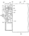
図2に示されるように、庫内温度調整装置400は、ハウジング410と、遮蔽部材420と、ヒートポンプ430とを備えている。
ハウジング410は、箱状に形成されている。ハウジング410の上部には、開口部415が形成されている。ハウジング410の第1側壁416は、コンテナ200に固定されている。ハウジング410の第1側壁416の内面には、遮蔽部材420が固定されている。遮蔽部材420は、箱状に形成されている。遮蔽部材420は、例えば高い断熱性を有する樹脂材料により形成されている。ハウジング410の第1側壁416の内面と遮蔽部材420の内面とにより囲まれる空間により、庫内側空気通路418が形成されている。また、ハウジング410の内部空間における庫内側空気通路418を除く部分により、庫外側空気通路419が形成されている。
ハウジング410の第1側壁416には、庫内側空気通路418からコンテナ200の内部空間に貫通する庫内側貫通孔413,414が形成されている。庫内側貫通孔413は、庫内側空気通路418におけるコンテナ200の天井面202側の端部に位置している。庫内側貫通孔414は、庫内側空気通路418におけるコンテナ200の底面203側の端部に位置している。これらの庫内側貫通孔413,414により、コンテナ200の内部空間と庫内側空気通路418とが連通されている。庫内側空気通路418には、庫内側熱交換器435と、庫内側ファン438とが設けられている。庫内側ファン438は、庫内側熱交換器435よりもコンテナ200の天井面202側に配置されている。庫内側ファン438は、庫内側空気通路418を流れる空気を庫内側熱交換器435に送風する。庫内側熱交換器435は、内部を流れる熱媒体と、庫内側空気通路418を流れる空気との間で熱交換を行う。すなわち、庫内側熱交換器435は、内部を流れる熱媒体と、コンテナ200の内部の空気との間で熱交換を行う。
ハウジング410における第1側壁416に対向する第2側壁417には、庫外側空気通路419からハウジング410の外部に貫通する庫外側貫通孔411,412が形成されている。これらの庫外側貫通孔411,412により、コンテナ200の外部空間と庫外側空気通路419とが連通されている。庫外側貫通孔411,412には、熱交換部材433a,433bがそれぞれ配置されている。庫外側空気通路419におけるハウジング410の開口部415には、熱交換部材433c及び庫外側ファン436が配置されている。庫外側ファン436は、熱交換部材433cよりもコンテナ200の天井面202側に配置されている。換言すれば、庫外側ファン436は熱交換部材433cよりも鉛直方向上方側に配置されている。熱交換部材433a,433b,433cにより庫外側熱交換器433が構成されている。すなわち、庫外側熱交換器433は、分離された3つの熱交換部材433a,433b,433cにより構成されている。具体的には、分離された3つの熱交換部材433a,433b,433cは、図2に示されるように分割され、且つ離れて配置されている。庫外側ファン436は、庫外側空気通路419を流れる空気を熱交換部材433a,433b,433cに送風する。庫外側熱交換器433は、内部を流れる熱媒体と、庫外側空気通路419を流れる空気との間で熱交換を行う。すなわち、庫外側熱交換器433は、内部を流れる熱媒体と、コンテナ200の外部の空気との間で熱交換を行う。
次に、熱交換部材433a,433b,433c及び庫内側熱交換器435の構造について詳しく説明する。なお、熱交換部材433a,433b,433c及び庫内側熱交換器435は基本的には同一構造を有しているため、ここでは代表して熱交換部材433aの構造について説明する。
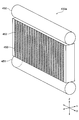
図3に示されるように、熱交換部材433aは、ヘッダタンク450,451と、チューブ452と、フィン453とを備えている。
ヘッダタンク450,451は、矢印Xで示される方向に平行に配置されている。ヘッダタンク450,451は、矢印Zで示される方向に互いに離間して配置されている。ヘッダタンク450とヘッダタンク451との間には、複数のチューブ452が矢印Xで示される方向に隙間を隔てて積層配置されている。以下では、矢印Xで示される方向を「チューブ積層方向」と称する。ヘッダタンク450,451は、各チューブ452へ熱媒体を分配する機能、及び各チューブ452を流れ終えた熱媒体を回収する機能を有している。
チューブ452は、矢印Zで示される方向に長手方向を有する扁平状の細長い管である。以下では、矢印Zで示される方向を「チューブ長手方向」と称する。チューブ452の長手方向Zの両端部は、ヘッダタンク450,451にそれぞれ接続されている。チューブ452内の熱媒体の通路は、ヘッダタンク450,451の内部通路に連通されている。隣り合うチューブ452間に形成される隙間には、矢印Yで示される方向に空気が流れる。以下では、矢印Yで示される方向を「空気流通方向」と称する。空気流通方向Yは、チューブ積層方向X及びチューブ長手方向Zの両者に直交する方向である。
フィン453は、隣り合うチューブ452,452間の隙間に配置されている。フィン453は、薄く長い金属板をつづら折りに加工することにより形成される、いわゆるコルゲートフィンである。フィン453は、伝熱面積を増やすことにより熱交換部材433aの熱交換性能を高める機能を有している。
熱交換部材433aでは、チューブ452の内部を熱媒体が流れる際、チューブ452の外部を流れる空気と熱媒体との間で熱交換が行われる。熱交換部材433b,433c及び庫内側熱交換器435についても同様である。
図2に示されるように、熱交換部材433a,433bは、空気流通方向が図中の矢印Ya,Ybで示される方向となるように配置されている。すなわち、熱交換部材433a,433bは、空気流通方向がコンテナ200の天井面202に平行な方向、換言すれば水平方向に平行な方向となるように配置されている。
熱交換部材433cは、空気流通方向が図中の矢印Ycで示される方向となるように配置されている。すなわち、熱交換部材433cは、空気流通方向がコンテナ200の天井面202に直交する方向、換言すれば鉛直方向に平行な方向となるように配置されている。このように、本実施形態では、熱交換部材433cの空気流通方向である所定方向が、コンテナ200の天井面202に略直交する方向、換言すれば略鉛直方向に設定されている。
なお、本実施形態では、熱交換部材433a,433bが直立熱交換部材に相当し、熱交換部材433cが傾斜熱交換部材に相当する。
庫内側熱交換器435は、空気流通方向が図中の矢印Ydで示される方向となるように配置されている。すなわち、庫内側熱交換器435は、空気流通方向がコンテナ200の天井面202に交差する方向、換言すれば水平方向に交差する方向となるように配置されている。
次に、ヒートポンプ430の構造について詳しく説明する。
図4に示されるように、ヒートポンプ430は、熱交換部材433a,433b,433cにより構成される庫外側熱交換器433、庫内側熱交換器435、庫外側ファン436、庫内側ファン438に加え、圧縮機431、四方弁432、及び膨張弁434を有している。これらの要素は、配管440を介して環状に接続されている。配管440には熱媒体が流れている。
圧縮機431は、トレーラ100のエンジンの動力、もしくは内蔵された電動モータの動力に基づいて駆動する。圧縮機431は、熱媒体を吸引して圧縮し、高温高圧の熱媒体を吐出する。
四方弁432は、熱媒体の流れ方向を切り替える。具体的には、四方弁432は、図中の実線の流路と、破線の流路とに切り替え可能になっている。四方弁432の流路が実線の流路に設定されている場合、圧縮機431の吸入口に庫内側熱交換器435が接続され、圧縮機431の吐出口に庫外側熱交換器433が接続される。これに対し、四方弁432の流路が破線の流路に設定されている場合、圧縮機431の吸入口に庫外側熱交換器433が接続され、圧縮機431の吐出口に庫内側熱交換器435が接続される。
膨張弁434は、熱媒体を急激に膨張させ、低温低圧の熱媒体を生成する。
庫外側ファン436は、庫外側ファンモータ437から伝達される動力に基づき駆動する。庫内側ファン438は、庫内側ファンモータ439から伝達される動力に基づき駆動する。
このヒートポンプ430では、四方弁432の流路が実線の流路に設定されている場合、図中に実線の矢印で示される方向に熱媒体が流れる。すなわち、熱媒体は、圧縮機431、庫外側熱交換器433、膨張弁434、庫内側熱交換器435の順で流れる。この場合、庫外側熱交換器433は凝縮器として機能し、庫内側熱交換器435は蒸発器として機能する。すなわち、庫外側熱交換器433は、庫外側空気通路419を流れる空気と、圧縮機431により圧縮された高温高圧の熱媒体との間で熱交換を行うことにより、熱媒体の熱をコンテナ200の外部に放熱する。また、庫内側熱交換器435は、庫内側空気通路418を流れる空気と、膨張弁434により生成された低温低圧の熱媒体との間で熱交換を行うことにより、コンテナ200の内部の空気を冷却する。以下では、庫内側熱交換器435を蒸発器として用いるヒートポンプ430の運転状態を冷却運転と称する。
また、ヒートポンプ430では、四方弁432の流路が破線の流路に設定されている場合、図中に破線の矢印で示される方向に熱媒体が流れる。すなわち、熱媒体は、圧縮機431、庫内側熱交換器435、膨張弁434、庫外側熱交換器433の順で流れる。この場合、庫外側熱交換器433は蒸発器として機能し、庫内側熱交換器435は凝縮器として機能する。すなわち、庫外側熱交換器433は、庫外側空気通路419を流れる空気と、膨張弁434により生成された低温低圧の熱媒体との間で熱交換を行うことにより、コンテナ200の外部の空気の熱を熱媒体に吸熱させる。また、庫内側熱交換器435は、庫内側空気通路418を流れる空気と、圧縮機431により生成された高温高圧の熱媒体との間で熱交換を行うことにより、コンテナ200の内部の空気を加熱する。以下では、庫内側熱交換器435を凝縮器として用いるヒートポンプ430の運転状態を加温運転と称する。
このように、本実施形態の庫内温度調整装置400では、庫内側熱交換器435がヒートポンプ430の蒸発器及び凝縮器のいずれか一方として機能し、庫外側熱交換器433がヒートポンプ430の蒸発器及び凝縮器のいずれか他方として機能する。本実施形態の庫内温度調整装置400では、ヒートポンプ430を利用してコンテナ200の冷却及び加熱を行うことにより、コンテナ200内の温度を調整する。
次に、庫内温度調整装置400の電気的な構成について説明する。
図5に示されるように、庫内温度調整装置400は、ECU(Electronic Control Unit)460と、庫内温度センサ461と、温度設定スイッチ462とを備えている。本実施形態では、ECU460が制御部に相当する。
庫内温度センサ461は、コンテナ200内の温度を検出し、検出した温度に基づく検出信号を出力する。庫内温度センサ461の検出信号は、ECU460に取り込まれている。ECU460は、庫内温度センサ461の検出信号に基づいてコンテナ200内の検出温度を取得し、コンテナ200内の温度に基づいて圧縮機431、四方弁432、庫外側ファンモータ437、及び庫内側ファンモータ439の駆動を制御する。
具体的には、ECU460は、トレーラの運転者等により温度設定スイッチ462を通じて設定される目標温度と、コンテナ200内の検出温度とを比較する。ECU460は、コンテナ200内の検出温度が目標温度よりも高い場合には、ヒートポンプ430を冷却運転させるべく、圧縮機431及び四方弁432を駆動させる。また、ECU460は、コンテナ200内の検出温度が目標温度よりも高い場合には、ヒートポンプ430を加温運転させるべく、圧縮機431及び四方弁432を制御する。
ECU460は、庫内側ファンモータ439を駆動させることにより、庫内側熱交換器435に、図2に実線で示される方向の空気流を形成する。すなわち、ECU460は、庫内側貫通孔414から庫内側熱交換器435を通過して庫内側貫通孔413へと流れる空気流を形成する。
ECU460は、ヒートポンプ430を冷却運転又は加温運転させている場合、庫外側ファンモータ437を駆動させることにより、庫外側熱交換器433に、図2に実線で示される方向の空気流を形成する。すなわち、ECU460は、庫外側空気通路419内から熱交換部材433cを通過してハウジング410の開口部415から外部へと流れる空気流を形成する。これにより、車両走行風によりコンテナ200の外部から熱交換部材433a,433bを通過して庫内側空気通路418に進入した空気が熱交換部材433cを通過することになる。このように車両走行風を利用することにより、熱交換部材433a,433b,433cを通過する空気の風量を増加させることができるため、熱交換部材433a,433b,433cの熱交換率を向上させることができる。
ところで、ヒートポンプ430を加温運転させている場合、庫外側熱交換器433が蒸発器として機能するため、庫外側熱交換器433に凝縮水が発生する。そのため、トレーラ100が寒冷地を走行しているような場合、庫外側熱交換器433により生成される凝縮水により、庫外側熱交換器433に霜が発生する可能性がある。この霜は庫外側熱交換器433の熱交換性能を低下させるため、除去することが望ましい。
そこで、本実施形態のECU460は、ヒートポンプ430を加温運転させている期間に、一時的にヒートポンプ430を冷却運転させて庫外側熱交換器433を凝縮器として機能させることにより、庫外側熱交換器433を暖める、いわゆる除霜運転を定期的に行う。また、ECU460は、除霜運転の終了時に、庫外側ファン436の回転方向を逆転させる。
次に、図6を参照して、ECU460による庫外側ファン436の駆動制御について詳しく説明する。なお、ECU460は、除霜運転の開始時に図6に示される処理を実行する。
図6に示されるように、ECU460は、まず、ステップS1の処理として、除霜運転が終了したか否かを判断する。ECU460は、ステップS1の処理で肯定判断した場合(S1:YES)、ステップS2の処理として、庫外側ファン436の回転方向が逆転するように庫外側ファンモータ437を駆動させる。ECU460は、ステップS2に続くステップS3の処理として、庫外側ファン436の回転方向の逆転を開始した時点から所定時間が経過したか否かを判断する。ECU460は、ステップS3の処理で否定判断した場合には(S3:NO)、ステップS2の処理に戻り、庫外側ファン436の回転方向を逆転させた状態を維持する。
ECU460は、ステップS3の処理で肯定判断した場合(S3:YES)、すなわち庫外側ファン436の回転方向の逆転を開始した時点から所定時間が経過した場合には、庫外側ファン436の回転方向を戻す。
次に、本実施形態の庫内温度調整装置400の動作例について説明する。
ECU460が除霜運転を行うと、庫外側熱交換器433に発生した霜が溶けて水滴が発生する。この際、図2に示されるように、熱交換部材433cは、空気流通方向が鉛直方向に平行な方向となるように配置されているため、熱交換部材433cに発生した水滴が重力により鉛直方向下方へと流れ易くなっている。よって、熱交換部材433cの排水性を向上させることができる。
また、ECU460は、除霜運転の終了時に、庫外側ファン436を所定時間だけ逆回転させる。これにより、熱交換部材433cには、図2に破線で示される方向の空気流が形成される。すなわち、ハウジング410の開口部415から熱交換部材433cを通過して庫内側空気通路418へと流れる空気流が形成される。これにより、熱交換部材433cに発生した水滴には、庫外側ファン436の風力により鉛直方向下方側へ向かう方向の力が働くため、熱交換部材433cに発生した水滴が鉛直方向下方へと更に流れ易くなる。よって、熱交換部材433cの排水性を更に向上させることができる。
以上説明した本実施形態の庫内温度調整装置400によれば、以下の(1)~(4)に示される作用及び効果を得ることができる。
(1)庫外側熱交換器433は、分離された3つの熱交換部材433a,433b,433cにより構成されている。このような構成によれば、庫外側熱交換器433の配置の自由度を向上させることができる。よって、本実施形態の庫内温度調整装置400のように、庫外側空気通路419において庫外側熱交換器433を配置可能なスペースが限られている場合でも、高い排水性が得られるように熱交換部材433cを配置することができる。結果的に、庫外側熱交換器433全体としての排水性を向上させることができる。これにより、ヒートポンプ430の冷却運転を再開した際に、熱交換部材433cに霜が再発生し難くなるため、庫外側熱交換器433全体の熱交換性能を維持することができる。
(2)熱交換部材433cは、空気流通方向がコンテナ200の天井面202と直交する方向となるように配置されている。これにより、熱交換部材433cに発生する水滴が鉛直方向下方へと流れ易くなるため、庫外側熱交換器433の排水性を更に向上させることができる。
(3)庫外側熱交換器433が蒸発器として機能している場合、膨張弁434により生成された低温低圧の熱媒体は、図4に破線で示されるように、熱交換部材433c、熱交換部材433a、熱交換部材433bの順で流れる。よって、熱交換部材433cは、他の熱交換部材433a,433bよりも冷却されるため、熱交換部材433cが着霜し易くなる。このように、熱交換部材433a,433bよりも排水性の高い熱交換部材433cに着霜させれば、除霜により発生する水滴が排出され易くなる。これにより、庫外側熱交換器433全体で見たときに、除霜により発生する水滴が庫外側熱交換器433に保水され難くなるため、ヒートポンプ430の冷却運転を再開した際に、熱交換部材433cに霜が更に発生し難くなる。よって、庫外側熱交換器433全体の熱交換性能をより的確に維持することができる。
(4)ECU460は、除霜運転の終了時に、除霜運転により熱交換部材433cに発生した水滴を除去すべく、庫外側ファン436の回転方向を逆転させる。これにより、熱交換部材433cの排水性を更に向上させることができるため、結果的に庫外側熱交換器433全体の熱交換性能をより的確に維持することができる。
なお、上記実施形態は、以下の形態にて実施することもできる。
熱交換部材433a,433b,433cの配置は適宜変更可能である。例えば図7に示されるように、熱交換部材433cは、空気流通方向がコンテナ200の天井面202と交差するように傾斜して配置されていてもよい。また、庫外側熱交換器433を構成する熱交換部材の数も適宜変更可能である。要は、庫外側熱交換器433は、空気流通方向がコンテナ200の天井面202と交差する所定方向に設定された傾斜熱交換部材を有していればよい。
ECU460は、除霜運転の実行中、又は除霜運転の終了後に、庫外側ファン436の回転方向を逆転させる処理を実行してもよい。
ECU460は、庫外側ファン436の回転方向を逆転させる処理を実行しなくてもよい。
上記実施形態の庫内温度調整装置400は、トレーラ100のコンテナ200に限らず、航空機のコンテナ等、他のコンテナにも適用することが可能である。
ECU460が提供する手段及び機能は、実体的な記憶装置に記憶されたソフトウェア及びそれを実行するコンピュータ、ソフトウェアのみ、ハードウェアのみ、あるいはそれらの組み合わせにより提供することができる。ECU460が提供する手段及び機能のうち片方を、実体的な記憶装置に記憶されたソフトウェア及びそれを実行するコンピュータ、ソフトウェアのみ、ハードウェアのみ、あるいはそれらの組み合わせにより提供してもよい。例えばECU460がハードウェアである電子回路により提供される場合、それは多数の論理回路を含むデジタル回路、またはアナログ回路により提供することができる。
本開示は上記の具体例に限定されるものではない。すなわち、上記の具体例に、当業者が適宜設計変更を加えたものも、本開示の特徴を備えている限り、本開示の範囲に包含される。例えば、前述した各具体例が備える各要素及びその配置、材料、条件、形状、サイズ等は、例示したものに限定されるわけではなく適宜変更することができる。また、前述した実施形態が備える各要素は、技術的に可能な限りにおいて組み合わせることができ、これらを組み合わせたものも本開示の特徴を含む限り本開示の範囲に包含される。
本開示は、実施例に準拠して記述されたが、本開示は当該実施例や構造に限定されるものではないと理解される。本開示は、様々な変形例や均等範囲内の変形をも包含する。加えて、様々な組み合わせや形態、さらには、それらに一要素のみ、それ以上、あるいはそれ以下、を含む他の組み合わせや形態をも、本開示の範疇や思想範囲に入るものである。
Claims (6)
- コンテナ(200)内の温度を調整する庫内温度調整装置(400)であって、
ヒートポンプ(430)と、
前記ヒートポンプの蒸発器及び凝縮器のいずれか一方として機能し、前記コンテナの内部の空気と熱媒体との間で熱交換を行う庫内側熱交換器(435)と、
前記蒸発器及び前記凝縮器のいずれか他方として機能し、前記コンテナの外部の空気と前記熱媒体との間で熱交換を行う庫外側熱交換器(433)と、を備え、
前記庫外側熱交換器は、分離された複数の熱交換部材(433a,433b,433c)により構成されている
庫内温度調整装置。 - 前記複数の熱交換部材には、空気流通方向が前記コンテナの天井面と交差する所定方向に設定された傾斜熱交換部材(433c)が含まれている
請求項1に記載の庫内温度調整装置。 - 前記所定方向は、前記コンテナの天井面と略直交する方向である
請求項2に記載の庫内温度調整装置。 - 前記複数の熱交換部材には、空気流通方向が前記コンテナの天井面と平行な方向に設定された直立熱交換部材(433a,433b)が更に含まれ、
前記熱媒体は、前記庫外側熱交換器が前記蒸発器として機能している際に、前記傾斜熱交換部材から前記直立熱交換部材へと流れる
請求項2または3に記載の庫内温度調整装置。 - 鉛直方向において、前記傾斜熱交換部材よりも前記コンテナの天井面に近い位置に設けられ、前記傾斜熱交換部材に空気を送風する庫外側ファン(436)と、
前記ヒートポンプ及び前記庫外側ファンの駆動を制御する制御部(460)と、を更に備え、
前記制御部は、
前記庫内側熱交換器が前記蒸発器として機能するように前記ヒートポンプを駆動させる冷却運転と、
前記庫内側熱交換器が前記凝縮器として機能するように前記ヒートポンプを駆動させる加温運転と、
前記加温運転の実行中に、一時的に前記庫外側熱交換器が前記凝縮器として機能するように前記ヒートポンプを駆動させる除霜運転と、を実行するとともに、
前記冷却運転及び前記加温運転の際には、前記傾斜熱交換部材を前記コンテナの天井面へ向かって空気が流れるように前記庫外側ファンを駆動させるとともに、
前記除霜運転により前記傾斜熱交換部材に発生する水滴を除去すべく、前記傾斜熱交換部材を前記コンテナの底面に向かって空気が流れるように前記庫外側ファンの回転方向を逆転させる
請求項2~4のいずれか一項に記載の庫内温度調整装置。 - 前記制御部は、
前記冷却運転時には、前記熱媒体が、前記圧縮機、前記庫外側熱交換器、前記庫内側熱交換器の順に流れるように、前記圧縮機と前記四方弁を制御し、
前記加温運転時には、前記熱媒体が、前記圧縮機、前記庫内側熱交換器、前記庫外側熱交換器の順に流れるように、前記圧縮機と前記四方弁を制御し、
前記除霜運転時には、前記熱媒体が、前記圧縮機、前記庫外側熱交換器、前記庫内側熱交換器の順に流れるように、前記圧縮機と前記四方弁を制御する、
請求項5に記載の庫内温度調整装置。
Priority Applications (2)
| Application Number | Priority Date | Filing Date | Title |
|---|---|---|---|
| US15/776,323 US10670313B2 (en) | 2015-11-18 | 2016-11-04 | Internal temperature adjusting device |
| CN201680066762.9A CN108291761B (zh) | 2015-11-18 | 2016-11-04 | 库内温度调整装置 |
Applications Claiming Priority (2)
| Application Number | Priority Date | Filing Date | Title |
|---|---|---|---|
| JP2015225504A JP6414029B2 (ja) | 2015-11-18 | 2015-11-18 | 庫内温度調整装置 |
| JP2015-225504 | 2015-11-18 |
Publications (1)
| Publication Number | Publication Date |
|---|---|
| WO2017086183A1 true WO2017086183A1 (ja) | 2017-05-26 |
Family
ID=58718718
Family Applications (1)
| Application Number | Title | Priority Date | Filing Date |
|---|---|---|---|
| PCT/JP2016/082744 Ceased WO2017086183A1 (ja) | 2015-11-18 | 2016-11-04 | 庫内温度調整装置 |
Country Status (4)
| Country | Link |
|---|---|
| US (1) | US10670313B2 (ja) |
| JP (1) | JP6414029B2 (ja) |
| CN (1) | CN108291761B (ja) |
| WO (1) | WO2017086183A1 (ja) |
Families Citing this family (3)
| Publication number | Priority date | Publication date | Assignee | Title |
|---|---|---|---|---|
| SE541965C2 (en) * | 2016-07-12 | 2020-01-14 | Es Energy Save Holding Ab | Heat pump apparatus module |
| WO2019215813A1 (ja) * | 2018-05-08 | 2019-11-14 | 三菱電機株式会社 | 空気調和機 |
| CN114684502A (zh) * | 2022-03-28 | 2022-07-01 | 山东鲁烟莱州印务有限公司 | 一种环保型胶印油墨保温装置 |
Citations (4)
| Publication number | Priority date | Publication date | Assignee | Title |
|---|---|---|---|---|
| JPH0634256A (ja) * | 1992-07-17 | 1994-02-08 | Mitsubishi Heavy Ind Ltd | 熱交換装置及びこれを備えたコンテナ用冷凍ユニット |
| JPH0628576U (ja) * | 1992-09-11 | 1994-04-15 | 三菱重工業株式会社 | コンテナ用冷凍ユニット |
| JP2004286363A (ja) * | 2003-03-24 | 2004-10-14 | Toshiba Kyaria Kk | 冷凍車 |
| JP2013217506A (ja) * | 2012-04-04 | 2013-10-24 | Mitsubishi Electric Corp | 冷凍サイクル装置 |
Family Cites Families (6)
| Publication number | Priority date | Publication date | Assignee | Title |
|---|---|---|---|---|
| JP3038345U (ja) * | 1996-12-03 | 1997-06-20 | 株式会社 六甲海商 | 冷凍コンテナ |
| JP2002340449A (ja) * | 2001-05-15 | 2002-11-27 | Mitsubishi Heavy Ind Ltd | 冷凍ユニット |
| JP2007309608A (ja) * | 2006-05-19 | 2007-11-29 | Daikin Ind Ltd | トレーラー用冷凍装置 |
| JP2015010766A (ja) | 2013-06-28 | 2015-01-19 | 株式会社デンソー | ヒートポンプサイクル用の室外機 |
| JP6239368B2 (ja) * | 2013-12-17 | 2017-11-29 | 三菱重工サーマルシステムズ株式会社 | 輸送用冷凍ユニット |
| JP6320567B2 (ja) * | 2015-01-13 | 2018-05-09 | 三菱電機株式会社 | 空気調和装置 |
-
2015
- 2015-11-18 JP JP2015225504A patent/JP6414029B2/ja not_active Expired - Fee Related
-
2016
- 2016-11-04 CN CN201680066762.9A patent/CN108291761B/zh not_active Expired - Fee Related
- 2016-11-04 WO PCT/JP2016/082744 patent/WO2017086183A1/ja not_active Ceased
- 2016-11-04 US US15/776,323 patent/US10670313B2/en not_active Expired - Fee Related
Patent Citations (4)
| Publication number | Priority date | Publication date | Assignee | Title |
|---|---|---|---|---|
| JPH0634256A (ja) * | 1992-07-17 | 1994-02-08 | Mitsubishi Heavy Ind Ltd | 熱交換装置及びこれを備えたコンテナ用冷凍ユニット |
| JPH0628576U (ja) * | 1992-09-11 | 1994-04-15 | 三菱重工業株式会社 | コンテナ用冷凍ユニット |
| JP2004286363A (ja) * | 2003-03-24 | 2004-10-14 | Toshiba Kyaria Kk | 冷凍車 |
| JP2013217506A (ja) * | 2012-04-04 | 2013-10-24 | Mitsubishi Electric Corp | 冷凍サイクル装置 |
Also Published As
| Publication number | Publication date |
|---|---|
| US20180356135A1 (en) | 2018-12-13 |
| CN108291761B (zh) | 2020-07-14 |
| JP2017096507A (ja) | 2017-06-01 |
| CN108291761A (zh) | 2018-07-17 |
| US10670313B2 (en) | 2020-06-02 |
| JP6414029B2 (ja) | 2018-10-31 |
Similar Documents
| Publication | Publication Date | Title |
|---|---|---|
| US10744850B2 (en) | Heat pump system for vehicle | |
| CN111791671B (zh) | 车载调温装置 | |
| US8109327B2 (en) | Temperature control system having heat exchange modules with indirect expansion cooling and in-tube electric heating | |
| CN108351189A (zh) | 疏水性换热器 | |
| JP2003097857A (ja) | 冷房サイクル | |
| JP5503085B2 (ja) | 電動輸送機器の内部空間および/または少なくとも1つの部品の空調装置および空調方法 | |
| JP6414029B2 (ja) | 庫内温度調整装置 | |
| KR20180085958A (ko) | 차량용 열관리 시스템 | |
| US20190084378A1 (en) | Cold energy storage evaporator and vehicle refrigeration cycle device provided with same | |
| JP5264442B2 (ja) | 車両用空調装置 | |
| JP6888904B2 (ja) | 冷凍サイクルシステム | |
| JP6729269B2 (ja) | 冷蔵庫とその制御方法 | |
| KR102181352B1 (ko) | 배터리 공조 모듈 및 시스템 | |
| JP2004278948A (ja) | カーエアコン用熱交換器 | |
| WO2010150469A1 (ja) | 輸送用冷凍装置 | |
| JP6451212B2 (ja) | 冷却装置 | |
| JP2005053474A (ja) | 車両用冷却ファンの制御装置及び制御方法 | |
| CN108928210A (zh) | 特别用于电动车辆的车辆空调系统 | |
| JP2013185762A (ja) | 冷媒サイクル装置 | |
| JP2009281659A (ja) | 冷凍サイクル装置 | |
| JP6984295B2 (ja) | 車両 | |
| US10634394B2 (en) | Air conditioner outdoor unit including heat exchange apparatus | |
| JP2015098949A (ja) | 熱交換システム | |
| CN107036337B (zh) | 再生热交换器疏水性涂层的方法 | |
| JP2005300106A (ja) | ヒーティングタワーの除霜方法および水冷式ヒートポンプシステム |
Legal Events
| Date | Code | Title | Description |
|---|---|---|---|
| 121 | Ep: the epo has been informed by wipo that ep was designated in this application |
Ref document number: 16866185 Country of ref document: EP Kind code of ref document: A1 |
|
| NENP | Non-entry into the national phase |
Ref country code: DE |
|
| 122 | Ep: pct application non-entry in european phase |
Ref document number: 16866185 Country of ref document: EP Kind code of ref document: A1 |