WO2017086083A1 - 電力伝送用アンテナ装置、電子機器および電力伝送システム - Google Patents
電力伝送用アンテナ装置、電子機器および電力伝送システム Download PDFInfo
- Publication number
- WO2017086083A1 WO2017086083A1 PCT/JP2016/081035 JP2016081035W WO2017086083A1 WO 2017086083 A1 WO2017086083 A1 WO 2017086083A1 JP 2016081035 W JP2016081035 W JP 2016081035W WO 2017086083 A1 WO2017086083 A1 WO 2017086083A1
- Authority
- WO
- WIPO (PCT)
- Prior art keywords
- coil
- power transmission
- coupling
- coupling portion
- power
- Prior art date
- Legal status (The legal status is an assumption and is not a legal conclusion. Google has not performed a legal analysis and makes no representation as to the accuracy of the status listed.)
- Ceased
Links
Images





Classifications
-
- H—ELECTRICITY
- H01—ELECTRIC ELEMENTS
- H01Q—ANTENNAS, i.e. RADIO AERIALS
- H01Q7/00—Loop antennas with a substantially uniform current distribution around the loop and having a directional radiation pattern in a plane perpendicular to the plane of the loop
-
- H—ELECTRICITY
- H02—GENERATION; CONVERSION OR DISTRIBUTION OF ELECTRIC POWER
- H02J—ELECTRIC POWER NETWORKS; CIRCUIT ARRANGEMENTS OR SYSTEMS FOR SUPPLYING OR DISTRIBUTING ELECTRIC POWER; SYSTEMS FOR STORING ELECTRIC ENERGY
- H02J50/00—Circuit arrangements or systems for wireless supply or distribution of electric power
- H02J50/10—Circuit arrangements or systems for wireless supply or distribution of electric power using inductive coupling
-
- H—ELECTRICITY
- H02—GENERATION; CONVERSION OR DISTRIBUTION OF ELECTRIC POWER
- H02J—ELECTRIC POWER NETWORKS; CIRCUIT ARRANGEMENTS OR SYSTEMS FOR SUPPLYING OR DISTRIBUTING ELECTRIC POWER; SYSTEMS FOR STORING ELECTRIC ENERGY
- H02J50/00—Circuit arrangements or systems for wireless supply or distribution of electric power
- H02J50/10—Circuit arrangements or systems for wireless supply or distribution of electric power using inductive coupling
- H02J50/12—Circuit arrangements or systems for wireless supply or distribution of electric power using inductive coupling of the resonant type
Definitions
- the present invention relates to a system for transmitting power wirelessly, and more particularly, to a power transmission antenna device used in the system, an electric device including the antenna device, and a power transmission system including a power transmission device and a power receiving device.
- Patent Document 1 that is an example of a wireless power transmission system (Wireless Power Transfer: WPT) discloses a magnetic field type power transmission system.
- a relay LC resonance circuit including another inductor (coil) is provided between a power transmission coil and a power reception coil, so that power can be supplied to a more distant place.
- the coupling coefficient between the power transmission coil and the power reception coil greatly affects the transmission efficiency of active power. Therefore, simply disposing another coil between the power transmission coil and the power reception coil may not allow efficient power transmission from the power transmission device having the power transmission coil to the power reception device having the power reception coil.
- An object of the present invention is to provide a power transmission antenna device capable of efficiently transmitting power wirelessly, an electric device including the power transmission antenna device, and a power transmission system.
- An antenna device for power transmission includes: A first coil to which a power transmission circuit or a power reception circuit of a wireless power transmission system is connected; A first coupling portion having a coiled conductor coupled to the first coil; A second coupling portion coupled to the second coil of the counterpart device and having a coiled conductor larger than the first coupling portion; A coil antenna having a connection portion connecting the first coupling portion and the second coupling portion; The formation area of the first coil and the formation area of the first coupling portion overlap in a plan view of the coil opening of the first coil and the first coupling portion.
- the coupling coefficient between the first coil (the power transmission coil when the own apparatus is a power transmission apparatus, the power reception coil when the own apparatus is a power reception apparatus) and the first coupling unit and the second coil can also be increased. As a result, power transmission efficiency can be increased.
- the first coupling portion overlaps with the coil opening of the second coupling portion, and the circulation direction of the current flowing through the first coupling portion and the second coupling portion
- the first coupling portion and the second coupling portion are connected by the connection portion so that the circulation directions of the currents flowing through the first and second coupling portions are opposite to each other.
- the magnetic flux generated by the current flowing through the first coupling portion and the magnetic flux generated by the current flowing through the second coupling portion in the vicinity of the connection portion connecting the first coupling portion and the second coupling portion are not offset. Therefore, the effective coil opening of the second coupling portion that contributes to the coupling with the second coil (coil antenna of the counterpart device) can be increased, and the coupling coefficient between the second coupling portion and the second coil can be increased.
- the position of the first coupling portion is different from the position of the connection portion in the coil winding axis direction of the first coupling portion. That is, the first coupling portion and the connection portion are not on the same plane, and the first coupling portion and the connection portion are three-dimensionally formed.
- the connecting portion becomes acute, the effective coil opening of the second coupling portion can be increased, and three-dimensionally, the connection portion between the first coupling portion and the second coupling portion.
- the sharp bending of the connecting portion is eliminated, and disconnection of the connecting portion can be prevented.
- the first coupling part in the plan view of the coil opening of the first coupling part, is disposed outside the coil opening of the second coupling part, and the current flows through the first coupling part.
- the first coupling portion and the second coupling portion may be connected by the connection portion so that the circulation direction of the current and the circulation direction of the current flowing through the second coupling portion are opposite to each other.
- the magnetic flux generated by the current flowing through the first coupling portion and the magnetic flux generated by the current flowing through the second coupling portion in the vicinity of the connection portion connecting the first coupling portion and the second coupling portion are not canceled out. Therefore, the effective coil opening of the second coupling portion that contributes to the coupling with the second coil (coil antenna of the counterpart device) can be increased, and the coupling coefficient between the second coupling portion and the second coil can be increased.
- any one of the above (1) to (4) it is preferable that a capacitor connected to the first coil is provided. As a result, even if the coupling between the first coil and the first coupling portion and the coupling between the second coil and the second coupling portion are reduced, high-efficiency power transmission can be performed with a low driving voltage.
- any one of (1) to (5) it is preferable that a capacitor connected to the first coupling portion is provided. As a result, even if the coupling between the first coil and the first coupling portion and the coupling between the second coil and the second coupling portion are reduced, high-efficiency power transmission can be performed with a low driving voltage.
- any one of (1) to (6) it is preferable that a capacitor connected to the second coupling portion is provided. As a result, even if the coupling between the first coil and the first coupling portion and the coupling between the second coil and the second coupling portion are reduced, high-efficiency power transmission can be performed with a low driving voltage.
- the electronic device of the present invention A power transmission circuit or a power reception circuit, and a power transmission antenna device to which the power transmission circuit or the power reception circuit is connected,
- the power transmission antenna device includes: A first coil to which the power transmission circuit or the power reception circuit is connected; A first coupling part having a coiled conductor coupled to the first coil, a second coupling part coupled to the second coil of the counterpart device and having a coiled conductor having a larger formation area than the first coupling part; A coil antenna having a connection portion connecting the first coupling portion and the second coupling portion; The formation area of the first coil and the formation area of the first coupling portion overlap in a plan view of the coil opening of the first coil and the first coupling portion.
- the above configuration constitutes an electronic device with high power transmission efficiency.
- the power transmission system of the present invention includes: Including a power transmission device and a power reception device,
- the power receiving device includes a power receiving circuit and a power transmission antenna device connected to the power receiving device.
- the power transmission device includes a power transmission circuit and a second coil connected to the power transmission circuit,
- the power transmission antenna device includes: A first coil to which the power receiving circuit is connected; A first coupling portion having a coiled conductor coupled to the first coil; a second coupling portion coupled to the second coil and having a coiled conductor having a larger formation area than the first coupling portion;
- a coil antenna having a connecting portion for connecting the first connecting portion and the second connecting portion; The formation area of the first coil and the formation area of the first coupling portion overlap in a plan view of the coil opening of the first coil and the first coupling portion.
- the above configuration constitutes a wireless power transmission system with high power transmission efficiency.
- the power transmission system of the present invention includes: Including a power transmission device and a power reception device,
- the power receiving device includes a power receiving circuit and a second coil connected to the power receiving circuit.
- the power transmission device includes a power transmission circuit and a power transmission antenna device connected to the power transmission device.
- the power transmission antenna device includes: A first coil to which the power transmission circuit is connected; A first coupling portion having a coiled conductor coupled to the first coil; a second coupling portion coupled to the second coil and having a coiled conductor having a larger formation area than the first coupling portion; A coil antenna having a connecting portion for connecting the first connecting portion and the second connecting portion; The formation area of the first coil and the formation area of the first coupling portion overlap in a plan view of the coil opening of the first coil and the first coupling portion.
- the above configuration constitutes a wireless power transmission system with high power transmission efficiency.
- a power transmission antenna device capable of efficiently transmitting power wirelessly, an electric device including the power transmission antenna device, and a power transmission system.
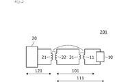
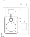
- FIG. 1 is a diagram illustrating a configuration of a power transmission antenna device 101 and a power transmission system 201 according to the first embodiment.
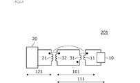
- FIG. 2 is a circuit diagram of the power transmission system 201.
- FIG. 3 is a circuit diagram of the power transmission system 201 and shows the coil polarity.
- FIG. 4A is a diagram illustrating a connection structure of the first coupling unit 31 and the second coupling unit 32 in the first embodiment
- FIG. 4B is a first coupling in the power transmission antenna device of the comparative example.
- FIG. 4 is a diagram showing a connection structure between a part 31 and a second coupling part 32.
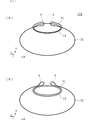
- FIG. 5 is a plan view of the antenna device 101 for power transmission.
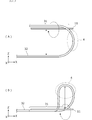
- FIG. 6A and 6B are views in which the power transmission antenna device 101 in the XY plane in FIG. 5 is viewed from the predetermined height on the Z axis in the Y axis direction.
- 7A and 7B are views of the HH portion in FIG.
- FIG. 8 is a diagram illustrating a configuration of the power transmission antenna device 102 and the power transmission system 202 according to the second embodiment.
- FIG. 9 is a diagram illustrating a connection structure of the first coupling portion 31 and the second coupling portion 32 in the second embodiment.
- FIG. 10 is a diagram illustrating a configuration of the power transmission antenna device 103 according to the third embodiment.
- FIG. 11 is a diagram illustrating a configuration of a power transmission antenna device 104 and a power transmission system including the power transmission antenna device 104 according to the fourth embodiment.
- FIG. 1 is a diagram illustrating a configuration of a power transmission antenna device and a power transmission system according to the first embodiment.
- the power transmission system 201 includes a power receiving device 111 and a power transmitting device 121.
- the power transmission device 121 includes a mounting table on which the power reception device 111 is mounted, and power transmission is performed in a state where the power reception device 111 is mounted on the mounting table of the power transmission device 121.
- FIG. 1 is a schematic plan view in a state where the power receiving device 111 is mounted on the mounting table of the power transmitting device 121.
- the power receiving device 111 includes a power transmission antenna device 101 and a power receiving circuit 10.
- the power transmission device 121 includes a second coil 21 for power transmission and a power transmission circuit 20.
- the power transmission antenna device 101 includes the first coil 11, the first coupling unit 31, the second coupling unit 32, and the connection unit 4 that connects the first coupling unit 31 and the second coupling unit 32.
- the first coil 11 is a multi-turn or one-turn coil, and both ends thereof are connected to the power receiving circuit 10.
- the first coupling portion 31 is a coil-shaped conductor having approximately one turn.
- the first coupling portion 31 has substantially the same diameter as the first coil 11, and the coil opening surrounded by the coiled conductor of the first coupling portion 31 and the coil opening of the first coil 11 overlap. Further, the first coupling portion 31 is disposed concentrically with the first coil 11. That is, when the coil opening of the first coil 11 and the first coupling portion 31 is viewed in plan, the formation region of the first coil 11 (the coil conductor and the coil opening of the first coil 11) and the formation region of the first coupling portion 31 ( It overlaps with the coiled conductor and coil opening of the first coupling portion 31. Therefore, the first coil 11 and the first coupling portion 31 are magnetically coupled with a high coupling coefficient.
- the second coupling part 32 has a coiled conductor larger than that of the first coupling part 31, and in this example, is a coiled conductor of almost one turn.
- the second coupling unit 32 is magnetically coupled to the second coil 21 of the power transmission device 121.
- the first coupling unit 31 and the second coupling unit 32 are connected via the connection unit 4.
- the second coil 21 of the power transmission device 121 is a multi-turn coil in this example, and both ends thereof are connected to the power transmission circuit 20.
- the second coil 21 is provided in the mounting table of the power transmission device 121.
- the formation region of the second coil 21 including the coil conductor and the coil opening of the second coil 21 is larger than the formation region of the second coupling portion 32 of the power receiving device 111. That is, the coil opening of the second coil 21 is larger than the coil opening of the second coupling portion 32 of the power receiving device 111.
- the second coupling part 32 enters the formation region of the second coil 21 in a state in which the power receiving device 111 is placed on the mounting table above the power transmitting device 121.
- FIG. 2 is a circuit diagram of the power transmission system 201. As shown in FIG. 2, the first coil 11 and the first coupling portion 31 are magnetically coupled, and the second coupling portion 32 and the second coil 21 are magnetically coupled. The first coil 11 and the second coil 21 are directly magnetically coupled.
- the power transmission circuit 20 energizes the second coil 21 with a high frequency current in the HF band such as 6.78 MHz (the lowest ISM band). As a result, a high frequency current is induced in the second coupling portion 32 and the first coupling portion 31. A high frequency current is induced in the first coil 11 by magnetic field coupling between the first coupling portion 31 and the first coil 11. A high frequency current is also induced in the first coil 11 by magnetic field coupling between the second coil 21 and the first coil 11.
- the power receiving circuit 10 is provided with a rectifying / smoothing circuit and a DC-DC converter.
- the high-frequency current induced in the first coil 11 is rectified and smoothed by the rectifying and smoothing circuit, and converted to a predetermined DC voltage by the DC-DC converter.
- the first coil 11 and the first coupling portion 31 have concentric and substantially the same diameter of the coil openings, so that the coupling coefficient of both is the first coil 11 and the second coupling portion. Higher than 32 coupling coefficients.
- the second coil 21 and the second coupling portion 32 have the same winding axis direction of the coil conductor of the first coil 11 and the winding axis direction of the coiled conductor of the first coupling portion 31. Since the ratio of the region where the formation region of 21 and the formation region of the second coupling portion 32 overlap each other is large, the coupling coefficient of both is higher than the coupling coefficient of the second coil 21 and the first coupling portion 31.
- the coupling coefficient of both is the second coil 21 and the first coupling part 31. Higher than the coupling coefficient.
- the first coil 11 is strongly coupled to the second coil 21 via the first coupling portion 31 and the second coupling portion 32.
- FIG. 3 is a circuit diagram of the power transmission system 201, and shows the coil polarity with black circles.
- the second coil 21 and the second coupling part 32, the first coil 11 and the second coil 21 have the same polarity, and the first coil 11 and the first coupling part 31 have the opposite polarity.
- the direct magnetic field coupling between the first coil 11 and the second coil 21 enhances the coupling between the first coil 11 and the first coupling portion 31. Works. As a result, the coupling between the first coil 11 and the second coil 21 can be strengthened.
- FIG. 4A is a diagram illustrating a connection structure of the first coupling portion 31 and the second coupling portion 32 in the present embodiment
- FIG. 4B is a diagram illustrating the first coupling portion 31 in the power transmission antenna device of the comparative example.
- FIG. 6 is a view showing a connection structure of the second coupling portion 32.
- the first coupling unit 31 and the first coupling unit 31 and the first coupling unit 31 are arranged such that the circulation direction of the current flowing through the first coupling unit 31 and the circulation direction of the current flowing through the second coupling unit 32 are opposite to each other. Since the two coupling portions 32 are connected, the magnetic flux generated by the current flowing through the first coupling portion 31 in the vicinity of the connection portion connecting the first coupling portion 31 and the second coupling portion 32 and the second coupling portion. The magnetic flux generated by the current flowing through 32 is not canceled out. For this reason, it is possible to suppress the bias of the magnetic field generated around the coil conductor of the second coupling portion 32 as much as possible.
- FIGS. 5, 6 ⁇ / b> A, 6 ⁇ / b> B, and 7 ⁇ / b> A, 7 ⁇ / b> B are diagrams illustrating the configuration of the connection unit 4.
- 5 is a plan view of the power transmission antenna device 101
- FIGS. 6A and 6B are views of the power transmission antenna device 101 in the XY plane in FIG. It is the figure which looked down at the direction.
- 7A and 7B are views of the HH portion in FIG.
- the power transmission antenna device shown in FIGS. 6 (A) and 7 (A) and the other power transmission antenna device shown in FIGS. 6 (B) and 7 (B) are both coil-wound in the first coupling portion 31.
- the position of the first coupling portion 31 (the height in the Z-axis direction) is different from the position of the connection portion 4 (the height in the Z-axis direction).
- the height of the first coupling portion 31 in the Z-axis direction is different from the height of the second coupling portion 32 in the Z-axis direction.
- the first coil 11 is substantially at the same height as the first coupling portion 31.
- the height of the first coupling portion 31 in the Z-axis direction and the height of the second coupling portion 32 in the Z-axis direction are substantially equal.
- the first coil 11 is substantially at the same height as the first coupling portion 31 and the second coupling portion 32.
- the position of the connecting portion (the height in the Z-axis direction) in the coil winding axis direction of the first coupling portion 31 is different from the position of the first coupling portion 31, so that there is no acute bending of the connecting portion 4.
- disconnection of the connecting portion can be prevented.
- the connection portion between the first coupling portion 31 and the second coupling portion 32 becomes acute, and the effective coil opening of the second coupling portion can be increased.
- the first coupling part 31, the second coupling part 32, and the connection part 4 can be configured by a series of conductive wires such as Cu coated with insulation instead of the conductor pattern on the substrate, the first coupling part 31, The direct current resistance of the second coupling portion 32 and the connection portion 4 can be reduced, and as a result, an increase in loss due to the provision of the first coupling portion 31, the second coupling portion 32, and the connection portion 4 can be suppressed.
- the first coil 11 and the second coupling portion 32 are separated from each other in the height direction (Z-axis direction). 2 Unnecessary coupling with the coupling portion 32 and the connection portion 4 is suppressed. In the example shown in FIG. 6B and FIG. 7B, the first coil 11 and the connection portion 4 are separated in the height direction (Z-axis direction). Unnecessary binding is suppressed. That is, in any case, cancellation due to unnecessary coupling is suppressed, and the effective coupling coefficient between the first coil 11 and the first coupling portion 31 is high.
- Second Embodiment an example of a power transmission antenna device in which the shapes of the first coupling portion and the second coupling portion are different from those in the first embodiment is shown.
- FIG. 8 is a diagram showing a configuration of the power transmission antenna device 102 and the power transmission system 202 according to the second embodiment.
- the power transmission system 202 includes a power receiving device 112 and a power transmitting device 122.
- the power receiving device 112 includes a power transmission antenna device 102 and a power receiving circuit 10.
- the power transmission device 122 includes the second coil 21 for power transmission and the power transmission circuit 20.
- the power transmission antenna device 102 includes the first coil 11, the first coupling unit 31, the second coupling unit 32, and the connection unit 4 that connects the first coupling unit 31 and the second coupling unit 32.
- the first coil 11 is a multi-turn or one-turn coil, and both ends thereof are connected to the power receiving circuit 10.
- the first coupling portion 31 is a coil-shaped conductor having approximately one turn.
- the first coupling portion 31 has substantially the same diameter as the first coil 11 and is disposed concentrically with the first coil 11. That is, when the coil openings of the first coil 11 and the first coupling portion 31 are viewed in plan, the formation region of the first coil 11 and the formation region of the first coupling portion 31 overlap.
- the first coupling part 31 is arranged outside the coil opening of the second coupling part 32, and the direction of the current flowing through the first coupling part 31 and the second coupling part 32.
- the first coupling portion 31 and the second coupling portion 32 are connected by the connection portion 4 so that the circulation directions of the currents flowing through the first and second coupling portions are opposite to each other.
- the second coupling part 32 has a coiled conductor larger than that of the first coupling part 31, and in this example, is a coiled conductor of almost one turn.
- the second coupling unit 32 is magnetically coupled to the second coil 21 of the power transmission device 121.
- the power transmission device 122 includes a mounting table on which the power receiving device 112 is mounted, and the second coil 21 is provided in the mounting table.
- the coil opening of the second coil 21 is larger than the coil opening of the second coupling portion 32 of the power receiving device 112.
- the second coupling portion 32 and the first coupling portion 31 enter the opening of the second coil 21 in a state where the power receiving device 112 is placed on the mounting table above the power transmitting device 122.
- FIG. 9 is a diagram showing a connection structure of the first coupling portion 31 and the second coupling portion 32 in the present embodiment.
- the magnetic field in the direction represented by the dot symbol and the cross symbol is generated. appear.
- the direction of the magnetic field generated inside the second coupling unit 32 by the current flowing through the first coupling unit 31 is the same as the direction of the magnetic field generated inside the second coupling unit 32 by the current flowing through the second coupling unit 32 (dot symbol). It is.
- the current flowing through the first coupling portion 31 and the current flowing through the second coupling portion 32 are not canceled by the coupling with the first coil 11. Therefore, the coupling between the first coil 11 and the first coupling unit 31 and the second coupling unit 32 can be enhanced, and the transmission efficiency is increased.
- Third Embodiment an example of a power transmission antenna device having a connection structure between the first coupling unit and the second coupling unit is different from that of the second embodiment.
- FIG. 10 is a diagram showing a configuration of the power transmission antenna device 103 according to the third embodiment.
- the power transmission antenna device 103 includes the first coil 11, the first coupling unit 31, the second coupling unit 32, and the connection unit 4 that connects the first coupling unit 31 and the second coupling unit 32.
- the first coil 11 is a multi-turn or one-turn coil, and both ends thereof are connected to the power receiving circuit.
- the first coupling portion 31 is a coil-shaped conductor having approximately one turn.
- the first coupling portion 31 has substantially the same diameter as the first coil 11 and is disposed concentrically with the first coil 11. That is, when the coil openings of the first coil 11 and the first coupling portion 31 are viewed in plan, the formation region of the first coil 11 and the formation region of the first coupling portion 31 overlap.
- the first coupling part 31 is arranged outside the coil opening of the second coupling part 32, and the direction of the current flowing through the first coupling part 31 and the second coupling part 32.
- the first coupling portion 31 and the second coupling portion 32 are connected by the connection portion 4 so that the direction of circulation of the current flowing through the first and second coupling portions is the same.
- the second coupling part 32 has a coiled conductor larger than that of the first coupling part 31, and in this example, is a coiled conductor of almost one turn.
- the second coupling unit 32 is magnetically coupled to the second coil 21 of the power transmission device.
- the coupling coefficient between the first coil 11 and the first coupling unit 31 and the second coupling unit 32 can be increased.
- FIG. 11 is a diagram illustrating a configuration of a power transmission antenna device 104 and a power transmission system including the power transmission antenna device 104 according to the fourth embodiment.
- the power transmission antenna device 104 includes a first coil 11, a first coupling unit 31, a second coupling unit 32, and a connection unit that connects the first coupling unit 31 and the second coupling unit 32.
- a power receiving circuit 10 is connected to the first coil 11.
- the power transmission circuit 20 is connected to the second coil 21 of the power transmission device.
- a resonance capacitor C1 is connected in series to the first coupling portion 31, and a resonance capacitor C2 is connected in series to the second coupling portion 32.
- the resonance frequency of the LC circuit composed of the first coupling unit 31, the second coupling unit 32, and the resonance capacitors C1 and C2 is the combined inductance of the inductance of the first coupling unit 31 and the inductance of the second coupling unit 32, and It is determined by the capacitance of the resonance capacitor C1 and the combined capacitance of the resonance capacitor C2.
- the resonance frequency of the combined LC circuit is preferably a frequency used for power transmission (for example, 6.78 MHz) or a frequency in the vicinity thereof.
- the first coupling unit 31 and the resonance capacitor C1 are regarded as a first LC circuit
- the second coupling unit 32 and the resonance capacitor C2 are regarded as a second LC circuit.
- the resonance frequency determined by is preferably the resonance frequency of the synthesized LC circuit or a frequency in the vicinity thereof.
- the capacitor C10 is connected in parallel to the first coil 11, and the capacitor C20 is connected in parallel to the second coil 21.
- the resonance frequency of the LC resonance circuit including the first coil 11 and the capacitor C10 and the resonance frequency of the LC resonance circuit including the second coil 21 and the capacitor C20 are both frequencies used for power transmission (for example, 6.78 MHz) or frequencies in the vicinity thereof. It is preferable.
- the example in which the power receiving circuit 10 is connected to the first coil 11 and the power transmitting circuit 20 is connected to the second coil 21 has been described, but this relationship may be reversed. That is, the first coil 11 may be a power transmission side coil, and the second coil 21 may be a power reception side coil. In that case, a power transmission circuit is connected to the first coil 11, a power transmission device is configured by the first coil 11 and the power transmission circuit, and a power reception circuit is connected to the second coil 21.
- the second coil 21 and the power receiving circuit constitute a power receiving device.
- each of the first coupling portion 31 and the second coupling portion 32 has a substantially one-turn coil shape, but one of the first coupling portion 31 and the second coupling portion 32 has a plurality of turns. It is good also as a coil shape. Moreover, it is good also considering both as a coil shape of multiple turns.
- shaft was different. Also good.
- the formation regions (preferably the respective coil openings) of the first coil 11 and the first coupling portion 31 may overlap.
- the winding axis directions of the coil conductor of the first coil 11 and the coiled conductor of the first coupling portion 31 are the same, but the winding axis directions may be at an angle to each other. The angle formed by each winding axis is preferably within 45 degrees.
- the coil opening of the first coil 11 and the coil opening of the first coupling portion 31 have substantially the same shape, but may be different. Since the coupling coefficient increases as the coil openings are the same, the area of one coil opening is preferably less than twice the area of the other coil opening.
- bond part 31 are the coil conductors each formed in circular shape, polygons, such as an ellipse and a rectangle, Other shapes may be used. However, if the coil conductor is circular, even when the coil conductor is rotated with respect to each winding axis, the change in characteristics due to the difference in the rotated angle is small.
- a magnetic material may be disposed to enhance the coupling between the first coil 11 and the first coupling portion 31 or to enhance the coupling between the second coil 21 and the second coupling portion 32.
Landscapes
- Engineering & Computer Science (AREA)
- Computer Networks & Wireless Communication (AREA)
- Power Engineering (AREA)
- Charge And Discharge Circuits For Batteries Or The Like (AREA)
Abstract
電力伝送用アンテナ装置(101)は、電力受電回路(10)が接続される第1コイル(11)と、第1コイル(11)と結合するコイル状導体を有する第1結合部(31)と、相手装置の第2コイル(21)と結合し、第1結合部(31)よりも大きいコイル状導体を有する第2結合部(32)と、第1結合部(31)と第2結合部(32)とを接続する接続部(4)と、を有する。第1コイル(11)の形成領域と第1結合部(31)の形成領域とは、第1コイル(11)および第1結合部(31)のコイル開口の平面視で重なる。
Description
本発明は、ワイヤレスで電力を伝送するシステムに関し、特に、そのシステムに用いられる電力伝送用アンテナ装置、それを備える電気機器、および電力伝送装置と電力受電装置とで構成される電力伝送システムに関する。
ワイヤレス電力伝送システム(Wireless Power Transfer : WPT)の一例と言える特許文献1には、磁界型の電力伝送システムが開示されている。また、この特許文献1には、送電コイルと受電コイルとの間に別のインダクタ(コイル)を含んだ中継用のLC共振回路を設け、より離れた場所への電力供給が可能としている。
送電コイルと受電コイルとを磁界結合させて、すなわち磁界エネルギーを介して、電力を伝送する場合、送電コイルと受電コイルとの結合係数は、有効電力の伝送効率に大きな影響を与える。そのため、送電コイルと受電コイルとの間に、単に別のコイルを配置しただけでは、送電コイルを有する送電装置から受電コイルを有する受電装置へ効率よく電力伝送できない場合がある。
本発明の目的は、ワイヤレスで効率よく電力伝送できる電力伝送用アンテナ装置、それを備える電気機器および電力伝送システムを提供することにある。
(1)本発明の電力伝送用アンテナ装置は、
ワイヤレス電力伝送システムの電力送電回路または電力受電回路が接続される第1コイルと、
前記第1コイルと結合するコイル状導体を有する第1結合部と、
相手装置の第2コイルと結合し、前記第1結合部よりも大きいコイル状導体を有する第2結合部と、
前記第1結合部と前記第2結合部とを接続する接続部と、を有するコイルアンテナを備え、
前記第1コイルの形成領域と前記第1結合部の形成領域とは、前記第1コイルおよび前記第1結合部のコイル開口の平面視で重なる。
ワイヤレス電力伝送システムの電力送電回路または電力受電回路が接続される第1コイルと、
前記第1コイルと結合するコイル状導体を有する第1結合部と、
相手装置の第2コイルと結合し、前記第1結合部よりも大きいコイル状導体を有する第2結合部と、
前記第1結合部と前記第2結合部とを接続する接続部と、を有するコイルアンテナを備え、
前記第1コイルの形成領域と前記第1結合部の形成領域とは、前記第1コイルおよび前記第1結合部のコイル開口の平面視で重なる。
上記構成により、第1コイル(自装置が送電装置である場合は送電コイル、自装置が受電装置である場合には受電コイル)と第1結合部との結合係数を高めるとともに、第2コイル(相手装置が受電装置である場合は受電コイル、相手装置が送電装置である場合には送電コイル)と第2結合部との結合係数も高めることができる。そのことにより、電力伝送効率を高めることができる。
(2)前記第1結合部のコイル開口の平面視で、前記第1結合部は前記第2結合部のコイル開口と重なり、前記第1結合部に流れる電流の周回方向と前記第2結合部に流れる電流の周回方向とが互いに逆となるように、前記第1結合部と前記第2結合部とは前記接続部で接続されていることが好ましい。これにより、第1結合部と第2結合部とを接続する接続部付近での、第1結合部に流れる電流によって生じる磁束と第2結合部に流れる電流によって生じる磁束とが相殺されない。そのため、第2コイル(相手装置のコイルアンテナ)との結合に寄与する、第2結合部の実効的なコイル開口を大きくでき、第2結合部と第2コイルとの結合係数を大きくできる。
(3)上記(2)において、前記第1結合部のコイル巻回軸方向において、前記第1結合部の位置は前記接続部の位置と異なることが好ましい。すなわち第1結合部と接続部とは同一平面上にはなく、第1結合部と接続部とが立体的に形成される。このことにより、平面視では、接続部は鋭角的となって、第2結合部の実効的なコイル開口を大きくでき、且つ立体的には第1結合部と第2結合部との接続部での鋭角的な折れ曲がりがなくなって、接続部の断線が防止できる。
(4)上記(1)において、前記第1結合部のコイル開口の平面視で、前記第1結合部は前記第2結合部のコイル開口の外側に配置され、前記第1結合部に流れる電流の周回方向と前記第2結合部に流れる電流の周回方向とが互いに逆となるように、前記第1結合部と前記第2結合部とは前記接続部で接続されていてもよい。これにより、第1結合部と第2結合部とを接続する接続部付近での、第1結合部に流れる電流によって生じる磁束と第2結合部に流れる電流によって生じる磁束とは相殺されない。そのため、第2コイル(相手装置のコイルアンテナ)との結合に寄与する、第2結合部の実効的なコイル開口を大きくでき、第2結合部と第2コイルとの結合係数を大きくできる。
(5)上記(1)から(4)のいずれかにおいて、前記第1コイルに接続されるキャパシタを備えることが好ましい。これにより、第1コイルと第1結合部との結合、第2コイルと第2結合部との結合が低下しても、低い駆動電圧で高効率の電力伝送が可能となる。
(6)上記(1)から(5)のいずれかにおいて、前記第1結合部に接続されるキャパシタを備えることが好ましい。これにより、第1コイルと第1結合部との結合、第2コイルと第2結合部との結合が低下しても、低い駆動電圧で高効率の電力伝送が可能となる。
(7)上記(1)から(6)のいずれかにおいて、前記第2結合部に接続されるキャパシタを備えることが好ましい。これにより、第1コイルと第1結合部との結合、第2コイルと第2結合部との結合が低下しても、低い駆動電圧で高効率の電力伝送が可能となる。
(8)本発明の電子機器は、
電力送電回路または電力受電回路と、前記電力送電回路または前記電力受電回路が接続される電力伝送用アンテナ装置とを備え、
前記電力伝送用アンテナ装置は、
前記電力送電回路または前記電力受電回路が接続される第1コイルと、
前記第1コイルと結合するコイル状導体を有する第1結合部と、相手装置の第2コイルと結合し、前記第1結合部よりも形成領域の大きなコイル状導体を有する第2結合部と、前記第1結合部と前記第2結合部とを接続する接続部と、を有するコイルアンテナを備え、
前記第1コイルの形成領域と前記第1結合部の形成領域とは、前記第1コイルおよび前記第1結合部のコイル開口の平面視で重なる。
電力送電回路または電力受電回路と、前記電力送電回路または前記電力受電回路が接続される電力伝送用アンテナ装置とを備え、
前記電力伝送用アンテナ装置は、
前記電力送電回路または前記電力受電回路が接続される第1コイルと、
前記第1コイルと結合するコイル状導体を有する第1結合部と、相手装置の第2コイルと結合し、前記第1結合部よりも形成領域の大きなコイル状導体を有する第2結合部と、前記第1結合部と前記第2結合部とを接続する接続部と、を有するコイルアンテナを備え、
前記第1コイルの形成領域と前記第1結合部の形成領域とは、前記第1コイルおよび前記第1結合部のコイル開口の平面視で重なる。
上記構成により、電力伝送効率の高い電子機器が構成される。
(9)本発明の電力伝送システムは、
電力送電装置および電力受電装置を含み、
前記電力受電装置は、電力受電回路と、当該電力受電装置に接続された電力伝送用アンテナ装置とを有し、
前記電力送電装置は、電力送電回路と、当該電力送電回路に接続された第2コイルとを有し、
前記電力伝送用アンテナ装置は、
前記電力受電回路が接続される第1コイルと、
前記第1コイルと結合するコイル状導体を有する第1結合部と、前記第2コイルと結合し、前記第1結合部よりも形成領域の大きなコイル状導体を有する第2結合部と、前記第1結合部と前記第2結合部とを接続する接続部と、を有するコイルアンテナを備え、
前記第1コイルの形成領域と前記第1結合部の形成領域とは、前記第1コイルおよび前記第1結合部のコイル開口の平面視で重なる。
電力送電装置および電力受電装置を含み、
前記電力受電装置は、電力受電回路と、当該電力受電装置に接続された電力伝送用アンテナ装置とを有し、
前記電力送電装置は、電力送電回路と、当該電力送電回路に接続された第2コイルとを有し、
前記電力伝送用アンテナ装置は、
前記電力受電回路が接続される第1コイルと、
前記第1コイルと結合するコイル状導体を有する第1結合部と、前記第2コイルと結合し、前記第1結合部よりも形成領域の大きなコイル状導体を有する第2結合部と、前記第1結合部と前記第2結合部とを接続する接続部と、を有するコイルアンテナを備え、
前記第1コイルの形成領域と前記第1結合部の形成領域とは、前記第1コイルおよび前記第1結合部のコイル開口の平面視で重なる。
上記構成により、電力伝送効率の高いワイヤレス電力伝送システムが構成される。
(10)本発明の電力伝送システムは、
電力送電装置および電力受電装置を含み、
前記電力受電装置は、電力受電回路と、当該電力受電回路に接続された第2コイルとを有し、
前記電力送電装置は、電力送電回路と、当該電力送電装置に接続された電力伝送用アンテナ装置とを有し、
前記電力伝送用アンテナ装置は、
前記電力送電回路が接続される第1コイルと、
前記第1コイルと結合するコイル状導体を有する第1結合部と、前記第2コイルと結合し、前記第1結合部よりも形成領域の大きなコイル状導体を有する第2結合部と、前記第1結合部と前記第2結合部とを接続する接続部と、を有するコイルアンテナを備え、
前記第1コイルの形成領域と前記第1結合部の形成領域とは、前記第1コイルおよび前記第1結合部のコイル開口の平面視で重なる。
電力送電装置および電力受電装置を含み、
前記電力受電装置は、電力受電回路と、当該電力受電回路に接続された第2コイルとを有し、
前記電力送電装置は、電力送電回路と、当該電力送電装置に接続された電力伝送用アンテナ装置とを有し、
前記電力伝送用アンテナ装置は、
前記電力送電回路が接続される第1コイルと、
前記第1コイルと結合するコイル状導体を有する第1結合部と、前記第2コイルと結合し、前記第1結合部よりも形成領域の大きなコイル状導体を有する第2結合部と、前記第1結合部と前記第2結合部とを接続する接続部と、を有するコイルアンテナを備え、
前記第1コイルの形成領域と前記第1結合部の形成領域とは、前記第1コイルおよび前記第1結合部のコイル開口の平面視で重なる。
上記構成により、電力伝送効率の高いワイヤレス電力伝送システムが構成される。
本発明によれば、ワイヤレスで効率よく電力伝送できる電力伝送用アンテナ装置、それを備える電気機器および電力伝送システムが得られる。
《第1の実施形態》
図1は第1の実施形態に係る電力伝送用アンテナ装置および電力伝送システムの構成を示す図である。
図1は第1の実施形態に係る電力伝送用アンテナ装置および電力伝送システムの構成を示す図である。
この電力伝送システム201は、電力受電装置111と電力送電装置121とで構成される。電力送電装置121は電力受電装置111が載置される載置台を備え、この電力送電装置121の載置台に電力受電装置111が載置された状態で電力伝送が行われる。図1は、電力送電装置121の載置台に電力受電装置111が載置された状態での概略平面図である。
電力受電装置111は、電力伝送用アンテナ装置101と電力受電回路10とを備える。また、電力送電装置121は、電力送電用の第2コイル21と電力送電回路20とを備える。
電力伝送用アンテナ装置101は、第1コイル11、第1結合部31、第2結合部32、および、第1結合部31と第2結合部32とを接続する接続部4で構成される。
第1コイル11は複数ターンまたは1ターンのコイルであり、両端が電力受電回路10に接続される。
第1結合部31は、この例ではほぼ1ターンのコイル状導体である。第1結合部31は、第1コイル11とほぼ同径であり、第1結合部31のコイル状導体に囲まれたコイル開口と第1コイル11のコイル開口とは重なる。また、第1結合部31は、第1コイル11と同心位置に配置されている。すなわち、第1コイル11および第1結合部31のコイル開口を平面視して、第1コイル11の形成領域(第1コイル11のコイル導体およびコイル開口)と第1結合部31の形成領域(第1結合部31のコイル状導体およびコイル開口)とは重なる。そのため、第1コイル11と第1結合部31とは高い結合係数で磁界結合する。
第2結合部32は、第1結合部31よりも大きいコイル状導体を有し、この例ではほぼ1ターンのコイル状導体である。この第2結合部32は電力送電装置121の第2コイル21と磁界結合する。
第1結合部31と第2結合部32とは接続部4を介して接続されている。
電力送電装置121の第2コイル21は、この例では複数ターンのコイルであり、その両端が電力送電回路20に接続されている。
電力送電装置121の載置台内に第2コイル21が設けられている。第2コイル21のコイル導体およびコイル開口からなる第2コイル21の形成領域は、電力受電装置111の第2結合部32の形成領域より大きい。すなわち、第2コイル21のコイル開口は、電力受電装置111の第2結合部32のコイル開口より大きい。電力送電装置121の上記載置台に電力受電装置111が載置された状態で、第2結合部32が第2コイル21の形成領域内に入る。
図2は電力伝送システム201の回路図である。図2に表れているように、第1コイル11と第1結合部31は磁界結合し、第2結合部32と第2コイル21は磁界結合する。また第1コイル11と第2コイル21とは直接的にも磁界結合する。
電力送電回路20は例えば6.78MHz(最も低いISM帯)等のHF帯の高周波電流を第2コイル21に通電する。このことで、第2結合部32および第1結合部31に高周波電流が誘導される。第1結合部31と第1コイル11との磁界結合により、第1コイル11に高周波電流が誘導される。また、第2コイル21と第1コイル11との磁界結合によっても、第1コイル11に高周波電流が誘導される。
電力受電回路10には整流平滑回路およびDC-DCコンバーが設けられている。第1コイル11に誘導された高周波電流は上記整流平滑回路で整流平滑され、DC-DCコンバータで所定の直流電圧に変換される。
図1に表れているように、第1コイル11と第1結合部31とは、それらのコイル開口が同心且つほぼ同径であるので、両者の結合係数は第1コイル11と第2結合部32の結合係数より高い。また、第2コイル21と第2結合部32とは、第1コイル11のコイル導体の巻回軸方向と第1結合部31のコイル状導体の巻回軸方向が同じであり、第2コイル21の形成領域と第2結合部32の形成領域が互いに重なる領域の割合が大きいため、両者の結合係数は第2コイル21と第1結合部31の結合係数より高い。すなわち、第2コイル21と第2結合部32とは、それらのコイル開口が重なり、且つコイル開口の大きさが近似しているので、両者の結合係数は第2コイル21と第1結合部31の結合係数より高い。その結果、第1コイル11は、第1結合部31および第2結合部32を介して第2コイル21と強く結合する。
図3は電力伝送システム201の回路図であり、コイル極性を黒丸印で示す図である。図3に示すように第2コイル21と第2結合部32、第1コイル11と第2コイル21が、それぞれ同極性となり、第1コイル11と第1結合部31が逆極性となるように、コイル状導体の巻回方向を設計することで、第1コイル11と第2コイル21との直接的な磁界結合が、第1コイル11と第1結合部31との結合を強めあうように作用する。その結果、第1コイル11と第2コイル21との結合を強くすることができる。
図4(A)は本実施形態における第1結合部31および第2結合部32の接続構造を示す図であり、図4(B)は比較例の電力伝送用アンテナ装置における第1結合部31および第2結合部32の接続構造を示す図である。
比較例の場合、図4(B)に表れているように、第1結合部31および第2結合部32に矢印で示す電流が流れるとき、ドット記号とクロス記号で表されるような方向の磁界が発生する。第1結合部31に流れる電流によって第1結合部31の外側且つ第2結合部32の内側に生じる磁界の方向と、第2結合部32に流れる電流によって第2結合部32の内側且つ第1結合部31の外側に生じる磁界の方向は逆である。よって、第2結合部32のコイル導体の周囲に生じる磁界に偏りが生じる。
これに対し、本実施形態においては、図4(A)に表れているように、第1結合部31および第2結合部32に矢印で示す電流が流れるとき、ドット記号とクロス記号で表されるような方向の磁界が発生する。第1結合部31に流れる電流によって第1結合部31の外側且つ第2結合部32の内側に生じる磁界の方向と、第2結合部32に流れる電流によって第2結合部32の内側且つ第1結合部31の外側に生じる磁界の方向は同じ(ドット記号)である。
このように本実施形態によれば、第1結合部31に流れる電流の周回方向と第2結合部32に流れる電流の周回方向とが互いに逆となるように、第1結合部31と前記第2結合部32とが接続されていることにより、第1結合部31と第2結合部32とを接続する接続部付近での、第1結合部31に流れる電流によって生じる磁束と第2結合部32に流れる電流によって生じる磁束とが相殺されない。そのため、第2結合部32のコイル導体の周囲に生じる磁界の偏りを極力抑えることができる。
図5、図6(A)(B)、図7(A)(B)は、接続部4の構成を示す図である。図5は電力伝送用アンテナ装置101の平面図、図6(A)(B)は、図5において、X-Y平面にある電力伝送用アンテナ装置101をZ軸上の所定高さからY軸方向に俯瞰した図である。また、図7(A)(B)は、図5におけるH-H部分を視た図である。
図6(A)、図7(A)に示す電力伝送用アンテナ装置も、図6(B)、図7(B)に示す別の電力伝送用アンテナ装置も、第1結合部31のコイル巻回軸方向において、第1結合部31の位置(Z軸方向の高さ)は接続部4の位置(Z軸方向の高さ)とは異なる。
図6(A)、図7(A)に示す例では、第1結合部31のZ軸方向の高さは第2結合部32のZ軸方向の高さと異なる。第1コイル11は第1結合部31とほぼ同一高さにある。
図6(B)、図7(B)に示す例では、第1結合部31のZ軸方向の高さと第2結合部32のZ軸方向の高さとはほぼ等しい。第1コイル11は第1結合部31および第2結合部32とほぼ同一高さにある。
このように、第1結合部31のコイル巻回軸方向における接続部の位置(Z軸方向の高さ)は第1結合部31の位置と異なるので、接続部4の鋭角的な折れ曲がりがなくなって、接続部の断線が防止できる。また、平面視では、第1結合部31と第2結合部32との接続部は鋭角的となって、第2結合部の実効的なコイル開口を大きくできる。特に、第1結合部31、第2結合部32および接続部4は、基板上の導体パターンではなく、一連の絶縁被覆されたCu等の導電性ワイヤーで構成できるので、第1結合部31、第2結合部32および接続部4の直流抵抗を小さくでき、その結果、第1結合部31、第2結合部32および接続部4を設けることによる損失増加は抑制できる。
また、図6(A)、図7(A)に示す例では、第1コイル11と第2結合部32とは高さ方向(Z軸方向)に離れているので、第1コイル11と第2結合部32および接続部4との不要結合が抑制される。図6(B)、図7(B)に示す例では、第1コイル11と接続部4とは高さ方向(Z軸方向)に離れているので、第1コイル11と接続部4との不要結合が抑制される。すなわち、いずれも不要結合による相殺が抑制されて、第1コイル11と第1結合部31との実効的な結合係数は高い。
《第2の実施形態》
第2の実施形態では、第1の実施形態とは、第1結合部と第2結合部の形状が異なる電力伝送用アンテナ装置の例を示す。
第2の実施形態では、第1の実施形態とは、第1結合部と第2結合部の形状が異なる電力伝送用アンテナ装置の例を示す。
図8は第2の実施形態に係る電力伝送用アンテナ装置102および電力伝送システム202の構成を示す図である。電力伝送システム202は、電力受電装置112と電力送電装置122とで構成される。電力受電装置112は、電力伝送用アンテナ装置102と電力受電回路10とを備える。また、電力送電装置122は、電力送電用の第2コイル21と電力送電回路20とを備える。
電力伝送用アンテナ装置102は、第1コイル11、第1結合部31、第2結合部32、および、第1結合部31と第2結合部32とを接続する接続部4で構成される。
第1コイル11は複数ターンまたは1ターンのコイルであり、両端が電力受電回路10に接続される。
第1結合部31は、この例ではほぼ1ターンのコイル状導体である。第1結合部31は、第1コイル11とほぼ同径であり、第1コイル11と同心位置に配置されている。すなわち、第1コイル11および第1結合部31のコイル開口を平面視して、第1コイル11の形成領域と第1結合部31の形成領域とは重なる。
第1結合部31のコイル開口の平面視で、第1結合部31は第2結合部32のコイル開口の外側に配置され、第1結合部31に流れる電流の周回方向と第2結合部32に流れる電流の周回方向とが互いに逆となるように、第1結合部31と第2結合部32とは接続部4で接続されている。
第2結合部32は、第1結合部31よりも大きいコイル状導体を有し、この例ではほぼ1ターンのコイル状導体である。この第2結合部32は電力送電装置121の第2コイル21と磁界結合する。
電力送電装置122は、電力受電装置112が載置される載置台を備え、この載置台内に第2コイル21が設けられている。第2コイル21のコイル開口は、電力受電装置112の第2結合部32のコイル開口より大きい。電力送電装置122の上記載置台に電力受電装置112が載置された状態で、第2結合部32および第1結合部31は第2コイル21の開口内に入る。
図9は本実施形態における第1結合部31および第2結合部32の接続構造を示す図である。本実施形態においては、図9に表れているように、第1結合部31および第2結合部32に矢印で示す電流が流れるとき、ドット記号とクロス記号で表されるような方向の磁界が発生する。第1結合部31に流れる電流によって第2結合部32の内側に生じる磁界の方向と、第2結合部32に流れる電流によって第2結合部32の内側に生じる磁界の方向は同じ(ドット記号)である。
このように本実施形態によれば、第1コイル11との結合により第1結合部31に流れる電流と第2結合部32に流れる電流とは相殺されない。そのため、第1コイル11と、第1結合部31および第2結合部32との結合を高めることができ、伝送効率が上がる。
《第3の実施形態》
第3の実施形態では、第2の実施形態とは、第1結合部と第2結合部との接続構造が異なる電力伝送用アンテナ装置の例を示す。
第3の実施形態では、第2の実施形態とは、第1結合部と第2結合部との接続構造が異なる電力伝送用アンテナ装置の例を示す。
図10は第3の実施形態に係る電力伝送用アンテナ装置103の構成を示す図である。電力伝送用アンテナ装置103は、第1コイル11、第1結合部31、第2結合部32、および、第1結合部31と第2結合部32とを接続する接続部4で構成される。
第1コイル11は複数ターンまたは1ターンのコイルであり、両端が電力受電回路に接続される。
第1結合部31は、この例ではほぼ1ターンのコイル状導体である。第1結合部31は、第1コイル11とほぼ同径であり、第1コイル11と同心位置に配置されている。すなわち、第1コイル11および第1結合部31のコイル開口を平面視して、第1コイル11の形成領域と第1結合部31の形成領域とは重なる。
第1結合部31のコイル開口の平面視で、第1結合部31は第2結合部32のコイル開口の外側に配置され、第1結合部31に流れる電流の周回方向と第2結合部32に流れる電流の周回方向とが同方向となるように、第1結合部31と第2結合部32とは接続部4で接続されている。
第2結合部32は、第1結合部31よりも大きいコイル状導体を有し、この例ではほぼ1ターンのコイル状導体である。この第2結合部32は電力送電装置の第2コイル21と磁界結合する。
本実施形態によれば、第1結合部31と第2結合部32が接続部4を介して平面上で離れているので、第1コイル11と第2結合部32との不要結合が抑えられる。そのため、第1コイル11と第1結合部31および第2結合部32との結合係数を大きくできる。
《第4の実施形態》
第4の実施形態では、共振用キャパシタを備える電力伝送用アンテナ装置の例を示す。
第4の実施形態では、共振用キャパシタを備える電力伝送用アンテナ装置の例を示す。
図11は第4の実施形態に係る電力伝送用アンテナ装置104およびそれを備える電力伝送システムの構成を示す図である。
電力伝送用アンテナ装置104は、第1コイル11、第1結合部31、第2結合部32、および、第1結合部31と第2結合部32とを接続する接続部で構成される。
第1コイル11には電力受電回路10が接続されている。また、電力送電装置の第2コイル21には電力送電回路20が接続されている。
第1結合部31には共振用キャパシタC1が直列に接続されていて、第2結合部32には共振用キャパシタC2が直列に接続されている。この第1結合部31、第2結合部32、および共振用キャパシタC1,C2による合成のLC回路の共振周波数は、第1結合部31のインダクタンスと第2結合部32のインダクタンスによる合成インダクタンスと、共振用キャパシタC1のキャパシタンスと共振用キャパシタC2のキャパシタンスによる合成キャパシタンスとによって定まる。合成のLC回路の共振周波数は、電力伝送で用いる周波数(例えば6.78MHz)またはその近傍の周波数であることが好ましい。
また、第1結合部31と共振用キャパシタC1とで第1のLC回路とみなし、第2結合部32と共振用キャパシタC2とで第2のLC回路とみなす。この場合、第1のLC回路の第1結合部31のインダクタンスと共振用キャパシタC1のキャパシタンスとで定まる共振周波数と、第2のLC回路の第2結合部32のインダクタンスと共振用キャパシタC2のキャパシタンスとで定まる共振周波数とは、合成のLC回路の共振周波数またはその近傍の周波数であることが好ましい。これにより、第1結合部と第2結合部の一方または両方が、電界結合、磁界結合またはその両方により影響を受けることで、共振周波数が大きく変動することを抑制する。
なお、本実施形態では、第1コイル11にキャパシタC10が並列接続されていて、第2コイル21にはキャパシタC20が並列接続されている。第1コイル11とキャパシタC10によるLC共振回路の共振周波数、第2コイル21とキャパシタC20によるLC共振回路の共振周波数のいずれも、電力伝送で用いる周波数(例えば6.78MHz)またはその近傍の周波数であることが好ましい。
これにより、第1コイル11と第1結合部31との結合、および、第2コイル21と第2結合部32との結合が低下しても、低い駆動電圧で高効率な電力伝送が可能となる。
《第5の実施形態》
以上に示した各実施形態では、第1コイル11に電力受電回路10を接続し、第2コイル21に電力送電回路20を接続した例を示したが、この関係は逆でもよい。すなわち、第1コイル11を電力送電側のコイルとし、第2コイル21を電力受電側のコイルとしてもよい。その場合には、第1コイル11に電力送電回路を接続して、この第1コイル11と電力送電回路とで電力送電装置を構成し、第2コイル21に電力受電回路を接続して、この第2コイル21と電力受電回路とで電力受電装置を構成する。
以上に示した各実施形態では、第1コイル11に電力受電回路10を接続し、第2コイル21に電力送電回路20を接続した例を示したが、この関係は逆でもよい。すなわち、第1コイル11を電力送電側のコイルとし、第2コイル21を電力受電側のコイルとしてもよい。その場合には、第1コイル11に電力送電回路を接続して、この第1コイル11と電力送電回路とで電力送電装置を構成し、第2コイル21に電力受電回路を接続して、この第2コイル21と電力受電回路とで電力受電装置を構成する。
なお、各実施形態で示した例では、第1結合部31および第2結合部32はそれぞれほぼ1ターンのコイル状としたが、第1結合部31および第2結合部32の一方を複数ターンのコイル状としてもよい。また、両方を複数ターンのコイル状としてもよい。
また、各実施形態で示した例では、第1コイル11のコイル導体と第1結合部31のコイル状導体は同心(共通の巻回軸)としたが、それぞれの巻回軸は異なっていてもよい。第1結合部31のコイル開口を平面視したとき、第1コイル11と第1結合部31のそれぞれの形成領域(好ましくはそれぞれのコイル開口)が重なればよい。また、第1コイル11のコイル導体と第1結合部31のコイル状導体のそれぞれの巻回軸方向も同じであることが望ましいが、巻回軸方向が互いに角度をなしていてもよい。それぞれの巻回軸のなす角は45度以内であることが好ましい。
また、各実施形態で示した例では、第1コイル11のコイル開口と第1結合部31のコイル開口はほぼ同形状としたが、異なっていてもよい。コイル開口は同じであるほど結合係数が高くなるため、一方のコイル開口の面積が他方のコイル開口の面積の2倍未満であることが好ましい。
また、各実施形態で示した例では、第1コイル11、第2コイル21、第1結合部31、はそれぞれ円形状に形成されたコイル導体であるが、楕円や矩形等の多角形など、他の形状でもよい。但し、コイル導体が円形であれば、それぞれの巻回軸に関して回転させた場合でも、回転させた角度の違いによる特性の変化は小さい。
また、各実施形態で、第1コイル11と第1結合部31との結合を高めるため、または第2コイル21と第2結合部32との結合を高めるため、磁性体を配置してもよい。
最後に、上述の実施形態の説明は、すべての点で例示であって、制限的なものではない。当業者にとって変形および変更が適宜可能である。本発明の範囲は、上述の実施形態ではなく、請求の範囲によって示される。さらに、本発明の範囲には、請求の範囲内と均等の範囲内での実施形態からの変更が含まれる。
C1,C2,C10,C20…共振用キャパシタ
4…接続部
10…電力受電回路
11…第1コイル
20…電力送電回路
21…第2コイル
31…第1結合部
32…第2結合部
101,102,103,104…電力伝送用アンテナ装置
111,112…電力受電装置
121,122…電力送電装置
201,202…電力伝送システム
4…接続部
10…電力受電回路
11…第1コイル
20…電力送電回路
21…第2コイル
31…第1結合部
32…第2結合部
101,102,103,104…電力伝送用アンテナ装置
111,112…電力受電装置
121,122…電力送電装置
201,202…電力伝送システム
Claims (10)
- ワイヤレス電力伝送システムの電力送電回路または電力受電回路の少なくとも何れかが接続される第1コイルと、
前記第1コイルと結合するコイル状導体を有する第1結合部と、
相手装置の第2コイルと結合し、前記第1結合部よりも大きいコイル状導体を有する第2結合部と、
前記第1結合部と前記第2結合部とを接続する接続部と、を有するコイルアンテナを備え、
前記第1コイルの形成領域と前記第1結合部の形成領域とは、第1結合部のコイル開口の平面視で重なる、電力伝送用アンテナ装置。 - 前記第1結合部のコイル開口の平面視で、前記第1結合部は前記第2結合部のコイル開口と重なり、前記第1結合部に流れる電流の周回方向と前記第2結合部に流れる電流の周回方向とが互いに逆となるように、前記第1結合部と前記第2結合部とは前記接続部で接続されている、請求項1に記載の電力伝送用アンテナ装置。
- 前記第1結合部のコイル巻回軸方向において、前記第1結合部の位置は前記接続部の位置と異なる、請求項2に記載の電力伝送用アンテナ装置。
- 前記第1結合部のコイル開口の平面視で、前記第1結合部は前記第2結合部のコイル開口の外側に配置され、前記第1結合部に流れる電流の周回方向と前記第2結合部に流れる電流の周回方向とが互いに逆となるように、前記第1結合部と前記第2結合部とは前記接続部で接続されている、請求項1に記載の電力伝送用アンテナ装置。
- 前記第1コイルに接続されるキャパシタを備える、請求項1から4のいずれかに記載の電力伝送用アンテナ装置。
- 前記第1結合部に接続されるキャパシタを備える、請求項1から5のいずれかに記載の電力伝送用アンテナ装置。
- 前記第2結合部に接続されるキャパシタを備える、請求項1から6のいずれかに記載の電力伝送用アンテナ装置。
- 電力送電回路または電力受電回路と、前記電力送電回路または前記電力受電回路の少なくとも何れかが接続される電力伝送用アンテナ装置とを備える電子機器において、
前記電力伝送用アンテナ装置は、
前記電力送電回路または前記電力受電回路の少なくとも何れかが接続される第1コイルと、
前記第1コイルと結合するコイル状導体を有する第1結合部と、相手装置の第2コイルと結合し、前記第1結合部よりも形成領域の大きなコイル状導体を有する第2結合部と、前記第1結合部と前記第2結合部とを接続する接続部と、を有するコイルアンテナを備え、
前記第1コイルの形成領域と前記第1結合部の形成領域とは、前記第1結合部のコイル開口の平面視で重なる、電子機器。 - 電力送電装置および電力受電装置を含む電力伝送システムにおいて、
前記電力受電装置は、電力受電回路と、当該電力受電装置に接続された電力伝送用アンテナ装置とを有し、
前記電力送電装置は、電力送電回路と、当該電力送電回路に接続された第2コイルとを有し、
前記電力伝送用アンテナ装置は、
前記電力受電回路が接続される第1コイルと、
前記第1コイルと結合するコイル状導体を有する第1結合部と、前記第2コイルと結合し、前記第1結合部よりも形成領域の大きなコイル状導体を有する第2結合部と、前記第1結合部と前記第2結合部とを接続する接続部と、を有するコイルアンテナを備え、
前記第1コイルの形成領域と前記第1結合部の形成領域とは、前記第1結合部のコイル開口の平面視で重なる、電力伝送システム。 - 電力送電装置および電力受電装置を含む電力伝送システムにおいて、
前記電力受電装置は、電力受電回路と、当該電力受電回路に接続された第2コイルとを有し、
前記電力送電装置は、電力送電回路と、当該電力送電装置に接続された電力伝送用アンテナ装置とを有し、
前記電力伝送用アンテナ装置は、
前記電力送電回路が接続される第1コイルと、
前記第1コイルと結合するコイル状導体を有する第1結合部と、前記第2コイルと結合し、前記第1結合部よりも形成領域の大きなコイル状導体を有する第2結合部と、前記第1結合部と前記第2結合部とを接続する接続部と、を有するコイルアンテナを備え、
前記第1コイルの形成領域と前記第1結合部の形成領域とは、前記第1結合部のコイル開口の平面視で重なる、電力伝送システム。
Priority Applications (1)
| Application Number | Priority Date | Filing Date | Title |
|---|---|---|---|
| JP2017551784A JP6544441B2 (ja) | 2015-11-19 | 2016-10-20 | 電力伝送用アンテナ装置、電子機器および電力伝送システム |
Applications Claiming Priority (2)
| Application Number | Priority Date | Filing Date | Title |
|---|---|---|---|
| JP2015-227014 | 2015-11-19 | ||
| JP2015227014 | 2015-11-19 |
Publications (1)
| Publication Number | Publication Date |
|---|---|
| WO2017086083A1 true WO2017086083A1 (ja) | 2017-05-26 |
Family
ID=58718692
Family Applications (1)
| Application Number | Title | Priority Date | Filing Date |
|---|---|---|---|
| PCT/JP2016/081035 Ceased WO2017086083A1 (ja) | 2015-11-19 | 2016-10-20 | 電力伝送用アンテナ装置、電子機器および電力伝送システム |
Country Status (2)
| Country | Link |
|---|---|
| JP (1) | JP6544441B2 (ja) |
| WO (1) | WO2017086083A1 (ja) |
Cited By (3)
| Publication number | Priority date | Publication date | Assignee | Title |
|---|---|---|---|---|
| WO2019026378A1 (ja) * | 2017-08-02 | 2019-02-07 | 矢崎総業株式会社 | アンテナ |
| JP2019208145A (ja) * | 2018-05-30 | 2019-12-05 | 矢崎総業株式会社 | アンテナユニット |
| CN115000690A (zh) * | 2021-03-02 | 2022-09-02 | Tdk株式会社 | 天线装置和具备其的天线模块 |
Citations (3)
| Publication number | Priority date | Publication date | Assignee | Title |
|---|---|---|---|---|
| WO2011108403A1 (ja) * | 2010-03-04 | 2011-09-09 | 本田技研工業株式会社 | 電気自動車 |
| JP2011234496A (ja) * | 2010-04-27 | 2011-11-17 | Nippon Soken Inc | コイルユニット、非接触送電装置、非接触受電装置、非接触給電システムおよび車両 |
| JP2013162611A (ja) * | 2012-02-03 | 2013-08-19 | Seiko Instruments Inc | ワイヤレス給電装置 |
-
2016
- 2016-10-20 WO PCT/JP2016/081035 patent/WO2017086083A1/ja not_active Ceased
- 2016-10-20 JP JP2017551784A patent/JP6544441B2/ja active Active
Patent Citations (3)
| Publication number | Priority date | Publication date | Assignee | Title |
|---|---|---|---|---|
| WO2011108403A1 (ja) * | 2010-03-04 | 2011-09-09 | 本田技研工業株式会社 | 電気自動車 |
| JP2011234496A (ja) * | 2010-04-27 | 2011-11-17 | Nippon Soken Inc | コイルユニット、非接触送電装置、非接触受電装置、非接触給電システムおよび車両 |
| JP2013162611A (ja) * | 2012-02-03 | 2013-08-19 | Seiko Instruments Inc | ワイヤレス給電装置 |
Cited By (9)
| Publication number | Priority date | Publication date | Assignee | Title |
|---|---|---|---|---|
| WO2019026378A1 (ja) * | 2017-08-02 | 2019-02-07 | 矢崎総業株式会社 | アンテナ |
| JP2019029928A (ja) * | 2017-08-02 | 2019-02-21 | 矢崎総業株式会社 | アンテナ |
| CN110998977A (zh) * | 2017-08-02 | 2020-04-10 | 矢崎总业株式会社 | 天线 |
| CN110998977B (zh) * | 2017-08-02 | 2021-06-04 | 矢崎总业株式会社 | 天线 |
| JP2019208145A (ja) * | 2018-05-30 | 2019-12-05 | 矢崎総業株式会社 | アンテナユニット |
| JP7031986B2 (ja) | 2018-05-30 | 2022-03-08 | 矢崎総業株式会社 | アンテナユニット |
| CN115000690A (zh) * | 2021-03-02 | 2022-09-02 | Tdk株式会社 | 天线装置和具备其的天线模块 |
| CN115000690B (zh) * | 2021-03-02 | 2024-10-15 | Tdk株式会社 | 天线装置和具备其的天线模块 |
| US12142847B2 (en) | 2021-03-02 | 2024-11-12 | Tdk Corporation | Antenna device and antenna module having the same |
Also Published As
| Publication number | Publication date |
|---|---|
| JP6544441B2 (ja) | 2019-07-17 |
| JPWO2017086083A1 (ja) | 2018-07-05 |
Similar Documents
| Publication | Publication Date | Title |
|---|---|---|
| US10158256B2 (en) | Contactless connector system tolerant of position displacement between transmitter coil and receiver coil and having high transmission efficiency | |
| JP5934935B2 (ja) | 無線電力伝送システム | |
| CN108292552B (zh) | 具有自闭合磁路的磁结构 | |
| CN210744173U (zh) | 天线装置、通信系统及电子设备 | |
| JP2017216773A (ja) | コイル部品 | |
| KR20110013536A (ko) | 평면 코일 | |
| WO2018151610A1 (en) | Inductive power transfer | |
| CN210576468U (zh) | 天线装置、通信系统及电子设备 | |
| JP6544441B2 (ja) | 電力伝送用アンテナ装置、電子機器および電力伝送システム | |
| JP2013141164A (ja) | アンテナ装置および通信端末装置 | |
| JP2014087125A (ja) | 非接触電力伝送装置 | |
| JP7106943B2 (ja) | コイルユニット、ワイヤレス送電装置、ワイヤレス受電装置、ワイヤレス電力伝送システム | |
| JP6414650B2 (ja) | コイルアンテナ、給電装置、受電装置およびワイヤレス電力供給システム | |
| JP6885834B2 (ja) | ワイヤレス充電用回路用のコモンモードチョークコイルおよびワイヤレス充電用回路 | |
| JP6358410B2 (ja) | コイルアンテナ、送電装置および受電装置 | |
| JP2016004990A (ja) | 共振器 | |
| JP7318601B2 (ja) | コイル、コイルユニット、ワイヤレス送電装置、ワイヤレス受電装置、及びワイヤレス電力伝送システム | |
| JP2012156281A (ja) | 空芯コイル | |
| JP6642699B2 (ja) | コイルアンテナ、給電装置、受電装置およびワイヤレス電力供給システム | |
| TWI905070B (zh) | 線圈結構 | |
| JP6444510B2 (ja) | 無線電力伝送装置及び受信装置 | |
| CN217115741U (zh) | 一种无线充电附加装置以及无线电能发射装置 | |
| JP6567329B2 (ja) | 共振器 | |
| WO2024181452A1 (ja) | コイル部品、送電装置、受電装置、電力伝送システム、及び電力伝送方法 | |
| WO2023243722A1 (ja) | コイル部品、送電装置、受電装置、電力伝送システム、及び電力伝送方法 |
Legal Events
| Date | Code | Title | Description |
|---|---|---|---|
| 121 | Ep: the epo has been informed by wipo that ep was designated in this application |
Ref document number: 16866085 Country of ref document: EP Kind code of ref document: A1 |
|
| ENP | Entry into the national phase |
Ref document number: 2017551784 Country of ref document: JP Kind code of ref document: A |
|
| NENP | Non-entry into the national phase |
Ref country code: DE |
|
| 122 | Ep: pct application non-entry in european phase |
Ref document number: 16866085 Country of ref document: EP Kind code of ref document: A1 |