WO2017082095A1 - 膜ろ過ユニットおよび水処理方法 - Google Patents
膜ろ過ユニットおよび水処理方法 Download PDFInfo
- Publication number
- WO2017082095A1 WO2017082095A1 PCT/JP2016/082246 JP2016082246W WO2017082095A1 WO 2017082095 A1 WO2017082095 A1 WO 2017082095A1 JP 2016082246 W JP2016082246 W JP 2016082246W WO 2017082095 A1 WO2017082095 A1 WO 2017082095A1
- Authority
- WO
- WIPO (PCT)
- Prior art keywords
- membrane
- filtration unit
- membrane filtration
- hollow fiber
- fiber membrane
- Prior art date
- Legal status (The legal status is an assumption and is not a legal conclusion. Google has not performed a legal analysis and makes no representation as to the accuracy of the status listed.)
- Ceased
Links
Images




Classifications
-
- B—PERFORMING OPERATIONS; TRANSPORTING
- B01—PHYSICAL OR CHEMICAL PROCESSES OR APPARATUS IN GENERAL
- B01D—SEPARATION
- B01D65/00—Accessories or auxiliary operations, in general, for separation processes or apparatus using semi-permeable membranes
- B01D65/02—Membrane cleaning or sterilisation ; Membrane regeneration
-
- B—PERFORMING OPERATIONS; TRANSPORTING
- B01—PHYSICAL OR CHEMICAL PROCESSES OR APPARATUS IN GENERAL
- B01D—SEPARATION
- B01D63/00—Apparatus in general for separation processes using semi-permeable membranes
- B01D63/02—Hollow fibre modules
-
- B—PERFORMING OPERATIONS; TRANSPORTING
- B01—PHYSICAL OR CHEMICAL PROCESSES OR APPARATUS IN GENERAL
- B01D—SEPARATION
- B01D69/00—Semi-permeable membranes for separation processes or apparatus characterised by their form, structure or properties; Manufacturing processes specially adapted therefor
- B01D69/08—Hollow fibre membranes
-
- C—CHEMISTRY; METALLURGY
- C02—TREATMENT OF WATER, WASTE WATER, SEWAGE, OR SLUDGE
- C02F—TREATMENT OF WATER, WASTE WATER, SEWAGE, OR SLUDGE
- C02F1/00—Treatment of water, waste water, or sewage
- C02F1/44—Treatment of water, waste water, or sewage by dialysis, osmosis or reverse osmosis
-
- C—CHEMISTRY; METALLURGY
- C02—TREATMENT OF WATER, WASTE WATER, SEWAGE, OR SLUDGE
- C02F—TREATMENT OF WATER, WASTE WATER, SEWAGE, OR SLUDGE
- C02F3/00—Biological treatment of water, waste water, or sewage
- C02F3/02—Aerobic processes
- C02F3/12—Activated sludge processes
- C02F3/1236—Particular type of activated sludge installations
- C02F3/1268—Membrane bioreactor systems
- C02F3/1273—Submerged membrane bioreactors
-
- B—PERFORMING OPERATIONS; TRANSPORTING
- B01—PHYSICAL OR CHEMICAL PROCESSES OR APPARATUS IN GENERAL
- B01D—SEPARATION
- B01D2313/00—Details relating to membrane modules or apparatus
- B01D2313/06—External membrane module supporting or fixing means
-
- B—PERFORMING OPERATIONS; TRANSPORTING
- B01—PHYSICAL OR CHEMICAL PROCESSES OR APPARATUS IN GENERAL
- B01D—SEPARATION
- B01D2313/00—Details relating to membrane modules or apparatus
- B01D2313/20—Specific housing
- B01D2313/203—Open housings
- B01D2313/2031—Frame or cage-like structures
-
- B—PERFORMING OPERATIONS; TRANSPORTING
- B01—PHYSICAL OR CHEMICAL PROCESSES OR APPARATUS IN GENERAL
- B01D—SEPARATION
- B01D2313/00—Details relating to membrane modules or apparatus
- B01D2313/20—Specific housing
- B01D2313/206—Specific housing characterised by the material
- B01D2313/2061—Organic, e.g. polymeric material
-
- B—PERFORMING OPERATIONS; TRANSPORTING
- B01—PHYSICAL OR CHEMICAL PROCESSES OR APPARATUS IN GENERAL
- B01D—SEPARATION
- B01D2315/00—Details relating to the membrane module operation
- B01D2315/06—Submerged-type; Immersion type
-
- B—PERFORMING OPERATIONS; TRANSPORTING
- B01—PHYSICAL OR CHEMICAL PROCESSES OR APPARATUS IN GENERAL
- B01D—SEPARATION
- B01D2321/00—Details relating to membrane cleaning, regeneration, sterilization or to the prevention of fouling
- B01D2321/18—Use of gases
- B01D2321/185—Aeration
Definitions
- the present invention relates to a membrane filtration unit and a water treatment method.
- This application claims priority based on Japanese Patent Application No. 2015-220574 for which it applied to Japan on November 10, 2015, and uses the content here.
- wastewater is treated biochemically with activated sludge in an activated sludge water tank
- a membrane separation activated sludge method is known in which sludge and treated water are solid-liquid separated by a membrane filtration unit immersed in an activated sludge water tank.
- Known membrane filtration units include a hollow fiber membrane module having a plurality of hollow fiber membrane elements arranged therein, and an air diffuser having a plurality of air diffusers arranged below the hollow fiber membrane module. (For example, refer to Patent Document 1).
- the hollow fiber membrane module and the air diffuser are produced separately. Therefore, it is necessary to connect the frame of the hollow fiber membrane module and the frame of the air diffuser with bolts and nuts. In order to connect the frames, extra space is provided for connecting the bolts to each frame, the labor for drilling the bolt holes in the connecting parts, and the work for connecting the frames. It takes time and effort. Therefore, a membrane filtration unit becomes large and the manufacturing cost of a membrane filtration unit becomes high. Moreover, in the conventional membrane filtration unit, it is necessary to separately provide an air supply pipe for supplying gas to the air diffuser pipe of the air diffuser.
- the air supply pipe is disposed outside each frame, and is fixed to the frame or the like of the hollow fiber membrane module with a U bolt or the like. Therefore, the space required for installing the membrane filtration unit including the air supply pipe is further increased. Further, the manufacturing cost is further increased by increasing the number of parts.
- the present invention provides a membrane filtration unit that can be reduced in size and cost as compared with a conventional membrane filtration unit.
- the present invention has the following aspects.
- a plurality of membrane elements a frame for holding the plurality of membrane elements;
- a diffuser tube connected to the lower part of the frame;
- the membrane filtration unit wherein at least a part of the frame also serves as an air supply pipe for supplying gas to the diffuser pipe.
- the frame includes two vertical members arranged in a substantially vertical direction to sandwich the membrane element,
- the membrane filtration unit according to [1], wherein at least a part of the vertical member also serves as an air supply pipe that supplies gas to the diffuser pipe.
- the frame includes two vertical members arranged in a substantially vertical direction to sandwich the membrane element, The membrane filtration unit according to [1] or [2], wherein the vertical member has a guide portion that guides the membrane element in a substantially vertical direction.
- the membrane filtration unit according to any one of [1] to [3], wherein the membrane packing density determined from the following formula (I) is 150 to 350 m 2 / m 2 .
- D is the membrane packing density
- n is the number of membrane elements arranged in the membrane filtration unit
- E i is the surface area of the membrane in the i-th membrane element
- U is required for installation of the membrane filtration unit It is a large area.
- the frame includes two vertical members arranged in a substantially vertical direction to sandwich the membrane element, The membrane filtration unit according to any one of [1] to [4], wherein at least a part of the vertical member is made of resin.
- the frame includes two vertical members arranged in a substantially vertical direction that sandwich the membrane element, and a horizontal member connected to the two vertical members, The membrane filtration unit according to any one of [1] to [6], wherein the air diffuser also serves as at least a part of the transverse member.
- the membrane element includes a sheet-like membrane, an upper housing to which an upper end of the membrane is fixed, and a lower housing to which the lower end of the membrane is fixed,
- the plurality of membrane elements are arranged such that the membranes face each other, the longitudinal directions of the upper housing and the lower housing are aligned, and a predetermined interval X is provided between the adjacent upper housings and between the adjacent lower housings.
- the frame includes two vertical members arranged in a substantially vertical direction to sandwich the membrane element from the longitudinal direction side of the upper housing and the lower housing,
- the vertical member includes an upper support plate, and the outer surface B of the membrane element in which the side surface A of the upper support plate in the width direction perpendicular to the longitudinal direction of the upper housing and the lower housing is disposed on the outermost side.
- the side surface A protrudes so that the maximum step Y between the side surface A and the surface B is greater than 0 and less than or equal to the interval X.
- the membrane filtration unit according to any one of [1] to [7].
- a water treatment method comprising solid-liquid separation using the membrane filtration unit according to any one of [1] to [12].
- the membrane filtration unit of the present invention can be made more compact and less costly than conventional membrane filtration units.
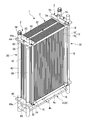
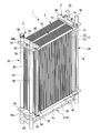
- FIG. 1 is a perspective view showing a first embodiment of the membrane filtration unit of the present invention.
- the membrane filtration unit 1 includes a plurality of flat hollow fiber membrane elements 2; a frame 3 that holds the plurality of hollow fiber membrane elements 2; an air diffuser 4 that is connected to the lower part of the frame 3; A water collecting pipe 5 is provided above and connected to each hollow fiber membrane element 2.
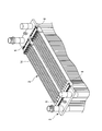
- FIG. 2 is a perspective view showing an example of a hollow fiber membrane element.
- the hollow fiber membrane element 2 includes a hollow fiber membrane sheet 12 in which a plurality of hollow fiber membranes 10 are aligned in one direction; and the upper end of the hollow fiber membrane 10 in the length direction of the hollow fiber membrane sheet 12 is fixed.
- a lower housing 16 in which the lower end of the hollow fiber membrane 10 of the hollow fiber membrane sheet 12 is fixed; and an upper housing disposed on both sides of the hollow fiber membrane sheet 12.
- the upper end of the hollow fiber membrane sheet 12 is inserted into a rectangular tube-shaped upper housing 14 whose both ends are sealed, and the liquid is removed by a potting material (not shown) while the end of the hollow fiber membrane 10 is kept open. It is fixed tightly.
- the lower end of the hollow fiber membrane sheet 12 is inserted into a rectangular tube-shaped lower housing 16 sealed at both ends, and the liquid is removed by a potting material (not shown) while the end of the hollow fiber membrane 10 is kept open. It is fixed tightly.
- the material of the hollow fiber membrane 10 examples include polysulfone resin, polyacrylonitrile, cellulose derivatives, polyolefin (polyethylene, polypropylene, etc.), fluorine resin (polyvinylidene fluoride, polytetrafluoroethylene, etc.), polyamide, polyester, polymethacrylate. , Polyacrylate, those obtained by introducing a substituent into a part of these resins, and resins made of a copolymer of monomers constituting these polymers. Of these, polyvinylidene fluoride is preferable because it is excellent in acid resistance and alkali resistance.
- the hollow fiber membrane 10 preferably contains one or more of these resins.
- the membrane outer diameter of each of the hollow fiber membranes 10 constituting the hollow fiber membrane sheet 12 aligned in one direction is 1 mm or more and 5 mm from the viewpoint of water treatment efficiency, durability of the hollow fiber membrane, and integration rate. Is preferably 1.2 mm or more and 4 mm or less, more preferably 1.3 mm or more and 3 mm or less, and particularly preferably 1.5 mm or more and 2.5 mm or less.
- the material of the upper housing 14 and the lower housing 16 is preferably a material having mechanical strength and durability.
- a material having mechanical strength and durability for example, polycarbonate, polysulfone, polyolefin, polyvinyl chloride, acrylic resin, acrylonitrile-butadiene-styrene (ABS) resin, modified Examples include polyphenylene ether.
- the upper housing 14 and the lower housing 16 preferably contain one or more of these resins.
- potting materials include cured products of thermosetting resins (epoxy resins, unsaturated polyester resins, etc.), polyurethane resins, silicone fillers, and various hot melt resins.
- the vertical rod 18 supports the hollow fiber membrane sheet-like material 12 composed of the hollow fiber membranes 10 aligned in one direction, and avoids the bending of the hollow fiber membrane sheet-like material 12, thereby preventing the hollow fiber membrane element 2 from being bent. A support that maintains its shape. Since the hollow fiber membrane element 2 has the vertical rod 18, the hollow fiber membrane element 2 can be carried and handled easily when the membrane filtration unit 1 is assembled or exchanged, and the hollow fiber membrane element to the frame 3 is improved. 2 and removal of the hollow fiber membrane element 2 from the frame 3 are facilitated.
- Examples of the material of the downpipe 18 include resin (polyvinyl chloride, fluorine-based resin, polyolefin, ABS resin, polycarbonate, etc.) and metal (stainless steel, titanium, etc.).
- the material of the downpipe 18 is preferably a resin from the viewpoint of excellent acid resistance against hydrochloric acid, sulfuric acid, etc., and from the viewpoint of excellent chemical resistance, polyvinyl chloride or fluororesin is more preferable, inexpensive, and other Polyvinyl chloride resin is more preferable from the viewpoint that the adhesiveness with the member is good and the production of the hollow fiber membrane element 2 is easy.
- the “polyvinyl chloride resin” is a resin containing a structural unit derived from vinyl chloride, and is preferably polyvinyl chloride.
- the vertical rod 18 is a round pipe because the hollow fiber membrane 10 is oscillated by aeration from the air diffusing tube 4 and the hollow fiber membrane 10 is less damaged when rubbed against the vertical rod 18 than the square pipe. Is preferred.
- a commercially available polyvinyl chloride pipe is preferable because it is light and inexpensive. Examples of the polyvinyl chloride pipe include a hard polyvinyl chloride pipe (JIS K 6741) and a hard polyvinyl chloride pipe for water supply (JIS K 6742).
- the upper fitting convex portion 20 is fitted into a guide groove 42a of a guide portion 42 in a vertical member 30 of the frame 3 described later, and suppresses lateral displacement of the hollow fiber membrane element 2 in the upper housing 14.
- the lower fitting convex portion 22 is fitted into a guide groove 42a of a guide portion 42 in a vertical member 30 of the frame 3 described later, and suppresses lateral displacement of the hollow fiber membrane element 2 in the lower housing 16.
- the hollow fiber membrane element 2 and the frame 3 are relatively movable in a substantially vertical direction by sliding along the longitudinal direction of the guide groove 42a of the guide portion 42.
- the water intake 24 is for taking out the liquid filtered by the hollow fiber membrane 10 and collected in the water collection space in the upper housing 14 to the outside of the hollow fiber membrane element 2.
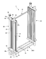
- FIG. 3 is a perspective view showing an example of a frame (excluding a pressing plate).
- the frame 3 includes two vertical members 30 arranged so as to sandwich the hollow fiber membrane element 2 from the longitudinal direction sides of the upper housing 14 and the lower housing 16 and in a substantially vertical direction;
- An upper horizontal member 32 that is disposed between the upper members of the two vertical members 30 and connects the central portions in the horizontal direction; and
- a lower horizontal member 34 that connects the lower members of the vertical members 30 to each other.
- the member 34 also serves as the diffuser tube 4.
- At least a part of the frame 3 also serves as an air supply pipe that supplies gas to the diffuser pipe 4.
- the vertical member 30 includes two support columns 40 arranged in a substantially vertical direction; two guide portions 42 arranged inside the support column 40 so as to sandwich the upper horizontal member 32; and two through pipes 44a.
- An upper support plate 44 having two support columns 40 connected to each other and having the upper ends of the guide portions 42 joined to the side surfaces thereof; two support columns 40 connected to the two through pipes 46a and the guide portions on the side surfaces thereof.
- the holding plate 50 see FIG.
- Support plate 54 An air supply port 56 attached to the upper end of one of the two through tubes 44a; an air supply port 56 attached to the upper end of the through tube 44a to which no air supply port is attached.
- the support column 40 can also serve as an air supply tube for supplying gas to the diffuser tube 4.
- the support column 40 By sealing the upper end of the through pipe 44a of the upper support plate 44 to which the support column 40 not used as the air supply pipe is connected with the cap 58, gas leakage from other than the diffuser pipe 4 can be suppressed.
- the material of the support column 40 examples include resin (polyvinyl chloride, fluorine-based resin, polyolefin, ABS resin, polycarbonate, etc.) and metal (stainless steel, titanium, etc.).
- resin polyvinyl chloride, fluorine-based resin, polyolefin, ABS resin, polycarbonate, etc.
- metal stainless steel, titanium, etc.
- a resin is preferable because it is inexpensive, easy to manufacture the vertical member 30, lightweight, and excellent in chemical resistance, and has good adhesion to other members.
- a polyvinyl chloride resin is more preferable because the vertical member 30 is more easily manufactured.
- the column 40 is preferably a round pipe from the standpoints of mechanical strength and reduction in membrane damage due to the absence of a corner portion of the membrane when the hollow fiber membrane 10 is rubbed against the pipe by peristalsis such as aeration.
- a commercially available polyvinyl chloride pipe is preferable because it is light and inexpensive.
- the polyvinyl chloride pipe include a hard polyvinyl chloride pipe (JIS K 6741) and a hard polyvinyl chloride pipe for water supply (JIS K 6742).
- the guide portion 42 is a corrugated plate member in which a plurality of guide grooves 42 a extending in a substantially vertical direction is formed, and guides the hollow fiber membrane element 2 in a substantially vertical direction.
- the guide groove 42 a suppresses the lateral displacement of the hollow fiber membrane element 2 in the upper housing 14 by fitting the upper fitting convex portion 20 of the upper housing 14.
- the guide groove 42 a is configured to suppress lateral displacement of the hollow fiber membrane element 2 in the lower housing 16 by fitting the lower fitting convex portion 22 of the lower housing 16.
- the lower fitting convex portion 22 slides along the longitudinal direction of the guide groove 42a, thereby enabling the hollow fiber membrane element 2 and the frame 3 to move relatively in the substantially vertical direction.
- the vertical member 30 has the guide portion 42, the vertical member 30 arranged so that the guide portions 42 face each other restricts relative horizontal movement between the hollow fiber membrane element 2 and the frame 3.
- the hollow fiber membrane element 2 can be sandwiched so as to enable relative vertical movement between the hollow fiber membrane element 2 and the frame 3.
- Examples of the material of the guide part 42 include resin (polyvinyl chloride, fluorine-based resin, polyolefin, ABS resin, polycarbonate, etc.) and metal (stainless steel, titanium, etc.).
- the material of the guide portion 42 is preferably a resin because it is inexpensive, easy to manufacture the vertical member 30, lightweight, and excellent in chemical resistance, and has an adhesive property to other members.
- a polyvinyl chloride resin is more preferable because the vertical member 30 is more easily manufactured.
- the upper support plate 44 and the lower support plate 46 are provided with a through pipe for connecting the support column 40.
- irregularities corresponding to the shape of the corrugated guide portion 42 are formed on the side surfaces of the upper support plate 44 and the lower support plate 46 that are joined to the guide portion 42, and the upper support plate 44 and the lower support plate 46.
- the upper support plate 44 and the lower support plate 46 can be sufficiently joined to the guide portion 42 by fitting the recesses and projections of the guide portion 42 to the guide portion 42.
- Examples of the material of the upper support plate 44 and the lower support plate 46 include resin (polyvinyl chloride, fluorine resin, polyolefin, ABS resin, polycarbonate, etc.) and metal (stainless steel, titanium, etc.).
- the material of the upper support plate 44 and the lower support plate 46 is preferably a resin because it is inexpensive, easy to manufacture the vertical member 30, is lightweight, and is excellent in chemical resistance.
- a polyvinyl chloride resin is more preferable from the viewpoint that the adhesiveness with the member is good and the manufacture of the longitudinal member 30 is easier.
- the pressing plate 50 presses the hollow fiber membrane element 2 sandwiched between the vertical members 30 from above.
- the pressing plate 50 suppresses the lifting of the hollow fiber membrane element 2 due to aeration from the air diffusing tube 4 and also suppresses the vibration of the hollow fiber membrane element 2 to reduce wear due to friction between the hollow fiber membrane elements 2. .
- the material of the pressing plate 50 is selected according to the mechanical strength necessary for suppressing the lifting of the hollow fiber membrane element 2.
- the material of the pressing plate 50 is preferably a metal (stainless steel, titanium, etc.) from the viewpoint of high mechanical strength. If there is no problem in mechanical strength, resin or fiber reinforced plastic may be used.
- the pressing plate 50 is preferably fixed to the upper support plate 44 with bolts and nuts. In the adhesion with an epoxy resin or the like, the pressing plate 50 cannot be detachably fixed, and it is difficult to take out the hollow fiber membrane element 2.
- an elastic member (not shown) between the pressing plate 50 and the hollow fiber membrane element 2.
- an elastic member By disposing an elastic member between the pressing plate 50 and the hollow fiber membrane element 2, even if there is a variation in the height of the hollow fiber membrane element 2, the elastic member is deformed so that each hollow fiber membrane element 2 is deformed.
- the hollow fiber membrane element 2 can be reliably pressed in contact therewith. As a result, the vibration of the hollow fiber membrane element 2 is further suppressed.
- the elastic member is made of a thermosetting elastomer (ethylene-propylene-diene rubber (hereinafter also referred to as EPDM), nitrile rubber, fluororubber, silicone rubber, urethane rubber, etc.), thermoplastic elastomer (styrene-based elastomer, olefin-based). Elastomer, vinyl chloride elastomer, ester elastomer, urethane elastomer, amide elastomer, etc.).
- EPDM ethylene-propylene-diene rubber
- nitrile rubber nitrile rubber
- fluororubber silicone rubber
- urethane rubber etc.
- thermoplastic elastomer styrene-based elastomer, olefin-based.
- Elastomer vinyl chloride elastomer, ester elastomer, urethane elastomer, amide elastomer, etc.
- the material of the elastic member is not limited to a thermosetting elastomer and a thermoplastic elastomer, and may be a thermoplastic resin such as polyethylene or polypropylene, or a thermosetting resin such as polyurethane, as long as it is relatively soft. May be.
- the durometer hardness of the elastic member is preferably in the range of A10 to 95. If the durometer hardness of the elastic member is within the above range, the stress generated when the plurality of hollow fiber membrane elements 2 are firmly pressed can be sufficiently relaxed, and the vibration buffering action of the hollow fiber membrane elements 2 can be achieved.
- the durometer hardness of the elastic member is more preferably in the range of A40 to 90. If the durometer hardness of the elastic member is A40 or more, the amount of the elastic member used to obtain sufficient mechanical strength to hold down the hollow fiber membrane element 2 can be suppressed, so that the cost can be suppressed.
- durometer hardness of the elastic member is A90 or less, since the flexibility of the elastic member is increased, the effect of suppressing damage by suppressing the vibration of the hollow fiber membrane element 2 is further increased.
- the durometer hardness of the elastic member is defined by JIS K 6253 (ISO 7619).
- the support plate 54 supports the hollow fiber membrane element 2 sandwiched between the vertical members 30 from below.
- the material of the support plate 54 is selected according to the mechanical strength required to support the mass of the hollow fiber membrane element 2.
- the material of the support plate 54 is preferably a metal (stainless steel, titanium, etc.) from the viewpoint of high mechanical strength. If there is no problem in mechanical strength, resin or fiber reinforced plastic may be used.
- the support plate 54 is preferably fixed to the lower support plate 46 with bolts and nuts. In the case of adhesion using an epoxy resin or the like, there is a risk of peeling on the adhesion surface.
- the air supply header 60 is a member made of an H-shaped pipe. By using the air supply header 60 as a pipe, the air supply header 60 can also serve as an air supply pipe that supplies gas to the diffuser pipe 4.
- the lower ends of the two through pipes 46a of the lower support plate 46 are connected to the two upper ends of the vertical pipes of the air supply header 60, respectively, and the center and the horizontal pipes of the two vertical pipes of the air supply header 60 are connected.
- One end of each of the three diffusing tubes 4 is connected to the center of each.
- Caps (not shown) are attached to the two lower ends of the longitudinal pipes of the air supply header 60.
- Examples of the material of the air supply header 60 include resin (polyvinyl chloride, fluorine-based resin, polyolefin, ABS resin, polycarbonate, etc.) and metal (stainless steel, titanium, etc.).
- resin polyvinyl chloride, fluorine-based resin, polyolefin, ABS resin, polycarbonate, etc.
- metal stainless steel, titanium, etc.
- a resin is preferable because it is inexpensive, easy to manufacture the vertical member 30, is lightweight, and has excellent chemical resistance. Adhesiveness to other members Polyvinyl chloride resin is more preferable because it is easy to manufacture the vertical member 30.
- a blower (not shown) is connected to an air supply port 56 attached to the through pipe 44a of the upper support plate 44 via a hose (not shown).
- a hose (not shown).
- the material of at least some of the members is a resin because it is inexpensive, easy to manufacture the vertical member 30, lightweight, and excellent in chemical resistance. It is preferable that Of the members constituting the vertical member 30, the material of two or more members is preferably a resin from the viewpoint that the adhesiveness between the members is good and the manufacture of the vertical member 30 is easier, and the polyvinyl chloride type More preferably, it is a resin.
- the upper lateral member 32 is an L-shaped member that is disposed so as to be sandwiched between the hollow fiber membrane elements 2 and connects the upper portions of the two longitudinal members 30 and the central portions in the horizontal direction.
- the upper lateral member 32 has its end fixed to the central portion in the horizontal direction of the upper support plate 44 by a bolt (not shown) and an eye nut (hanging bracket 62).
- the material of the upper lateral member 32 is preferably a metal (stainless steel, titanium, etc.) from the viewpoint of high mechanical strength.
- the air diffusing tube 4 is a cylindrical member.
- a plurality of air diffusion holes 4 a opened upward are formed in the peripheral wall of the air diffusion tube 4.
- a sludge discharge pipe 4 b extending downward is provided at the center of the air diffusion pipe 4.
- the diffuser pipe 4 also serves as the lower horizontal member 34 of the frame 3 by connecting both ends thereof to the air supply header 60 below the vertical member 30.
- the water collecting pipe 5 includes a plurality of connecting pipes 5a extending in the vertical direction connected to the water intake ports 24 of the hollow fiber membrane elements 2, a collecting pipe 5b extending in the horizontal direction connected to the plurality of connecting pipes 5a, and a collecting pipe 5b.
- a water intake pipe 5c extending upward from the center.
- connection pipe 5a of the water collection pipe 5 is connected to the water intake 24 of each hollow fiber membrane element 2, and the water intake pipe 5c of the water collection pipe 5 is connected to a suction pump (not shown) via a hose (not shown).
- a suction pump not shown
- the suction pump By operating the suction pump, the liquid filtered by the hollow fiber membrane 10 and collected in the water collection space in the upper housing 14 is taken out from the hollow fiber membrane element 2 to the water collection pipe 5 and assembled, and then the water collection pipe 5 to the outside of the membrane filtration unit 1.
- the plurality of hollow fiber membrane elements 2 are such that the hollow fiber membrane sheet-like material 12 faces each other, the longitudinal directions of the upper housing 14 and the lower housing 16 are aligned, and between and adjacent to the adjacent upper housings 14. It arrange
- interval X is the space
- the interval X is preferably 3 to 25 mm, and more preferably 5 to 15 mm. If the interval X is equal to or greater than the lower limit of the above range, a gas-liquid mixed flow due to aeration easily flows between the hollow fiber membranes 10, so that sludge is not blocked between the membranes and a more stable operation is possible. If the space
- the two vertical members 30 of the frame 3 are arranged so as to sandwich the hollow fiber membrane element 2 from the longitudinal direction side of the upper housing 14 and the lower housing 16.
- the upper transverse member 32 of the frame 3 is disposed so as to be sandwiched between the hollow fiber membrane elements 2.
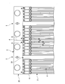
- the side surface A of the short portion of the upper support plate 44 of the vertical member 30, that is, the side surface A of the upper support plate 44 in the width direction orthogonal to the longitudinal direction of the upper housing 14 and the lower housing 16 is the outermost side. 4 is the same as the outermost surface B ′ of the outer surfaces B (ie, the upper housing 14 and the lower housing 16) of the hollow fiber membrane element 2 disposed in the same plane, that is, in the same plane, or FIG. It is preferable that the side surface A protrudes so that the maximum step Y between the side surface A and the surface B is equal to or less than 0 distance X as shown in FIG.
- the hollow fiber membrane element 2 is disposed in the frame 3 without waste, and the membrane filtration unit 1 can be further compacted. If the side surface A protrudes so that the maximum step Y between the side surface A and the surface B is less than 0 distance X or less, the outermost hollow fiber membrane elements 2 face each other as shown in FIG. When the membrane filtration units 1 are arranged side by side and the side surfaces A are brought into contact with each other, a gap is formed between the surfaces B of the hollow fiber membrane elements 2 arranged on the outermost side in each membrane filtration unit 1, and The interval between the hollow fiber membrane elements 2 does not become too large.
- the maximum level difference Y between the side surface A and the surface B is such that the distance between the hollow fiber membrane elements 2 arranged on the outermost side in each membrane filtration unit 1 is the distance X between the hollow fiber membrane elements 2 in the membrane filtration unit 1. From the point of being the same, it is preferable that it is half of the interval X.
- the membrane filtration unit 1, film packing density determined from the following formula (I) is preferably from 150 ⁇ 350m 2 / m 2, more preferably 200 ⁇ 300m 2 / m 2.
- D is the membrane packing density
- n is the number of hollow fiber membrane elements 2 arranged in the membrane filtration unit 1
- E i is the total surface area of the hollow fiber membranes 10 in the i-th hollow fiber membrane element 2.
- U is an area required for installing the membrane filtration unit 1.
- the membrane filtration unit 1 can be made more compact. If the membrane packing density of the membrane filtration unit 1 is less than or equal to the upper limit of the above range, an appropriate gap is formed between the hollow fiber membranes 10 and a gas-liquid mixed flow due to aeration easily flows, so that sludge is not blocked between the membranes. This enables stable operation.
- the lower fitting convex portion 22 of the lower housing 16 in the hollow fiber membrane element 2 is formed in the guide groove 42 a of the guide portion 42 in the vertical member 30 of the frame 3 (however, excluding the pressing plate 50). Fit.
- the hollow fiber membrane element 2 is inserted into the frame 3 while being guided downward by sliding the lower fitting convex portion 22 along the longitudinal direction of the guide groove 42a.
- the upper fitting convex portion 20 of the upper housing 14 in the hollow fiber membrane element 2 is fitted into the guide groove 42a. In this way, the hollow fiber membrane element 2 is sandwiched by the two longitudinal members 30 from the longitudinal direction sides of the upper housing 14 and the lower housing 16. The same operation is repeated for the number of hollow fiber membrane elements 2.
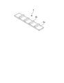
- an elastic member 6 shown in FIG. 7 is prepared.
- the elastic member 6 has an elongated flat plate-like base material portion 6a; the same width as the gap between the hollow fiber membrane elements 2, and the same pitch as the pitch of the hollow fiber membrane elements 2 arranged in the frame 3. And a plurality of convex portions 6b formed.
- the four elastic members 6 are arranged in the upper housing 14 of the hollow fiber membrane element 2 arranged in the frame 3 so that the convex portion 6 b is fitted in the gap between the hollow fiber membrane elements 2. Attach to both ends in the longitudinal direction.
- the hollow fiber membrane element 2 is inserted through the elastic member 6 by inserting bolts 48 into the bolt holes of the pressing plate 50 and the upper support plate 44 and attaching nuts (not shown) to the bolts 48.
- the pressing plate 50 is fixed to the upper support plate 44 in the vertical member 30 of the frame 3 so as to be pressed from above.
- the water intake ports 24 of the hollow fiber membrane elements 2 aligned in a line are connected to the connection pipe 5 a of the water collecting pipe 5.
- the water collecting pipe 5 is attached above the hollow fiber membrane element 2.
- the membrane filtration unit 1 in which the plurality of hollow fiber membrane elements 2 are held by the frame 3 is obtained.
- the air diffuser 4 is connected to the lower part of the frame 3 holding the plurality of hollow fiber membrane elements 2. That is, it is set as the structure where the hollow fiber membrane module and the air diffuser which were produced separately in the conventional membrane filtration unit were integrated. Therefore, unlike the conventional case, there is no need to connect the frame of the hollow fiber membrane module and the frame of the air diffuser with bolts and nuts, and for providing a connecting portion for passing the bolt through each frame for connecting the frames. There is no need for extra space, and there is no need for processing for drilling bolt holes in the connecting portion, and no work for connecting the frames. For this reason, it is possible to realize downsizing and cost reduction as compared with the conventional membrane filtration unit.
- the support column 40 and the air supply header 60 which are a part of the frame 3 also serve as an air supply pipe for supplying gas to the air diffusing pipe 4.
- the space required for installing the membrane filtration unit can be reduced by the amount of the supply pipe, and the number of parts can be reduced. Therefore, further downsizing and cost reduction can be realized as compared with the conventional membrane filtration unit.
- the air diffuser 4 also serves as the lower horizontal member 34 that is a part of the frame 3, so that it is not necessary to separately provide a horizontal member at the lower portion of the frame 3. . Therefore, further downsizing and cost reduction can be realized as compared with the conventional membrane filtration unit.
- the frame 3 includes two vertical members 30 arranged so as to sandwich the hollow fiber membrane element 2 and extending in a substantially vertical direction, and the vertical member 30 is a hollow fiber. Since it has the guide part 42 which guides the membrane element 2 in a substantially vertical direction, the hollow fiber membrane element 2 is detachably arranged in the frame 3. That is, the hollow fiber membrane element 2 can be drawn upward from the membrane filtration unit 1 and the hollow fiber membrane element 2 can be inserted into the membrane filtration unit 1 from above.
- the hollow fiber membrane element 2 can be taken out from the membrane filtration unit 1 without taking the membrane filtration unit 1 out of the reaction tank, in a site where it is difficult to pull up the membrane filtration unit 1 with a water supply facility in a building, etc. Work such as maintenance can be easily performed.
- the membrane filtration unit 1 described above preferably has an overall height of 1 m or more and 1.5 m or less. If the total height of the membrane filtration unit 1 is equal to or greater than the lower limit of the range, the membrane area per module volume can be maintained, and if the total height is equal to or less than the upper limit of the range, the unit is put into a treatment facility with a ceiling restriction Becomes easy.
- the weight per membrane surface area of the membrane filtration unit 1 is 0.00. It is preferably 4 kg / m 2 or more and 1.0 kg / m 2 or less, and more preferably 0.5 kg / m 2 or more and 0.7 kg / m 2 or less.
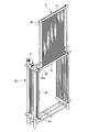
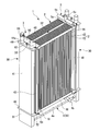
- FIG. 11 is a perspective view showing a second embodiment of the membrane filtration unit of the present invention.
- the membrane filtration unit 1 of the second embodiment is an example in which gas is supplied from one of the two vertical members 30 of the frame 3 to the diffuser tube 4.
- the change from the first embodiment is that the air supply port 56 is attached to one of the through pipes 44a of the upper support plate 44 of one of the two vertical members 30, and the other through pipes 44a are all capped.
- 58 is a point; a sludge discharge pipe 4b is provided at the end of the air diffuser 4 opposite to the side to which the gas is supplied.
- FIG. 12 is a perspective view showing a third embodiment of the membrane filtration unit of the present invention.
- the same components as those in the first embodiment or the second embodiment are denoted by the same reference numerals, and detailed description thereof is omitted.
- the membrane filtration unit 1 according to the third embodiment is an example in which a column that also serves as an air supply pipe in the vertical member 30 of the frame 3 is formed in a rectangular tube shape.
- the change from the second embodiment is that two struts 40 made of round pipes in the vertical member 30 of the frame 3 are changed to one square column-shaped strut 41;
- the H-shaped air supply header 60 is changed to a rectangular tube-shaped air supply header 61.
- the support column 41 and the air supply header 61 are connected via a through pipe (not shown) formed in the lower support plate 46.
- the membrane filtration unit of the present invention includes a plurality of membrane elements, a frame holding the plurality of membrane elements, and an air diffuser connected to a lower portion of the frame, and at least a part of the frame supplies gas to the air diffuser. What is necessary is just to also serve as an air supply pipe
- the membrane element is preferably a hollow fiber membrane element having a high packing density, but may be a flat membrane element.
- the vertical rod in the membrane element is not limited to a round pipe, and may be a square pipe as long as there is no problem of mechanical strength and membrane damage due to rubbing with the pipe.
- the cross-sectional shape of the square pipe is not limited to a quadrangle, and may be another shape such as a hexagon.
- the fitting convex portion in the membrane element for guiding the membrane element in the substantially vertical direction may be a guide groove. In this case, the guide groove in the guide portion of the vertical member of the counterpart frame is a fitting convex portion.
- the struts in the vertical members of the frame are not limited to round pipes, but may be square pipes as long as there are no problems such as mechanical strength and damage caused by rubbing when the hollow fiber membrane comes into contact.
- the cross-sectional shape of the square pipe is not limited to a quadrangle, and may be another shape such as a hexagon.
- those that do not serve as the air supply pipes may be solid cylindrical. In this case, it is not necessary to attach a cap to the through pipe 44a to which the columnar column is connected.
- the number of columns in the vertical member of the frame may be one or more per vertical member, and may be set as appropriate according to the size of the membrane filtration unit. As shown in FIG. 1, the number of pillars in the vertical member of the frame is a frame-like structure when connected to the upper support plate and the lower support plate, and the vertical member is stable without wobbling. Two per member are preferred.
- the guide portion in the vertical member of the frame may be divided vertically so as to divide the guide groove in the middle. However, if the guide part is divided vertically, positioning with respect to the lower guide part becomes difficult when the membrane element is inserted.
- the upper support plate and the lower support plate in the vertical member of the frame may have the same shape or different shapes. Since only one mold for forming a molded product is required, the upper support plate and the lower support plate preferably have the same shape from the viewpoint that no extra cost is generated.
- the presser plate and the support plate in the vertical member of the frame may be integrated with the upper support plate and the lower support plate, respectively, as long as there is no problem in mechanical strength.
- the fastening means for fastening each member is not limited to bolts and nuts, and may be other means (for example, a giant clam vise).
- the number of water collecting pipes is not limited to one. For example, when the membrane element is long in the substantially vertical direction, the transmembrane differential pressure increases only with the upper water collecting pipe. Another water collecting pipe may be connected to the lower housing in order to reduce the transmembrane pressure difference in the longitudinal direction of the membrane.
- the water treatment method of the present invention includes solid-liquid separation using the membrane filtration unit of the present invention.
- a known aspect can be adopted except that the membrane filtration unit of the present invention is used.
- various wastewaters industrial wastewater, domestic wastewater, etc.
- bacteria, etc. microorganisms
- their debris are biochemically treated with activated sludge in the activated sludge water tank, and in the activated sludge water tank
- Water treatment can be performed by solid-liquid separation of sludge and treated water by the immersed membrane filtration unit of the present invention.
- the activated sludge water tank may have a water depth of 1.5 m or less.
- Example 1 The membrane filtration unit 1 of FIG. 11 was produced as follows.
- the air diffuser 4 was made by opening seven air diffuser holes 4a in a hard polyvinyl chloride tube (VP13, outer diameter 18 mm, inner diameter 13 mm).
- An H-shaped air supply header 60 made of a rigid polyvinyl chloride pipe having three holes for connecting the air diffusion pipe 4 is attached to each end of the three air diffusion pipes 4 with an adhesive for polyvinyl chloride. Glued and fixed.
- a lower support plate 46 provided with two through pipes 46a made of rigid polyvinyl chloride pipes (VP30, outer diameter 38 mm, inner diameter 31 mm) is prepared, and penetrates through the two upper ends of the vertical pipes of the air supply header 60
- the tube 46a was fixed with an adhesive for polyvinyl chloride.
- Caps (not shown) were bonded and fixed to the two lower ends of the longitudinal pipes of the air supply header 60 with an adhesive for polyvinyl chloride.
- a support plate 54 made of stainless steel (SUS304) having an L-shaped cross section was fixed to the lower support plate 46 with a hexagon socket bolt and a nut 52.
- a strut 40 made of a hard polyvinyl chloride pipe (VP30, outer diameter 38 mm, inner diameter 31 mm) was fixed to each of the two through pipes 46a of the lower support plate 46 with an adhesive for polyvinyl chloride.
- the end portions of the upper cross member 32 made of stainless steel (SUS304) having an L-shaped cross section were fastened and fixed to each of the two upper support plates 44 with hexagon socket bolts and eye nuts (suspending fittings 62). Thereby, the upper part of the membrane filtration unit 1 was reinforced, and the membrane filtration unit 1 could be suspended and pulled up from the reaction vessel.
- the lower end of the guide portion 42 was bonded to the side surface of the lower support plate 46, and the upper end of the guide portion 42 was bonded to the side surface of the upper support plate 44. In this way, a total of four guide portions 42 were attached.
- a socket serving as an air supply port 56 was adhered and fixed to the upper end of one of the four through pipes 44a with an adhesive for polyvinyl chloride.
- the air supply port 56 and the air diffuser 4 communicate with each other.
- Caps 58 were adhered and fixed to the upper ends of the other three through pipes 44a with an adhesive for polyvinyl chloride.
- the air supplied from the air supply port 56 is structured not to leak from the portion other than the air diffuser 4.
- the lower fitting convex portion 22 of the hollow fiber membrane element 2 (membrane area: 5 m 2 ) shown in FIG. 2 is fitted into the guide groove 42a of the guide portion 42 and slid downward as shown in FIG. Then, the hollow fiber membrane element 2 was inserted into the frame. A total of ten hollow fiber membrane elements 2 were inserted into the frame 3. The thickness of the hollow fiber membrane element 2 in the vicinity of the center of the housing was 13 mm, and these were arranged at a pitch of 23 mm. Therefore, the interval X between the hollow fiber membrane elements 2 in the vicinity of the center of the housing was 10 mm.
- the elastic member 6 made of EPDM shown in FIG. 7 (the thickness of the base material portion 6a not including the convex portion 6b: 6 mm, durometer hardness: A70) is set to the gap between the hollow fiber membrane elements 2 as shown in FIG.
- the hollow fiber membrane elements 2 arranged in the frame 3 were attached to both ends in the longitudinal direction of the upper housing 14 so that the convex portions 6b were fitted to each other.
- hexagon socket head bolts 48 are inserted into the bolt holes of the stainless steel (SUS304) pressing plate 50 and the upper support plate 44, and nuts (not shown) are attached to the bolts 48. These were tightened until they contacted all the hollow fiber membrane elements 2 without any gaps. In this way, the pressing plate 50 was fixed to the upper support plate 44 so as to press the hollow fiber membrane element 2 from above via the elastic member 6.
- the water collecting pipe 5 was attached above the hollow fiber membrane element 2 by connecting the water intake port 24 of the hollow fiber membrane element 2 and the connecting pipe 5 a of the water collecting pipe 5. As described above, a membrane filtration unit 1 in which a plurality of hollow fiber membrane elements 2 were held by a frame 3 was obtained.
- the outer dimensions of the membrane filtration unit 1 were width: 825 mm, depth: 260 mm, and height: 1296 mm.
- the maximum step Y between the side surface A and the surface B in FIG. 4 was 5 mm. Therefore, when the plurality of membrane filtration units 1 are arranged side by side without any gap, the interval between the hollow fiber membrane elements 2 arranged on the outermost side in each membrane filtration unit 1 is the hollow fiber membrane element 2 in the membrane filtration unit 1.
- the interval X between them could be the same as 10 mm.
- the gap between the hollow fiber membrane elements 2 can be 10 mm in all parts other than the part to which the upper transverse member is fixed, thereby reducing the membrane packing density. It was confirmed that the hollow fiber membrane elements 2 could be arranged without any problem.
- the membrane filtration unit 1 is immersed in a reaction tank that performs biochemical treatment by the membrane-separated activated sludge method, a hose is connected to the water collection pipe 5, and the raw water is filtered by suction at 1.25 m 3 / h by a suction pump.
- a hose is connected to the air supply port 56 and blown with a blower at 13.4 Nm 3 / h for aeration, the operation is continued for one month, and the suction differential pressure of the membrane filtration is stable without increasing. I was able to drive. From the above results, it was confirmed that the membrane filtration unit 1 that is compact and capable of stable operation can be obtained at low cost by using a part of the frame 3 constituting the membrane filtration unit 1 as an air supply pipe.
- the membrane filtration unit of the present invention is used for the treatment of highly polluted water (secondary or tertiary treatment in a sewage treatment plant, solid-liquid separation in a septic tank, solid-liquid separation of SS (suspended material) in industrial wastewater, etc.), It is suitably used for aseptic water, drinking water, high-purity pure water production applications, air purification applications, and the like.
- 1 membrane filtration unit 2 hollow fiber membrane element, 3 frame, 4 air diffuser tube, 4a air diffuser hole, 4b sludge discharge tube, 5 water collecting tube, 5a connecting tube, 5b collecting tube, 5c water intake tube, 6 elastic member, 6a base Material part, 6b convex part, 10 hollow fiber membrane, 12 hollow fiber membrane sheet, 14 upper housing, 16 lower housing, 18 vertical shaft, 20 upper fitting convex part, 22 lower fitting convex part, 24 water intake, 30 vertical members, 32 upper horizontal members, 34 lower horizontal members, 40 struts, 41 struts, 42 guide sections, 42a guide grooves, 44 upper support plates, 44a through pipes, 46 lower support plates, 46a through pipes, 48 bolts, 50 Presser plate, 52 nut, 54 support plate, 56 air supply port, 58 cap, 60 air supply header, 61 air supply header, 62 hanging bracket, A Aspect, B surfaces, B 'surface, X interval, Y maximum step.
Landscapes
- Chemical & Material Sciences (AREA)
- Chemical Kinetics & Catalysis (AREA)
- Life Sciences & Earth Sciences (AREA)
- Hydrology & Water Resources (AREA)
- Engineering & Computer Science (AREA)
- Environmental & Geological Engineering (AREA)
- Water Supply & Treatment (AREA)
- Organic Chemistry (AREA)
- Biodiversity & Conservation Biology (AREA)
- Microbiology (AREA)
- Separation Using Semi-Permeable Membranes (AREA)
Abstract
Description
本願は、2015年11月10日に日本に出願された特願2015-220574号に基づき優先権を主張し、その内容をここに援用する。
また、従来の膜ろ過ユニットでは、散気装置の散気管に気体を供給するための給気管を別途設ける必要がある。給気管は、各フレームの外側に配設され、中空糸膜モジュールのフレーム等にUボルト等で固定される。そのため、給気管を含めた膜ろ過ユニットの設置に必要な空間がさらに大きくなる。また、部品が増えることによって、製造コストがさらに高くなる。
[1]複数の膜エレメントと、
前記複数の膜エレメントを保持するフレームと、
前記フレームの下部に接続する散気管とを備え、
前記フレームの少なくとも一部が、前記散気管に気体を供給する給気管を兼ねている、膜ろ過ユニット。
[2]前記フレームが、前記膜エレメントを挟持する、略鉛直方向に配置された2つの縦部材を備え、
前記縦部材の少なくとも一部が、前記散気管に気体を供給する給気管を兼ねている、[1]に記載の膜ろ過ユニット。
[3]前記フレームが、前記膜エレメントを挟持する、略鉛直方向に配置された2つの縦部材を備え、
前記縦部材が、前記膜エレメントを略鉛直方向に案内するガイド部を有する、[1]または[2]に記載の膜ろ過ユニット。
[4]下記式(I)から求めた膜充填密度が、150~350m2/m2である、[1]~[3]のいずれか一項に記載の膜ろ過ユニット。

ただし、Dは膜充填密度であり、nは膜ろ過ユニットに配置された膜エレメントの数であり、Eiはi番目の膜エレメントにおける膜の表面積であり、Uは膜ろ過ユニットの設置に必要な面積である。
[5]前記フレームが、前記膜エレメントを挟持する、略鉛直方向に配置された2つの縦部材を備え、
前記縦部材の少なくとも一部の材質が、樹脂である、[1]~[4]のいずれか一項に記載の膜ろ過ユニット。
[6]前記樹脂が、ポリ塩化ビニル系樹脂である、[5]に記載の膜ろ過ユニット。
[7]前記フレームが、前記膜エレメントを挟持する、略鉛直方向に配置された2つの縦部材と、前記2つの縦部材と接続する横部材とを備え、
前記散気管が、前記横部材の少なくとも一部を兼ねている、[1]~[6]のいずれか一項に記載の膜ろ過ユニット。
[8]前記膜エレメントが、シート状の膜と、前記膜の上端が固定された上部ハウジングと、前記膜の下端が固定された下部ハウジングとを備え、
前記複数の膜エレメントが、前記膜が互いに対面し、前記上部ハウジングおよび前記下部ハウジングの長手方向が揃い、かつ隣り合う前記上部ハウジング間および隣り合う前記下部ハウジング間が所定間隔Xをあけるように配置され、
前記フレームが、前記上部ハウジングおよび前記下部ハウジングの長手方向側から前記膜エレメントを挟持する、略鉛直方向に配置された2つの縦部材を備え、
前記縦部材が、上部支持板を備え、前記上部ハウジングおよび前記下部ハウジングの長手方向に直交する幅方向の、前記上部支持板の側面Aが、最も外側に配置された膜エレメントの外側の表面Bのうち最も外側の表面B’と同一平面上にあるか、または、前記側面Aが、前記側面Aと前記表面Bとの最大段差Yが0超前記間隔X以下となるように突出している、[1]~[7]のいずれか一項に記載の膜ろ過ユニット。
[9]前記膜エレメントが、シート状の膜を備え、前記シート状の膜の膜外径が、1mm以上5mm以下であることを特徴とする、[1]~[8]のいずれか一項に記載の膜ろ過ユニット。
[10]前記膜エレメントが、シート状の膜を備え、前記膜エレメントは支持体を有する、[1]~[9]のいずれか一項に記載の膜ろ過ユニット。
[11]全高が1m以上1.5m以下である、[1]~[10]のいずれか一項に記載の膜ろ過ユニット。
[12]膜表面積当たりの重量が1.0kg/m2以下である、[1]~[11]のいずれか一項に記載の膜ろ過ユニット。
[13][1]~[12]のいずれか一項に記載の膜ろ過ユニットを用いて固液分離することを含む水処理方法。
[14][1]~[12]のいずれか一項に記載の膜ろ過ユニットを活性汚泥水槽内で用いる、[13]に記載の水処理方法。
[15][11]に記載の膜ろ過ユニットを、水深が1.5m以下の活性汚泥水槽内で用いる、[13]に記載の水処理方法。
<第1の実施形態>
図1は、本発明の膜ろ過ユニットの第1の実施形態を示す斜視図である。
膜ろ過ユニット1は、複数の平型の中空糸膜エレメント2と;複数の中空糸膜エレメント2を保持するフレーム3と;フレーム3の下部に接続する散気管4と;中空糸膜エレメント2の上方に配置され、各中空糸膜エレメント2と接続する集水管5とを備える。
図2は、中空糸膜エレメントの一例を示す斜視図である。
中空糸膜エレメント2は、複数の中空糸膜10が一方向に引き揃えられた中空糸膜シート状物12と;中空糸膜シート状物12の中空糸膜10の長さ方向の上端が固定された上部ハウジング14と;中空糸膜シート状物12の中空糸膜10の長さ方向の下端が固定された下部ハウジング16と;中空糸膜シート状物12の両脇に配置され、上部ハウジング14の端部と下部ハウジング16の端部とを接続する2本の縦杆18と;上部ハウジング14の端部から上部ハウジング14の長手方向の外方に突出して形成された上部嵌合凸部20と;下部ハウジング16の端部から下部ハウジング16の長手方向の外方に突出して形成された下部嵌合凸部22と;上部ハウジング14の一方の端部から上方に突出して形成された取水口24とを備える。
中空糸膜シート状物12の下端は、両端が封止された角筒状の下部ハウジング16に挿入され、中空糸膜10の端部の開口を保った状態でポッティング材(図示略)によって液密に固定されている。
中空糸膜10は、これらの樹脂のうちの1種以上を含むことが好ましい。
丸パイプとしては、軽く、かつ安価である点から、市販のポリ塩化ビニル管が好ましい。ポリ塩化ビニル管としては、硬質ポリ塩化ビニル管(JIS K 6741)、水道用硬質ポリ塩化ビニル管(JIS K 6742)等が挙げられる。
図3は、フレーム(ただし、押さえ板を除く。)の一例を示す斜視図である。
フレーム3は、上部ハウジング14および下部ハウジング16の長手方向側から中空糸膜エレメント2を挟持するように、かつ、略鉛直方向に配置された2つの縦部材30と;中空糸膜エレメント2の間に挟まれるように配置され、2つの縦部材30の上部かつ水平方向の中央部同士を接続する上部横部材32と;縦部材30の下部同士を接続する下部横部材34とを備え、下部横部材34は散気管4を兼ねている。
フレーム3の少なくとも一部は、散気管4に気体を供給する給気管を兼ねる。
縦部材30は、略鉛直方向に配置された2本の支柱40と;支柱40よりも内側で、上部横部材32を挟むように配置された2枚のガイド部42と;2つの貫通管44aに2本の支柱40がそれぞれ接続され、かつ側面にガイド部42の上端が接合された上部支持板44と;2つの貫通管46aに2本の支柱40がそれぞれ接続され、かつ側面にガイド部42の下端が接合された下部支持板46と;縦部材30間に挟持された中空糸膜エレメント2を上方から押さえつけるように上部支持板44にボルト48(図1参照)およびナット(図示略)で固定された押さえ板50(図1参照)と;縦部材30間に挟持された中空糸膜エレメント2を下方から支えるように下部支持板46にボルト(図示略)およびナット52で固定された支え板54と;2つの貫通管44aのうちの1つの貫通管44aの上端に取り付けられた給気口56と;2つの貫通管44aのうち、給気口が取り付けられなかった貫通管44aの上端に取り付けられたキャップ58と;2つの貫通管46aの下端および3本の散気管4の一方の端部に接続する給気ヘッダ60と;上部支持板44に取り付けられた吊金具62とを備える。
給気管として用いていない支柱40が接続された上部支持板44の貫通管44aの上端をキャップ58で封止することによって、散気管4以外からの気体の漏れが抑えられる。
丸パイプとしては、軽く、かつ安価である点から、市販のポリ塩化ビニル管が好ましい。ポリ塩化ビニル管としては、硬質ポリ塩化ビニル管(JIS K 6741)、水道用硬質ポリ塩化ビニル管(JIS K 6742)等が挙げられる。
ガイド溝42aは、上部ハウジング14の上部嵌合凸部20が嵌合することによって、上部ハウジング14における中空糸膜エレメント2の横ずれを抑制するものである。
ガイド溝42aは、下部ハウジング16の下部嵌合凸部22が嵌合することによって、下部ハウジング16における中空糸膜エレメント2の横ずれを抑制するものである。また、ガイド溝42aの長手方向に沿って下部嵌合凸部22が摺動することによって、中空糸膜エレメント2とフレーム3とを相対的に略鉛直方向に移動可能にするものである。
押さえ板50は、散気管4からの曝気等による中空糸膜エレメント2の浮き上がりを抑えるとともに、中空糸膜エレメント2の振動を抑えて中空糸膜エレメント2同士の擦れによる摩耗を低減するものである。
上部支持板44への押さえ板50の固定は、ボルトとナットによって行うことが好ましい。エポキシ樹脂等による接着では、押さえ板50を着脱可能に固定できず、中空糸膜エレメント2の取り出しが困難となる。
弾性部材のデュロメータ硬さは、JIS K 6253(ISO 7619)で規定される。
支え板54の材質は、中空糸膜エレメント2の質量を支えるために必要な機械的強度に応じて選択される。支え板54の材質としては、機械的強度が高い点から、金属(ステンレス、チタン等)が好ましい。機械的強度に問題がなければ、樹脂または繊維強化プラスチックを用いてもよい。
下部支持板46への支え板54の固定は、ボルトとナットによって行うことが好ましい。エポキシ樹脂等による接着では、接着面で剥離するおそれがある。
給気ヘッダ60をパイプとすることによって、給気ヘッダ60が散気管4に気体を供給する給気管を兼ねることができる。
給気ヘッダ60の縦方向のパイプの2つの上端に下部支持板46の2つの貫通管46aの下端がそれぞれ接続され、給気ヘッダ60の縦方向の2本のパイプの中央および横方向のパイプの中央に3本の散気管4の一方の端部がそれぞれ接続される。給気ヘッダ60の縦方向のパイプの2つの下端にはキャップ(図示略)が取り付けられる。
ブロワ、ホース、給気口56、貫通管44a、支柱40、貫通管46a、給気ヘッダ60、散気管4の順に連通させることによって、フレーム3の一部である支柱40を給気管として併用させながら、ブロワから散気管4へ気体を供給できる。
上部横部材32は、中空糸膜エレメント2の間に挟まれるように配置され、2つの縦部材30の上部かつ水平方向の中央部同士を接続する断面L字型の部材である。
上部横部材32は、ボルト(図示略)とアイナット(吊金具62)によってその端部が上部支持板44の水平方向の中央部に固定される。
上部横部材32の材質としては、機械的強度が高い点から、金属(ステンレス、チタン等)が好ましい。
散気管4は、円筒状の部材である。
散気管4の周壁には、上方に開口した複数の散気穴4aが形成されている。
散気管4の中央部には、下方に向かって延びる汚泥排出管4bが設けられている。
散気管4は、その両端がそれぞれ縦部材30の下部の給気ヘッダ60に接続することによって、フレーム3の下部横部材34を兼ねている。
集水管5は、各中空糸膜エレメント2の取水口24と接続する上下方向に延びる複数の接続管5aと;複数の接続管5aと接続する水平方向に延びる集合管5bと;集合管5bの中央から上方に延びる取水管5cとを有する。
吸引ポンプを作動させることによって、中空糸膜10でろ過され、上部ハウジング14内の集水空間に集められた液体を、中空糸膜エレメント2から集水管5に取り出し、集合させた後、集水管5から膜ろ過ユニット1の外部に取り出す。
図4に示すように、複数の中空糸膜エレメント2は、中空糸膜シート状物12が互いに対面し、上部ハウジング14および下部ハウジング16の長手方向が揃い、かつ隣り合う上部ハウジング14間および隣り合う下部ハウジング16間が所定間隔Xをあけるように配置される。
間隔Xは、3~25mmが好ましく、5~15mmがより好ましい。間隔Xが前記範囲の下限値以上であれば、中空糸膜10間に曝気による気液混合流が流れ込みやすいため、膜間に汚泥が閉塞せずにより安定した運転が可能となる。間隔Xが前記範囲の上限値以下であれば、膜ろ過ユニット1をさらにコンパクト化できる。
フレーム3の上部横部材32は、中空糸膜エレメント2の間に挟まれるように配置される。
フレーム3の縦部材30および上部横部材32が上述したように配置されることによって、複数の中空糸膜エレメント2のうち、最も外側に配置された中空糸膜エレメント2の中空糸膜シート状物12の膜面が、膜ろ過ユニット1の外側に露出するようになる。
側面Aが、側面Aと表面Bとの最大段差Yが0超間隔X以下となるように突出していれば、図5に示すように、最も外側に配置された中空糸膜エレメント2が互いに対面するように膜ろ過ユニット1を並設し、側面A同士を当接した際に、各膜ろ過ユニット1において最も外側に配置された中空糸膜エレメント2の表面B間に空隙が形成され、かつ中空糸膜エレメント2間の間隔が大きくなりすぎない。側面Aと表面Bとの最大段差Yは、各膜ろ過ユニット1において最も外側に配置された中空糸膜エレメント2間の間隔が、膜ろ過ユニット1内の中空糸膜エレメント2間の間隔Xと同じになる点から、間隔Xの半分であることが好ましい。
膜ろ過ユニット1の、下記式(I)から求めた膜充填密度は、150~350m2/m2が好ましく、200~300m2/m2がより好ましい。

膜ろ過ユニット1の組み立てについて図面を参照しながら説明する。
ガイド溝42aの長手方向に沿って下部嵌合凸部22を摺動させることによって、中空糸膜エレメント2を下方に案内しながらフレーム3内に挿入する。
下部ハウジング16を支え板54に当接させると同時に、ガイド溝42aに、中空糸膜エレメント2における上部ハウジング14の上部嵌合凸部20を嵌合させる。
このようにして、2つの縦部材30によって、上部ハウジング14および下部ハウジング16の長手方向側から中空糸膜エレメント2を挟持する。
同じ操作を中空糸膜エレメント2の数だけ繰り返す。
図8に示すように、4つの弾性部材6を、中空糸膜エレメント2間の間隙に凸部6bが嵌合するように、フレーム3内に配列された中空糸膜エレメント2の上部ハウジング14の長手方向の両端部に取り付ける。
以上のようにして、複数の中空糸膜エレメント2がフレーム3によって保持された膜ろ過ユニット1を得る。
以上説明した膜ろ過ユニット1にあっては、複数の中空糸膜エレメント2を保持しているフレーム3の下部に散気管4を接続している。すなわち、従来の膜ろ過ユニットでは別々に作製されていた中空糸膜モジュールと散気装置とが一体化された構造とされている。そのため、従来のように、中空糸膜モジュールのフレームと散気装置のフレームとをボルトとナットによって連結する必要がなく、フレーム同士の連結のために各フレームにボルトを通す連結部分を設けるための余分なスペースも必要なく、連結部分にボルト用穴を穿設するための加工の手間、およびフレーム同士を連結するための作業の手間も必要ない。そのため、従来の膜ろ過ユニットに比べてコンパクト化および低コスト化を実現できる。
図11は、本発明の膜ろ過ユニットの第2の実施形態を示す斜視図である。第1の実施形態と同じ構成のものについては、同じ符号を付して詳しい説明を省略する。
第2の実施形態の膜ろ過ユニット1は、フレーム3の2つの縦部材30のうちの一方から散気管4に気体を供給するようにした例である。
第1の実施形態からの変更点は、給気口56を、2つの縦部材30のうちの一方の上部支持板44の貫通管44aの1つに取り付け、他の貫通管44aのすべてにキャップ58を取り付けた点;散気管4の気体が供給される側とは反対側の端部に、汚泥排出管4bを設けた点である。
図12は、本発明の膜ろ過ユニットの第3の実施形態を示す斜視図である。第1の実施形態または第2の実施形態と同じ構成のものについては、同じ符号を付して詳しい説明を省略する。
第3の実施形態の膜ろ過ユニット1は、フレーム3の縦部材30において給気管を兼ねている支柱を角筒状にした例である。
第2の実施形態からの変更点は、フレーム3の縦部材30における丸パイプからなる2本の支柱40を、1本の角筒状の支柱41に変更した点;フレーム3の縦部材30におけるH字型の給気ヘッダ60を、角筒状の給気ヘッダ61に変更した点である。
支柱41と給気ヘッダ61とは、下部支持板46に形成された貫通管(図示略)を介して接続されている。
本発明の膜ろ過ユニットは、複数の膜エレメントと、複数の膜エレメントを保持するフレームと、フレームの下部に接続する散気管とを備え、フレームの少なくとも一部が、散気管に気体を供給する給気管を兼ねているものであればよく、図示例のものに限定されない。
膜エレメントにおける縦杆は、丸パイプに限定されず、機械的強度、パイプとの擦れによる膜の損傷の問題がなければ、角パイプであってもよい。角パイプの断面形状は、四角形に限定されず、六角形等の他の形状であってもよい。
膜エレメントを略鉛直方向に案内するための膜エレメントにおける嵌合凸部は、ガイド溝であってもよい。この場合、相手側のフレームの縦部材のガイド部におけるガイド溝は、嵌合凸部となる。
フレームの縦部材における支柱のうち給気管を兼ねていないものは、中実な円柱状のものにしてもよい。この場合、円柱状の支柱が接続される貫通管44aにキャップを取り付ける必要はない。
フレームの縦部材における支柱の数は、1つの縦部材あたり1本以上であればよく、膜ろ過ユニットの大きさに応じて適宜設定すればよい。フレームの縦部材における支柱の数は、図1に示されるように、上部支持板および下部支持板と接続することによって枠状の構造となり、縦部材がぐらつかずに安定する点から、1つの縦部材あたり2本が好ましい。
フレームの縦部材における上部支持板と下部支持板とは、同じ形状のものであってもよく、異なる形状のものであってもよい。成形品を作る金型が1つで済むため、余分なコストが発生しない点から、上部支持板と下部支持板とは同じ形状が好ましい。
フレームの縦部材における押さえ板および支え板は、機械的強度に問題がなければ、それぞれ上部支持板および下部支持板と一体化したものであってもよい。
集水管の数は、1つに限定されない。例えば、膜エレメントが略鉛直方向に長い場合、上側の集水管のみでは膜間差圧が大きくなる。膜の長手方向の膜間差圧を下げるため、別の集水管を下部ハウジングに接続してもよい。
本発明の水処理方法は、本発明の膜ろ過ユニットを用いて固液分離することを含む。水処理方法における固液分離工程において、本発明の膜ろ過ユニットが用いられる以外は、公知の態様を採用できる。
例えば、有機物、微生物(細菌類等)、それらの残骸等を含む各種排水(工業排水、生活排水等)を、活性汚泥水槽内において活性汚泥によって生物化学的に処理するとともに、活性汚泥水槽内に浸漬された本発明の膜ろ過ユニットによって汚泥と処理水とを固液分離して水処理を行うことができる。
膜ろ過ユニット1の全高が1m以上1.5m以下である場合には、上記の活性汚泥水槽は、水深が1.5m以下であってもよい。
図11の膜ろ過ユニット1を以下のようにして作製した。
硬質ポリ塩化ビニル管(VP13、外径18mm、内径13mm)に散気穴4aを7箇所あけて散気管4とした。
散気管4を接続するための穴を3箇所あけた、硬質ポリ塩化ビニル管からなるH字型の給気ヘッダ60を、3本の散気管4の両端のそれぞれにポリ塩化ビニル用接着剤で接着して固定した。
下部支持板46に、断面L字型のステンレス(SUS304)製の支え板54を六角穴付きボルトとナット52で固定した。
下部支持板46の2つの貫通管46aのそれぞれに、硬質ポリ塩化ビニル管(VP30、外径38mm、内径31mm)からなる支柱40をポリ塩化ビニル用接着剤で接着して固定した。
2つの上部支持板44のそれぞれに、断面L字型のステンレス(SUS304)製の上部横部材32の端部を、六角穴付きボルトとアイナット(吊金具62)で締結して固定した。これによって膜ろ過ユニット1の上部が補強され、かつ膜ろ過ユニット1を吊り下げて反応槽から引き上げることを可能にした。
4つの貫通管44aのうちの1つの貫通管44aの上端に給気口56となるソケットをポリ塩化ビニル用接着剤で接着して固定した。これによって給気口56から散気管4までが連通する構造にした。
他の3つの貫通管44aの上端のそれぞれにキャップ58をポリ塩化ビニル用接着剤で接着して固定した。これによって給気口56から供給した空気が散気管4以外の部分から漏れないような構造にした。
図9に示すように、ステンレス(SUS304)製の押さえ板50および上部支持板44のボルト用穴に六角穴付きボルト48を挿通し、ボルト48にナット(図示略)を取り付け、弾性部材6がすべての中空糸膜エレメント2に対して隙間なく接触するまでこれらを締め付けた。このようにして、弾性部材6を介して中空糸膜エレメント2を上方から押さえつけるように、押さえ板50を上部支持板44に固定した。
以上のようにして、複数の中空糸膜エレメント2がフレーム3によって保持された膜ろ過ユニット1を得た。
膜充填密度は、233m2/m2(=5m2×10/(0.825m×0.26m))であった。
図4における側面Aと表面Bとの最大段差Yは、5mmであった。したがって、複数の膜ろ過ユニット1を隙間なく並設した際に、各膜ろ過ユニット1において最も外側に配置された中空糸膜エレメント2間の間隔は、膜ろ過ユニット1内の中空糸膜エレメント2間の間隔X:10mmと同じにすることができた。複数の膜ろ過ユニット1を並設した場合においても、中空糸膜エレメント2間の間隙は、上部横部材を固定した部分以外の全ての部分で10mmとすることができ、膜充填密度を減少させずに中空糸膜エレメント2を配列できることを確認できた。
以上の結果から、膜ろ過ユニット1を構成するフレーム3の一部を給気管として用いることによってコンパクトで安定運転が可能な膜ろ過ユニット1が低コストで得られることが確認された。
Claims (15)
- 複数の膜エレメントと、
前記複数の膜エレメントを保持するフレームと、
前記フレームの下部に接続する散気管とを備え、
前記フレームの少なくとも一部が、前記散気管に気体を供給する給気管を兼ねている、膜ろ過ユニット。 - 前記フレームが、前記膜エレメントを挟持する、略鉛直方向に配置された2つの縦部材を備え、
前記縦部材の少なくとも一部が、前記散気管に気体を供給する給気管を兼ねている、請求項1に記載の膜ろ過ユニット。 - 前記フレームが、前記膜エレメントを挟持する、略鉛直方向に配置された2つの縦部材を備え、
前記縦部材が、前記膜エレメントを略鉛直方向に案内するガイド部を有する、請求項1または2に記載の膜ろ過ユニット。 - 下記式(I)から求めた膜充填密度が、150~350m2/m2である、請求項1~3のいずれか一項に記載の膜ろ過ユニット。

ただし、Dは膜充填密度であり、nは膜ろ過ユニットに配置された膜エレメントの数であり、Eiはi番目の膜エレメントにおける膜の表面積であり、Uは膜ろ過ユニットの設置に必要な面積である。 - 前記フレームが、前記膜エレメントを挟持する、略鉛直方向に配置された2つの縦部材を備え、
前記縦部材の少なくとも一部の材質が、樹脂である、請求項1~4のいずれか一項に記載の膜ろ過ユニット。 - 前記樹脂が、ポリ塩化ビニル系樹脂である、請求項5に記載の膜ろ過ユニット。
- 前記フレームが、前記膜エレメントを挟持する、略鉛直方向に配置された2つの縦部材と、前記2つの縦部材と接続する横部材とを備え、
前記散気管が、前記横部材の少なくとも一部を兼ねている、請求項1~6のいずれか一項に記載の膜ろ過ユニット。 - 前記膜エレメントが、シート状の膜と、前記膜の上端が固定された上部ハウジングと、前記膜の下端が固定された下部ハウジングとを備え、
前記複数の膜エレメントが、前記膜が互いに対面し、前記上部ハウジングおよび前記下部ハウジングの長手方向が揃い、かつ隣り合う前記上部ハウジング間および隣り合う前記下部ハウジング間が所定間隔Xをあけるように配置され、
前記フレームが、前記上部ハウジングおよび前記下部ハウジングの長手方向側から前記膜エレメントを挟持する、略鉛直方向に配置された2つの縦部材を備え、
前記縦部材が、上部支持板を備え、前記上部ハウジングおよび前記下部ハウジングの長手方向に直交する幅方向の、前記上部支持板の側面Aが、最も外側に配置された膜エレメントの外側の表面Bのうち最も外側の表面B’と同一平面上にあるか、または、前記側面Aが、前記側面Aと前記表面Bとの最大段差Yが0超前記間隔X以下となるように突出している、請求項1~7のいずれか一項に記載の膜ろ過ユニット。 - 前記膜エレメントが、シート状の膜を備え、前記シート状の膜の膜外径が、1mm以上5mm以下であることを特徴とする、請求項1~8のいずれか一項に記載の膜ろ過ユニット。
- 前記膜エレメントが、シート状の膜を備え、前記膜エレメントは支持体を有する、請求項1~9のいずれか一項に記載の膜ろ過ユニット。
- 全高が1m以上1.5m以下である、請求項1~10のいずれか一項に記載の膜ろ過ユニット。
- 膜表面積当たりの重量が1.0kg/m2以下である、請求項1~11のいずれか一項に記載の膜ろ過ユニット。
- 請求項1~12のいずれか一項に記載の膜ろ過ユニットを用いて固液分離することを含む水処理方法。
- 請求項1~12のいずれか一項に記載の膜ろ過ユニットを活性汚泥水槽内で用いる、請求項13に記載の水処理方法。
- 請求項11に記載の膜ろ過ユニットを、水深が1.5m以下の活性汚泥水槽内で用いる、請求項13に記載の水処理方法。
Priority Applications (3)
| Application Number | Priority Date | Filing Date | Title |
|---|---|---|---|
| KR1020187010454A KR20180052732A (ko) | 2015-11-10 | 2016-10-31 | 막 여과 유닛 및 수처리 방법 |
| CN201680065007.9A CN108349757A (zh) | 2015-11-10 | 2016-10-31 | 膜过滤单元以及水处理方法 |
| JP2016569087A JP6319463B2 (ja) | 2015-11-10 | 2016-10-31 | 膜ろ過ユニットおよび水処理方法 |
Applications Claiming Priority (2)
| Application Number | Priority Date | Filing Date | Title |
|---|---|---|---|
| JP2015220574 | 2015-11-10 | ||
| JP2015-220574 | 2015-11-10 |
Publications (1)
| Publication Number | Publication Date |
|---|---|
| WO2017082095A1 true WO2017082095A1 (ja) | 2017-05-18 |
Family
ID=58695196
Family Applications (1)
| Application Number | Title | Priority Date | Filing Date |
|---|---|---|---|
| PCT/JP2016/082246 Ceased WO2017082095A1 (ja) | 2015-11-10 | 2016-10-31 | 膜ろ過ユニットおよび水処理方法 |
Country Status (4)
| Country | Link |
|---|---|
| JP (1) | JP6319463B2 (ja) |
| KR (1) | KR20180052732A (ja) |
| CN (1) | CN108349757A (ja) |
| WO (1) | WO2017082095A1 (ja) |
Cited By (3)
| Publication number | Priority date | Publication date | Assignee | Title |
|---|---|---|---|---|
| JP2017196604A (ja) * | 2016-04-28 | 2017-11-02 | 株式会社ウェルシィ | 水処理装置 |
| JPWO2021193930A1 (ja) * | 2020-03-27 | 2021-09-30 | ||
| WO2026079037A1 (ja) * | 2024-10-10 | 2026-04-16 | 株式会社明電舎 | 濾過装置 |
Citations (7)
| Publication number | Priority date | Publication date | Assignee | Title |
|---|---|---|---|---|
| JPH08215549A (ja) * | 1995-02-13 | 1996-08-27 | Kurita Water Ind Ltd | 浸漬膜式固液分離装置 |
| JPH10296253A (ja) * | 1997-04-30 | 1998-11-10 | Matsushita Electric Works Ltd | 汚水処理装置 |
| JP2007512952A (ja) * | 2003-12-03 | 2007-05-24 | スリーエム イノベイティブ プロパティズ カンパニー | 膜モジュールおよび一体化膜カセット |
| JP2010058014A (ja) * | 2008-09-02 | 2010-03-18 | Kubota Corp | 膜分離装置の洗浄方法および洗浄装置 |
| JP2012066180A (ja) * | 2010-09-22 | 2012-04-05 | Asahi Kasei Chemicals Corp | 散気管、散気ユニット及び浸漬膜ユニット |
| WO2013151051A1 (ja) * | 2012-04-02 | 2013-10-10 | 三菱レイヨン株式会社 | 中空糸膜モジュール及び中空糸膜モジュールの製造方法並びに中空糸膜モジュールを備えた中空糸膜ユニット |
| JP2015016446A (ja) * | 2013-07-12 | 2015-01-29 | 旭化成ケミカルズ株式会社 | 浸漬膜ユニット |
Family Cites Families (1)
| Publication number | Priority date | Publication date | Assignee | Title |
|---|---|---|---|---|
| JPWO2012008115A1 (ja) * | 2010-07-13 | 2013-09-05 | 川崎重工業株式会社 | 浸漬型膜濾過ユニット及び浸漬型膜濾過装置 |
-
2016
- 2016-10-31 CN CN201680065007.9A patent/CN108349757A/zh active Pending
- 2016-10-31 KR KR1020187010454A patent/KR20180052732A/ko not_active Ceased
- 2016-10-31 JP JP2016569087A patent/JP6319463B2/ja not_active Expired - Fee Related
- 2016-10-31 WO PCT/JP2016/082246 patent/WO2017082095A1/ja not_active Ceased
Patent Citations (7)
| Publication number | Priority date | Publication date | Assignee | Title |
|---|---|---|---|---|
| JPH08215549A (ja) * | 1995-02-13 | 1996-08-27 | Kurita Water Ind Ltd | 浸漬膜式固液分離装置 |
| JPH10296253A (ja) * | 1997-04-30 | 1998-11-10 | Matsushita Electric Works Ltd | 汚水処理装置 |
| JP2007512952A (ja) * | 2003-12-03 | 2007-05-24 | スリーエム イノベイティブ プロパティズ カンパニー | 膜モジュールおよび一体化膜カセット |
| JP2010058014A (ja) * | 2008-09-02 | 2010-03-18 | Kubota Corp | 膜分離装置の洗浄方法および洗浄装置 |
| JP2012066180A (ja) * | 2010-09-22 | 2012-04-05 | Asahi Kasei Chemicals Corp | 散気管、散気ユニット及び浸漬膜ユニット |
| WO2013151051A1 (ja) * | 2012-04-02 | 2013-10-10 | 三菱レイヨン株式会社 | 中空糸膜モジュール及び中空糸膜モジュールの製造方法並びに中空糸膜モジュールを備えた中空糸膜ユニット |
| JP2015016446A (ja) * | 2013-07-12 | 2015-01-29 | 旭化成ケミカルズ株式会社 | 浸漬膜ユニット |
Cited By (7)
| Publication number | Priority date | Publication date | Assignee | Title |
|---|---|---|---|---|
| JP2017196604A (ja) * | 2016-04-28 | 2017-11-02 | 株式会社ウェルシィ | 水処理装置 |
| JPWO2021193930A1 (ja) * | 2020-03-27 | 2021-09-30 | ||
| WO2021193930A1 (ja) * | 2020-03-27 | 2021-09-30 | Nok株式会社 | 中空糸膜モジュール |
| CN115175755A (zh) * | 2020-03-27 | 2022-10-11 | Nok株式会社 | 中空纤维膜组件 |
| JP7230275B2 (ja) | 2020-03-27 | 2023-02-28 | Nok株式会社 | 中空糸膜モジュール |
| CN115175755B (zh) * | 2020-03-27 | 2023-04-04 | Nok株式会社 | 中空纤维膜组件 |
| WO2026079037A1 (ja) * | 2024-10-10 | 2026-04-16 | 株式会社明電舎 | 濾過装置 |
Also Published As
| Publication number | Publication date |
|---|---|
| JP6319463B2 (ja) | 2018-05-09 |
| KR20180052732A (ko) | 2018-05-18 |
| CN108349757A (zh) | 2018-07-31 |
| JPWO2017082095A1 (ja) | 2017-11-09 |
Similar Documents
| Publication | Publication Date | Title |
|---|---|---|
| CN1321728C (zh) | 带状扩散器pct i | |
| JPWO2007122839A1 (ja) | 膜エレメント、膜ユニット及び多段積み膜ユニット | |
| JP4907992B2 (ja) | 中空糸膜モジュール、中空糸膜モジュールユニット、及び水処理方法 | |
| JP6319463B2 (ja) | 膜ろ過ユニットおよび水処理方法 | |
| US20090236280A1 (en) | Filtration apparatus | |
| EP2666537B1 (en) | Membrane separation device | |
| KR20150088788A (ko) | 분리막 모듈 | |
| US20140174998A1 (en) | Filtration assembly including multiple modules sharing common hollow fiber support | |
| KR100459037B1 (ko) | 수처리용 평막 모듈 | |
| CN101405073A (zh) | 膜元件、膜单元及多级叠加膜单元 | |
| CN103476475B (zh) | 过滤装置 | |
| JP6156480B2 (ja) | 膜カセット及び膜ユニット | |
| AU2010201007B2 (en) | Membrane cartridge in immersion type membrane separation apparatus | |
| CN109311703B (zh) | 膜分离装置、用于布置膜元件的结构以及膜盒和膜单元 | |
| EP2529822A1 (en) | Filtration device | |
| CN201276456Y (zh) | 新型膜生物反应器膜堆 | |
| JP2007531624A (ja) | 浸漬型中空糸膜モジュール | |
| JP2007203254A (ja) | 膜分離式水浄化装置用の膜モジュール | |
| CN203303842U (zh) | 中空纤维膜组件单元 | |
| JP2015057284A (ja) | 中空糸膜モジュールユニット | |
| JP5257037B2 (ja) | 浸漬型膜分離モジュールおよび平膜エレメントの交換方法 | |
| JP4293918B2 (ja) | 膜モジュールユニットおよびそれに用いる接続部材 | |
| JP7844818B2 (ja) | 膜分離装置及び水処理方法 | |
| CN101711947B (zh) | 用于外压式模块的对准设备和含有该对准设备的过滤系统 | |
| CN205570112U (zh) | 一种平板膜元件 |
Legal Events
| Date | Code | Title | Description |
|---|---|---|---|
| ENP | Entry into the national phase |
Ref document number: 2016569087 Country of ref document: JP Kind code of ref document: A |
|
| 121 | Ep: the epo has been informed by wipo that ep was designated in this application |
Ref document number: 16864058 Country of ref document: EP Kind code of ref document: A1 |
|
| ENP | Entry into the national phase |
Ref document number: 20187010454 Country of ref document: KR Kind code of ref document: A |
|
| NENP | Non-entry into the national phase |
Ref country code: DE |
|
| 122 | Ep: pct application non-entry in european phase |
Ref document number: 16864058 Country of ref document: EP Kind code of ref document: A1 |