WO2017081902A1 - 吸収性物品 - Google Patents
吸収性物品 Download PDFInfo
- Publication number
- WO2017081902A1 WO2017081902A1 PCT/JP2016/074269 JP2016074269W WO2017081902A1 WO 2017081902 A1 WO2017081902 A1 WO 2017081902A1 JP 2016074269 W JP2016074269 W JP 2016074269W WO 2017081902 A1 WO2017081902 A1 WO 2017081902A1
- Authority
- WO
- WIPO (PCT)
- Prior art keywords
- region
- absorbent article
- absorbent
- core
- width direction
- Prior art date
- Legal status (The legal status is an assumption and is not a legal conclusion. Google has not performed a legal analysis and makes no representation as to the accuracy of the status listed.)
- Ceased
Links
Images


Classifications
-
- A—HUMAN NECESSITIES
- A61—MEDICAL OR VETERINARY SCIENCE; HYGIENE
- A61F—FILTERS IMPLANTABLE INTO BLOOD VESSELS; PROSTHESES; DEVICES PROVIDING PATENCY TO, OR PREVENTING COLLAPSING OF, TUBULAR STRUCTURES OF THE BODY, e.g. STENTS; ORTHOPAEDIC, NURSING OR CONTRACEPTIVE DEVICES; FOMENTATION; TREATMENT OR PROTECTION OF EYES OR EARS; BANDAGES, DRESSINGS OR ABSORBENT PADS; FIRST-AID KITS
- A61F13/00—Bandages or dressings; Absorbent pads
- A61F13/15—Absorbent pads, e.g. sanitary towels, swabs or tampons for external or internal application to the body; Supporting or fastening means therefor; Tampon applicators
- A61F13/53—Absorbent pads, e.g. sanitary towels, swabs or tampons for external or internal application to the body; Supporting or fastening means therefor; Tampon applicators characterised by the absorbing medium
- A61F13/534—Absorbent pads, e.g. sanitary towels, swabs or tampons for external or internal application to the body; Supporting or fastening means therefor; Tampon applicators characterised by the absorbing medium having an inhomogeneous composition through the thickness of the pad
- A61F13/535—Absorbent pads, e.g. sanitary towels, swabs or tampons for external or internal application to the body; Supporting or fastening means therefor; Tampon applicators characterised by the absorbing medium having an inhomogeneous composition through the thickness of the pad inhomogeneous in the plane of the pad, e.g. core absorbent layers being of different sizes
- A61F13/536—Absorbent pads, e.g. sanitary towels, swabs or tampons for external or internal application to the body; Supporting or fastening means therefor; Tampon applicators characterised by the absorbing medium having an inhomogeneous composition through the thickness of the pad inhomogeneous in the plane of the pad, e.g. core absorbent layers being of different sizes having discontinuous areas of compression
-
- A—HUMAN NECESSITIES
- A61—MEDICAL OR VETERINARY SCIENCE; HYGIENE
- A61F—FILTERS IMPLANTABLE INTO BLOOD VESSELS; PROSTHESES; DEVICES PROVIDING PATENCY TO, OR PREVENTING COLLAPSING OF, TUBULAR STRUCTURES OF THE BODY, e.g. STENTS; ORTHOPAEDIC, NURSING OR CONTRACEPTIVE DEVICES; FOMENTATION; TREATMENT OR PROTECTION OF EYES OR EARS; BANDAGES, DRESSINGS OR ABSORBENT PADS; FIRST-AID KITS
- A61F13/00—Bandages or dressings; Absorbent pads
- A61F13/15—Absorbent pads, e.g. sanitary towels, swabs or tampons for external or internal application to the body; Supporting or fastening means therefor; Tampon applicators
- A61F13/45—Absorbent pads, e.g. sanitary towels, swabs or tampons for external or internal application to the body; Supporting or fastening means therefor; Tampon applicators characterised by the shape
- A61F13/47—Sanitary towels, incontinence pads or napkins
- A61F13/472—Sanitary towels, incontinence pads or napkins specially adapted for female use
- A61F13/47236—Sanitary towels, incontinence pads or napkins specially adapted for female use characterised by an unusual contour
-
- A—HUMAN NECESSITIES
- A61—MEDICAL OR VETERINARY SCIENCE; HYGIENE
- A61F—FILTERS IMPLANTABLE INTO BLOOD VESSELS; PROSTHESES; DEVICES PROVIDING PATENCY TO, OR PREVENTING COLLAPSING OF, TUBULAR STRUCTURES OF THE BODY, e.g. STENTS; ORTHOPAEDIC, NURSING OR CONTRACEPTIVE DEVICES; FOMENTATION; TREATMENT OR PROTECTION OF EYES OR EARS; BANDAGES, DRESSINGS OR ABSORBENT PADS; FIRST-AID KITS
- A61F13/00—Bandages or dressings; Absorbent pads
- A61F13/15—Absorbent pads, e.g. sanitary towels, swabs or tampons for external or internal application to the body; Supporting or fastening means therefor; Tampon applicators
- A61F13/45—Absorbent pads, e.g. sanitary towels, swabs or tampons for external or internal application to the body; Supporting or fastening means therefor; Tampon applicators characterised by the shape
- A61F13/47—Sanitary towels, incontinence pads or napkins
- A61F13/476—Sanitary towels, incontinence pads or napkins characterised by encircling the crotch region of the undergarment, e.g. with flaps
-
- A—HUMAN NECESSITIES
- A61—MEDICAL OR VETERINARY SCIENCE; HYGIENE
- A61F—FILTERS IMPLANTABLE INTO BLOOD VESSELS; PROSTHESES; DEVICES PROVIDING PATENCY TO, OR PREVENTING COLLAPSING OF, TUBULAR STRUCTURES OF THE BODY, e.g. STENTS; ORTHOPAEDIC, NURSING OR CONTRACEPTIVE DEVICES; FOMENTATION; TREATMENT OR PROTECTION OF EYES OR EARS; BANDAGES, DRESSINGS OR ABSORBENT PADS; FIRST-AID KITS
- A61F13/00—Bandages or dressings; Absorbent pads
- A61F13/15—Absorbent pads, e.g. sanitary towels, swabs or tampons for external or internal application to the body; Supporting or fastening means therefor; Tampon applicators
- A61F13/51—Absorbent pads, e.g. sanitary towels, swabs or tampons for external or internal application to the body; Supporting or fastening means therefor; Tampon applicators characterised by the outer layers of the pads
- A61F13/511—Topsheet, i.e. the permeable cover or layer facing the skin
-
- A—HUMAN NECESSITIES
- A61—MEDICAL OR VETERINARY SCIENCE; HYGIENE
- A61F—FILTERS IMPLANTABLE INTO BLOOD VESSELS; PROSTHESES; DEVICES PROVIDING PATENCY TO, OR PREVENTING COLLAPSING OF, TUBULAR STRUCTURES OF THE BODY, e.g. STENTS; ORTHOPAEDIC, NURSING OR CONTRACEPTIVE DEVICES; FOMENTATION; TREATMENT OR PROTECTION OF EYES OR EARS; BANDAGES, DRESSINGS OR ABSORBENT PADS; FIRST-AID KITS
- A61F13/00—Bandages or dressings; Absorbent pads
- A61F13/15—Absorbent pads, e.g. sanitary towels, swabs or tampons for external or internal application to the body; Supporting or fastening means therefor; Tampon applicators
- A61F13/51—Absorbent pads, e.g. sanitary towels, swabs or tampons for external or internal application to the body; Supporting or fastening means therefor; Tampon applicators characterised by the outer layers of the pads
- A61F13/511—Topsheet, i.e. the permeable cover or layer facing the skin
- A61F13/5116—Topsheet, i.e. the permeable cover or layer facing the skin being formed of multiple layers
-
- A—HUMAN NECESSITIES
- A61—MEDICAL OR VETERINARY SCIENCE; HYGIENE
- A61F—FILTERS IMPLANTABLE INTO BLOOD VESSELS; PROSTHESES; DEVICES PROVIDING PATENCY TO, OR PREVENTING COLLAPSING OF, TUBULAR STRUCTURES OF THE BODY, e.g. STENTS; ORTHOPAEDIC, NURSING OR CONTRACEPTIVE DEVICES; FOMENTATION; TREATMENT OR PROTECTION OF EYES OR EARS; BANDAGES, DRESSINGS OR ABSORBENT PADS; FIRST-AID KITS
- A61F13/00—Bandages or dressings; Absorbent pads
- A61F13/15—Absorbent pads, e.g. sanitary towels, swabs or tampons for external or internal application to the body; Supporting or fastening means therefor; Tampon applicators
- A61F13/53—Absorbent pads, e.g. sanitary towels, swabs or tampons for external or internal application to the body; Supporting or fastening means therefor; Tampon applicators characterised by the absorbing medium
-
- A—HUMAN NECESSITIES
- A61—MEDICAL OR VETERINARY SCIENCE; HYGIENE
- A61F—FILTERS IMPLANTABLE INTO BLOOD VESSELS; PROSTHESES; DEVICES PROVIDING PATENCY TO, OR PREVENTING COLLAPSING OF, TUBULAR STRUCTURES OF THE BODY, e.g. STENTS; ORTHOPAEDIC, NURSING OR CONTRACEPTIVE DEVICES; FOMENTATION; TREATMENT OR PROTECTION OF EYES OR EARS; BANDAGES, DRESSINGS OR ABSORBENT PADS; FIRST-AID KITS
- A61F13/00—Bandages or dressings; Absorbent pads
- A61F13/15—Absorbent pads, e.g. sanitary towels, swabs or tampons for external or internal application to the body; Supporting or fastening means therefor; Tampon applicators
- A61F13/53—Absorbent pads, e.g. sanitary towels, swabs or tampons for external or internal application to the body; Supporting or fastening means therefor; Tampon applicators characterised by the absorbing medium
- A61F13/531—Absorbent pads, e.g. sanitary towels, swabs or tampons for external or internal application to the body; Supporting or fastening means therefor; Tampon applicators characterised by the absorbing medium having a homogeneous composition through the thickness of the pad
- A61F13/532—Absorbent pads, e.g. sanitary towels, swabs or tampons for external or internal application to the body; Supporting or fastening means therefor; Tampon applicators characterised by the absorbing medium having a homogeneous composition through the thickness of the pad inhomogeneous in the plane of the pad
-
- A—HUMAN NECESSITIES
- A61—MEDICAL OR VETERINARY SCIENCE; HYGIENE
- A61F—FILTERS IMPLANTABLE INTO BLOOD VESSELS; PROSTHESES; DEVICES PROVIDING PATENCY TO, OR PREVENTING COLLAPSING OF, TUBULAR STRUCTURES OF THE BODY, e.g. STENTS; ORTHOPAEDIC, NURSING OR CONTRACEPTIVE DEVICES; FOMENTATION; TREATMENT OR PROTECTION OF EYES OR EARS; BANDAGES, DRESSINGS OR ABSORBENT PADS; FIRST-AID KITS
- A61F13/00—Bandages or dressings; Absorbent pads
- A61F13/15—Absorbent pads, e.g. sanitary towels, swabs or tampons for external or internal application to the body; Supporting or fastening means therefor; Tampon applicators
- A61F13/53—Absorbent pads, e.g. sanitary towels, swabs or tampons for external or internal application to the body; Supporting or fastening means therefor; Tampon applicators characterised by the absorbing medium
- A61F13/531—Absorbent pads, e.g. sanitary towels, swabs or tampons for external or internal application to the body; Supporting or fastening means therefor; Tampon applicators characterised by the absorbing medium having a homogeneous composition through the thickness of the pad
- A61F13/532—Absorbent pads, e.g. sanitary towels, swabs or tampons for external or internal application to the body; Supporting or fastening means therefor; Tampon applicators characterised by the absorbing medium having a homogeneous composition through the thickness of the pad inhomogeneous in the plane of the pad
- A61F13/533—Absorbent pads, e.g. sanitary towels, swabs or tampons for external or internal application to the body; Supporting or fastening means therefor; Tampon applicators characterised by the absorbing medium having a homogeneous composition through the thickness of the pad inhomogeneous in the plane of the pad having discontinuous areas of compression
-
- A—HUMAN NECESSITIES
- A61—MEDICAL OR VETERINARY SCIENCE; HYGIENE
- A61F—FILTERS IMPLANTABLE INTO BLOOD VESSELS; PROSTHESES; DEVICES PROVIDING PATENCY TO, OR PREVENTING COLLAPSING OF, TUBULAR STRUCTURES OF THE BODY, e.g. STENTS; ORTHOPAEDIC, NURSING OR CONTRACEPTIVE DEVICES; FOMENTATION; TREATMENT OR PROTECTION OF EYES OR EARS; BANDAGES, DRESSINGS OR ABSORBENT PADS; FIRST-AID KITS
- A61F13/00—Bandages or dressings; Absorbent pads
- A61F13/15—Absorbent pads, e.g. sanitary towels, swabs or tampons for external or internal application to the body; Supporting or fastening means therefor; Tampon applicators
- A61F13/53—Absorbent pads, e.g. sanitary towels, swabs or tampons for external or internal application to the body; Supporting or fastening means therefor; Tampon applicators characterised by the absorbing medium
- A61F13/534—Absorbent pads, e.g. sanitary towels, swabs or tampons for external or internal application to the body; Supporting or fastening means therefor; Tampon applicators characterised by the absorbing medium having an inhomogeneous composition through the thickness of the pad
- A61F13/537—Absorbent pads, e.g. sanitary towels, swabs or tampons for external or internal application to the body; Supporting or fastening means therefor; Tampon applicators characterised by the absorbing medium having an inhomogeneous composition through the thickness of the pad characterised by a layer facilitating or inhibiting flow in one direction or plane, e.g. a wicking layer
- A61F13/5376—Absorbent pads, e.g. sanitary towels, swabs or tampons for external or internal application to the body; Supporting or fastening means therefor; Tampon applicators characterised by the absorbing medium having an inhomogeneous composition through the thickness of the pad characterised by a layer facilitating or inhibiting flow in one direction or plane, e.g. a wicking layer characterised by the performance of the layer, e.g. acquisition rate, distribution time, transfer time
-
- A—HUMAN NECESSITIES
- A61—MEDICAL OR VETERINARY SCIENCE; HYGIENE
- A61F—FILTERS IMPLANTABLE INTO BLOOD VESSELS; PROSTHESES; DEVICES PROVIDING PATENCY TO, OR PREVENTING COLLAPSING OF, TUBULAR STRUCTURES OF THE BODY, e.g. STENTS; ORTHOPAEDIC, NURSING OR CONTRACEPTIVE DEVICES; FOMENTATION; TREATMENT OR PROTECTION OF EYES OR EARS; BANDAGES, DRESSINGS OR ABSORBENT PADS; FIRST-AID KITS
- A61F13/00—Bandages or dressings; Absorbent pads
- A61F13/15—Absorbent pads, e.g. sanitary towels, swabs or tampons for external or internal application to the body; Supporting or fastening means therefor; Tampon applicators
- A61F13/53—Absorbent pads, e.g. sanitary towels, swabs or tampons for external or internal application to the body; Supporting or fastening means therefor; Tampon applicators characterised by the absorbing medium
- A61F13/534—Absorbent pads, e.g. sanitary towels, swabs or tampons for external or internal application to the body; Supporting or fastening means therefor; Tampon applicators characterised by the absorbing medium having an inhomogeneous composition through the thickness of the pad
- A61F2013/5349—Absorbent pads, e.g. sanitary towels, swabs or tampons for external or internal application to the body; Supporting or fastening means therefor; Tampon applicators characterised by the absorbing medium having an inhomogeneous composition through the thickness of the pad being a tissue-wrapped core
Definitions
- the present invention relates to an absorbent article such as a sanitary napkin.
- the wearer when the wearer wears the absorbent article of Patent Document 1 on the underwear, the wearer fixes the crotch region arranged in the crotch of the wearer to the underwear, and then fixes the rear side region to the underwear. At this time, for example, the wearer places his hand on the top sheet in the crotch region, slides the hand backward, and presses and fixes the absorbent article to the undergarment.
- the wearer obtained an expectation for the absorbent article by touching the skin-facing surface of the absorbent article at the time of wearing with a finger. It was found that it affects the feeling of wearing.
- the present invention has been made in view of the above-mentioned problems, and the wearer can grasp the softness of the absorbent article before wearing, and the wearer can obtain an expectation for the comfort of the absorbent article. It aims at providing a property article.
- the absorbent article according to the present disclosure includes a front-rear direction (front-rear direction L) and a width direction (width direction W) orthogonal to each other, a crotch region (inseam region S1) disposed in the crotch of the wearer, A rear side region (rear side region S3) located on the rear side, an absorber (absorber 30) disposed in the crotch region and the rear side region, and a surface disposed on the skin facing surface side of the absorber
- An absorbent article having a sheet (surface sheet 11) and an engagement part (adhesive part 60) that is detachably engaged with an undergarment, wherein the absorbent body has an absorbent core (absorption) having an absorbent material Core 31) and a core wrap (core wrap 32) made of a nonwoven fabric covering the absorbent core, and the topsheet is made of a first layer (first layer 111) made of a nonwoven fabric and is less than the first layer.
- a second layer (second layer 112), and the rear side region includes a pressing region (squeezing region 51) in which the pressing unit is disposed, and a non-squeezing region in which the pressing unit is not disposed ( Non-compressed region 52), and the compressed part is provided on the absorbent core and the top sheet, and the non-compressed region extends from one end of the absorbent body to the other end along the width direction. It extends continuously.
- FIG. 2 is a cross-sectional view of the absorbent article along the line AA in FIG. 1. It is a schematic cross section of a surface sheet. It is a top view of an absorptive article showing a pressing field and a non-pressing field. It is a typical perspective view of the absorbent article in use.
- the absorbent article may be any absorbent article, such as a panty liner (corimono sheet), a sanitary napkin, or an incontinence pad.
- a disposable sanitary napkin will be described as an example of an absorbent article.
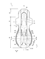
- FIG. 1 is a plan view of the absorbent article in one embodiment.
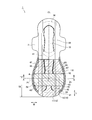
- FIG. 2 is a plan view of the absorbent article as seen from the side opposite to FIG.
- FIG. 3 is a cross-sectional view of the absorbent article taken along line AA in FIG.
- the absorbent article 1 has a front-rear direction L, a width direction W, and a thickness direction T.
- the front-rear direction L is a direction extending from the front side (abdomen side) of the wearer to the rear side (back side), or a direction extending from the rear side of the wearer to the front side.
- the width direction W is a direction orthogonal to the front-rear direction L.
- the thickness direction T is a direction extending from the skin facing surface side T1 of the wearer to the non-skin facing surface side T2, and is a direction orthogonal to the front-rear direction L and the width direction W.
- the skin facing surface side T1 corresponds to the side facing the wearer's skin when in use.
- the non-skin facing surface side T2 corresponds to a side opposite to the skin facing surface side T1, that is, a side facing away from the wearer's skin when used.
- the absorbent article 1 has a crotch region S1, a front side region S2, and a rear side region S3.
- the crotch region S1 is a region facing a wearer's excretion opening (for example, vaginal opening).
- the crotch region S1 is located at the crotch part of the underwear. That is, the crotch region S1 is a region disposed between the wearer's crotch, that is, between the wearer's legs.
- the front side area S2 is located in front of the crotch area S1.
- the front edge of the front region S2 defines the front edge of the absorbent article 1.
- the rear side region S3 is located on the rear side of the crotch region S1.
- the rear edge of the rear side region S3 defines the rear edge of the absorbent article 1.
- the length in the front-rear direction L of the rear side region S3 may be longer than the length in the front-rear direction L of the crotch region S1.
- a wing 3 described later may be provided in the crotch region S1. Further, a hip flap 4 swelled outward in the width direction W may be provided in the rear side region S3.
- the front edge of the wing 3 is defined by the root of the wing 3, and corresponds to the portion located on the front side of the two portions that are recessed most in the width direction W.
- the front edge of the wing 3 may define a boundary between the crotch region S1 and the front side region S2.
- the rear edge of the wing 3 is defined by the root of the wing 3, and corresponds to a portion located on the rear side of the two portions that are recessed most in the width direction W.
- the rear edge of the wing 3 may define the boundary between the crotch region S1 and the rear side region S3.
- a region between the front end edge of the wing 3 and the rear end edge of the wing 3 in the front-rear direction L is referred to as a “wing region”.
- the crotch region S1 is substantially the same region as the wing region. Therefore, it should be noted that in the present specification, the term “inseam area S1” can be read as “wing area”.
- the absorbent article 1 has a skin sheet 10, a non-skin sheet 20, and an absorber 30.
- the skin sheet 10 is provided on the skin facing surface side T ⁇ b> 1 from the absorbent body 30.
- the non-skin surface sheet 20 is provided closer to the non-skin facing surface side T2 than the absorber 30.
- the absorber 30 is provided between the skin sheet 10 and the non-skin sheet 20.
- the skin sheet 10 may have a surface sheet 11 and a side sheet 12.
- the top sheet 11 is a liquid-permeable sheet that transmits liquid such as body fluid.
- the top sheet 11 covers the central portion of the absorber 30 in the width direction W.
- the topsheet 11 may extend in the front-rear direction L from the front side region S2 to the rear side region S3.
- the top sheet 11 is made of any sheet-like material having a structure that allows liquid to permeate, such as a nonwoven fabric, a woven fabric, a perforated plastic sheet, and a mesh sheet. Either natural fibers or chemical fibers can be used as the woven or non-woven material.
- the side sheet 12 covers the outer edge of the top sheet 11 in the width direction W, and extends outward in the width direction W from the top sheet 11.
- the absorbent article 1 has the side sheet 12
- the absorbent article 1 does not need to have the side sheet 12.
- the top sheet 11 may cover the entire absorber 30.
- the side sheet 12 can be made of the same material as the top sheet 11. However, in order to prevent the body fluid adhering to the top sheet 11 from getting over the side sheet 12 and leaking outside the absorbent article 1 in the width direction W, the side sheet 12 has hydrophobicity or water repellency. It is preferable to have.
- the side seat 12 may be disposed on the outer edge of the absorbent body 30 in the width direction W, the wing 3 and the hip flap 4.
- the non-skin surface sheet 20 is a liquid-impermeable sheet.
- the non-skin sheet 20 may be a polyethylene sheet, a laminated nonwoven fabric mainly composed of polypropylene, a breathable resin film, a spunbond, or a sheet in which a breathable resin film is bonded to a nonwoven fabric such as spunlace. it can.
- the non-skin surface sheet 20 is disposed on the non-skin facing surface side T ⁇ b> 2 of the absorber 30 and is disposed across the wing 3 and the hip flap 4.
- the non-skin surface sheet 20 constitutes the non-skin surface of the absorbent article 1.
- positioned at the hip flap 4 are integrated like this Embodiment. It may be constituted by separate sheets.
- the absorber 30 is disposed at least in the crotch region S1 and the rear side region S3. Further, the absorbent body 30 may extend from the crotch region S1 to the front side region S2.
- the absorber 30 includes an absorbent core 31 including an absorbent material that absorbs liquid, and a core wrap 32 that wraps the absorbent core 31.
- the core wrap 32 only needs to cover the absorbent core 31 at least on the skin facing surface side T1 from the absorbent core 31.
- the core wrap 32 includes a first core wrap 321 disposed on the skin facing surface side T1 from the absorbent core 31, a second core wrap 322 disposed on the non-skin facing surface side T2 from the absorbent core 31, and You may have.
- the 1st core wrap 321 and the 2nd core wrap 322 may be comprised from the same sheet
- the absorbent material constituting the absorbent core 31 can be formed from, for example, hydrophilic fibers, pulp, and superabsorbent polymer (SAP).
- SAP superabsorbent polymer
- the core wrap 32 is made of a nonwoven fabric.
- the core wrap 32 may have hydrophobicity. Since the core wrap 32 has hydrophobicity, it is possible to improve leakage resistance.
- the center in the width direction of the first core wrap 321 is disposed on the skin facing surface side T1 of the absorbent core 31.
- the first core wrap 321 is folded back to the non-skin facing surface side T2 of the absorbent core 31 with the outer edge of the absorbent core 31 as a base point.
- 3 is a state in which the first core wrap 321 is folded. In the unfolded state where the first core wrap 321 is not folded back, the center in the width direction of the first core wrap 321 is located at the center in the width direction of the absorbent core 31, and the outer edge 321E of the first core wrap 321 is wider than the absorbent core 31. It extends outward in the direction.
- the outer edge 321E of the first core wrap 321 in the deployed state of the first core wrap 321 may be disposed on the outer side in the width direction from the non-skin facing surface side T2 of the absorbent core 31 or the outer edge of the absorbent core 31.
- the outer edge 321E of the first core wrap 321 of the present embodiment is disposed on the non-skin facing surface side T2 of the second core wrap 322 located on the non-skin facing surface side T2 of the absorbent core 31.
- the outer edge 321E of the first core wrap 321 may extend outward in the width direction of the absorbent core 31, and may be disposed on the non-skin facing surface side T2 of the side sheet 12 and the non-skin facing surface side T2 of the top sheet 11. .
- the absorbent article 1 has the wing 3 and the hip flap 4.
- the wing 3 and the hip flap 4 extend outward in the width direction W from the outer edge of the absorbent core 31 in the crotch region S1.
- the wing 3 and the hip flap 4 may be configured by laminating a side sheet 12, a flap sheet 15, and a non-skin surface sheet 20.
- the flap sheet 15 is disposed across the crotch region S1, the front side region S2, and the rear side region S3.
- the flap sheet 15 is disposed on the wing 3 and the hip flap 4.
- seat 15 should just be arrange
- the flap sheet 15 should just be arrange
- the wing 3 is configured to be foldable toward the non-skin sheet 20 side.
- the wing 3 is folded back to the non-skin facing surface side T2 of the crotch portion of the underwear during use.
- the hip flap 4 is located on the rear side of the wing 3 and is provided in the rear side region S3.
- the hip flap 4 extends outward in the width direction W from the outer edge of the absorbent core 31 in the crotch region S1.
- the region where the hip flap 4 is disposed is located on the outer side in the width direction than the outer edge of the absorbent core 31 in the crotch region S1.
- the hip flap 4 is not folded back during use, and is disposed between the underwear and the wearer's buttocks.
- the hip flap 4 is not provided with an absorbent material.
- the hip flap 4 may be provided with an absorbent material.
- the outer edge 4E of the hip flap 4 has an arc shape that swells outward in the width direction.
- the side edge of the hip flap 4 may be formed in the waveform shape which has many convex parts 4F.
- the plurality of convex portions 4F preferably extend from the outer edge 4E of one hip flap 4 to the outer edge 4E of the other hip flap 4 via the rear end edge of the rear side region S3. Instead, a large number of convex portions 4F may be formed only on the outer edges 4E of the pair of hip flaps 4.
- the width of each convex portion 4F is preferably 20 mm or less, more preferably 10 mm or less. Moreover, it is preferable that the width
- a plurality of convex 4F portions and concave portions between the convex portions 4F are alternately formed on the side edge 4E of the hip flap 4.
- a force is locally applied to the outer edge 4E of the hip flap 4 from the outside, a small number of convex portions 4F provided near the force application point are folded back.
- a gap exists between the convex portions 4F, a force applied to a certain convex portion 4F is difficult to be transmitted to the adjacent convex portion 4F.
- the “thickness” in this specification is measured by the following measurement method.
- a dial gauge PEACOCK manufactured by Ozaki Mfg. Co., Ltd. is used, a measuring element having a diameter of 10 mm is used, a specimen having a size of 30 mm ⁇ 30 mm is prepared, and the thickness of the specimen is measured.
- a measuring device adjusts so that the measurement pressure with respect to a test piece may be 3 g / cm ⁇ 2 >.
- the above-described measurement was performed in each state, and the average value was defined as the length.
- the packaging body In the absorbent article packaged by the packaging body, the packaging body is opened, the folded absorbent article is developed, and the thickness and area of the portion where the basis weight and density are measured are measured. Subsequently, the part which measures a fabric weight and a density is cut out from an absorbent article, and the weight of the cut-out part is measured. Next, parts other than the absorbent core such as the surface sheet and the core wrap are removed from the cut out part, and the weight of the absorbent core is measured. The basis weight is calculated based on the weight of the absorbent core and the area of the portion where the basis weight and density are measured. The density is calculated based on the basis weight and thickness.
- the “length” in this specification is measured by the following measurement method.
- the length of this state of the measurement target part is measured along the measurement target part.
- the above-described measurement was performed in each state, and the average value was defined as the length.
- the absorber 30 has the middle-high part 33 at least in the crotch region S1.
- the middle-high portion 33 may extend from the crotch region S1 to the front side region S2.
- the middle-high portion 33 is disposed across the center line CL in the crotch region S1.
- the center line CL is a line that extends along the front-rear direction L through the center of the absorbent article 1 in the width direction W.
- the middle-high portion 33 means a region where the thickness of the absorbent core 31 is thicker than the thickness of the absorbent core 31 in the region around the middle-high portion 33.
- the basis weight of the absorbent material of the middle-high portion 33 may be higher than the basis weight of the absorbent core 31 in a region other than the middle-high portion 33 in the crotch region S1.
- the middle-high portion 33 may be adjacent to a first low weight portion 41 described later.
- the absorption core 31 on the rear side of the first low weight part 41 is thinner than the thickness of the middle high part 33. More preferably, the absorption core 31 of the entire rear side region S3 is thinner than the thickness of the middle-high portion 33.
- the middle-high part 33 has the thickest highest part and the inclined part connected to the highest part.
- the inclined portion may be disposed between the highest portion and a front pressing portion 81 described later, and between the highest portion and the first low weight portion 41.
- the absorbent core 31 may have a first low weight portion 41, a second low weight portion 42, and a third low weight portion 43.
- the “low weight portion” means a region composed of the absorbent core 31 having a lower weight than the surrounding absorbent core 31 or a region not having the absorbent core 31.
- the “low weight portion” is a concept including a region where the weight of the absorbent core 31 is zero.
- the “low weighted portion” may be a slit that penetrates the absorption core 31 in the thickness direction T.
- the slit has a design basis weight of zero, but may be a region where an absorbing material mixed from the periphery is disposed.
- the length in the width direction W of the slit is preferably 1 mm to 5 mm. For example, if the length in the width direction of the slit is less than 1 mm, the absorbent material may flow between the slits, and the deformation base point of the absorbent core 31 may not be configured. In addition, if the length of the slit in the width direction exceeds 5 mm, the wearer may feel anxiety about leakage of body fluid.
- the basis weight of the absorbent core 31 in the low basis weight portions 41 to 43 is preferably 150 g / m 2 or less, more preferably 100 g / m 2 or less. Further, the basis weight of the absorbent core 31 in the low basis weight portions 41 to 43 is further preferably substantially 0 g / m 2 . Further, the basis weight of the absorbent core 31 in the low basis weight portions 41 to 43 is preferably 60% or less of the basis weight of the absorption core 31 (excluding the middle and high portions) around the low basis weight portions 41 to 43, and is 50% or less. More preferably.
- the core wrap 32 may wrap the entire absorbent core 31 across the low weight portion. In this case, even if the absorbent core 31 is divided into a plurality of regions, the absorbent body 30 is integrally formed by the core wrap 32.
- the first low weight portion 41, the second low weight portion 42, and the third low weight portion 43 serve as a boundary where the rigidity of the absorber 30 changes. Therefore, the 1st low weight part 41, the 2nd low weight part 42, and the 3rd low weight part 43 are equivalent to the area
- the first low weight portion 41 extends in the width direction W between the crotch region S1 and the rear side region S3.
- the first low weight portion 41 may extend linearly along the width direction W or may extend along a curve along the width direction W.
- the first low basis weight portion 41 may be provided on the rear side of the wing 3 center in the front-rear direction L and on the front side of the rear edge of the absorber 30.
- the first low weight part 41 may be provided so as to straddle the rear edge of the wing 3 in the front-rear direction L.
- the first low weight portion 41 has a curved shape in which the center in the width direction W of the first low weight portion 41 protrudes rearward. More specifically, the center of the first low weight portion 41 in the width direction W is located behind the outer edge of the first low weight portion 41.
- the length of the first low weight portion 41 in the front-rear direction L may be constant or may not be constant.
- the crotch region S1 located on the front side of the first low weight portion 41 is sandwiched between both legs, and is easily subjected to a twisting force due to the movement of the legs.
- the absorbent article 1 since the first low-weighted portion 41 has a curved shape, the absorbent article 1 can easily follow the torsion of the body and easily escape deformation due to the movement of the body.
- the length of the first low weight portion 41 in the width direction W is 25 mm or more. Thereby, it can suppress that the motion of the absorber 30 in crotch region S1 is transmitted to back side region S3. More preferably, the first low weight portion 41 extends from one end of the absorber 30 to the other end in the width direction W.
- the front edge of the first low weight portion 41 may define the rear edge of the crotch region S1, and the rear edge of the first low weight portion 41 defines the front edge of the rear region S3. May be.
- the absorbent material constituting the absorbent core 31 moves between the crotch region S1 and the rear side region S3. It becomes difficult. Therefore, it can suppress more that the absorption material which comprises the absorption core 31 concentrates locally by the operation
- the length of the first low weight portion 41 in the front-rear direction L is preferably 10 mm or more and 50 mm or less, more preferably 10 mm or more and 30 mm or less, at the position of the center line CL of the absorbent article 1.
- the absorbent article 1 includes the first low-weighted portion 41, so that independent deformation can be realized in the crotch region S1 and the rear side region S3. More specifically, the first low-weighted portion 41 has a length of 10 mm or more, and the first low-weighted portion 41 extends from one end to the other end, whereby the absorbent article 1 is the first. It is possible to deform in the direction other than the thickness direction T at the low basis weight 41, and the deformation of the crotch region S1 and the rear side region S3 can be independently deformed without interfering with each other.
- the crotch region S1 and the rear region S3 are independently deformed.
- the crotch region S1 and the rear side region S3 can continue to fit to the shape of the body.
- the absorbent article 1 can make the crotch region S1 follow the body and follow the rear side region S3 according to the movement of the body.
- the second low weight portion 42 is located in the center in the width direction of the absorbent core 31 in the rear side region S3.
- the second low weight portion 42 extends in the front-rear direction L along the center line CL of the absorbent article 1 in the rear side region S3.
- the second low weight portion 42 may extend linearly in the front-rear direction L.
- the second low weight portion 42 is preferably connected to the first low weight portion 41.
- the second low weight portion 42 corresponds to a front and rear low weight portion.
- the absorbent material constituting the absorbent core 31 by the first low weight portion 41 and the second low weight portion 42 is the crotch region S1 (or wing region), the right side portion of the rear side region S3, and the left side of the rear side region S3. It becomes difficult to move between parts. Thereby, it can suppress that the absorption material which comprises the absorption core 31 concentrates locally by the operation
- the center in the width direction W of the absorption core 31 in the rear side area S3 is the second low weight part. It bulges toward the wearer with 42 as a vertex. Therefore, the 2nd low weight part 42 protrudes toward a wearer's skin side during wear. Since the second low weight portion 42 extends along the front-rear direction L in the rear side region S3, it is easy to fit along the wearer's crack. Furthermore, as described above, the absorbent article 1 is easily deformed independently in the crotch region S1 and the rear side region S3 by the first low weight portion 41. That is, the absorbent article 1 can fit in accordance with the shape of the body in both the crotch region S1 and the rear side region S3 by deforming independently in the crotch region S1 and the rear side region S3.
- the rear end edge of the second low weight part 42 may be located behind the center of the rear side region S3 in the front-rear direction L. Further, the rear end edge of the second low weight portion 42 may be located on the rear side of the position P1 of the maximum width of the hip flap 4. The position P1 of the maximum width of the hip flap 4 is located on the rear side of the center of the rear side region in the front-rear direction L.
- the length of the second low weight portion 42 in the front-rear direction L is preferably 120 mm or more, and more preferably 150 mm or more. Preferably, the length of the second low weight portion 42 in the width direction W is 1 mm or more and 5 mm or less.
- a groove (crack) between the hips exists in a region from the back to the caudal bone from the back of the perineum.
- the second low weight portion 42 is disposed in the region of the wearer's rupture.
- the third low weight part 43 extends outward in the width direction W from the second low weight part 42 in the rear side region S3.
- the third low weight part 43 may be connected to the second low weight part 42.
- the third low weight portion 43 corresponds to a width low weight portion.
- the front edge line of the third low weight portion 43 may extend substantially parallel to the width direction W inside the width direction W.
- the front edge line of the third low weight portion 43 may protrude forward on the outer side in the width direction W.
- the rear edge line of the third low weight portion 43 may be inclined forward as it goes from the inner side to the outer side in the width direction W. Since the rigidity changes with the third low weight portion 43 as a boundary, the third low weight portion 43 serves as a base point for deformation of the absorbent article 1.
- a deformation base point extending in the width direction W is formed in the rear region S3 of the absorbent article 1. Since the absorbent core 31 in the rear side region S3 can be deformed with the third low weight portion 43 as a base point, the absorbent article 1 can easily fit along the roundness along the front-rear direction L of the body. In particular, since the rear edge line of the third low weight portion 43 has a shape that inclines forward as it goes from the inner side to the outer side in the width direction W, it is easy to be arranged along the roundness of the wearer's buttocks.
- the outer edge of the third low weight portion 43 in the width direction W is located inside the outer edge of the absorbent core 31 in the rear region S3.
- a plurality of third low weight portions 43 may be provided at intervals in the front-rear direction L.
- the 3rd low weight part 43 comprises the music part in this Embodiment.
- the third low weight portion 43 is configured such that the absorbent article 1 can be bent in the thickness direction T.
- the “curved portion” only needs to extend along the width direction W, may be parallel to the width direction W, or may be inclined with respect to the width direction W.
- the “curved portion” may be a configuration that becomes a deformation base point of the absorbent core 31, may be configured by a low weight portion, or may be a compressed portion in which the absorbent core 31 is compressed in the thickness direction T. .
- the absorbent core 31 has a high basis weight 45 located on the outer side in the width direction than the second low basis weight 42 in the rear side region S3.
- the basis weight of the absorbent material of the high basis weight 45 is lower than the basis weight of the absorbent material of the surrounding absorbent core 31.
- the high basis weight 45 is a portion of the absorbent core 31 in the rear side region S3 excluding the second low basis weight 42 and the third low basis weight 43.
- the second low weight portion 42, the third low weight portion 43, and the high weight portion 45 are covered with the topsheet 11.
- the density of the absorbent core 31 may be substantially constant.
- the state where the density of the absorbent core 31 is constant is a state where the absorbent core 31 is not partially pressed after the absorbent material is laminated.
- the absorption core 31 has a plurality of regions with different basis weights. Specifically, the basis weight of the middle high portion 33, the basis weight of the region outside the middle high portion 33 in the width direction in the crotch region S1, the basis weight of the high basis weight portion 45 of the rear side region S3, and the low basis weight of the rear side region S3 This is different from the basis weight of the part (the second low weight part 42 and the third low weight part 43).
- the weight of the absorbent material constituting the absorbent core 31 is as follows: the middle-high portion 33, the crotch region S1, the region outside the middle-high portion 33 in the width direction, the high-weighted portion 45 of the rear region S3, the rear region S3. It is comprised so that it may become low in the order of the low weight part.
- Pressing part Absorbent article 1 has a pressing part formed by compressing at least absorption core 31 in thickness direction T.
- This pressing part may have a front pressing part 81, a longitudinal pressing part 82, and a pair of rear pressing parts 84.
- the front pressing part 81 is provided at least in the crotch region S1.
- the front pressing part 81 may extend from the crotch region S1 to the front side region S2.
- the front pressing part 81 may be formed by compressing the topsheet 11, the absorbent core 31, and the core wrap 32 in the thickness direction T.
- the front side compression part 81 has a section along the front-rear direction L provided on both sides in the width direction W of the middle-high part 33.
- the front side compressed portion 81 may define a side edge in the width direction W of the middle-high portion 33.
- the longitudinal pressing portion 82 is provided on both sides of the center line CL, more specifically, the second low weight portion 42 in the rear side region S3.
- the longitudinal pressing part 82 may be formed by the absorber 30 and the surface sheet 11 being compressed in the thickness direction T.
- the longitudinal pressing part 82 should just be provided in the absorption core 31 and the surface sheet 11 at least.
- the longitudinal pressing portion 82 extends in the front-rear direction L on both outer sides in the width direction W than the second low weight portion 42.
- the longitudinal pressing part 82 should just extend in the front-back direction L at least in the shape of a line or a dotted line.
- the longitudinal pressing part 82 may extend linearly in parallel to the front-rear direction L, or may extend in a curved manner inclined with respect to the front-rear direction L.
- the longitudinal pressing part 82 may be formed in front of the position P1 of the maximum width of the hip flap 4.
- the center in the width direction W of the absorber in the rear side region S3 is the top of the second low weighted portion 42.
- the longitudinal pressing portions 82 are disposed on both sides of the second low weight portion 42 in the width direction W, and serve as a base point for deformation when the second low weight portion 42 is raised on the wearer side.
- the front pressing part 81 and the longitudinal pressing part 82 may be divided in the front-rear direction L.
- By dividing the front pressing part 81 and the longitudinal pressing part 82 it is possible to suppress the propagation of force in the crotch region S1 and the rear side region S3. Therefore, by independently deforming the crotch region S1 and the rear side region S3, it is possible to fit the body shape in both the crotch region S1 and the rear side region S3.
- the front side pressing part 81 and the longitudinal pressing part 82 may be continuously connected.
- the pair of rear side compression parts 84 is provided on both sides of the center line CL in the rear side region S3.
- the rear side compressed portion 84 may be formed by compressing the absorbent body 30 and the top sheet 11 in the thickness direction T.
- the back side compression part 84 should just be provided in the absorption core 31 and the surface sheet 11 at least.
- the pair of rear pressing parts 84 are provided apart from each other with a center line CL passing through the center in the width direction W of the absorbent article 1.
- the pair of rear side compressed parts 84 may be located on the rear side of the position P1 of the maximum width of the hip flap 4.
- the pair of rear squeezed portions 84 are located near the rear end of the rear region S3. Specifically, the pair of rear pressing parts 84 are located in the vicinity of the region facing the wearer's sacrum.
- the rear side compressed portion 84 may extend along the front-rear direction L in a line shape or a dotted line shape. In addition, even if it is slightly inclined or curved with respect to the front-rear direction L, it is considered that the rear compressed portion 84 extends along the front-rear direction L.
- the pair of rear pressing parts 84 may extend along the front-rear direction L partially or entirely.
- a pair of rear side compression parts 84 have a wide section where the distance of the width direction W spreads toward the rear side. That is, the rear side compression part 84 inclines outside the width direction W as it goes to the rear side.
- the pair of rear pressing parts 84 is located on the rear side of the position P1 of the maximum width of the hip flap 4 in the width direction W, and the pair of rear pressing parts 84 has a distance in the width direction W toward the rear side. It has a wide section that widens.
- the maximum width of the hip flap 4 in the width direction W is located behind the center of the rear side region S3 in the front-rear direction L.
- the wide area sandwiched by the wide sections corresponds to the vicinity of the wearer's sacrum. There are no compressed parts in this area, and there are a pair of relatively high rear compression parts 84 on both sides of this area.
- the wide area is maintained on a relatively flat surface. Since the relatively flat surface hits the skin near the sacrum, the influence on the wearer's skin can be reduced. Further, since the wide region is maintained on a relatively flat surface, the convex deformation by the second low-weight 42 portion located on the front side of the wide region can be made flat.
- the pair of rear pressing parts 84 are arranged so as to partition between a region facing the vicinity of the sacrum and a part facing the thick part of the buttocks. Since the buttocks move relatively vigorously, the portion of the absorbent article 1 that faces the buttocks is also easy to move according to the movement of the wearer. The movement of the absorbent article 1 is not easily transmitted to the region facing the sacrum, that is, the wide region, by the pair of relatively high-rear compression parts 84. As a result, the wide region can be maintained on a relatively flat surface, and the influence on the wearer's skin can be reduced. Moreover, it is preferable that there is no highly rigid pressing part in a wide area
- the pair of longitudinal pressing portions 82 are disposed away from the pair of rear pressing portions 84. Thereby, it is possible to suppress the movement of the absorption core 31 behind the rear side area S3 from following the movement of the absorption core 31 ahead of the rear side area S3.
- the absorbent core 31 in front of the rear side region S3 may move relatively greatly in accordance with the movement of the wearer's buttocks. Even in this case, since the pair of longitudinal pressing portions 82 and the pair of rear pressing portions 84 are separated from each other, the movement of the absorbent core 31 behind the rear side region S3 is alleviated. Therefore, since the movement of the absorbent core 31 in the wide region is relieved, it is possible to reduce the stimulus given to the wearer near the sacrum.
- the pair of longitudinal pressing parts 82 are disposed away from the pair of rear pressing parts 84.
- the distance between the pair of longitudinal pressing parts 82 and the pair of rear pressing parts 84 is preferably at least 3 cm, more preferably at least 5 cm.
- the length of the tip side of a general female first joint is 1.5 to 2.5 cm. By being longer than the length on the tip side than the first joint, when the finger touches or when the touched finger moves a little, the finger does not hit the compressed portion, and the wearer softens the surface of the absorbent article 1 I can feel it.
- the section between the pair of longitudinal pressing parts 82 and the pair of rear pressing parts 84 where the pressing part is not formed constitutes a non-squeezing region 52 described later.
- the section in which the pressing part is not formed may straddle the position P1 of the maximum width of the hip flap 4.
- the absorbent article 1 includes a first pressing unit 85 and a second pressing unit formed by pressing at least two of the sheets constituting the skin sheet 10 and the non-skin sheet 20 in the thickness direction T. 87 and the 3rd pressing part 86 may be included (refer FIG. 1).
- the first pressing part 85, the second pressing part 87, and the third pressing part 86 may be formed along the outer edge 4 ⁇ / b> E of the hip flap 4.
- the absorbent article 1 is provided with an adhesive part 60 having an adhesive for fastening the absorbent article 1 to the undergarment.
- the adhesive part 60 is configured to detachably engage the absorbent article 1 with the underwear, and constitutes an engaging part.
- an engaging part is not limited to an adhesion part, For example, a hook member may be sufficient.
- the adhesive part 60 includes a first main body adhesive part 61, a second main body adhesive part 62, a wing adhesive part 63, and a hip flap adhesive part 64. These adhesive portions 61 to 64 are provided on the non-skin facing surface side T2 of the non-skin surface sheet 20.
- the adhesive portions 61 to 64 may be covered with a release sheet in a state before use. The release sheet prevents the adhesive of the adhesive portions 61 to 64 from being deteriorated before use. The release sheet is removed by the wearer during use.
- the first main body adhesive portion 61 is disposed in front of the second main body adhesive portion 62.
- the first main body adhesive portion 61 and the second main body adhesive portion 62 extend in the front-rear direction L.
- the first main body adhesive portion 61 is disposed away from the second main body adhesive portion 62 in the front-rear direction L.
- the first main body adhesive portion 61 may be disposed on the front side of the first low weight portion 41 and straddling the crotch region S1 and the front side region S2.
- the second main body adhesive portion 62 is disposed behind the first low weight portion 41 and in the rear region S3. It is preferable that the 1st main body adhesion part 61 and the 2nd main body adhesion part 62 are not provided on the centerline CL.
- the wing adhesive portion 63 is provided on the wing 3.
- the hip flap adhesive portion 64 is provided on the hip flap 4.
- the first low weight portion 41 is preferably arranged in a region that does not overlap the adhesive portions 61 to 64 in the thickness direction T. More specifically, the first low weight portion 41 is provided in a region between the first main body adhesive portion 61 and the second main body adhesive portion 62.
- the second low weight portion 42 is preferably arranged in a region that does not overlap with the adhesive portions 61 to 64 in the thickness direction T. More specifically, the second low weight portion 42 is provided between the plurality of second main body adhesive portions 62.
- the pair of longitudinal pressing portions 82 is preferably provided in a region overlapping the second main body adhesive portion 62.
- FIG. 4 is a schematic cross-sectional view of the top sheet 11.
- the topsheet 11 has a first layer 111 and a second layer 112.
- the surface sheet 11 is illustrated by 1 layer, in detail, the surface sheet 11 consists of 2 layers, as shown in FIG.
- the first layer 111 constitutes the skin facing surface of the absorbent article 1.
- the second layer 112 is disposed on the non-skin facing side T2 of the first layer 111.
- the first layer 111 and the second layer 112 are nonwoven fabrics.
- the diameter of the fiber constituting the second layer 112 is larger than the diameter of the fiber constituting the first layer 111.
- the fiber diameter of the first layer 111 is 1.3 dtex, and the fiber diameter of the second layer 112 is 2.2 dtex. More preferably, the diameter of the fibers of the first layer 111 is preferably 0.5 dtex or more and less than 2.0 dtex. When the fiber diameter of the first layer 111 is 0.5 dtex or more, the nonwoven fabric can be stably manufactured using the fiber. Moreover, when the diameter of the fiber of the first layer 111 is less than 2.0 dtex, it is easy to feel softness when the wearer touches with a finger, and a favorable evaluation can be obtained also in examples described later. .
- the basis weight of the fibers of the second layer may be higher than the basis weight of the fibers of the first layer.
- the basis weight of the fibers of the first layer 111 is 7 g / m 2
- the diameter of the fibers of the second layer 112 is 18 g / m 2 .
- the topsheet 11 may be integrated after the first layer 111 and the second layer 112 are separately formed, or may be formed in a state where the first layer 111 and the second layer 112 are integrated.
- FIG. 5 is a diagram showing a compressed region 51 and a non-compressed region 52 in the plan view of the absorbent article 1 shown in FIG.
- the squeezed region 51 and the non-squeezed region 52 are shown with different oblique lines.
- the rear side area S3 has a pressing area 51 where the pressing part is arranged and a non-squeezing area 52 where the pressing part is not arranged.
- region 51 is a pressing part which compressed the absorption core 31 and the surface sheet 11, ie, the pressing part provided in the absorption core 31 and the surface sheet 11, and is longitudinal in this Embodiment.
- the pressing area 51 is an area where at least one of the longitudinal pressing portion 82 and the rear pressing portion 84 is disposed. More specifically, the pressing region 51 includes a region where the longitudinal pressing unit 82 is disposed and a region extending in the width direction W from the region where the longitudinal pressing unit 82 is disposed. Moreover, the compression area
- the non-squeezing region 52 is a region where the pressing parts (the longitudinal pressing part 82 and the rear pressing part 84 in the present embodiment) provided in the absorbent core 31 and the top sheet 11 are not disposed.
- the non-compressed region 52 continuously extends from one end of the absorbent body 30 to the other end along the width direction W.
- region 52 is the concept containing the area
- the pressing areas 51, the non-squeezing areas 52, and the pressing areas 51 are alternately arranged from the front.
- Part of the absorbent core 31 provided in the rear side region S3 is disposed in the non-squeezed region 52. Moreover, it is preferable that a part of the second low weight portion 42 extends in the non-compressed region 52. It is more preferable that the second low weight portion 42 penetrates the non-squeezed region 52 along the front-rear direction L.
- the non-squeezed region 52 may overlap with at least one low weight part and at least one high weight part 45.
- the non-squeezed region 52 of the present embodiment overlaps the high basis weight portion 45, the second low basis weight portion 42, and the third low basis weight portion 43.
- the third low weight parts 43 and the high weight parts 45 are alternately arranged along the front-rear direction L.
- the second low weight portions 42 and the high weight portions 45 are alternately arranged along the width direction W.
- the wearer when the wearer traces the non-squeezed region 52 along the front-rear direction L, the skin facing surface side T1 of the third low weight portion 43 and the skin facing surface side T1 of the high weight portion 45 are traced. Further, when the wearer traces the non-compressed region 52 along the width direction W, the skin facing surface side T1 of the second low weight portion 42 and the skin facing surface side T1 of the high weight portion 45 are traced. Therefore, the wearer easily feels the swelling of the absorbent core 31 due to the change in the basis weight of the absorbent core 31 by tracing the skin facing surface side T1 of the non-compressed region 52.
- At least a part of the non-compressed region 52 may be disposed in a rear end region 53 that extends forward from the rear end edge of the absorbent article 1.
- the length of the rear end region 53 in the front-rear direction L is 25% of the total length along the front-rear direction L of the absorbent article 1.
- at least a part of the non-compressed region 52 may be disposed in the rear end region 53, and the non-compressed region 52 may extend forward from the rear region.
- the non-compressed region 52 may be disposed on an imaginary line extending in the width direction W from the maximum width position P1 of the hip flap 4.
- at least a part of the non-compressed region 52 only needs to be arranged on the virtual line.
- the length in the front-rear direction L of the non-compressed region 52 may be 30 mm or more. By being 30 mm or more, it becomes longer than the length (15 mm to 25 mm) on the tip side than the first joint of the finger of a general wearer (adult). Therefore, it is possible to receive a soft impression without touching the squeezed part when pressed with the belly of the finger. Moreover, it is about twice as long as the first joint of the wearer's (adult) finger, so that even when the finger is traced or touched with a plurality of fingers, the compressed portion is not touched. A soft impression can be received.
- the length of the non-compressed region 52 in the front-rear direction L may be shorter than the length of the rear side region S3 in the front-rear direction L.
- the non-compressed region 52 preferably straddles the rear end edge of the adhesive portion 60 in the rear side region S3 in the front-rear direction L.
- the non-compressed region 52 When the non-compressed region 52 straddles the rear end edge of the adhesive portion 60 in the rear side region S3 in the front-rear direction L, the non-compressed region 52 is relatively soft when the wearer completes the operation of pressing with the finger. Therefore, the wearer can have a soft impression of the absorbent article 1 immediately before wearing, and can increase expectation.
- At least a part of the non-compressed region 52 may be disposed in a rear end region extending from the rear end edge of the absorbent article 1 to the front side.
- the wearer presses the absorbent article with a finger up to the vicinity (rear end area) of the rear end edge of the absorbent article at the time of wearing, and the wearing operation is performed in the rear end area. Found out to complete.
- the range in the vicinity of the rear end edge of the absorbent article is along the front-rear direction L of the absorbent article from the rear end edge of the absorbent article to the front side. It was found that the range extends 25% of the total length.
- the wearer can feel softness when the wearer completes the wearing.
- the wearer can wear the absorbent article 1 in a state where the wearer feels softness just before wearing and has a sense of expectation.
- the pressing area 51 may be disposed on the rear side of the position P1 of the maximum width of the hip flap 4 in the width direction W.
- a rear squeezing portion 84 is provided in the squeezing region 51 on the rear side of the position P1 having the maximum width of the hip flap 4.
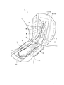
- FIG. 6 is a perspective view schematically showing the absorbent article 1 in use.
- the wearer fixes the crotch region S1 disposed in the crotch of the wearer to the underwear, and then fixes the rear side region S3 to the underwear. More specifically, the wearer brings the first main body adhesive portion 61 into contact with the crotch region of the underwear and causes the second main body adhesive portion 62 to contact with the underwear behind the crotch region.
- the wearer turns the wing 3 back to the non-skin facing surface side T2 of the underwear, and makes the wing adhesive portion 63 abut on the non-skin facing surface of the crotch region of the underwear. Further, the wearer brings the hip flap adhesive portion 64 into contact with the underwear behind the crotch region.
- the wearer places his / her hand on the skin sheet 10, for example, presses the absorbent article 1 against the underwear while tracing the skin-facing surface of the absorbent article 1 with his / her finger and holds the adhesive part 60. Fix through.
- the wearer presses the skin sheet 10 (part A in FIG. 6) in the crotch region S1 with a finger, and then moves the finger backward while tracing the skin sheet 10 with the finger (arrow X in FIG. 6). ), And press the skin sheet 10 (B portion in FIG. 6) in the rear side region S3 with a finger.
- the wearer presses the absorbent article 1 against the underwear at a portion including the first joint from the tip of the finger in order to firmly press the absorbent article 1 against the underwear. By wearing in this way, the absorbent article 1 is fixed to the underwear.
- the wearer Since the non-squeezing region 52 is provided in the rear region S3 of the absorbent article 1 of the present embodiment, the wearer places his / her finger along the rear side from the front side (inseam region side, part A in FIG. 6). When the slide is moved (arrow X in FIG. 6), the non-compressed region 52 is touched (B portion in FIG. 6). When the wearer traces the surface of the absorbent article 1 with a finger, the wearer feels softness without feeling the hardness of the squeezed portion for at least a certain period. Therefore, the wearer can grasp the softness of the absorbent article 1 before wearing, and can obtain a sense of expectation for the comfort of the absorbent article 1.
- the diameter of the fiber of the 1st layer 111 which touches a wearer's hand is comparatively small. Since the first layer 111 is soft to the touch, the wearer can feel softness when touched by hand. Further, when the wearer presses the absorbent article 1 to fix it to the undergarment or the like, a repulsive force is easily obtained by the second layer 112 made of relatively thick fibers. Therefore, when the wearer traces the surface sheet 11 with the finger, the skin facing surface of the surface sheet 11 is pushed back to the finger side by the repulsive force of the second layer 112, and the wearer touches the skin facing surface of the surface sheet 11 with the finger. It becomes easy to continue touching. Since the wearer continues to touch the soft first layer 111, the wearer can continue to feel the softness of the topsheet 11.
- the nonwoven fabric which comprises the core wrap 32 which covers the absorption core 31 has high elongation compared with a tissue. Therefore, when the wearer slides the finger touching the absorbent article 1 or presses the finger with the finger, the nonwoven fabric that is the core wrap 32 extends, and the wearer has the skin facing surface of the absorbent article 1. A feeling of following the hand can be obtained. More specifically, when the finger is traced on the first layer 111 of the top sheet 11, the finger moves on the skin facing surface of the first layer 111. At this time, since the core wrap 32 positioned at the root of the surface touched by the finger has a high elongation, the core wrap 32 as the root extends following the movement of the finger.
- the first layer 111 is pulled by following the movement of the finger, and the finger does not immediately leave the first layer 111, or the first layer It feels as if the fibers of 111 are clinging to the finger and the fibers are slowly separated from the finger. Therefore, the wearer can continue to feel the softness not by the point but by the surface.
- the wearer When the wearer traces the skin facing surface of the absorbent article 1 with a finger, the wearer feels softness without feeling the hardness of the squeezed part for at least a certain period.
- the wearer can grasp the softness of the absorbent article 1 before wearing, and can obtain a sense of expectation for the comfort of the absorbent article 1.
- the finger sensation is sharpened. Therefore, the sensation felt soft with a finger tends to remain with a relatively strong impression in the head. Therefore, the wearer can easily maintain a soft impression during wearing by feeling soft with a finger.
- the rear side area S3 is particularly surely fixed to the underwear. If the rear side area S3 of the absorbent article 1 is not fixed to the absorbent article 1, when the underwear is lifted after wearing, the absorbent article 1 turns over and the absorbent article 1 comes off, or the absorbent article 1 turns over and the adhesive parts stick together. Therefore, the wearer tries to fix the back side area S3 of the absorbent article 1 with his / her finger to fix the underwear. Since the non-squeezing region 52 is provided in the rear side region T3 of the absorbent article 1, when the wearer tries to fix the rear side region S3 with certainty, the wearer can reduce the softness of the absorbent article 1. I can grasp it.
- the non-compressed region 52 overlaps the second main body adhesive portion 62 of the rear side region S3.
- the wearer tries to press the second main body adhesive portion 62 of the rear side region S3 against the underwear when the rear side region S3 is securely fixed to the underwear. Therefore, when the wearer tries to fix the rear side region S3 through the second main body adhesive portion 62 by overlapping the second main body adhesive portion 62 and the non-compressed region 52, the finger is in the non-compressed region. 52 is easy to touch.
- the wearer can grasp the softness of the absorbent article 1 during the mounting operation, and can increase expectations for the absorbent article 1.
- the non-squeezed region 52 may be arranged so as to overlap the low weight portion and the high weight portion 45.
- the wearer traces the skin facing surface of the non-squeezed region 52, the skin facing surface side T1 of both the high weighted portion 45 and the low weighted portion can be traced, and the swelling of the absorbent core 31 can be easily felt by the change in the weight. Become.
- a plurality of the third low weight portions 43 as the width low weight portions may be arranged at intervals in the front-rear direction L.
- the plurality of third low weight portions can be traced.
- the second low weight portion 42 as the front and rear low weight portion may be arranged so as to overlap the non-squeezed region 52.
- the second low weight portion 42 serves as a guide extending in the front-rear direction L, and the wearer can easily slide the hand pressing the crotch region S1 rearward along the second low weight portion 42. The wearer can feel the softness of the absorbent article 1 by touching the non-squeezed region 52 when moving backward along the second low weight portion 42.
- the non-compressed area 52 may be disposed on a virtual line extending in the width direction W from the position P1 having the maximum width of the hip flap 4.
- the wearer tries to securely fix the position P1 of the maximum width of the hip flap 4 that is most swollen in the rear side region S3 in order to prevent the hip flap 4 from being swung. Therefore, the wearer presses with a finger on the position P1 of the maximum width of the hip flap 4 or an imaginary line extending in the width direction W from the position P1 of the maximum width.
- the wearer can easily touch the non-squeezed region 52, and the wearer may feel softness. it can.
- the pressing area 51 may be disposed on the rear side of the position P1 of the maximum width of the hip flap 4 in the width direction W.
- the wearer feels one softness of the absorbent article by the non-squeezed region 52 on the imaginary line extending in the width direction 4 from the position P1 of the maximum width of the hip flap 4.
- a wearer can touch a pressing part by moving a finger back rather than the said non-pressing area
- the wearer can grasp the position of the rear edge of the absorbent article 1 by the change in the hardness of the skin facing surface of the absorbent article 1. Therefore, the wearer can obtain a sense of expectation for the wearing feeling of the absorbent article 1 and can feel secure that it can be securely fixed to the underwear until reaching the rear edge of the absorbent article 1.
- the diameter of the fibers constituting the first layer may be less than 2.0 dtex.
- the outer edge 321E of the first core wrap 321 may be disposed on the outer side in the width direction from the non-skin facing surface side T2 of the absorbent core 31 or the outer edge of the absorbent core 31. In other words, the outer edge 321E of the first core wrap 321 may not be disposed on the skin facing surface side T1 of the absorbent core 31. Without forming a step due to the outer edge of the core wrap 32 on the skin facing surface of the absorbent article 1, it is easy to maintain the skin facing surface of the absorbent article 1 in a smooth state. When the wearer touches the top sheet 11, it is difficult for the wearer to feel a step due to the presence or absence of the core wrap 32, and it becomes easy to obtain a smooth and skin-friendly image.
- the absorbent core 31 may not be partially compressed, and the density of the absorbent material may be constant. Since the portion hardened by the compression is not provided in the absorbent core 31, the entire region where the absorbent core 31 is disposed becomes soft. The wearer can easily feel the softness of the absorbent core 31 and can easily expect the feeling of wearing.
- the absorbent core 31 may have a plurality of areas with different basis weights, and the areas with different basis weights may be configured such that the basis weight changes stepwise. Since the basis weight changes in stages in a plurality of regions, a plurality of irregularities are formed on the skin facing surface of the absorbent article 1. The wearer tends to feel swelling due to the unevenness of the absorbent core 31 when tracing with a finger. Further, the absorbent core 31 is easily deformed with the boundary where the basis weight is changed as a base point, and is easily deformed flexibly following the movement of the body when worn. Therefore, since the absorption core 31 follows the movement of the body, the wearing feeling is improved.
- the nonwoven fabric according to the present invention (Example) and the nonwoven fabric not having the configuration of the present invention (Comparative Example) are comparatively evaluated.
- the experiment was conducted.
- the comparative evaluation experiment in order to evaluate the surface friction and roughness of the nonwoven fabric in order to evaluate the non-woven fabric's rough sliding feeling, the non-woven fabric was evaluated in order to evaluate the hardness and softness of the nonwoven fabric.
- the compression characteristics in the thickness direction were examined and compared.
- the nonwoven fabric according to the example and the nonwoven fabric according to the comparative example have different fiber diameters. In the nonwoven fabric of the example, the fiber diameter of the first layer is thinner than that of the second layer. In the nonwoven fabric of the comparative example, the fiber diameter of the first layer is thicker than that of the second layer.
- MMD surface roughness
- SMD surface roughness
- Table 2 shows the comparative evaluation results.
- the absorbent articles of Examples 1 and 2 and the absorbent articles of Comparative Examples 1 to 5 were compared, and the touch feeling during wearing, the kinking during use, and the surface during use were compared.
- the comfort was evaluated.
- the absorbent articles of Example 1 and Example 2 and the absorbent articles of Comparative Examples 1 to 4 are different in the diameter of the fibers constituting the first layer and the second layer of the topsheet, but other configurations are different. The same.
- Table 2 shows the difference in configuration between the example and the comparative example.
- the absorbent article of Example 1 and Example 2 and the absorbent article of Comparative Example 5 are different in the shape of the absorbent core and the diameter of the fibers constituting the first layer and the second layer of the topsheet.
- the configuration is the same.
- the absorbent article of Comparative Example 5 does not have a low basis weight portion and a high basis weight portion in the rear side region, and the basis weight of the rear side region is constant.
- the test for comparative evaluation was conducted by 100 women using napkins. In the evaluation test, the practitioner was asked to touch the target sample and used overnight, and the following questions were asked.
- QUESTION 1 “Is the texture softer than the napkin that I usually use?”
- QUESTION 2 “Did you not get stuck during wearing compared to the napkin that you normally use?
- QUESTION 3 “Is it more comfortable to wear than wearing a napkin that I usually use?”
- a sample having a ratio of the number of people who answered “Comfortable to use” or “Fit and comfortable” to Question 3 was evaluated as “x” because the sensory evaluation was not good.
- the fiber diameter of the first layer is 2.0 dtex or less
- the fiber diameter of the second layer is preferably larger than the fiber diameter of the first layer. More specifically, when the fiber diameter of the first layer is 2.0 dtex or less and the fiber diameter of the second layer is thicker than the fiber diameter of the first layer, the touch comfort during wearing and the comfort during use can be obtained. I understood it.
- the shape of the absorber 30 of this invention it turned out that it does not depend on in use.
- Absorbent article 10 Skin sheet 11: Top sheet 111: First layer 112: Second layer 12: Side sheet 15: Flap sheet 20: Non-skin sheet 30: Absorbent body 31: Absorbing core 32: Core wrap 321 : First core wrap 322: second core wrap 41: first low weight part 42: second low weight part 43: third low weight part 45: high weight part 61: first main body adhesive part 62: second main body adhesive part 63 : Wing adhesive part 64: Hip flap adhesive part 81: Front side compressed part 82: Long side compressed part 84: Rear side compressed part L: Front and rear direction W: Width direction T: Thickness direction S1: Inseam area S2: Front side area S3: Rear side Area CL: Center line
Landscapes
- Health & Medical Sciences (AREA)
- Epidemiology (AREA)
- Engineering & Computer Science (AREA)
- Biomedical Technology (AREA)
- Heart & Thoracic Surgery (AREA)
- Vascular Medicine (AREA)
- Life Sciences & Earth Sciences (AREA)
- Animal Behavior & Ethology (AREA)
- General Health & Medical Sciences (AREA)
- Public Health (AREA)
- Veterinary Medicine (AREA)
- Absorbent Articles And Supports Therefor (AREA)
Abstract
Description
図1は、一実施形態における吸収性物品の平面図である。図2は、図1とは反対側から見た吸収性物品の平面図である。図3は、図1のA-A線に沿った吸収性物品の断面図である。
次に、吸収体30の構成についてより具体的に説明する。吸収体30は、少なくとも股下域S1に、中高部33を有する。中高部33は、股下域S1から前側域S2へ延びていてもよい。中高部33は、股下域S1において、中心線CLを跨いで配置されている。中心線CLは、吸収性物品1の幅方向Wの中心を通り、前後方向Lに沿って延びる線である。
吸収性物品1は、少なくとも吸収コア31が厚み方向Tに圧縮されることによって形成された圧搾部を有する。この圧搾部は、前側圧搾部81と、長手圧搾部82と、一対の後側圧搾部84と、を有していてよい。
図2に示すように、吸収性物品1には、吸収性物品1を下着に止めるための粘着剤を有する粘着部60が設けられている。粘着部60は、下着に対して吸収性物品1を着脱可能に係合するように構成されており、係合部を構成する。なお、係合部は、粘着部に限定されず、例えばフック部材であってもよい。粘着部60は、第1本体粘着部61、第2本体粘着部62、ウイング粘着部63及びヒップフラップ粘着部64を有する。これらの粘着部61~64は、非肌面シート20の非肌対向面側T2に設けられている。粘着部61~64は、使用前の状態において、剥離シートによって覆われていてもよい。剥離シートは、使用前に粘着部61~64の粘着剤の劣化を防止する。剥離シートは、使用時に、着用者によって取り外される。
次いで、図4に基づいて表面シート11について詳細に説明する。図4は、表面シート11の模式断面図である。表面シート11は、第1層111と、第2層112と、を有する。なお、図1においては、表面シート11を1層で図示するが、詳細には、表面シート11は、図4に示すように2層からなる。第1層111は、吸収性物品1の肌対向面を構成する。第2層112は、第1層111の非肌対向面側T2に配置される。第1層111と第2層112は、不織布である。第2層112を構成する繊維の径は、第1層111を構成する繊維の径よりも太い。具体的には、第1層111の繊維の径は、1.3dtexであり、第2層112の繊維の径は、2.2dtexである。より好適には、第1層111の繊維の径は、0.5dtex以上2.0dtex未満であることが好ましい。第1層111の繊維の径が0.5dtex以上であることにより、当該繊維を用いて不織布を安定して製造できる。また、第1層111の繊維の径が2.0dtex未満であることにより、着用者が指で触れた際に柔らかさを感じ易く、後述する実施例においても好適な評価を得ることができた。
次に、圧搾領域51と非圧搾領域52について説明する。図5は、図1に示す吸収性物品1の平面図において圧搾領域51と非圧搾領域52を示した図である。図5において圧搾領域51と非圧搾領域52とに異なる斜線を付して示す。後側域S3は、圧搾部が配置される圧搾領域51と、圧搾部が配置されていない非圧搾領域52と、を有する。この圧搾領域51に配置される圧搾部は、吸収コア31と表面シート11を圧縮した圧搾部、すなわち、吸収コア31と表面シート11に設けられた圧搾部であり、本実施の形態では、長手圧搾部82と後側圧搾部84である。
次に、図6を参照し、吸収性物品1の装着操作の一例について説明する。図6は、使用中の吸収性物品1を模式的に示した斜視図である。吸収性物品1を下着等に装着する際は、一般的に、着用者は、着用者の股下に配置される股下域S1を下着に固定し、その後、後側域S3を下着に固定する。より詳細には、着用者は、第1本体粘着部61を下着のクロッチ域に当接させるとともに、第2本体粘着部62をクロッチ域の後方の下着に当接させる。次いで、着用者は、ウイング3を下着の非肌対向面側T2に折り返し、ウイング粘着部63を下着のクロッチ域の非肌対向面に当接させる。また、着用者は、ヒップフラップ粘着部64をクロッチ域の後方の下着に当接させる。
着用者が吸収性物品を装着する際は、吸収性物品を指で挟んだり、指で肌面シートをなぞったりして、吸収性物品を下着側に押し当てる。このとき、指が圧搾部に常に触れていると、着用者は、圧搾部の硬さを常に感じ、吸収性物品に対して柔らかい印象を持ちにくい。
次いで、本願発明に係る表面シートの不織布の性能を確認するため、本発明に係る不織布(実施例)と、本発明の構成を有しない不織布(比較例)とを比較評価する実験を行った。比較評価の実験は、実施例と比較例とについて、不織布の粗滑感を評価するために不織布の表面摩擦や粗さについての表面特性を調べる共に、不織布の硬軟感を評価するために不織布の厚み方向の圧縮特性を調べ、比較した。実施例に係る不織布と比較例に係る不織布は、繊維径が異なる。実施例の不織布は、第1層の繊維径が第2層よりも細い。比較例の不織布は、第1層の繊維径が第2層よりも太い。

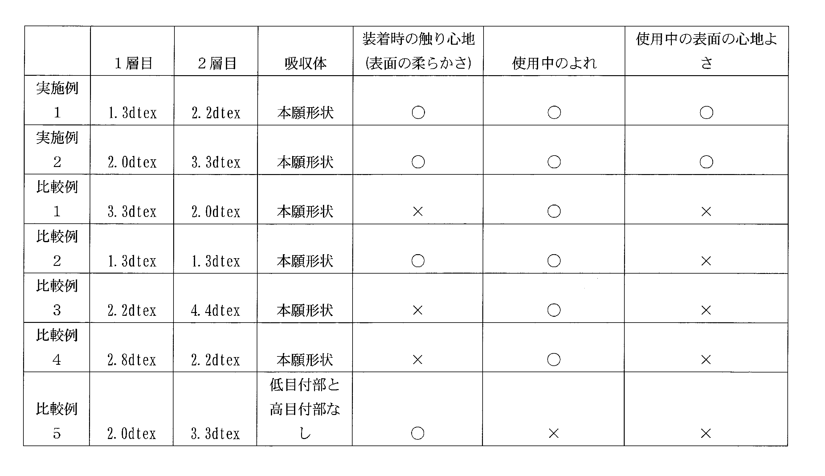
10 :肌面シート
11 :表面シート
111 :第1層
112 :第2層
12 :サイドシート
15 :フラップシート
20 :非肌面シート
30 :吸収体
31 :吸収コア
32 :コアラップ
321 :第1コアラップ
322 :第2コアラップ
41 :第1低目付部
42 :第2低目付部
43 :第3低目付部
45 :高目付部
61 :第1本体粘着部
62 :第2本体粘着部
63 :ウイング粘着部
64 :ヒップフラップ粘着部
81 :前側圧搾部
82 :長手圧搾部
84 :後側圧搾部
L :前後方向
W :幅方向
T :厚み方向
S1 :股下域
S2 :前側域
S3 :後側域
CL :中心線
Claims (9)
- 互いに直交する前後方向及び幅方向と、
着用者の股下に配置される股下域と、
前記股下域の後側に位置する後側域と、
前記股下域と前記後側域に配置される吸収体と、
前記吸収体の肌対向面側に配置される表面シートと、
下着に対して着脱可能に係合する係合部と、を有する吸収性物品であって、
前記吸収体は、吸収材料を有する吸収コアと、前記吸収コアを覆う不織布からなるコアラップと、を有し、
前記表面シートは、不織布からなる第1層と、前記第1層よりも非肌対向面側に配置され、かつ前記第1層よりも径の太い繊維を含む不織布からなる第2層と、を有し、
前記後側域は、圧搾部が配置される圧搾領域と、前記圧搾部が配置されていない非圧搾領域と、を有し、
前記圧搾部は、前記吸収コアと前記表面シートに設けられており、
前記非圧搾領域は、前記幅方向に沿って前記吸収体の一端から他端まで連続的に延びる、吸収性物品。 - 前記後側域の前記吸収コアは、低目付部と、前記低目付部よりも目付が高い高目付部と、を有し、
前記非圧搾領域は、前記低目付部及び前記高目付部に重なる、請求項1に記載の吸収性物品。 - 前記低目付部は、前記幅方向に延びる幅低目付部を有し、
前記幅低目付部は、前記前後方向に間隔を空けて複数配置される、請求項2に記載の吸収性物品。 - 前記低目付部は、前記前後方向に沿って延びる前後低目付部を有し、
前記前後低目付部は、前記非圧搾領域に重なって配置される、請求項2又は請求項3に記載の吸収性物品。 - 前記非圧搾領域の前記前後方向の長さは、30mm以上である、請求項1から請求項4のいずれかに記載の吸収性物品。
- 前記後側域において、前記股下域の前記吸収コアの外側縁よりも幅方向の外側に延びるヒップフラップを有し、
前記非圧搾領域は、前記ヒップフラップの最大幅の位置から前記幅方向に延びる仮想線上に配置される、請求項1から請求項5のいずれかに記載の吸収性物品。 - 前記幅方向における前記ヒップフラップの最大幅の位置は、前記前後方向における前記後側域の中央よりも後側に位置しており、
前記圧搾領域は、前記幅方向における前記ヒップフラップの最大幅の位置よりも後側に配置される、請求項6に記載の吸収性物品。 - 前記第1層を構成する繊維の径は、2.0dtex未満である、請求項1から請求項7のいずれに記載の吸収性物品。
- 前記コアラップの幅方向中央は、前記吸収コアの肌対向面側に配置され、
前記コアラップの展開状態における前記コアラップの外側縁は、前記吸収コアの肌対向面側又は前記吸収コアの外側縁よりも幅方向外側に配置される、請求項1から請求項8のいずれかに記載の吸収性物品。
Priority Applications (2)
| Application Number | Priority Date | Filing Date | Title |
|---|---|---|---|
| CN201680065608.XA CN108348384B (zh) | 2015-11-09 | 2016-08-19 | 吸收性物品 |
| KR1020187016004A KR101964977B1 (ko) | 2015-11-09 | 2016-08-19 | 흡수성 물품 |
Applications Claiming Priority (2)
| Application Number | Priority Date | Filing Date | Title |
|---|---|---|---|
| JP2015219170A JP6411309B2 (ja) | 2015-11-09 | 2015-11-09 | 吸収性物品 |
| JP2015-219170 | 2015-11-09 |
Publications (1)
| Publication Number | Publication Date |
|---|---|
| WO2017081902A1 true WO2017081902A1 (ja) | 2017-05-18 |
Family
ID=58696083
Family Applications (1)
| Application Number | Title | Priority Date | Filing Date |
|---|---|---|---|
| PCT/JP2016/074269 Ceased WO2017081902A1 (ja) | 2015-11-09 | 2016-08-19 | 吸収性物品 |
Country Status (5)
| Country | Link |
|---|---|
| JP (1) | JP6411309B2 (ja) |
| KR (1) | KR101964977B1 (ja) |
| CN (1) | CN108348384B (ja) |
| TW (1) | TWI703967B (ja) |
| WO (1) | WO2017081902A1 (ja) |
Families Citing this family (7)
| Publication number | Priority date | Publication date | Assignee | Title |
|---|---|---|---|---|
| JP6600677B2 (ja) * | 2017-12-28 | 2019-10-30 | ユニ・チャーム株式会社 | パンツ型吸収性物品 |
| CN114099152B (zh) * | 2018-08-14 | 2022-12-02 | 尤妮佳股份有限公司 | 一次性尿布 |
| JP7125310B2 (ja) * | 2018-09-04 | 2022-08-24 | 花王株式会社 | パッド型吸収性物品 |
| JP7055115B2 (ja) * | 2019-06-20 | 2022-04-15 | ユニ・チャーム株式会社 | 吸収性物品 |
| JP2021083542A (ja) * | 2019-11-26 | 2021-06-03 | ユニ・チャーム株式会社 | 吸収性物品 |
| JP7353999B2 (ja) * | 2020-01-31 | 2023-10-02 | ユニ・チャーム株式会社 | 吸収性物品 |
| WO2023277013A1 (ja) * | 2021-06-30 | 2023-01-05 | ユニ・チャーム株式会社 | 吸収性物品 |
Citations (5)
| Publication number | Priority date | Publication date | Assignee | Title |
|---|---|---|---|---|
| JP2002173863A (ja) * | 2000-12-01 | 2002-06-21 | Kao Corp | 吸収性物品の表面シート |
| JP2008245959A (ja) * | 2007-03-30 | 2008-10-16 | Nippon Paper Crecia Co Ltd | 吸収性物品 |
| JP2009261777A (ja) * | 2008-04-28 | 2009-11-12 | Kao Corp | 吸収性物品 |
| JP2012239722A (ja) * | 2011-05-20 | 2012-12-10 | Kao Corp | 吸収性物品 |
| JP2014128551A (ja) * | 2012-11-29 | 2014-07-10 | Kao Corp | 吸収性パッド |
Family Cites Families (9)
| Publication number | Priority date | Publication date | Assignee | Title |
|---|---|---|---|---|
| JP4911830B2 (ja) * | 2001-04-04 | 2012-04-04 | ピジョン株式会社 | 吸収性製品 |
| CN101065085B (zh) | 2004-11-30 | 2011-03-16 | 宝洁公司 | 具有一对后侧翼的吸收制品 |
| JP5649361B2 (ja) * | 2010-08-02 | 2015-01-07 | ユニ・チャーム株式会社 | 吸収性物品 |
| JP5939737B2 (ja) * | 2011-03-02 | 2016-06-22 | ユニ・チャーム株式会社 | 吸収性物品およびその製造方法 |
| JP6141008B2 (ja) * | 2012-07-19 | 2017-06-07 | ユニ・チャーム株式会社 | 吸収性物品 |
| US9707135B2 (en) * | 2013-03-15 | 2017-07-18 | Advanced Absorbent Technologies, Llc | Disposable absorbent article |
| JP5992381B2 (ja) * | 2013-09-04 | 2016-09-14 | 大王製紙株式会社 | 吸収性物品 |
| JP6080262B2 (ja) * | 2013-11-20 | 2017-02-15 | 花王株式会社 | 吸収性物品 |
| CN204274813U (zh) * | 2014-11-07 | 2015-04-22 | 重庆百亚卫生用品有限公司 | 高分子呈线形分布的吸收芯体 |
-
2015
- 2015-11-09 JP JP2015219170A patent/JP6411309B2/ja active Active
-
2016
- 2016-08-19 KR KR1020187016004A patent/KR101964977B1/ko not_active Expired - Fee Related
- 2016-08-19 WO PCT/JP2016/074269 patent/WO2017081902A1/ja not_active Ceased
- 2016-08-19 CN CN201680065608.XA patent/CN108348384B/zh active Active
- 2016-09-08 TW TW105129148A patent/TWI703967B/zh active
Patent Citations (5)
| Publication number | Priority date | Publication date | Assignee | Title |
|---|---|---|---|---|
| JP2002173863A (ja) * | 2000-12-01 | 2002-06-21 | Kao Corp | 吸収性物品の表面シート |
| JP2008245959A (ja) * | 2007-03-30 | 2008-10-16 | Nippon Paper Crecia Co Ltd | 吸収性物品 |
| JP2009261777A (ja) * | 2008-04-28 | 2009-11-12 | Kao Corp | 吸収性物品 |
| JP2012239722A (ja) * | 2011-05-20 | 2012-12-10 | Kao Corp | 吸収性物品 |
| JP2014128551A (ja) * | 2012-11-29 | 2014-07-10 | Kao Corp | 吸収性パッド |
Also Published As
| Publication number | Publication date |
|---|---|
| JP2017086388A (ja) | 2017-05-25 |
| CN108348384B (zh) | 2020-10-09 |
| TWI703967B (zh) | 2020-09-11 |
| JP6411309B2 (ja) | 2018-10-24 |
| TW201722380A (zh) | 2017-07-01 |
| CN108348384A (zh) | 2018-07-31 |
| KR20180084842A (ko) | 2018-07-25 |
| KR101964977B1 (ko) | 2019-04-01 |
Similar Documents
| Publication | Publication Date | Title |
|---|---|---|
| JP6411309B2 (ja) | 吸収性物品 | |
| CN106488757B (zh) | 吸收性物品 | |
| KR101143077B1 (ko) | 음순간 패드 | |
| CN107106350B (zh) | 吸收性物品 | |
| JP5558617B1 (ja) | 吸収性パッド | |
| JP6190861B2 (ja) | 吸収性物品 | |
| CN108472166B (zh) | 吸收性物品 | |
| JP2017060635A (ja) | 女性用吸収性物品 | |
| JP6080935B1 (ja) | 吸収性物品 | |
| JP6353871B2 (ja) | 吸収性物品 | |
| JP2017209521A (ja) | 吸収性物品 | |
| JP5859621B1 (ja) | 吸収性物品 | |
| WO2016051933A1 (ja) | 吸収性物品 | |
| WO2014084087A1 (ja) | 吸収性パッド | |
| JP7445430B2 (ja) | 吸収性物品本体及び吸収性物品 | |
| JP2017060781A (ja) | 吸収性物品 | |
| JP6377482B2 (ja) | 吸収性物品 | |
| JP7724707B2 (ja) | 吸収性物品 | |
| JP6456275B2 (ja) | 吸収性物品 | |
| JP6456276B2 (ja) | 吸収性物品 | |
| JP6456136B2 (ja) | 吸収性物品 | |
| WO2023120694A1 (ja) | 吸収性物品 | |
| WO2015159878A1 (ja) | 吸収性物品 |
Legal Events
| Date | Code | Title | Description |
|---|---|---|---|
| 121 | Ep: the epo has been informed by wipo that ep was designated in this application |
Ref document number: 16863866 Country of ref document: EP Kind code of ref document: A1 |
|
| NENP | Non-entry into the national phase |
Ref country code: DE |
|
| ENP | Entry into the national phase |
Ref document number: 20187016004 Country of ref document: KR Kind code of ref document: A |
|
| WWE | Wipo information: entry into national phase |
Ref document number: 1020187016004 Country of ref document: KR |
|
| 122 | Ep: pct application non-entry in european phase |
Ref document number: 16863866 Country of ref document: EP Kind code of ref document: A1 |