WO2017078131A1 - モールドの洗浄システム - Google Patents
モールドの洗浄システム Download PDFInfo
- Publication number
- WO2017078131A1 WO2017078131A1 PCT/JP2016/082777 JP2016082777W WO2017078131A1 WO 2017078131 A1 WO2017078131 A1 WO 2017078131A1 JP 2016082777 W JP2016082777 W JP 2016082777W WO 2017078131 A1 WO2017078131 A1 WO 2017078131A1
- Authority
- WO
- WIPO (PCT)
- Prior art keywords
- mold
- laser
- molding surface
- cleaning
- laser head
- Prior art date
Links
Images


Classifications
-
- B—PERFORMING OPERATIONS; TRANSPORTING
- B08—CLEANING
- B08B—CLEANING IN GENERAL; PREVENTION OF FOULING IN GENERAL
- B08B7/00—Cleaning by methods not provided for in a single other subclass or a single group in this subclass
- B08B7/0035—Cleaning by methods not provided for in a single other subclass or a single group in this subclass by radiant energy, e.g. UV, laser, light beam or the like
- B08B7/0042—Cleaning by methods not provided for in a single other subclass or a single group in this subclass by radiant energy, e.g. UV, laser, light beam or the like by laser
-
- B—PERFORMING OPERATIONS; TRANSPORTING
- B23—MACHINE TOOLS; METAL-WORKING NOT OTHERWISE PROVIDED FOR
- B23K—SOLDERING OR UNSOLDERING; WELDING; CLADDING OR PLATING BY SOLDERING OR WELDING; CUTTING BY APPLYING HEAT LOCALLY, e.g. FLAME CUTTING; WORKING BY LASER BEAM
- B23K26/00—Working by laser beam, e.g. welding, cutting or boring
- B23K26/02—Positioning or observing the workpiece, e.g. with respect to the point of impact; Aligning, aiming or focusing the laser beam
-
- B—PERFORMING OPERATIONS; TRANSPORTING
- B23—MACHINE TOOLS; METAL-WORKING NOT OTHERWISE PROVIDED FOR
- B23K—SOLDERING OR UNSOLDERING; WELDING; CLADDING OR PLATING BY SOLDERING OR WELDING; CUTTING BY APPLYING HEAT LOCALLY, e.g. FLAME CUTTING; WORKING BY LASER BEAM
- B23K26/00—Working by laser beam, e.g. welding, cutting or boring
- B23K26/352—Working by laser beam, e.g. welding, cutting or boring for surface treatment
-
- B—PERFORMING OPERATIONS; TRANSPORTING
- B29—WORKING OF PLASTICS; WORKING OF SUBSTANCES IN A PLASTIC STATE IN GENERAL
- B29C—SHAPING OR JOINING OF PLASTICS; SHAPING OF MATERIAL IN A PLASTIC STATE, NOT OTHERWISE PROVIDED FOR; AFTER-TREATMENT OF THE SHAPED PRODUCTS, e.g. REPAIRING
- B29C33/00—Moulds or cores; Details thereof or accessories therefor
- B29C33/70—Maintenance
- B29C33/72—Cleaning
-
- B—PERFORMING OPERATIONS; TRANSPORTING
- B29—WORKING OF PLASTICS; WORKING OF SUBSTANCES IN A PLASTIC STATE IN GENERAL
- B29D—PRODUCING PARTICULAR ARTICLES FROM PLASTICS OR FROM SUBSTANCES IN A PLASTIC STATE
- B29D30/00—Producing pneumatic or solid tyres or parts thereof
- B29D30/0061—Accessories, details or auxiliary operations not otherwise provided for
-
- B—PERFORMING OPERATIONS; TRANSPORTING
- B29—WORKING OF PLASTICS; WORKING OF SUBSTANCES IN A PLASTIC STATE IN GENERAL
- B29D—PRODUCING PARTICULAR ARTICLES FROM PLASTICS OR FROM SUBSTANCES IN A PLASTIC STATE
- B29D30/00—Producing pneumatic or solid tyres or parts thereof
- B29D30/06—Pneumatic tyres or parts thereof (e.g. produced by casting, moulding, compression moulding, injection moulding, centrifugal casting)
- B29D30/0601—Vulcanising tyres; Vulcanising presses for tyres
- B29D30/0662—Accessories, details or auxiliary operations
-
- G—PHYSICS
- G05—CONTROLLING; REGULATING
- G05D—SYSTEMS FOR CONTROLLING OR REGULATING NON-ELECTRIC VARIABLES
- G05D3/00—Control of position or direction
- G05D3/12—Control of position or direction using feedback
-
- B—PERFORMING OPERATIONS; TRANSPORTING
- B29—WORKING OF PLASTICS; WORKING OF SUBSTANCES IN A PLASTIC STATE IN GENERAL
- B29C—SHAPING OR JOINING OF PLASTICS; SHAPING OF MATERIAL IN A PLASTIC STATE, NOT OTHERWISE PROVIDED FOR; AFTER-TREATMENT OF THE SHAPED PRODUCTS, e.g. REPAIRING
- B29C33/00—Moulds or cores; Details thereof or accessories therefor
- B29C33/70—Maintenance
- B29C2033/705—Mould inspection means, e.g. cameras
-
- B—PERFORMING OPERATIONS; TRANSPORTING
- B29—WORKING OF PLASTICS; WORKING OF SUBSTANCES IN A PLASTIC STATE IN GENERAL
- B29D—PRODUCING PARTICULAR ARTICLES FROM PLASTICS OR FROM SUBSTANCES IN A PLASTIC STATE
- B29D30/00—Producing pneumatic or solid tyres or parts thereof
- B29D30/0061—Accessories, details or auxiliary operations not otherwise provided for
- B29D2030/0083—Attaching monitoring devices to tyres before or after vulcanization by inserting them inside tyre cavities
-
- B—PERFORMING OPERATIONS; TRANSPORTING
- B29—WORKING OF PLASTICS; WORKING OF SUBSTANCES IN A PLASTIC STATE IN GENERAL
- B29D—PRODUCING PARTICULAR ARTICLES FROM PLASTICS OR FROM SUBSTANCES IN A PLASTIC STATE
- B29D30/00—Producing pneumatic or solid tyres or parts thereof
- B29D30/06—Pneumatic tyres or parts thereof (e.g. produced by casting, moulding, compression moulding, injection moulding, centrifugal casting)
- B29D30/0601—Vulcanising tyres; Vulcanising presses for tyres
- B29D30/0662—Accessories, details or auxiliary operations
- B29D2030/0663—Mould maintenance, e.g. cleaning, washing, repairing
-
- B—PERFORMING OPERATIONS; TRANSPORTING
- B29—WORKING OF PLASTICS; WORKING OF SUBSTANCES IN A PLASTIC STATE IN GENERAL
- B29K—INDEXING SCHEME ASSOCIATED WITH SUBCLASSES B29B, B29C OR B29D, RELATING TO MOULDING MATERIALS OR TO MATERIALS FOR MOULDS, REINFORCEMENTS, FILLERS OR PREFORMED PARTS, e.g. INSERTS
- B29K2021/00—Use of unspecified rubbers as moulding material
-
- B—PERFORMING OPERATIONS; TRANSPORTING
- B29—WORKING OF PLASTICS; WORKING OF SUBSTANCES IN A PLASTIC STATE IN GENERAL
- B29L—INDEXING SCHEME ASSOCIATED WITH SUBCLASS B29C, RELATING TO PARTICULAR ARTICLES
- B29L2030/00—Pneumatic or solid tyres or parts thereof
Definitions
- the present invention relates to a mold cleaning system, and more particularly, to a mold that can efficiently remove dirt while preventing damage to a molding surface, even if the molding has a molding surface having a complicated shape. It relates to a cleaning system.
- the molding surface for vulcanizing rubber products such as tires is slightly contaminated with rubber components and compounding agents every time it is vulcanized. This dirt gradually accumulates by repeated use of the mold. If the dirt is left as it is, the quality of the vulcanized product is adversely affected. For this reason, it is necessary to clean the molding surface and remove the dirt as appropriate.
- Known methods for cleaning the mold include a shot blast cleaning method, a laser beam cleaning method, a plasma cleaning method, and the like.
- the molding surface is easily damaged.
- a laser beam cleaning method that irradiates the molding surface with laser light and removes dirt by the shock wave
- a plasma cleaning method in which dirt is removed by chemically reacting with the plasma is desirable.
- the plasma cleaning method has a small area that can be cleaned per unit time, the laser beam cleaning method is more preferable in consideration of efficiency.
- Patent Documents 1 and 2 Various mold cleaning methods using laser light have been proposed (see, for example, Patent Documents 1 and 2).
- laser light (CO 2 laser light) supplied from a laser oscillator is irradiated from a laser head onto a molding surface of a mold to remove dirt.
- the arm (manipulator) for moving the laser head is controlled by the original shape data (cad data, etc.) of the mold and the position correcting means of the laser head, and moves the laser head along the unevenness of the molding surface (patent) (Refer to paragraphs 0011 and 0021 to 0025 of Document 1).
- the molding surface of the mold is not necessarily formed in the same shape, and is formed in various shapes. Therefore, in the method described in Patent Document 1, in order to clean a mold having a different molding surface, it is necessary to call the original shape data of the mold stored in the control device every time the mold is cleaned. become. In the case of a tire vulcanization mold that has a huge number of molding surface shapes, it is necessary to confirm that the mold to be cleaned corresponds to the original shape data each time it is cleaned, which makes the work complicated. There's a problem.
- the laser irradiator is fixed at a predetermined position, and the mold is moved so that the mold surface is tilted from a posture perpendicular to the optical axis of the laser beam. Rotate. In order to rotate the mold in this way, a process such as teaching this movement in advance is required.
- An object of the present invention is to provide a mold cleaning system capable of efficiently removing dirt while preventing damage to a molding surface, even if the mold has a molding surface having a complicated shape. .
- a mold cleaning system of the present invention includes a laser oscillator, a laser head that irradiates a molding surface of the mold with laser light supplied from the laser oscillator, and the laser head that freely moves in three dimensions.
- a mold cleaning system comprising an arm and a control device for controlling the movement of the arm, a camera for obtaining three-dimensional image data of a molding surface of the mold to be cleaned is provided, and the camera is used for cleaning the mold.
- the laser head is moved along the molding surface, and the molding surface is cleaned by irradiating a laser beam.
- Another mold cleaning system of the present invention includes a laser oscillator, a laser head that irradiates a molding surface of the mold with laser light supplied from the laser oscillator, an arm that freely moves the laser head in three dimensions,
- a mold cleaning system comprising a control device for controlling the movement of an arm, a camera for acquiring three-dimensional image data of a molding surface of a mold to be cleaned is provided, and the camera acquired by the camera when cleaning the mold
- the laser head is moved along the molding surface, the laser beam is irradiated to clean the molding surface, and the laser head has a laser irradiation width.
- Is equipped with a variable laser head and an appropriate laser irradiation width is preset for each part to be cleaned. Characterized in that the setting to perform and cleansed in order set the laser irradiation width.
- the mold when the mold is cleaned, three-dimensional image data of the molding surface of the mold to be cleaned is acquired by the camera. Therefore, the shape of the molding surface of the mold at the time of cleaning can be accurately grasped. Therefore, it is not necessary to manually perform the operation of calling the shape data of the molding surface of the mold to be cleaned from the database each time it is cleaned and confirming the correspondence between the actual mold and the shape data. Then, based on the acquired image data, the laser head is moved along the molding surface, and the molding surface is cleaned by irradiating the laser beam. Therefore, even a mold having a molding surface with a complicated shape is used. Thus, it is possible to efficiently remove dirt while preventing damage to the molding surface without manpower.
- the image data of the molding surface at the time of cleaning is acquired, so it is dirty compared to the case where the shape data of the molding surface stored in advance is used. It is advantageous to clean cleanly without leaving.
- a relatively small laser head can be used without interfering with the mold or the like.
- the laser head can be arranged at an optimum position.
- laser light can be irradiated evenly on even a complicated shape portion, which is advantageous for removing dirt cleanly.
- a specific portion can be cleaned roughly using a relatively large laser head and, in addition, can be cleaned using a relatively small laser head. Since the laser irradiation width can be increased if a relatively large laser head is used, it is possible to reduce the cleaning time and perform efficient cleaning.
- the laser irradiation width is relatively set, for example, for a portion where unevenness has entered a narrow range of the molding surface. Make small and clean. Thereby, even a complicated shape portion can be irradiated with laser light without unevenness, which is advantageous in removing dirt cleanly. Further, it is possible to irradiate the laser beam only on the intended range, and the laser beam is not irradiated on the unintended range. On the other hand, a relatively flat and wide part is cleaned with a relatively large laser irradiation width. Thereby, the required range can be cleaned in a short time.
- the cleaning state of the molding surface is grasped, and the grasped cleaning state and the position information of the molding surface are obtained.
- Store in the control device and set the setting so that cleaning is performed by irradiating the laser light from the laser head again to the position of the molding surface where the grasped cleaning state does not satisfy the preset standard. You can also. With this setting, only the dirty position (range) is re-washed later, which is advantageous for removing the dirt efficiently and cleanly.
- a temperature sensor that sequentially detects the temperature of the molding surface irradiated with the laser light is provided, and the laser light irradiation is interrupted when the temperature detected by the temperature sensor exceeds a preset allowable temperature. It can also be set to. In the case of this setting, it can be avoided that the molding surface is excessively heated by the irradiated laser light. That is, it is possible to prevent a problem that the molding surface is thermally deformed by the laser beam.
- Studless tire vulcanization molds have a complex molding surface, and pneumatic tire vulcanization casting molds have minute gaps formed on the molding surface. Dirt can be removed efficiently while preventing damage.
- FIG. 1 is an explanatory view illustrating the mold cleaning system of the present invention in plan view.
- FIG. 2 is an explanatory view illustrating the molding surface of the studless tire vulcanization mold in plan view.
- FIG. 3 is an explanatory view illustrating the molding surface of the cast-in-mold with an enlarged cross-sectional view.
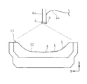
- FIG. 4 is an explanatory view illustrating the camera and the mold to be cleaned in a front view.
- FIG. 5 is an explanatory view illustrating the camera and the mold to be cleaned in a side view.
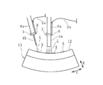
- FIG. 6 is an explanatory view illustrating the laser head and the mold to be cleaned in a side view.
- FIG. 7 is an explanatory view illustrating the laser head and the mold to be cleaned in a front view.
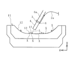
- FIG. 8 is an explanatory view illustrating, in front view, a state in which a laser beam is radiated to a complicated shape portion of the molding surface of the mold using another embodiment of the cleaning system.
- FIG. 9 is an explanatory view illustrating, in front view, a state in which laser light is irradiated onto a relatively flat and wide portion of the molding surface of the mold using the cleaning system of FIG.
- the tire vulcanization mold is targeted for cleaning, but the present invention is not limited to tires and can be used for cleaning molds for vulcanizing rubber products.
- a mold cleaning system 1 of the present invention illustrated in FIG. 1 includes a laser oscillator 2, a laser head 4, an arm 6 to which the laser head 4 is attached, a control device 7 that controls the movement of the arm 6, a camera 3, and the like. It has.
- the camera 3 acquires three-dimensional image data of the molding surface 12 of the mold 11.
- a temperature sensor 8 that sequentially detects the temperature of the molding surface 12 irradiated with the laser beam L is provided.
- the camera 3 and the temperature sensor 8 are attached to the tip of the arm 6, and the image data acquired by the camera 3 and the temperature data detected by the temperature sensor 8 are input to the control device 7.
- the main components of the cleaning system 1 except for the laser oscillator 2 are arranged inside a cleaning booth 9 that is a closed space.
- the cleaning booth 9 is provided with an entrance door 9a and an exit door 9b. When the entrance door 9a and the exit door 9b are closed, the cleaning booth 9 becomes a closed space and can shield the laser beam L.
- a carry-in conveyor device 10a is connected to the entrance door 9a, and a carry-out conveyor device 10c is connected to the exit door 9b.
- the space between the carry-in conveyor device 10a and the carry-out conveyor device 10c is an internal space of the washing booth 9, and the processing conveyor device 10b is disposed at this position.
- the processing conveyor device 10b extends in a circular arc shape.
- the mold 11 to be cleaned is placed on the carry-in conveyor device 10a, and the washed mold 11 is placed on the carry-out conveyor device 10c.
- the processing conveyor device 10b functions as a processing table when the mold 11 is cleaned.
- the laser oscillator 2 and the laser head 4 are connected by an optical fiber cable 2a.
- the laser light L supplied by the laser oscillator 2 is sent to the laser head 4 through the optical fiber cable 2a.
- the laser beam L used in the present invention is preferably a YAG laser beam.
- Laser beam L is applied to the molding surface 12 of the mold 11 by the laser head 4.
- the arm 6 is rotatably attached to the arm base 5 and is configured by connecting a plurality of arm portions 6a and 6b in a freely rotatable manner.
- the laser head 4 is detachably attached to the tip of the arm 6. Therefore, the laser head 4 can be freely moved in three dimensions by controlling the movement of the arm 6.
- a plurality of laser heads 4a and 4b having different head sizes (volumes) are provided.
- One is a relatively large laser head 4a and the other is a relatively small laser head 4b.
- the relatively large laser head 4a has a larger laser irradiation width than the relatively small laser head 4b.
- the relatively large laser head 4a has a built-in galvanometer mirror and is configured to scan the laser beam L in the width direction and irradiate with a wide width.
- the laser irradiation width is, for example, about 4 mm to 70 mm.
- the relatively small laser head 4b irradiates the laser beam L at a pinpoint.
- the oscillation frequency of the laser oscillator 2 is, for example, 10 kHz or more and 40 kHz or less.
- the frequency at which the laser beam L is scanned in the width direction from the laser head 4a is, for example, 20 Hz to 150 Hz.
- the laser irradiation width of each laser head 4a, 4b can be made constant (fixed to a predetermined width). Alternatively, the specification can be made such that the laser irradiation width of one of the laser heads 4a and 4b is variable, or the specification can be made such that the laser irradiation width of each laser head 4a and 4b is variable.
- the mold 11 to be cleaned is not only a normal type mold but also, for example, a studless tire vulcanization mold shown in FIG.
- a groove forming protrusion 13 and a sipe forming protrusion 14 are projected from a forming surface 12.
- the groove forming protrusion 13 is integrally cast with the base material of the mold 11, and the sipe forming protrusion 14 is attached to the forming surface 12 as a separate body.
- the material of the base material of the mold 11 is mainly aluminum, and the material of the sipe molding protrusion 14 is steel.
- the thickness of the sipe molding protrusion 14 is about 0.4 mm or more and 1.2 mm or less.
- the groove forming protrusion 13 may become thin due to the tread pattern of the tire, for example, in the case of a complicated tread pattern. For this reason, the sipe molding projection 14 and the thin groove molding projection 13 are easily damaged during mold cleaning. 2, 4 to 9 indicate the circumferential direction, the radial direction, and the width direction of the tire that is inserted into the mold 11 and vulcanized, respectively.
- molds 11 to be cleaned include, for example, a cast joint mold for pneumatic tire vulcanization shown in FIG.
- the mold 11 is manufactured by a so-called cast joint in which the second casting part 16 is cast after the first casting part 15 is cast.
- a minute gap g is formed in the joint portion M between the first cast portion 15 and the second cast portion 16 by solidification shrinkage of the cast molten metal.
- the size of the minute gap g is, for example, 5 ⁇ m to 80 ⁇ m.
- An exhaust hole 17 is formed in communication with the minute gap g. In this mold 11, unnecessary air and gas at the time of tire vulcanization are discharged from the molding surface 12 through the minute gap g to the exhaust hole 17, and are discharged to the outside of the mold 11 through the exhaust hole 17.
- the minute gap g becomes a portion that is easily damaged during mold cleaning.
- the mold 11 to be cleaned is placed on the carry-in conveyor device 10a.
- the entrance door 9a is opened, and the carry-in conveyor device 10a and the processing conveyor device 10b are moved to move the mold 11 to be cleaned onto the processing conveyor device 10b and positioned at a predetermined position. Thereafter, the entrance door 9a is closed to make the cleaning booth 9 a closed space. If the cleaning booth 9 does not become a closed space, the laser oscillator 2 does not operate.
- the camera 3 is placed at an appropriate position, and three-dimensional image data of the molding surface 12 of the mold 11 is acquired.
- one camera 3 is moved to a desired position (an upper position, a side position, etc. of the molding surface 12) by the arm 6 and the shape data of the molding surface 12 is acquired.
- a plurality of cameras 3 can be provided, and three-dimensional image data of the molding surface 12 can be obtained by imaging the plane shape data and the side surface shape data of the molding surface 12 with the plurality of fixed cameras 3, respectively.
- the movement of the arm 6 is controlled based on the acquired three-dimensional image data (shape data) of the molding surface 12 of the mold 11, and the laser head 4 is formed on the molding surface as illustrated in FIGS. 6 and 7. 12 is moved.
- the laser beam L supplied from the laser oscillator 2 is irradiated onto the molding surface 12 while moving the laser head 4 in this way.
- the dirt X adhering to the molding surface 12 is removed and cleaned by the irradiated laser light L.
- the moving direction of the laser head 4 and the laser are maintained while keeping the distance between the tip of the laser head 4 and the molding surface 12 facing this as constant as possible.
- the irradiation direction of the light L is controlled.
- the moving speed of the laser head 4 is set to a constant speed as much as possible so as to cover the cleaning target range.
- the cleaning system 1 can have a specification having a plurality of arms 6 or a specification having a single arm 6.
- the two laser heads 4 a and 4 b are used together to irradiate the laser beam L because the two arms 6 that operate independently are used.
- the other laser head 4 can be used after one of the laser heads 4 is used. For example, after moving the relatively large laser head 4a so as to cover the cleaning target range and irradiating the laser beam L having a relatively large laser irradiation width, the laser beam L is used by using the relatively small laser head 4b. Irradiate.
- the shape data of the molding surface 12 of the mold 11 to be cleaned is called every time the cleaning is performed. There is no need for manual work to check the correspondence.
- the laser beam L is irradiated while moving the laser head 4 along the molding surface 12 based on the acquired image data, a studless tire vulcanizing mold or a pneumatic tire vulcanizing cast mold is used. Even with the mold 11 having the molding surface 12 having such a complicated shape, it is possible to efficiently remove the dirt X while preventing damage to the molding surface 12 without manpower.
- the image data of the molding surface 12 at the time of cleaning is acquired, and this image data is used for the movement of the laser head 4. Compared to the case where the shape data of the surface 12 is used, it is advantageous to clean cleanly without leaving dirt.
- the image data of the cleaned molding surface 12 is acquired again by the camera 3, and the cleaning state of the molding surface 12 is grasped based on the acquired image data.
- the grasped cleaning state and the position information of the molding surface are stored in the control device 7.
- the laser head 4 After irradiating the entire area of the molding surface 12 with the laser beam L, the laser head 4 is moved again to the position of the molding surface 12 whose grasped cleaning state does not satisfy the preset standard. Then, the laser beam L is irradiated for cleaning.
- control device 7 determines whether or not the grasped cleaning state satisfies a preset standard.
- the reference for determining the cleaning state is set based on, for example, the color density of the image data of the molding surface 12 acquired by the camera 3. If the density is above a certain level, it is set that the stain X remains. Alternatively, it is also possible to acquire image data of the molding surface 12 immediately before and after the irradiation with the laser light L, compare both the image data, and set a reference based on a change in color shading. When the color density is not changed or the degree of change is small, it is set that the stain X remains. With such a setting, only the dirty position (range) is re-washed later, which is advantageous for efficiently removing the dirt X.
- a specific part is inputted and set in the control device 7 in advance, and a relatively small laser head 4b or a relatively large laser head 4a is used for the set specific part.
- cleaning can be performed using a relatively small laser head 4b.
- the specific portion for example, a range of a complicated shape such as a root peripheral range of the sipe forming protrusion 14 illustrated in FIG. 2 or an inner peripheral surface of the minute gap g of the cast joint M illustrated in FIG.
- the laser head 4b can be moved without interfering with the mold 11 or the like by using a relatively small laser head 4b for a specific portion where irregularities are complicatedly entered into a narrow range of the molding surface 12. It can be arranged at an optimal position. Along with this, the laser beam L can be irradiated evenly on the complicatedly shaped portion, which is advantageous for removing dirt cleanly. Alternatively, it is possible to roughly clean the specific part using the relatively large laser head 4a and, in addition, to clean using the relatively small laser head 4b. If the laser head 4a is relatively large, the laser irradiation width can be increased as compared with the relatively small laser head 4b. Therefore, it is possible to shorten the cleaning time and perform cleaning efficiently.
- the temperature of the molding surface 12 irradiated with the laser light L can be sequentially detected by the temperature sensor 8.
- An allowable temperature is previously input and set in the control device 7. This allowable temperature is set to a predetermined temperature that is less than the melting temperature of the mold 11.
- the temperature detected by the temperature sensor 8 exceeds a preset allowable temperature, the irradiation with the laser light L is interrupted. For example, even if there is a problem that the moving speed of the laser head 4 is slowed or stopped due to an unintended factor, if this setting is made, the molding surface 12 is heated excessively by the irradiated laser light L. It will not be done. That is, it is possible to prevent a problem that the molding surface 12 is thermally deformed or damaged by the laser beam L.
- the exit door 9b is opened and the processing conveyor belt 10b and the carry-out conveyor belt 10c are operated to move the mold 11 that has been cleaned from the inside of the cleaning booth 9 to the outside.
- the entrance door 9a is opened, the carry-in conveyor belt 10a is operated, and the mold 11 to be cleaned next is moved from the outside to the inside of the cleaning booth 9, and positioned at a predetermined position on the processing conveyor 10b. In this manner, the mold 11 is sequentially and continuously cleaned.
- one laser head 4 is provided.
- the laser head 4 has a variable laser irradiation width.
- An appropriate laser irradiation width is preset and inputted to the control device 7 for each part to be cleaned. For example, a relatively small laser irradiation width is set for a portion where irregularities are intruded into a narrow range of the molding surface 12, and a relatively large laser irradiation width is set for a relatively flat and wide portion. Is set.
- the portion where the unevenness enters the narrow range of the molding surface 12 is cleaned by irradiating the laser beam L with a relatively small laser irradiation width. Therefore, even in a complicated shape portion, the laser beam L can be irradiated evenly, which is advantageous for removing dirt X cleanly. Further, since the laser beam L can be irradiated only to the intended range, and the laser beam L is not irradiated to the unintended range, the mold 11 is irradiated with the laser beam L to the range where the laser beam L is not necessary. It is possible to avoid the problem of hurting.
- the relatively flat and wide part is cleaned by switching the laser irradiation width and irradiating the laser beam L with a relatively large laser irradiation width.
- the required range can be cleaned in a short time.
Landscapes
- Engineering & Computer Science (AREA)
- Physics & Mathematics (AREA)
- Optics & Photonics (AREA)
- Mechanical Engineering (AREA)
- Plasma & Fusion (AREA)
- General Physics & Mathematics (AREA)
- Automation & Control Theory (AREA)
- Moulds For Moulding Plastics Or The Like (AREA)
- Laser Beam Processing (AREA)
Abstract
Description
2 レーザ発振器
2a 光ファイバーケーブル
3 カメラ
4、4a、4b レーザヘッド
5 アームベース
6 アーム
6a、6b アーム部
7 制御装置
8 温度センサ
9 洗浄ブース
9a 入口扉
9b 出口扉
10a 搬入用コンベヤ装置
10b 処理用コンベヤ装置(処理台)
10c 搬出用コンベヤ装置
11 モールド
12 成形面
13 溝成形突起
14 サイプ成形突起
15 第1鋳造部
16 第2鋳造部
17 排気穴
M 鋳継ぎ部
L レーザ光
X 汚れ
g 微小すき間
Claims (5)
- レーザ発振器と、このレーザ発振器から供給されるレーザ光をモールドの成形面に照射するレーザヘッドと、このレーザヘッドを3次元に自在移動させるアームと、このアームの動きを制御する制御装置とを備えたモールドの洗浄システムにおいて、
洗浄するモールドの成形面の3次元の画像データを取得するカメラを設け、モールドを洗浄する際に前記カメラにより取得された前記画像データに基づいて前記アームの動きを制御することにより、前記レーザヘッドをその成形面に沿って移動させつつ、レーザ光を照射してその成形面を洗浄し、前記レーザヘッドとして、ヘッドの大きさが異なる複数のレーザヘッドを備え、予め設定されている特定の部位に対しては、相対的に小さいレーザヘッドを用いて、または、相対的に大きいレーザヘッドに加えて相対的に小さいレーザヘッドを用いて洗浄を行う設定にしたことを特徴とするモールドの洗浄システム。 - レーザ発振器と、このレーザ発振器から供給されるレーザ光をモールドの成形面に照射するレーザヘッドと、このレーザヘッドを3次元に自在移動させるアームと、このアームの動きを制御する制御装置とを備えたモールドの洗浄システムにおいて、
洗浄するモールドの成形面の3次元の画像データを取得するカメラを設け、モールドを洗浄する際に前記カメラにより取得された前記画像データに基づいて前記アームの動きを制御することにより、前記レーザヘッドをその成形面に沿って移動させつつ、レーザ光を照射してその成形面を洗浄し、前記レーザヘッドとして、レーザ照射幅が可変のレーザヘッドを備え、洗浄する部位毎に適切なレーザ照射幅を予め設定し、それぞれの洗浄する部位を予め設定されたレーザ照射幅にして洗浄を行う設定にしたことを特徴とするモールドの洗浄システム。 - 前記カメラにより取得された洗浄後のモールドの成形面の3次元の画像データに基づいてその成形面の洗浄状態を把握し、この把握した洗浄状態およびその成形面の位置情報を前記制御装置に記憶し、前記把握した洗浄状態が予め設定されている基準に満たない成形面の位置に対して、再度、前記レーザヘッドから前記レーザ光を照射して洗浄を行なう設定にした請求項1または2に記載のモールドの洗浄システム。
- 前記レーザ光が照射されている前記成形面の温度を逐次検知する温度センサを備え、この温度センサによる検知温度が予め設定されている許容温度を超えた場合には、前記レーザ光の照射を中断する設定にした請求項1~3のいずれかに記載のモールドの洗浄システム。
- 前記モールドがスタッドレスタイヤ加硫用モールドまたは空気入りタイヤ加硫用鋳継ぎモールドである請求項1~4のいずれかに記載のモールドの洗浄システム。
Priority Applications (5)
| Application Number | Priority Date | Filing Date | Title |
|---|---|---|---|
| CN201680059095.1A CN108136627B (zh) | 2015-11-05 | 2016-11-04 | 模具的清洗系统 |
| US15/773,155 US10471632B2 (en) | 2015-11-05 | 2016-11-04 | Mold cleaning system |
| JP2016566833A JP6260720B2 (ja) | 2015-11-05 | 2016-11-04 | モールドの洗浄システム |
| KR1020187009803A KR101868363B1 (ko) | 2015-11-05 | 2016-11-04 | 몰드의 세정 시스템 |
| EP16862191.0A EP3372370B1 (en) | 2015-11-05 | 2016-11-04 | Mold cleaning system |
Applications Claiming Priority (2)
| Application Number | Priority Date | Filing Date | Title |
|---|---|---|---|
| JP2015-217218 | 2015-11-05 | ||
| JP2015217218 | 2015-11-05 |
Publications (1)
| Publication Number | Publication Date |
|---|---|
| WO2017078131A1 true WO2017078131A1 (ja) | 2017-05-11 |
Family
ID=58662073
Family Applications (1)
| Application Number | Title | Priority Date | Filing Date |
|---|---|---|---|
| PCT/JP2016/082777 WO2017078131A1 (ja) | 2015-11-05 | 2016-11-04 | モールドの洗浄システム |
Country Status (6)
| Country | Link |
|---|---|
| US (1) | US10471632B2 (ja) |
| EP (1) | EP3372370B1 (ja) |
| JP (1) | JP6260720B2 (ja) |
| KR (1) | KR101868363B1 (ja) |
| CN (1) | CN108136627B (ja) |
| WO (1) | WO2017078131A1 (ja) |
Cited By (4)
| Publication number | Priority date | Publication date | Assignee | Title |
|---|---|---|---|---|
| WO2019155715A1 (ja) * | 2018-02-09 | 2019-08-15 | 横浜ゴム株式会社 | 加硫用モールドの洗浄装置および方法 |
| JP2020168795A (ja) * | 2019-04-03 | 2020-10-15 | 住友ゴム工業株式会社 | 金型面のレーザ洗浄方法 |
| EP3814029A4 (en) * | 2018-05-08 | 2022-01-26 | Automation Innovation Pty Ltd | LASER CLEANING SYSTEM |
| WO2023188339A1 (ja) * | 2022-03-31 | 2023-10-05 | 將 北川 | 金型洗浄方法と金型洗浄装置 |
Families Citing this family (4)
| Publication number | Priority date | Publication date | Assignee | Title |
|---|---|---|---|---|
| JP2020006600A (ja) * | 2018-07-10 | 2020-01-16 | Towa株式会社 | 成形型クリーニング装置及び方法、樹脂成形装置、並びに樹脂成形品製造方法 |
| CN110744208A (zh) * | 2018-07-23 | 2020-02-04 | 杭州纤纳光电科技有限公司 | 产线激光划线设备及其使用方法 |
| US11982630B2 (en) * | 2020-04-29 | 2024-05-14 | DataGarden, Inc. | Method and apparatus for cleanliness determination of areas and objects via video monitoring |
| CN113232210B (zh) * | 2021-04-29 | 2023-07-14 | 安徽省江海橡塑制品有限责任公司 | 一种止水橡胶制备用硫化装置 |
Citations (4)
| Publication number | Priority date | Publication date | Assignee | Title |
|---|---|---|---|---|
| US6369353B1 (en) * | 1998-02-20 | 2002-04-09 | The Goodyear Tire & Rubber Company | Robotic laser tire mold cleaning system and method of use |
| JP2005205833A (ja) * | 2004-01-26 | 2005-08-04 | Sumitomo Heavy Ind Ltd | 金型クリーニング装置 |
| JP2005532170A (ja) * | 2002-07-11 | 2005-10-27 | コミツサリア タ レネルジー アトミーク | レーザーを使用して対象物を機械加工するためのシステムおよび方法 |
| WO2015199113A1 (ja) * | 2014-06-26 | 2015-12-30 | 横浜ゴム株式会社 | モールドの洗浄システム |
Family Cites Families (9)
| Publication number | Priority date | Publication date | Assignee | Title |
|---|---|---|---|---|
| US5373140A (en) * | 1993-03-16 | 1994-12-13 | Vernay Laboratories, Inc. | System for cleaning molding equipment using a laser |
| DE19517218C1 (de) * | 1995-05-11 | 1996-07-18 | Uniroyal Englebert Gmbh | Verfahren und Vorrichtung zum Reinigen von Vulkanisationsformen |
| IT1282722B1 (it) * | 1996-03-01 | 1998-03-31 | Pirelli | Metodo ed apparato per la pulitura di stampi di vulcanizzazione di articoli in materiale elastomerico |
| JPH1199524A (ja) * | 1997-09-29 | 1999-04-13 | Fuji Industries:Kk | 金型クリーニング装置 |
| WO1999042228A1 (en) * | 1998-02-20 | 1999-08-26 | The Goodyear Tire & Rubber Company | Robotic laser tire mold cleaning system and method of use |
| JP2004018239A (ja) | 2002-06-20 | 2004-01-22 | Towa Corp | 保管方法及び保管装置 |
| JP2004167744A (ja) | 2002-11-18 | 2004-06-17 | Toyo Tire & Rubber Co Ltd | 金型洗浄方法及び洗浄装置 |
| JP2008062633A (ja) | 2006-08-09 | 2008-03-21 | Tosei Electro Beam Kk | レーザ加工を用いた金型などの洗浄方法及び洗浄装置並びにタイヤ成形金型の洗浄装置 |
| JP2010044030A (ja) * | 2008-08-18 | 2010-02-25 | Fujitsu Ltd | レーザクリーニング装置およびレーザクリーニング方法 |
-
2016
- 2016-11-04 EP EP16862191.0A patent/EP3372370B1/en active Active
- 2016-11-04 WO PCT/JP2016/082777 patent/WO2017078131A1/ja active Application Filing
- 2016-11-04 KR KR1020187009803A patent/KR101868363B1/ko active IP Right Grant
- 2016-11-04 JP JP2016566833A patent/JP6260720B2/ja active Active
- 2016-11-04 US US15/773,155 patent/US10471632B2/en active Active
- 2016-11-04 CN CN201680059095.1A patent/CN108136627B/zh active Active
Patent Citations (4)
| Publication number | Priority date | Publication date | Assignee | Title |
|---|---|---|---|---|
| US6369353B1 (en) * | 1998-02-20 | 2002-04-09 | The Goodyear Tire & Rubber Company | Robotic laser tire mold cleaning system and method of use |
| JP2005532170A (ja) * | 2002-07-11 | 2005-10-27 | コミツサリア タ レネルジー アトミーク | レーザーを使用して対象物を機械加工するためのシステムおよび方法 |
| JP2005205833A (ja) * | 2004-01-26 | 2005-08-04 | Sumitomo Heavy Ind Ltd | 金型クリーニング装置 |
| WO2015199113A1 (ja) * | 2014-06-26 | 2015-12-30 | 横浜ゴム株式会社 | モールドの洗浄システム |
Non-Patent Citations (1)
| Title |
|---|
| See also references of EP3372370A4 * |
Cited By (8)
| Publication number | Priority date | Publication date | Assignee | Title |
|---|---|---|---|---|
| WO2019155715A1 (ja) * | 2018-02-09 | 2019-08-15 | 横浜ゴム株式会社 | 加硫用モールドの洗浄装置および方法 |
| JP2019136937A (ja) * | 2018-02-09 | 2019-08-22 | 横浜ゴム株式会社 | 加硫用モールドの洗浄装置および方法 |
| EP3750680A4 (en) * | 2018-02-09 | 2021-11-03 | The Yokohama Rubber Co., Ltd. | VULCANIZATION MOLD CLEANING DEVICE AND METHOD |
| US11897218B2 (en) | 2018-02-09 | 2024-02-13 | The Yokohama Rubber Co., Ltd. | Cleaning device and method for cleaning vulcanization mold |
| EP3814029A4 (en) * | 2018-05-08 | 2022-01-26 | Automation Innovation Pty Ltd | LASER CLEANING SYSTEM |
| JP2020168795A (ja) * | 2019-04-03 | 2020-10-15 | 住友ゴム工業株式会社 | 金型面のレーザ洗浄方法 |
| JP7238555B2 (ja) | 2019-04-03 | 2023-03-14 | 住友ゴム工業株式会社 | 金型面のレーザ洗浄方法 |
| WO2023188339A1 (ja) * | 2022-03-31 | 2023-10-05 | 將 北川 | 金型洗浄方法と金型洗浄装置 |
Also Published As
| Publication number | Publication date |
|---|---|
| EP3372370A1 (en) | 2018-09-12 |
| KR101868363B1 (ko) | 2018-06-18 |
| US10471632B2 (en) | 2019-11-12 |
| JP6260720B2 (ja) | 2018-01-17 |
| KR20180043372A (ko) | 2018-04-27 |
| CN108136627B (zh) | 2019-06-14 |
| EP3372370A4 (en) | 2019-08-14 |
| EP3372370B1 (en) | 2021-09-08 |
| JPWO2017078131A1 (ja) | 2017-11-02 |
| US20180319045A1 (en) | 2018-11-08 |
| CN108136627A (zh) | 2018-06-08 |
Similar Documents
| Publication | Publication Date | Title |
|---|---|---|
| JP5892198B2 (ja) | モールドの洗浄システム | |
| JP5835400B2 (ja) | モールドの洗浄システム | |
| JP6260720B2 (ja) | モールドの洗浄システム | |
| KR101929763B1 (ko) | 타이어의 세정 시스템 | |
| US6369353B1 (en) | Robotic laser tire mold cleaning system and method of use | |
| JP2008062633A (ja) | レーザ加工を用いた金型などの洗浄方法及び洗浄装置並びにタイヤ成形金型の洗浄装置 | |
| JP7350751B2 (ja) | タイヤの金型洗浄用自動プラント | |
| KR100910755B1 (ko) | 사출물 자동화 처리장치 및 그 방법 | |
| JP6590010B2 (ja) | 加硫用モールドの洗浄装置および方法 | |
| JP2021112889A (ja) | 加硫用モールドの洗浄方法および装置 | |
| JP6728827B2 (ja) | 冷却処理設備及び冷却処理方法 | |
| JP7014215B2 (ja) | タイヤの洗浄方法およびタイヤの製造方法 | |
| JP2021011026A (ja) | 加硫用モールドの洗浄方法および装置並びにタイヤの製造方法 |
Legal Events
| Date | Code | Title | Description |
|---|---|---|---|
| ENP | Entry into the national phase |
Ref document number: 2016566833 Country of ref document: JP Kind code of ref document: A |
|
| 121 | Ep: the epo has been informed by wipo that ep was designated in this application |
Ref document number: 16862191 Country of ref document: EP Kind code of ref document: A1 |
|
| ENP | Entry into the national phase |
Ref document number: 20187009803 Country of ref document: KR Kind code of ref document: A |
|
| WWE | Wipo information: entry into national phase |
Ref document number: 15773155 Country of ref document: US |
|
| NENP | Non-entry into the national phase |
Ref country code: DE |
|
| WWE | Wipo information: entry into national phase |
Ref document number: 2016862191 Country of ref document: EP |