WO2017073256A1 - 乾き度測定装置 - Google Patents
乾き度測定装置 Download PDFInfo
- Publication number
- WO2017073256A1 WO2017073256A1 PCT/JP2016/079406 JP2016079406W WO2017073256A1 WO 2017073256 A1 WO2017073256 A1 WO 2017073256A1 JP 2016079406 W JP2016079406 W JP 2016079406W WO 2017073256 A1 WO2017073256 A1 WO 2017073256A1
- Authority
- WO
- WIPO (PCT)
- Prior art keywords
- window
- dryness
- light
- inspection
- wet steam
- Prior art date
- Legal status (The legal status is an assumption and is not a legal conclusion. Google has not performed a legal analysis and makes no representation as to the accuracy of the status listed.)
- Ceased
Links
Images


Classifications
-
- G—PHYSICS
- G01—MEASURING; TESTING
- G01N—INVESTIGATING OR ANALYSING MATERIALS BY DETERMINING THEIR CHEMICAL OR PHYSICAL PROPERTIES
- G01N21/00—Investigating or analysing materials by the use of optical means, i.e. using sub-millimetre waves, infrared, visible or ultraviolet light
- G01N21/17—Systems in which incident light is modified in accordance with the properties of the material investigated
- G01N21/25—Colour; Spectral properties, i.e. comparison of effect of material on the light at two or more different wavelengths or wavelength bands
- G01N21/31—Investigating relative effect of material at wavelengths characteristic of specific elements or molecules, e.g. atomic absorption spectrometry
- G01N21/35—Investigating relative effect of material at wavelengths characteristic of specific elements or molecules, e.g. atomic absorption spectrometry using infrared light
- G01N21/3554—Investigating relative effect of material at wavelengths characteristic of specific elements or molecules, e.g. atomic absorption spectrometry using infrared light for determining moisture content
-
- G—PHYSICS
- G01—MEASURING; TESTING
- G01N—INVESTIGATING OR ANALYSING MATERIALS BY DETERMINING THEIR CHEMICAL OR PHYSICAL PROPERTIES
- G01N21/00—Investigating or analysing materials by the use of optical means, i.e. using sub-millimetre waves, infrared, visible or ultraviolet light
- G01N21/17—Systems in which incident light is modified in accordance with the properties of the material investigated
- G01N21/25—Colour; Spectral properties, i.e. comparison of effect of material on the light at two or more different wavelengths or wavelength bands
- G01N21/31—Investigating relative effect of material at wavelengths characteristic of specific elements or molecules, e.g. atomic absorption spectrometry
- G01N21/35—Investigating relative effect of material at wavelengths characteristic of specific elements or molecules, e.g. atomic absorption spectrometry using infrared light
- G01N21/359—Investigating relative effect of material at wavelengths characteristic of specific elements or molecules, e.g. atomic absorption spectrometry using infrared light using near infrared light
Definitions
- the present invention relates to a measurement technique and relates to a dryness measuring apparatus.
- dryness is also defined as the ratio of the difference between the specific enthalpy of wet steam and the specific enthalpy of saturated liquid to the specific enthalpy of latent heat.
- the dryness is 0.5.
- the dryness is 1.0.
- the wet steam dryness is controlled. It is desired to be in a state close to 1.0. Therefore, various methods for measuring the dryness have been proposed.
- Patent Document 1 uses a saturated steam table based on the wet steam flow rate and pressure before and after the pressure control valve, using the fact that there is no change in the total enthalpy before and after the pressure control valve provided in the pipe.
- a technique for calculating dryness by obtaining saturated water enthalpy and saturated steam enthalpy is disclosed.
- Patent Document 1 needs to change the wet vapor of the measurement object from the two-phase state to the gas phase state and further stabilize the measurement object in the gas phase state, measurement of dryness There is a problem that it takes time.
- Patent Document 2 discloses a technique for optically measuring the dryness.
- an object of the present invention is to provide a dryness measuring apparatus capable of accurately measuring the dryness.
- an inspection light emitter that emits inspection light having at least a wavelength that is absorbed by a saturated liquid
- an inspection tube that allows wet steam to flow therein, the inspection light emitter
- An inspection tube provided with a first window into which the inspection light generated from the light enters and a second window through which the inspection light transmitted through the inspection tube exits; and (c) the inspection tube passes through the inspection tube.
- a light receiver that receives the inspection light; and (d) a dryness specifying unit that specifies the dryness of the wet steam based on the light intensity of the received inspection light, and (e) the first and second windows.
- a dryness measuring apparatus in which at least one of these is hydrophilically treated.
- At least one of the first and second windows may be subjected to ultraviolet irradiation treatment.
- at least one of the first and second windows may be covered with a photocatalyst.
- the first window may be disposed above the gravity direction
- the second window may be disposed below the gravity direction
- the first window may be hydrophilically treated.
- an inspection light emitter that emits inspection light having at least a wavelength that is absorbed by a saturated liquid
- an inspection tube that flows wet steam inside, the inspection light
- An inspection tube provided with a first window into which the inspection light generated from the light emitter enters; and a second window from which the inspection light transmitted through the inspection tube exits; and (c) an inspection tube.
- a receiver that receives the inspection light that has passed, (d) a dryness specifying unit that specifies the dryness of the wet steam based on the light intensity of the received inspection light, and (e) the first and second windows.
- a dryness measuring apparatus including an ultraviolet irradiator that irradiates at least one with ultraviolet rays.
- the ultraviolet irradiator may be opposed to the outer surface of the first window. Further, an ultraviolet reflecting film may be provided on the inner surface of the second window.
- the first window may be arranged on the upper side in the gravity direction
- the second window may be arranged on the lower side in the gravity direction
- At least one of the first and second windows may be previously subjected to ultraviolet irradiation treatment.
- at least one of the first and second windows may be covered with a photocatalyst.
- the dryness measuring apparatus may further include a multiplexer that combines inspection light and ultraviolet light, and a combined optical waveguide that propagates the combined inspection light and ultraviolet light to the first window. .
- the dryness measuring apparatus includes an inspection light emitter 11 that emits inspection light having at least a wavelength absorbed by a saturated liquid, and wet steam inside.
- An optical receiver 12 that receives the inspection light that has passed through the inspection tube 21, and a dryness specifying unit 301 that specifies the dryness of the wet steam based on the light intensity of the received inspection light.
- At least one of the first and second windows 121A and 121B is subjected to a hydrophilic treatment.
- the dryness specifying unit 301 is included in a central processing unit (CPU) 300.
- the test tube 21 can pass wet steam in which saturated steam and saturated liquid are combined.
- saturated steam under standard atmospheric pressure, water reaches a boiling point (100 ° C.), and then water as droplets and steam are mixed to form wet steam in a coexisting state.
- the pressure is constant, since the latent heat of wet steam changes due to heating and cooling, the saturation temperature is constant.
- dryness the mass ratio of saturated steam to the total amount of wet steam. Therefore, the dryness of the saturated steam is 1, and the dryness of the saturated liquid is 0.
- z m vapor / (m vapor + m water ) (1) z represents the degree of dryness, m vapor represents the mass of saturated vapor, and m water represents the mass of saturated liquid.
- the mass of the saturated vapor is proportional to the absorbance of the saturated vapor.
- the mass of the saturated liquid is proportional to the absorbance of the saturated liquid. Therefore, the following equation (2) is derived from the above equation (1).
- a Vapor absorbance of saturated steam a water is the absorbance
- k is the following (3) the molar extinction coefficient ratio given by the formula of the saturated liquid.
- k e vapor / e water (3)
- e vapor represents the extinction coefficient of saturated vapor
- e water represents the extinction coefficient of saturated liquid.
- a s of wet steam as given by the following equation (4), and the absorbance of the saturated vapor, and the absorbance of the saturated liquid, is given by the sum of.
- a s a vapor + a water (4)
- the absorbance of the wet vapor is given by the logarithm of the ratio of the light intensity of the light after passing through the wet steam to the light intensity of the light before passing through the wet steam as given by the following equation (5).
- a s -ln (I steam1 / I steam0 ) (5)
- I steam0 represents the light intensity of light before the wet steam is transmitted or when there is no wet steam
- I steam1 represents the light intensity of the light after transmitted through the wet steam.
- the absorption spectra of the saturated vapor and the saturated liquid are different, and when the dryness changes, the absorption spectrum of the saturated liquid changes.
- the absorbance A s of wet steam at the peak wavelength of the absorption spectrum of the saturated liquid Decrease.
- the wavelength at the peak of the absorption spectrum of the saturated liquid is around 1880 nm.
- the absorbance of saturated steam can be regarded as constant if the pressure is constant.
- the dryness of the wet steam is also given by the following equation (6) derived from the above equations (2), (4), and (5).
- z 1 / (1-k + (k / a vapor ) ⁇ A S ) (6)
- the molar extinction coefficient ratio k is a constant.
- the absorbance a Vapor saturated steam can be considered a constant under constant pressure
- the absorbance a Vapor saturated steam can be derived from the pressure of the wet steam. Therefore, by measuring the absorbance A S of wet steam, it is possible to calculate the dryness fraction z of wet steam from (6).
- the inspection light emitter 11 shown in FIG. 1 emits inspection light including a wavelength band absorbed by the saturated liquid.
- the inspection light is, for example, near infrared light having a wavelength region of 800 nm to 2500 nm. As shown in FIG. 4, the inspection light may have the peak wavelength of the absorption spectrum of the saturated liquid as the center wavelength. In the wavelength region, the absorption spectra of the saturated vapor and the saturated liquid overlap.
- a light-emitting diode or the like can be used for the inspection light emitter 11 shown in FIG.
- the first window 121A and the second window 121B provided in the inspection tube 21 face each other.
- the first and second windows 121A and 121B are made of quartz glass such as heat-resistant glass. At least one of the first and second windows 121A and 121B is subjected to hydrophilic treatment by ultraviolet (UV) irradiation treatment with a wavelength of 10 nm to 400 nm. Alternatively, at least one of the first and second windows 121A and 121B is covered with a photocatalyst such as titanium oxide (TiO 2 ) or zinc oxide (ZnO) to be hydrophilic.
- a photocatalyst such as titanium oxide (TiO 2 ) or zinc oxide (ZnO) to be hydrophilic.
- a low pressure plasma treatment As a method for hydrophilic treatment of at least one of the first and second windows 121A and 121B, a low pressure plasma treatment, an atmospheric pressure plasma treatment, an ozone treatment, a surfactant coating treatment, a hydrophilic resin coating treatment, etc.
- a low pressure plasma treatment As a method for hydrophilic treatment of at least one of the first and second windows 121A and 121B, a low pressure plasma treatment, an atmospheric pressure plasma treatment, an ozone treatment, a surfactant coating treatment, a hydrophilic resin coating treatment, etc.
- a low pressure plasma treatment As a method for hydrophilic treatment of at least one of the first and second windows 121A and 121B, a low pressure plasma treatment, an atmospheric pressure plasma treatment, an ozone treatment, a surfactant coating treatment, a hydrophilic resin coating treatment, etc.
- the first window 121A when the first window 121A is disposed on the upper side in the gravity direction and the second window 121B is disposed on the lower side in the gravity direction, liquid water easily flows on the inner surface of the second window 121B. Only the inner surface of one window 121A may be subjected to a hydrophilic treatment. However, the outer surface of the first window 121A, the inner surface of the second window 121B, and the outer surface of the second window 121B may be subjected to hydrophilic treatment.
- the heat-resistant inspection tube 21 provided with the first and second windows 121A and 121B is, for example, a sight glass.
- a collimator lens may be disposed between the inspection light emitter 11 and the outer surface of the first window 121A.
- the inspection light emitted from the inspection light emitter 11 is absorbed by the saturated liquid contained in the wet steam inside the inspection tube 21.
- the saturated liquid contained in the wet steam decreases as the dryness approaches from 0 to 1. Therefore, as the dryness of the wet steam in the test tube 21 approaches 0 to 1, the absorbance of the wet steam with respect to the test light tends to decrease.
- the light receiver 12 that receives the inspection light that has passed through the inside of the inspection tube 21 faces the outer surface of the second window 121B of the inspection tube 21.
- a light intensity detection element such as a photodiode can be used for the light receiver 12.
- a lens that allows the inspection light to enter the light receiver 12 may be disposed between the outer surface of the second window 121 ⁇ / b> B and the light receiver 12.
- the dryness measuring apparatus may further include a pressure sensor 16 that measures the pressure of the wet steam in the test tube 21.
- the pressure information may be obtained from upstream or downstream of the inspection tube 21.
- the light receiver 12 and the pressure sensor 16 are connected to the CPU 300.
- a related storage device 400 is connected to the CPU 300.
- the relation storage device 400 stores a relational expression between the absorbance of wet steam and the dryness of wet steam, for example, the above formulas (5) and (6).
- the dryness specifying unit 301 receives from the light receiver 12 a measurement value of the light intensity of the inspection light transmitted through the wet steam inside the inspection tube 21. Further, the dryness specifying unit 301 reads the relational expression from the relation storage device 400. Furthermore, the dryness specifying unit 301, based on the light intensity I Steam1 of inspection light receiving device 12 has received, for example, according to the above (5), to identify the absorbance A S of wet steam in the test tube 21. Note that the light intensity I steam0 of the inspection light before passing through the wet steam or when there is no wet steam in the inspection tube 21 may be a value measured in advance. Further, the dryness specifying unit 301 receives the measured value of the pressure of the wet steam in the test tube 21 from the pressure sensor 16.
- the dryness specifying unit 301 calculates the absorbance a vapor of saturated vapor depending on the pressure. Further, the dryness specifying unit 301 substitutes, for example, the value of the absorbance A S of the wet vapor and the value of the absorbance a vapor of the saturated vapor in the above equation (6) into the test tube 21. The dryness z of the wet steam inside is calculated. However, if the pressure is constant, the absorbance a vapor of the saturated vapor can be regarded as constant. Therefore, if the pressure in the test tube 21 is constant, a constant may be used for the absorbance a vapor of the saturated vapor. In this case, the dryness measuring apparatus according to the first embodiment may not include the pressure sensor 16.
- an input device 321, an output device 322, a program storage device 323, and a temporary storage device 324 are connected to the CPU 300.
- a switch, a keyboard, and the like can be used.
- the relational expression stored in the relation storage device 400 is input using the input device 321, for example.
- an optical indicator, a digital indicator, a liquid crystal display device, or the like can be used.
- the output device 322 outputs, for example, the dryness value of the wet steam inside the test tube 21 specified by the dryness specifying unit 301.
- the program storage device 323 stores a program for causing the CPU 300 to execute data transmission / reception between devices connected to the CPU 300.
- the temporary storage device 324 temporarily stores data in the calculation process of the CPU 300.
- At least one of the first and second windows 121A and 121B provided in the test tube 21 is subjected to a hydrophilic treatment. This makes it difficult for water droplets to adhere to at least one of the first and second windows 121A and 121B. If at least one of the first and second windows is not hydrophilically treated, water droplets easily adhere to the first and second windows, and the inspection light is refracted and scattered by the water droplets and received by the light receiver. The amount of inspection light that can be generated can be reduced.
- the inspection light is prevented from being refracted or scattered by water droplets, and the amount of the inspection light that can be received by the light receiver is suppressed from decreasing. It becomes possible. Therefore, it becomes possible to measure the dryness of the wet steam with high accuracy based on the absorbance of the inspection light in the wet steam.
- the dryness measuring apparatus includes an inspection light emitter 11 that emits inspection light having at least a wavelength absorbed by a saturated liquid, and wet steam inside.
- An optical receiver 12 that receives the inspection light that has passed through the inspection tube 21, and a dryness specifying unit 301 that specifies the dryness of the wet steam based on the light intensity of the received inspection light.
- an ultraviolet irradiator 111 that irradiates at least one of the first and second windows with ultraviolet rays.
- the ultraviolet irradiator 111 irradiates ultraviolet rays
- at least one of the first and second windows 221A and 221B is subjected to a hydrophilic treatment.
- the ultraviolet irradiator 111 faces, for example, the outer surface of the first window 221A.
- at least the outer surface and the inner surface of the first window 221A are subjected to hydrophilic treatment by ultraviolet irradiation.
- the outer surface and the inner surface of the second window 221B are also subjected to hydrophilic treatment by the ultraviolet rays transmitted through the first window 221A.
- an ultraviolet lamp that emits ultraviolet light having a wavelength of 184.9 nm or 253.7 nm can be used.
- the first window 221A when the first window 221A is arranged on the upper side in the gravity direction and the second window 221B is arranged on the lower side in the gravity direction, liquid water easily flows on the inner surface of the second window 221B.
- the inner surface of one window 221A may be subjected to hydrophilic treatment.
- an ultraviolet reflecting film is provided on the inner surface of the second window 221B, and the ultraviolet light transmitted through the first window 221A is reflected on the second window 221B and is incident on the inner surface of the first window 221A. May be. Thereby, the effective use of ultraviolet rays becomes possible.
- each of the inner surface of the first window 221A, the outer surface of the first window 221A, the inner surface of the second window 221B, and the outer surface of the second window 221B is:
- the hydrophilic treatment may be performed in advance by a method different from the ultraviolet irradiation by the ultraviolet irradiator 111 or may not be hydrophilic.
- an inspection optical waveguide 30 that propagates inspection light is disposed facing the inspection light emitter 11. Further, an ultraviolet waveguide 130 for propagating ultraviolet rays is disposed opposite to the ultraviolet irradiator 111.
- a multiplexer 14 is connected to the inspection optical waveguide 30 and the ultraviolet waveguide 130.
- a multiplexer optical waveguide 31 for propagating the inspection light and the ultraviolet light combined by the multiplexer 14 to the inside of the inspection tube 21 is connected to the multiplexer 14.
- the combined optical waveguide 31 is connected to, for example, the outer surface of a window 221 ⁇ / b> A provided in the test tube 21.
- a collimator lens may be disposed between the end of the multiplexed optical waveguide 31 and the outer surface of the window 221A.
- the light receiving waveguide 51 into which the inspection light that has passed through the inside of the inspection tube 21 enters is connected to the outer surface of the window 221B of the inspection tube 21.
- the end of the light receiving waveguide 51 is opposed to the end of the combined optical waveguide 31.
- a lens that allows inspection light to enter the light receiving waveguide 51 may be disposed between the outer surface of the window 221 ⁇ / b> B and the end of the light receiving waveguide 51.
- the light receiving waveguide 51 guides the inspection light transmitted through the inside of the inspection tube 21 to the light receiver 12.
- the inspection optical waveguide 30, the ultraviolet waveguide 130, the multiplexing optical waveguide 31, and the light receiving waveguide 51 include a single-core optical fiber made of plastic such as polymethyl methacrylate resin (PMMA: Poly (methyl methacrylate)), and A single core optical fiber made of glass such as quartz glass can be used, but is not limited thereto.
- PMMA Polymethyl methacrylate resin
- quartz glass glass
- the first window 221A when the first window 221A is arranged on the upper side in the gravity direction and the second window 221B is arranged on the lower side in the gravity direction, liquid water easily flows on the inner surface of the second window 221B.
- the inner surface of one window 221A may be subjected to hydrophilic treatment.
- an ultraviolet reflecting film is provided on the inner surface of the second window 221B, and the ultraviolet light transmitted through the first window 221A is reflected on the second window 221B and is incident on the inner surface of the first window 221A. May be. Thereby, the effective use of ultraviolet rays becomes possible.
- each of the inner surface of the first window 221A, the outer surface of the first window 221A, the inner surface of the second window 221B, and the outer surface of the second window 221B is The hydrophilic treatment may be performed by a method different from the ultraviolet irradiation by the ultraviolet irradiator 111, or the hydrophilic treatment may not be performed.
- the relationship between the intensity of light received by the receiver and the dryness of the wet steam is measured by measuring the dryness of the wet steam using a conventional dryness measurement method while heating the wet steam with a boiler or the like.
- it may be acquired in advance by measuring the intensity of the inspection light that has passed through.
- the relationship between the light reception intensity by the light receiving element and the dryness of the wet steam may be stored as a table.
- the dryness measuring device is a visualization of the latent heat increase effect by the pressure reducing valve, dryness measurement to obtain the optimum boiler efficiency, wet loss measurement of the steam turbine, optimal dryness control of the heat exchanger, It can be used for the control of food production processes such as a noodle-making process and the control of chemical processes.
Landscapes
- Physics & Mathematics (AREA)
- Spectroscopy & Molecular Physics (AREA)
- Health & Medical Sciences (AREA)
- Life Sciences & Earth Sciences (AREA)
- Chemical & Material Sciences (AREA)
- Analytical Chemistry (AREA)
- Biochemistry (AREA)
- General Health & Medical Sciences (AREA)
- General Physics & Mathematics (AREA)
- Immunology (AREA)
- Pathology (AREA)
- Investigating Or Analysing Materials By Optical Means (AREA)
Abstract
飽和液で吸収される波長を少なくとも有する検査光を発する検査光発光器11と、内部に湿り蒸気を流す検査管21であって、検査光発光器11から発生された検査光が入射する第1の窓121Aと、当該検査管21の内部を透過した検査光が出射する第2の窓121Bと、が設けられた検査管21と、検査管21を通過した検査光を受光する受光器12と、受光された検査光の光強度に基づき、湿り蒸気の乾き度を特定する乾き度特定部301と、を備える乾き度測定装置。第1及び第2の窓121A、121Bの少なくとも一方は、親水性処理されている。
Description
本発明は測定技術に係り、乾き度測定装置に関する。
水は沸点に達した後、水蒸気ガス(気相部分)と、水滴(液相部分)と、が混合した湿り蒸気となる。ここで、湿り蒸気に対する水蒸気ガスの質量比を、「乾き度」という。あるいは、乾き度は、潜熱の比エンタルピに対する、湿り蒸気の比エンタルピと飽和液の比エンタルピとの差の比、としても定義される。
例えば、水蒸気ガスと、水滴と、が半分ずつ存在すれば、乾き度は0.5となる。また、水滴が存在せず、水蒸気ガスのみが存在する場合は、乾き度は1.0となる。熱交換器等において、湿り蒸気が保有する顕熱と、潜熱と、を有効に利用することや、水蒸気タービンにおいて、タービン翼の腐食を防止すること、等の観点から、湿り蒸気の乾き度を1.0に近い状態にすることが望まれている。そのため、乾き度を測定する様々な方法が提案されている。
例えば、特許文献1は、配管に設けられた圧力調節弁の前後で全エンタルピに変化がないことを利用して、圧力調節弁の前後の湿り蒸気流量及び圧力に基づき、飽和蒸気表を用いて飽和水エンタルピと、飽和蒸気エンタルピと、を求めて、乾き度を算出する技術を開示している。しかし、特許文献1に開示された技術は、測定対象の湿り蒸気を二相状態から気相状態に状態変化させ、さらに測定対象を気相状態で安定化させる必要があるため、乾き度の測定に時間がかかるという問題がある。これに対し、特許文献2は、光学的に乾き度を測定する技術を開示している。
従来の乾き度測定装置のさらなる改良が望まれている。そこで、本発明は、乾き度を正確に測定可能な乾き度測定装置を提供することを目的の一つとする。
本発明の態様によれば、(a)飽和液で吸収される波長を少なくとも有する検査光を発する検査光発光器と、(b)内部に湿り蒸気を流す検査管であって、検査光発光器から発生された検査光が入射する第1の窓と、当該検査管の内部を透過した検査光が出射する第2の窓と、が設けられた検査管と、(c)検査管を通過した検査光を受光する受光器と、(d)受光された検査光の光強度に基づき、湿り蒸気の乾き度を特定する乾き度特定部と、を備え、(e)第1及び第2の窓の少なくとも一方が、親水性処理されている、乾き度測定装置が提供される。
上記の乾き度測定装置において、第1及び第2の窓の少なくとも一方が、紫外線照射処理されていてもよい。あるいは、第1及び第2の窓の少なくとも一方が、光触媒で覆われていてもよい。
上記の乾き度測定装置において、第1の窓が重力方向上側、第2の窓が重力方向下側に配置され、第1の窓が、親水性処理されていてもよい。
また、本発明の態様によれば、(a)飽和液で吸収される波長を少なくとも有する検査光を発する検査光発光器と、(b)内部に湿り蒸気を流す検査管であって、検査光発光器から発生された検査光が入射する第1の窓と、当該検査管の内部を透過した検査光が出射する第2の窓と、が設けられた検査管と、(c)検査管を通過した検査光を受光する受光器と、(d)受光された検査光の光強度に基づき、湿り蒸気の乾き度を特定する乾き度特定部と、(e)第1及び第2の窓の少なくとも一方に紫外線を照射する紫外線照射器と、を備える、乾き度測定装置が提供される。
上記の乾き度測定装置において、紫外線照射器が第1の窓の外表面と対向していてもよい。また、第2の窓の内表面に紫外線反射膜が設けられていてもよい。
上記の乾き度測定装置において、第1の窓が重力方向上側、第2の窓が重力方向下側に配置されてもよい。
上記の乾き度測定装置において、第1及び第2の窓の少なくとも一方が、予め紫外線照射処理されていてもよい。あるいは、第1及び第2の窓の少なくとも一方が、光触媒で覆われていてもよい。
上記の乾き度測定装置が、検査光と紫外線を合波する合波器と、合波された検査光と紫外線を第1の窓に伝搬する合波光導波路と、をさらに備えていてもよい。
本発明によれば、乾き度を正確に測定可能な乾き度測定装置を提供可能である。
以下に本発明の実施の形態を説明する。以下の図面の記載において、同一又は類似の部分には同一又は類似の符号で表している。但し、図面は模式的なものである。したがって、具体的な寸法等は以下の説明を照らし合わせて判断するべきものである。また、図面相互間においても互いの寸法の関係や比率が異なる部分が含まれていることは勿論である。
(第1の実施の形態)
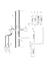
本発明の第1の実施の形態に係る乾き度測定装置は、図1に示すように、飽和液で吸収される波長を少なくとも有する検査光を発する検査光発光器11と、内部に湿り蒸気を流す検査管21であって、検査光発光器11から発生された検査光が入射する第1の窓121Aと、当該検査管21の内部を透過した検査光が出射する第2の窓121Bと、が設けられた検査管21と、検査管21を通過した検査光を受光する受光器12と、受光された検査光の光強度に基づき、湿り蒸気の乾き度を特定する乾き度特定部301と、を備える。第1及び第2の窓121A、121Bの少なくとも一方は、親水性処理されている。乾き度特定部301は、例えば、中央演算処理装置(CPU)300に含まれている。
本発明の第1の実施の形態に係る乾き度測定装置は、図1に示すように、飽和液で吸収される波長を少なくとも有する検査光を発する検査光発光器11と、内部に湿り蒸気を流す検査管21であって、検査光発光器11から発生された検査光が入射する第1の窓121Aと、当該検査管21の内部を透過した検査光が出射する第2の窓121Bと、が設けられた検査管21と、検査管21を通過した検査光を受光する受光器12と、受光された検査光の光強度に基づき、湿り蒸気の乾き度を特定する乾き度特定部301と、を備える。第1及び第2の窓121A、121Bの少なくとも一方は、親水性処理されている。乾き度特定部301は、例えば、中央演算処理装置(CPU)300に含まれている。
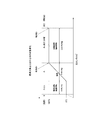
検査管21には、飽和蒸気と、飽和液と、が合わさった湿り蒸気が通過しうる。図2に示すように、標準大気圧下においては、水は沸点(100℃)に達した後、液滴としての水と、蒸気と、が混合し、共存態にある湿り蒸気となる。圧力が一定の場合、湿り蒸気は加熱及び冷却により潜熱が変化するため、飽和温度は一定となる。ここで、下記(1)式で与えられるように、湿り蒸気全量に対する、飽和蒸気の質量比を、「乾き度」という。したがって、飽和蒸気の乾き度は1となり、飽和液の乾き度は0となる。
z=mvapor/(mvapor+mwater) (1)
zは乾き度、mvaporは飽和蒸気の質量、mwaterは飽和液の質量を表す。
z=mvapor/(mvapor+mwater) (1)
zは乾き度、mvaporは飽和蒸気の質量、mwaterは飽和液の質量を表す。
ここで、飽和蒸気の質量は、飽和蒸気の吸光度に比例する。また、飽和液の質量は、飽和液の吸光度に比例する。そのため、上記(1)式から下記(2)式が導かれる。
z=mvapor/(mvapor+mwater)
=avapor/(avapor+k×awater) (2)
avaporは飽和蒸気の吸光度、awaterは飽和液の吸光度、kは下記(3)式で与えられるモル吸光係数比を表す。
k=evapor/ewater (3)
evaporは飽和蒸気の吸光係数、ewaterは飽和液の吸光係数を表す。
z=mvapor/(mvapor+mwater)
=avapor/(avapor+k×awater) (2)
avaporは飽和蒸気の吸光度、awaterは飽和液の吸光度、kは下記(3)式で与えられるモル吸光係数比を表す。
k=evapor/ewater (3)
evaporは飽和蒸気の吸光係数、ewaterは飽和液の吸光係数を表す。
湿り蒸気の吸光度Asは、下記(4)式で与えられるように、飽和蒸気の吸光度と、飽和液の吸光度と、の和で与えられる。
As=avapor+awater (4)
また、湿り蒸気の吸光度は、下記(5)式で与えられるように、湿り蒸気を透過する前の光の光強度に対する、湿り蒸気を透過した後の光の光強度の比の対数で与えられる。
As=-ln(Isteam1/Isteam0) (5)
Isteam0は湿り蒸気を透過する前、あるいは湿り蒸気が存在しない場合の光の光強度、Isteam1は湿り蒸気を透過した後の光の光強度を表す。
As=avapor+awater (4)
また、湿り蒸気の吸光度は、下記(5)式で与えられるように、湿り蒸気を透過する前の光の光強度に対する、湿り蒸気を透過した後の光の光強度の比の対数で与えられる。
As=-ln(Isteam1/Isteam0) (5)
Isteam0は湿り蒸気を透過する前、あるいは湿り蒸気が存在しない場合の光の光強度、Isteam1は湿り蒸気を透過した後の光の光強度を表す。
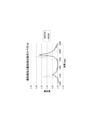
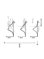
図3に示すように、飽和蒸気と飽和液の吸収スペクトルは異なり、乾き度が変化すると、飽和液の吸収スペクトルが変化する。例えば、乾き度が0から1に向かって変化するにつれて湿り蒸気における飽和液の含有量は減少するので、図4に示すように、飽和液の吸収スペクトルのピーク波長における湿り蒸気の吸光度Asも減少する。飽和液の吸収スペクトルのピークにおける波長は、1880nm付近である。なお、湿り蒸気においては、飽和蒸気の体積が飽和液の体積より非常に大きいため、圧力が一定であれば、飽和蒸気の吸光度は一定とみなすことができる。
湿り蒸気の乾き度は、上記(2)式、(4)式及び(5)式から導かれる下記(6)式でも与えられる。
z=1/(1-k+(k/avapor)×AS) (6)
モル吸光係数比kは定数である。上述したように、飽和蒸気の吸光度avaporは一定圧力下では一定とみなせるため、飽和蒸気の吸光度avaporは湿り蒸気の圧力から導くことができる。そのため、湿り蒸気の吸光度ASを測定することにより、(6)式から湿り蒸気の乾き度zを算出することが可能である。
z=1/(1-k+(k/avapor)×AS) (6)
モル吸光係数比kは定数である。上述したように、飽和蒸気の吸光度avaporは一定圧力下では一定とみなせるため、飽和蒸気の吸光度avaporは湿り蒸気の圧力から導くことができる。そのため、湿り蒸気の吸光度ASを測定することにより、(6)式から湿り蒸気の乾き度zを算出することが可能である。
図1に示す検査光発光器11は、飽和液によって吸収される波長帯域を含む検査光を発する。検査光は、例えば、波長領域800nmから2500nmの近赤外光である。図4に示すように、検査光は、飽和液の吸収スペクトルのピーク波長を中心波長としてもよい。当該波長領域において、飽和蒸気と飽和液の吸収スペクトルは重なりあっている。図1に示す検査光発光器11には、発光ダイオード等が使用可能である。
検査管21に設けられた第1の窓121Aと、第2の窓121Bと、は、対向している。第1及び第2の窓121A、121Bは、例えば耐熱ガラス等の石英ガラスからなる。第1及び第2の窓121A、121Bの少なくとも一方が、波長が10nmから400nmの紫外線(UV)照射処理により、親水性処理されている。あるいは、第1及び第2の窓121A、121Bの少なくとも一方が、酸化チタン(TiO2)及び酸化亜鉛(ZnO)等の光触媒で覆われることにより、親水性処理されている。他に、第1及び第2の窓121A、121Bの少なくとも一方を親水性処理する方法としては、減圧プラズマ処理、大気圧プラズマ処理、オゾン処理、界面活性剤コーティング処理、及び親水性樹脂コーティング処理等があるが、これらに限定されない。
例えば、第1の窓121Aが重力方向上側、第2の窓121Bが重力方向下側に配置される場合は、第2の窓121Bの内表面上には液体の水が流れやすくなるため、第1の窓121Aの内表面のみが、親水性処理されてよい。ただし、第1の窓121Aの外表面、第2の窓121Bの内表面、及び第2の窓121Bの外表面も親水性処理されてよい。
第1及び第2の窓121A、121Bが設けられた耐熱性の検査管21は、例えば、サイトグラスである。検査光発光器11と、第1の窓121Aの外面の間に、コリメータレンズを配置してもよい。
検査光発光器11から発せられた検査光は、検査管21の内部において、湿り蒸気に含まれる飽和液によって吸収される。上述したように、湿り蒸気に含まれる飽和液は、乾き度が0から1に近づくにつれて減少する。したがって、検査管21内部の湿り蒸気の乾き度が0から1に近づくにつれて、検査光に対する湿り蒸気の吸光度は低下する傾向にある。
検査管21の第2の窓121Bの外面に、検査管21の内部を通過した検査光を受光する受光器12が対向している。受光器12には、フォトダイオード等の光強度検出素子が使用可能である。第2の窓121Bの外面と、受光器12の間に、受光器12に検査光を入射させるレンズを配置してもよい。
第1の実施の形態に係る乾き度測定装置は、検査管21内の湿り蒸気の圧力を測定する圧力センサ16をさらに備えていてもよい。ただし、圧力の情報は、検査管21の上流や下流から得てもよい。
受光器12及び圧力センサ16は、CPU300に接続されている。CPU300には、関係記憶装置400が接続されている。関係記憶装置400は、例えば、上記(5)式及び(6)式のような、湿り蒸気の吸光度と、湿り蒸気の乾き度と、の関係式を保存する。
乾き度特定部301は、受光器12から、検査管21の内部の湿り蒸気を透過した検査光の光強度の測定値を受信する。また、乾き度特定部301は、関係記憶装置400から関係式を読み出す。さらに、乾き度特定部301は、受光器12が受光した検査光の光強度Isteam1に基づき、例えば上記(5)式に従って、検査管21内の湿り蒸気の吸光度ASを特定する。なお、湿り蒸気を透過する前、あるいは検査管21内に湿り蒸気が存在しない場合の検査光の光強度Isteam0は、予め測定した値を定数として用いてもよい。また、乾き度特定部301は、圧力センサ16から、検査管21内の湿り蒸気の圧力の測定値を受信する。
乾き度特定部301は、圧力センサ16から受信した検査管21内の湿り蒸気の圧力の測定値に基づき、圧力に依存する飽和蒸気の吸光度avaporを算出する。さらに、乾き度特定部301は、例えば上記(6)式に、検査管21の内部における湿り蒸気の吸光度ASの値と、飽和蒸気の吸光度avaporの値と、を代入し、検査管21内の湿り蒸気の乾き度zを算出する。ただし、圧力が一定であれば、飽和蒸気の吸光度avaporは一定であるとみなせるため、検査管21内の圧力が一定であれば、飽和蒸気の吸光度avaporに定数を用いてもよい。この場合、第1の実施の形態に係る乾き度測定装置は、圧力センサ16を備えていなくてもよい。
CPU300には、さらに入力装置321、出力装置322、プログラム記憶装置323、及び一時記憶装置324が接続される。入力装置321としては、スイッチ及びキーボード等が使用可能である。関係記憶装置400に保存される関係式は、例えば、入力装置321を用いて入力される。出力装置322としては、光インジケータ、デジタルインジケータ、及び液晶表示装置等が使用可能である。
出力装置322は、例えば、乾き度特定部301が特定した検査管21内部の湿り蒸気の乾き度の値を出力する。プログラム記憶装置323は、CPU300に接続された装置間のデータ送受信等をCPU300に実行させるためのプログラムを保存している。一時記憶装置324は、CPU300の演算過程でのデータを一時的に保存する。
以上説明した第1の実施の形態に係る乾き度測定装置によれば、検査管21に設けられた第1及び第2の窓121A、121Bの少なくとも一方が、親水性処理されている。そのため、第1及び第2の窓121A、121Bの少なくとも一方に水滴が付着しにくくなる。仮に第1及び第2の窓の少なくとも一方が親水性処理されていない場合、第1及び第2の窓に水滴が容易に付着し、検査光が水滴により屈折や散乱して、受光器で受光できる検査光の光量が減少しうる。これに対し、第1の実施の形態に係る乾き度測定装置によれば、検査光が水滴により屈折や散乱することを抑制し、受光器で受光できる検査光の光量が減少することを抑制することが可能となる。そのため、湿り蒸気における検査光の吸光度に基づき、高い精度で、湿り蒸気の乾き度を測定することが可能となる。
(第2の実施の形態)
本発明の第2の実施の形態に係る乾き度測定装置は、図5に示すように、飽和液で吸収される波長を少なくとも有する検査光を発する検査光発光器11と、内部に湿り蒸気を流す検査管21であって、検査光発光器11から発生された検査光が入射する第1の窓221Aと、当該検査管21の内部を透過した検査光が出射する第2の窓221Bと、が設けられた検査管21と、検査管21を通過した検査光を受光する受光器12と、受光された検査光の光強度に基づき、湿り蒸気の乾き度を特定する乾き度特定部301と、第1及び第2の窓の少なくとも一方に紫外線を照射する紫外線照射器111と、を備える。
本発明の第2の実施の形態に係る乾き度測定装置は、図5に示すように、飽和液で吸収される波長を少なくとも有する検査光を発する検査光発光器11と、内部に湿り蒸気を流す検査管21であって、検査光発光器11から発生された検査光が入射する第1の窓221Aと、当該検査管21の内部を透過した検査光が出射する第2の窓221Bと、が設けられた検査管21と、検査管21を通過した検査光を受光する受光器12と、受光された検査光の光強度に基づき、湿り蒸気の乾き度を特定する乾き度特定部301と、第1及び第2の窓の少なくとも一方に紫外線を照射する紫外線照射器111と、を備える。
紫外線照射器111が紫外線を照射することにより、第1及び第2の窓221A、221Bの少なくとも一方が親水性処理される。紫外線照射器111は、例えば、第1の窓221Aの外表面と対向している。これにより、少なくとも、第1の窓221Aの外表面と内表面が、紫外線照射により、親水性処理される。また、第1の窓221Aを透過した紫外線により、第2の窓221Bの外表面と内表面も、親水性処理される。紫外線照射器111としては、例えば波長184.9nm又は253.7nmの紫外線を発する紫外線ランプ等が使用可能である。
例えば、第1の窓221Aが重力方向上側、第2の窓221Bが重力方向下側に配置される場合は、第2の窓221Bの内表面上には液体の水が流れやすくなるため、第1の窓221Aの内表面のみが、親水性処理されればよい場合もある。この場合、第2の窓221Bの内表面に紫外線反射膜を設けて、第1の窓221Aを透過した紫外線を第2の窓221B上で反射させ、第1の窓221Aの内表面に入射させてもよい。これにより、紫外線の有効利用が可能となる。
また、第2の実施の形態において、第1の窓221Aの内表面、第1の窓221Aの外表面、第2の窓221Bの内表面、及び第2の窓221Bの外表面のそれぞれは、予め、紫外線照射器111による紫外線照射とは別の方法で親水性処理されていてもよいし、親水性処理されていなくともよい。
第2の実施の形態に係る乾き度測定装置のその他の構成要素は、第1の実施の形態と同様である。
(第3の実施の形態)
第3の実施の形態に係る乾き度測定装置においては、図6に示すように、検査光発光器11に対向して、検査光を伝搬する検査光導波路30が配置されている。また、紫外線照射器111に対向して、紫外線を伝搬する紫外線導波路130が配置されている。検査光導波路30と紫外線導波路130には、合波器14が接続されている。
第3の実施の形態に係る乾き度測定装置においては、図6に示すように、検査光発光器11に対向して、検査光を伝搬する検査光導波路30が配置されている。また、紫外線照射器111に対向して、紫外線を伝搬する紫外線導波路130が配置されている。検査光導波路30と紫外線導波路130には、合波器14が接続されている。
合波器14には、合波器14で合波された検査光と紫外線を、検査管21の内部に伝搬するための合波光導波路31が接続されている。合波光導波路31は、例えば、検査管21に設けられた窓221Aの外面に接続されている。合波光導波路31の端部と、窓221Aの外面の間に、コリメータレンズを配置してもよい。
検査管21の窓221Bの外面には、検査管21の内部を通過した検査光が進入する受光用導波路51が接続されている。受光用導波路51の端部は、合波光導波路31の端部と対向している。窓221Bの外面と、受光用導波路51の端部の間に、受光用導波路51に検査光を入射させるレンズを配置してもよい。受光用導波路51は、検査管21の内部を透過した検査光を、受光器12に導く。
検査光導波路30、紫外線導波路130、合波光導波路31、及び受光用導波路51には、ポリメタクリル酸メチル樹脂(PMMA:Poly(methyl methacrylate))等のプラスチックからなるシングルコア光ファイバ、及び石英ガラス等のガラスからなるシングルコア光ファイバ等が使用可能であるが、これらに限定されない。
例えば、第1の窓221Aが重力方向上側、第2の窓221Bが重力方向下側に配置される場合は、第2の窓221Bの内表面上には液体の水が流れやすくなるため、第1の窓221Aの内表面のみが、親水性処理されればよい場合もある。この場合、第2の窓221Bの内表面に紫外線反射膜を設けて、第1の窓221Aを透過した紫外線を第2の窓221B上で反射させ、第1の窓221Aの内表面に入射させてもよい。これにより、紫外線の有効利用が可能となる。
第3の実施の形態において、第1の窓221Aの内表面、第1の窓221Aの外表面、第2の窓221Bの内表面、及び第2の窓221Bの外表面のそれぞれは、予め、紫外線照射器111による紫外線照射とは別の方法で親水性処理されていてもよいし、親水性処理されていなくともよい。
第3の実施の形態に係る乾き度測定装置のその他の構成要素は、第2の実施の形態と同様である。
(その他の実施の形態)
上記のように本発明を実施の形態によって記載したが、この開示の一部をなす記述及び図面はこの発明を限定するものであると理解するべきではない。この開示から当業者には様々な代替実施の形態、実施例及び運用技術が明らかになるはずである。例えば、受光器による受光強度と、湿り蒸気の乾き度と、の関係は、ボイラ等で湿り蒸気を加熱しながら、従来の乾き度測定方法で湿り蒸気の乾き度を測定し、あわせて湿り蒸気を透過した検査光の強度を測定することによって、予め取得してもよい。従来、種々の乾き度測定方法があるが、関係を取得する際には、それらのいずれかを単独で用いても、組み合わせて用いてもよい。また、受光素子による受光強度と、湿り蒸気の乾き度と、の関係は、表として保存されてもよい。このように、本発明はここでは記載していない様々な実施の形態等を包含するということを理解すべきである。
上記のように本発明を実施の形態によって記載したが、この開示の一部をなす記述及び図面はこの発明を限定するものであると理解するべきではない。この開示から当業者には様々な代替実施の形態、実施例及び運用技術が明らかになるはずである。例えば、受光器による受光強度と、湿り蒸気の乾き度と、の関係は、ボイラ等で湿り蒸気を加熱しながら、従来の乾き度測定方法で湿り蒸気の乾き度を測定し、あわせて湿り蒸気を透過した検査光の強度を測定することによって、予め取得してもよい。従来、種々の乾き度測定方法があるが、関係を取得する際には、それらのいずれかを単独で用いても、組み合わせて用いてもよい。また、受光素子による受光強度と、湿り蒸気の乾き度と、の関係は、表として保存されてもよい。このように、本発明はここでは記載していない様々な実施の形態等を包含するということを理解すべきである。
本発明の実施の形態に係る乾き度測定装置は、減圧弁による潜熱増加効果の可視化、最適ボイラ効率を得るための乾き度計測、水蒸気タービンの湿り損失計測、熱交換器の最適乾き度制御、製麺蒸し工程等の食品製造工程の制御、及び化学工程の制御等に利用可能である。
11 検査光発光器
12 受光器
14 合波器
16 圧力センサ
21 検査管
30 検査光導波路
31 合波光導波路
51 受光用導波路
111 紫外線照射器
121A 第1の窓
121B 第2の窓
130 紫外線導波路
221A 第1の窓
221B 第2の窓
300 中央演算処理装置
301 乾き度特定部
321 入力装置
322 出力装置
323 プログラム記憶装置
324 一時記憶装置
400 関係記憶装置
12 受光器
14 合波器
16 圧力センサ
21 検査管
30 検査光導波路
31 合波光導波路
51 受光用導波路
111 紫外線照射器
121A 第1の窓
121B 第2の窓
130 紫外線導波路
221A 第1の窓
221B 第2の窓
300 中央演算処理装置
301 乾き度特定部
321 入力装置
322 出力装置
323 プログラム記憶装置
324 一時記憶装置
400 関係記憶装置
Claims (11)
- 飽和液で吸収される波長を少なくとも有する検査光を発する検査光発光器と、
内部に湿り蒸気を流す検査管であって、前記検査光発光器から発生された前記検査光が入射する第1の窓と、当該検査管の内部を透過した前記検査光が出射する第2の窓と、が設けられた検査管と、
前記検査管を通過した前記検査光を受光する受光器と、
前記受光された前記検査光の光強度に基づき、前記湿り蒸気の乾き度を特定する乾き度特定部と、
を備え、
前記第1及び第2の窓の少なくとも一方が、親水性処理されている、
乾き度測定装置。 - 前記第1及び第2の窓の少なくとも一方が、紫外線照射処理されている、請求項1に記載の乾き度測定装置。
- 前記第1及び第2の窓の少なくとも一方が、光触媒で覆われている、請求項1に記載の乾き度測定装置。
- 前記第1の窓が重力方向上側、前記第2の窓が重力方向下側に配置され、
前記第1の窓が、親水性処理されている、
請求項1から3のいずれか1項に記載の乾き度測定装置。 - 飽和液で吸収される波長を少なくとも有する検査光を発する検査光発光器と、
内部に湿り蒸気を流す検査管であって、前記検査光発光器から発生された前記検査光が入射する第1の窓と、当該検査管の内部を透過した前記検査光が出射する第2の窓と、が設けられた検査管と、
前記検査管を通過した前記検査光を受光する受光器と、
前記受光された前記検査光の光強度に基づき、前記湿り蒸気の乾き度を特定する乾き度特定部と、
前記第1及び第2の窓の少なくとも一方に紫外線を照射する紫外線照射器と、
を備える、
乾き度測定装置。 - 紫外線照射器が前記第1の窓の外表面と対向している、請求項5に記載の乾き度測定装置。
- 前記第2の窓の内表面に紫外線反射膜が設けられている、請求項6に記載の乾き度測定装置。
- 前記第1の窓が重力方向上側、前記第2の窓が重力方向下側に配置される、請求項5から7のいずれか1項に記載の乾き度測定装置。
- 前記第1及び第2の窓の少なくとも一方が、予め紫外線照射処理されている、請求項5から8のいずれか1項に記載の乾き度測定装置。
- 前記第1及び第2の窓の少なくとも一方が、光触媒で覆われている、請求項5から8のいずれか1項に記載の乾き度測定装置。
- 前記検査光と前記紫外線を合波する合波器と、
前記合波された検査光と紫外線を前記第1の窓に伝搬する合波光導波路と、
を更に備える、請求項5から10のいずれか1項に記載の乾き度測定装置。
Applications Claiming Priority (2)
| Application Number | Priority Date | Filing Date | Title |
|---|---|---|---|
| JP2015-211264 | 2015-10-27 | ||
| JP2015211264A JP6664926B2 (ja) | 2015-10-27 | 2015-10-27 | 乾き度測定装置 |
Publications (1)
| Publication Number | Publication Date |
|---|---|
| WO2017073256A1 true WO2017073256A1 (ja) | 2017-05-04 |
Family
ID=58630297
Family Applications (1)
| Application Number | Title | Priority Date | Filing Date |
|---|---|---|---|
| PCT/JP2016/079406 Ceased WO2017073256A1 (ja) | 2015-10-27 | 2016-10-04 | 乾き度測定装置 |
Country Status (2)
| Country | Link |
|---|---|
| JP (1) | JP6664926B2 (ja) |
| WO (1) | WO2017073256A1 (ja) |
Cited By (1)
| Publication number | Priority date | Publication date | Assignee | Title |
|---|---|---|---|---|
| CN113670396A (zh) * | 2021-07-27 | 2021-11-19 | 北京空间飞行器总体设计部 | 一种气液两相流体干度测量装置及方法 |
Citations (4)
| Publication number | Priority date | Publication date | Assignee | Title |
|---|---|---|---|---|
| JP2003121354A (ja) * | 2001-10-16 | 2003-04-23 | Toyobo Co Ltd | 非接触水分率測定装置及び非接触水分率測定方法 |
| JP2004188297A (ja) * | 2002-12-10 | 2004-07-08 | Ichikoh Ind Ltd | 光触媒活性構造 |
| JP2004340895A (ja) * | 2003-05-19 | 2004-12-02 | Olympus Corp | 生体関連物質の検査容器と検出装置 |
| JP2015127647A (ja) * | 2013-12-27 | 2015-07-09 | アズビル株式会社 | 乾き度測定装置 |
-
2015
- 2015-10-27 JP JP2015211264A patent/JP6664926B2/ja not_active Expired - Fee Related
-
2016
- 2016-10-04 WO PCT/JP2016/079406 patent/WO2017073256A1/ja not_active Ceased
Patent Citations (4)
| Publication number | Priority date | Publication date | Assignee | Title |
|---|---|---|---|---|
| JP2003121354A (ja) * | 2001-10-16 | 2003-04-23 | Toyobo Co Ltd | 非接触水分率測定装置及び非接触水分率測定方法 |
| JP2004188297A (ja) * | 2002-12-10 | 2004-07-08 | Ichikoh Ind Ltd | 光触媒活性構造 |
| JP2004340895A (ja) * | 2003-05-19 | 2004-12-02 | Olympus Corp | 生体関連物質の検査容器と検出装置 |
| JP2015127647A (ja) * | 2013-12-27 | 2015-07-09 | アズビル株式会社 | 乾き度測定装置 |
Cited By (2)
| Publication number | Priority date | Publication date | Assignee | Title |
|---|---|---|---|---|
| CN113670396A (zh) * | 2021-07-27 | 2021-11-19 | 北京空间飞行器总体设计部 | 一种气液两相流体干度测量装置及方法 |
| CN113670396B (zh) * | 2021-07-27 | 2023-11-07 | 北京空间飞行器总体设计部 | 一种气液两相流体干度测量装置及方法 |
Also Published As
| Publication number | Publication date |
|---|---|
| JP6664926B2 (ja) | 2020-03-13 |
| JP2017083271A (ja) | 2017-05-18 |
Similar Documents
| Publication | Publication Date | Title |
|---|---|---|
| US8610894B2 (en) | Dryness fraction measuring device and dryness fraction measuring method | |
| JP5885461B2 (ja) | 乾き度測定装置及び乾き度測定方法 | |
| US9372153B2 (en) | Dryness fraction distribution measuring device and dryness fraction distribution measuring method | |
| US12078590B2 (en) | Concentration measuring method, and concentration measuring device | |
| JPWO2020066769A5 (ja) | ||
| JP6664926B2 (ja) | 乾き度測定装置 | |
| JP2016151572A (ja) | 乾き度測定装置 | |
| JP6175370B2 (ja) | 乾き度測定装置及び乾き度測定方法 | |
| JP6006605B2 (ja) | 蒸気流量測定装置および蒸気流量測定方法 | |
| WO2018135130A1 (ja) | 乾き度測定装置及び乾き度の測定方法 | |
| WO2017104241A1 (ja) | 乾き度測定装置 | |
| JP2015232520A (ja) | 乾き度測定装置 | |
| WO2017183433A1 (ja) | 乾き度測定装置及び湿り蒸気検査装置 | |
| US9625384B2 (en) | Dryness fraction distribution measuring device and dryness fraction distribution measuring method | |
| WO2017203841A1 (ja) | 乾き度測定装置及び湿り蒸気検査装置 | |
| JP6392661B2 (ja) | 乾き度測定装置 | |
| JP6379007B2 (ja) | 配管および乾き度測定装置 | |
| JP2011122886A (ja) | 温度測定装置および温度測定方法 | |
| JP2017194348A (ja) | 乾き度測定装置及び湿り蒸気検査装置 | |
| JP6307427B2 (ja) | 乾き度測定装置及び乾き度測定方法 | |
| JP2018119861A (ja) | 乾き度測定装置及び乾き度の測定方法 | |
| JP2016151571A (ja) | 乾き度測定装置 | |
| KR20130110318A (ko) | 직접흡수광법을 이용한 가스농도 산출기법 | |
| JP6392627B2 (ja) | 乾き度測定装置および乾き度測定方法 | |
| JP2019052925A (ja) | 乾き度測定装置及び乾き度測定方法 |
Legal Events
| Date | Code | Title | Description |
|---|---|---|---|
| 121 | Ep: the epo has been informed by wipo that ep was designated in this application |
Ref document number: 16859493 Country of ref document: EP Kind code of ref document: A1 |
|
| NENP | Non-entry into the national phase |
Ref country code: DE |
|
| 122 | Ep: pct application non-entry in european phase |
Ref document number: 16859493 Country of ref document: EP Kind code of ref document: A1 |