WO2017073134A1 - 空気清浄機 - Google Patents
空気清浄機 Download PDFInfo
- Publication number
- WO2017073134A1 WO2017073134A1 PCT/JP2016/073754 JP2016073754W WO2017073134A1 WO 2017073134 A1 WO2017073134 A1 WO 2017073134A1 JP 2016073754 W JP2016073754 W JP 2016073754W WO 2017073134 A1 WO2017073134 A1 WO 2017073134A1
- Authority
- WO
- WIPO (PCT)
- Prior art keywords
- water
- air
- tank
- air cleaner
- unit
- Prior art date
- Legal status (The legal status is an assumption and is not a legal conclusion. Google has not performed a legal analysis and makes no representation as to the accuracy of the status listed.)
- Ceased
Links
Images






Classifications
-
- B—PERFORMING OPERATIONS; TRANSPORTING
- B60—VEHICLES IN GENERAL
- B60H—ARRANGEMENTS OF HEATING, COOLING, VENTILATING OR OTHER AIR-TREATING DEVICES SPECIALLY ADAPTED FOR PASSENGER OR GOODS SPACES OF VEHICLES
- B60H1/00—Heating, cooling or ventilating devices
- B60H1/0025—Heating, cooling or ventilating devices the devices being independent of the vehicle
- B60H1/00264—Transportable devices
-
- A—HUMAN NECESSITIES
- A61—MEDICAL OR VETERINARY SCIENCE; HYGIENE
- A61L—METHODS OR APPARATUS FOR STERILISING MATERIALS OR OBJECTS IN GENERAL; DISINFECTION, STERILISATION OR DEODORISATION OF AIR; CHEMICAL ASPECTS OF BANDAGES, DRESSINGS, ABSORBENT PADS OR SURGICAL ARTICLES; MATERIALS FOR BANDAGES, DRESSINGS, ABSORBENT PADS OR SURGICAL ARTICLES
- A61L9/00—Disinfection, sterilisation or deodorisation of air
- A61L9/14—Disinfection, sterilisation or deodorisation of air using sprayed or atomised substances including air-liquid contact processes
-
- B—PERFORMING OPERATIONS; TRANSPORTING
- B60—VEHICLES IN GENERAL
- B60H—ARRANGEMENTS OF HEATING, COOLING, VENTILATING OR OTHER AIR-TREATING DEVICES SPECIALLY ADAPTED FOR PASSENGER OR GOODS SPACES OF VEHICLES
- B60H3/00—Other air-treating devices
- B60H3/02—Moistening ; Humidity control
-
- B—PERFORMING OPERATIONS; TRANSPORTING
- B60—VEHICLES IN GENERAL
- B60H—ARRANGEMENTS OF HEATING, COOLING, VENTILATING OR OTHER AIR-TREATING DEVICES SPECIALLY ADAPTED FOR PASSENGER OR GOODS SPACES OF VEHICLES
- B60H3/00—Other air-treating devices
- B60H3/06—Filtering
-
- F—MECHANICAL ENGINEERING; LIGHTING; HEATING; WEAPONS; BLASTING
- F24—HEATING; RANGES; VENTILATING
- F24F—AIR-CONDITIONING; AIR-HUMIDIFICATION; VENTILATION; USE OF AIR CURRENTS FOR SCREENING
- F24F6/00—Air-humidification, e.g. cooling by humidification
- F24F6/12—Air-humidification, e.g. cooling by humidification by forming water dispersions in the air
Definitions
- the present invention relates to an air purifier that purifies the air in the space by supplying air containing active species having an air purification action or ions that generate active species to the space.
- Patent Document 1 discloses an in-vehicle air cleaner having an ion generator (active species generator) that generates one or both of positive ions and negative ions that generate active species.
- Patent Document 2 discloses an in-vehicle air cleaner that has an ozone generator (active species generator) that generates ozone and discharges negative ion wind containing ozone.
- Patent Document 3 discloses an in-vehicle humidifier equipped with a mist generating device that generates mist using an ultrasonic transducer.
- This invention is made
- an air purifier can be installed in a drink holder, a blower unit that sucks in external air, an air passage that guides the sucked air to a blowout port, An air purifier arranged facing the air path and having an active species generating unit that generates active species that purify air or ions that generate the active species, and a water storage unit that can store water
- the water-absorbing part is further provided with a water-absorbing part that absorbs water by immersing the lower end side in the water in the water-reserving part, and a mist generating part that generates mist in contact with the upper end of the water-absorbing part.
- both the air purifying function and the mist generating function can be installed in the drink holder, and the air in the space is moistened by using only one drink holder. There is an effect that it can be made more comfortable.
- FIG. 4 is a cross-sectional view taken along line AA in FIG. FIG.
- FIG. 6 is a cross-sectional view showing a state where the tank unit is pulled obliquely downward from the state of FIG. 5 and detached from the main unit. It is a perspective view which shows the external appearance structure of the said tank unit.
- (A) is the front view which shows the structure of the side facing the main body unit in the said tank unit, the front view which shows an inner structure
- (b) is a right view of the said tank unit.
- It is explanatory drawing which shows the state which attaches the said tank unit to the said main body unit.
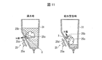
- It is sectional drawing which shows the state which attaches the said tank unit to the said main body unit. It is drawing explaining the water level detection part which detects the water level of the tank mounted in the said tank unit, and shows the state at the time of a water absorption warning with a sufficiently high water level and a low water level.
- FIG. 1 is a perspective view showing a state in which the air purifier 1 of the present embodiment is housed in a drink holder 60 in an automobile.
- the air purifier 1 supplies air containing an active species having an air purification action (or ions that generate the active species) to purify the air in the vehicle, and also releases the mist to release the mist. It has a mist generating function that moisturizes and provides a more comfortable space.
- the air purifier 1 is detachably installed in the drink holder 60, and at least the lower part 1a is formed in a shape that fits in the drink holder 60, in this case, a cylindrical shape.
- the drink holder 60 is installed obliquely forward as viewed from the driver, but the drink provided in the luggage space between the driver seat and the passenger seat is illustrated. It can also be installed in a holder or a drink holder provided for the rear seat. Also, the drink holder is not limited to a standard one provided in the car from the beginning, but may be a retrofit type that can be purchased at a commercial store.
- the power supply to the air purifier 1 may be configured from the cigar socket 61, or may be configured from the USB port if the vehicle has a USB port.
- a battery or a battery may be mounted.
- the detailed structure of the air cleaner 1 is demonstrated.
- FIG. 2 is a perspective view showing the external appearance of the air purifier 1.
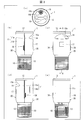
- FIG. 3 is a diagram showing each surface of the air purifier 1, wherein (a) is a plan view, (b) is a left side view, (c) is a front view, (d) is a right side view, and (e).
- FIG. FIG. 4 is a perspective view showing a state in which the air purifier 1 is separated into the main unit 20 and the tank unit 30.
- the air purifier 1 has a lower part 1a formed in a cylindrical shape that fits into the drink holder 60 (see FIG. 1), and an upper part 1b protruding from the drink holder 60. Is formed in a cylindrical shape having a diameter larger than that of the lower portion 1a.
- the shapes of the lower part 1a and the upper part 1b are both cylindrical, but the present invention is not limited to this.
- the upper portion 1b may have any shape such as a triangular prism shape, a quadrangular prism shape, or a spherical shape.
- a columnar shape is most desirable in terms of stability, but may be a rectangular parallelepiped shape or the like as long as it fits into the drink holder 60.
- the air cleaner 1 includes a lower casing 10 formed in a bottomed cylindrical shape in the lower portion 1a, and an upper casing 11 formed in a cylindrical shape in the upper portion 1b and an upper opening of the upper casing 11. And a circular lid 12 for closing.
- a blower (blower unit) 21 to be described later is accommodated in the lower casing 10, and an ion generator (active species generator) 23, an air path 22, and a tank (water storage) to be described later are stored in the upper casing 11.
- Part) 31 a water absorption mechanism 32, a mist generating part 24, a water level detecting part 25, and the like (see FIG. 5).
- An air suction port 13 is provided on the outer peripheral surface of the lower housing 10.
- the air suction port 13 includes a plurality of arc-shaped slit holes formed on the outer peripheral surface of the lower housing 10. As the fan 21c (see FIG. 5) of the blower 21 inside the lower housing 10 rotates, air is sucked into the air purifier 1 from the air suction port 13 and sent to the air path 22.
- the lower housing 10 is formed, for example, with a bottom diameter of 65 mm and a cylindrical height of 70 mm.
- the upper housing 11 is divided into a semi-cylindrical front upper housing 11 a located on the front side of the air cleaner 1 and a semi-cylindrical rear upper housing 11 b located on the back side of the air cleaner 1.
- a pair of engaging recesses 29 are formed at both end portions of the inner peripheral surface of the front upper casing 11a in the circumferential direction that abuts the rear upper casing 11b.
- a lock claw 35 (see FIG. 4, FIG. 7, FIG. 8, FIG. 9, etc.), which will be described later, formed in the rear upper housing 11 b is snap-fit engaged with these engaging recesses 29, so that the rear upper housing
- the body 11b can be attached to and detached from the front upper casing 11a.
- the lower end of the front upper casing 11a is joined to the lower casing 10, and the lid 12 is fitted to the upper end thereof.
- the front upper housing 11a and the lower housing 10 may be integrally formed as a synthetic resin molded product.
- An opening is provided in the outer peripheral surface of the front upper casing 11a in the center in the circumferential direction on the upper end side, and air containing ions having an air purification action (hereinafter referred to as ion wind) is blown out from the opening.
- the ion blowing part 14 is exposed.
- the ion blow-out portion 14 has a wedge-shaped recess 16 that is long in the circumferential direction, and an air outlet 15 that is connected to the air passage 22 is formed on the flat surface below the recess 16.
- the upper inclined surface 16a of the recess 16 functions as a guide plate for guiding the ionic wind blown from the air outlet 15 obliquely upward.
- the air passage 22 is inclined from the back side to the front side from the bottom to the top, and the inclined surface 16a on the upper side of the recess 16 has the same inclination as the air passage 22. is doing.
- an emblem 17 is affixed below the ion blowing part 14 on the outer peripheral surface of the front upper casing 11a.
- the rear upper casing 11b is configured to be detachable from the front upper casing 11a as described above.
- the tank (water storage part) 31 accommodated in the air cleaner 1 is exposed, and the tank 31 can be taken out.
- the tank 31 is attached to the inside of the rear upper housing 11b, and at the same time as the rear upper housing 11b is removed, the tank 31 can also be removed. .
- tank unit 30 the part integrally attached to and detached from the tank 31 is referred to as a tank unit 30, and the remaining part from which the tank unit 30 is removed from the air cleaner 1 is referred to as a main body unit (main body) 20.
- the lid 12 is provided with a mist discharge portion 18 for discharging mist.
- release part 18 is formed in the back side away from the front side of the air cleaner 1 in which the ion blowing part 14 is located.
- the mist emitting unit 18 includes a mist emitting port 18a that emits mist, a mortar-shaped light guide 18b provided around the mist discharge port 18a, and a light source 18c that includes an LED that supplies light to the light guide 18b. .
- the light guide 18b guides the light supplied from the light source 18c to the inside and converts it into a light source.
- the lid 12 is also provided with an operation display unit 19 that receives an instruction to switch the operation mode of the air cleaner 1 and displays the operation state in a lighting state.
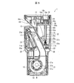
- FIG. 5 is a cross-sectional view taken along line AA in FIG. 6 is a cross-sectional view showing a state in which the tank unit 30 is pulled obliquely downward from the state of FIG. 5 and detached from the main unit.
- a blower 21, an air passage 22, an ion generation unit 23, a mist generation unit 24, a tank 31, a water absorption mechanism 32, a water level detection unit 25 and the like are disposed inside the air cleaner 1. Yes.
- the blower 21, the air passage 22, the ion generator 23, and the mist generator 24 are arranged on the main unit 20 side, and the tank 31 and the water absorption mechanism 32 are on the tank unit 30 side. Is arranged.
- the water level detection unit 25 is arranged separately on the main unit 20 side and the tank unit 30 side.
- the air passage 22 communicates the air suction port 13 formed in the lower housing 10 with the air outlet (air outlet) 15 of the ion outlet 14, and the fan 21 and the ion generator are connected to the air passage 22.
- 23 is arranged. With respect to the flow of the wind, the blower 21 is disposed on the upstream side, and the ion generator 23 is disposed on the downstream side.
- the duct extending from the outlet of the blower 21 toward the air outlet 15 in the air passage 22 is inclined from the back side to the front side. Therefore, the duct wall surface exposed when the tank unit 30 is removed is an inclined surface (second inclined surface) 22 a that is inclined from the back side to the front side of the air purifier 1.
- the blower 21 includes a casing portion 21a, a motor 21b fixed to the casing portion 21a, and a fan 21c rotated by the motor 21b.
- the blower 21 rotates the fan 21 c to suck in external air from the air inlet 13, and the sucked air is discharged from the air outlet 15 through the air passage 22.
- the ion generation unit 23 includes a discharge unit 23a, and generates one or both of positive ions and negative ions that generate active species having an air purification action from the discharge unit 23a by discharge.
- the discharge unit 23 a is disposed so as to face the air passage 22, and the generated ions are released as an ion wind from the air outlet 15 on the airflow flowing through the air passage 22.
- the mist generating unit 24 is disposed directly below the mist discharge port 18 a provided in the lid 12.
- the mist generating unit 24 includes an ultrasonic transducer 24a, and generates mist in contact with an upper end of a water absorbing rod (water absorbing unit) 32a of a water absorbing mechanism 32 described later. In order to generate mist, it is necessary for the ultrasonic transducer 24a to reliably contact the upper end of the water absorbing rod 32a.
- the mist generating part 24 is accommodated in an internal housing 50 located below the lid body 12, and the internal housing 50 is formed with an opening 50 a through which the water absorbing rod 32 a is inserted.
- the tank (water storage part) 31 is for storing water that becomes mist, and a water absorption rod 32 a of a water absorption mechanism 32 is installed inside the tank 31.
- a water absorption rod 32 a of a water absorption mechanism 32 is installed inside the tank 31.
- an inclined surface (first inclined surface) having an inclination along the inclined surface 22a is provided at a lower portion of the tank 31 and facing the inclined surface 22a on the main unit 20 side. It is formed in 31b.
- the water absorption mechanism 32 has a water absorption rod 32a, a water absorption rod guide 32b through which the water absorption rod 32a is inserted, and a spring 32c that urges the water absorption rod 32a upward.
- the water absorbing bar 32a is urged by a spring 32c from the lower end side, and the moving direction is restricted in the vertical direction by the water absorbing bar guide 32b.
- the water level detection unit 25 has a detected body 25b whose position changes according to the water level by being attached to the float 25c, and a detector 25a that detects the displacement of the detected body 25b, and controls the water level inside the tank 31. Detect.
- the float 25c and the detection target 25b are attached in the tank 31, and the detector 25a is attached to the main unit 20 side.
- FIG. 7 is a perspective view showing an external configuration of the tank unit 30.
- FIG. 8A is a front view showing the configuration of the tank unit 30 on the side facing the main unit 20, and
- FIG. 8B is a right side view of the tank unit 30.
- the tip of the water absorption rod 32 a protrudes from the upper surface of the tank 31, and a supply port 31 a for supplying water into the tank 31 is provided beside the water absorption rod 32 a. ing.
- a cap 33 is provided at the supply port 31a.
- the inclined surface 31b described above is formed on the lower side of the tank 31 on the side facing the main unit 20.
- the tank 31 is formed with an inclined surface 31b that is inclined obliquely downward on the side facing the main unit 20 so that the inner dimension becomes smaller toward the lower portion of the tank 31.
- the tank 31 has a shape in which the lower part is narrower than the upper part.
- the upper end of the tank 31 is regulated by two regulating claws 34 provided on the inner peripheral surface of the semi-cylindrical rear upper housing 11b.
- the lower end side of the tank 31 is fixed to the rear upper housing 11 b with a screw 39.
- a pair of engaging recesses 29 formed on the front upper housing 11a side described above are provided at both ends in the circumferential direction that face the front upper housing 11a in the rear upper housing 11b (see FIG. 2).
- a pair of lock claws 35 that are snap-fit engaged.
- finger contact projections 36 are also formed in the vicinity of each lock claw 35. The finger contact convex portion 36 facilitates bending the semi-cylindrical rear upper housing 11b inward, and facilitates engagement and disengagement between the lock claw 35 and the engagement concave portion 29. Is formed.
- the tank unit 30 is attached to the main unit 20 when the lock claw 35 engages with the engagement recess 29, and movement in the vertical direction is also restricted.
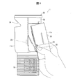
- FIG. 9 is an explanatory view showing a state in which the tank unit 30 is attached to the main unit 20.
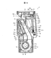
- FIG. 10 is a cross-sectional view showing a state in which the tank unit 30 is attached to the main unit 20.
- the tank unit 30 when attaching the tank unit 30, the user holds the tank unit 30 such that the thumb and middle finger or forefinger are hooked on the pair of finger contact projections 36 formed on the rear upper housing 11 b. To do. Then, the tank unit 30 is slanted, lifted from below to above and close to the main unit 20, and finally slightly rotated so as to be in the correct posture to engage the lock claw 35 with the engagement recess 29. Let To make the tank unit 30 slant, as shown in FIG. 10, it is necessary to insert the tip of the water absorption rod 32 a into the opening 50 a formed in the internal housing 50 below the lid 12 of the main unit 20. Because there is.
- the inclined surface 31b is provided on the tank unit 30 side, and the inclined surface 22a corresponding to this is provided on the main unit 20 side. Therefore, even if it is slanting, it can attach easily by inserting the inclined surface 31b by the side of the tank unit 30 along the inclined surface 22a by the side of the main unit 20.
- the user when removing the tank unit 30, the user holds the tank unit 30 in the same manner as described above, and first releases the engagement between the lock claw 35 and the engagement recess 29. Then, contrary to attachment, the tank unit 30 is rotated and inclined, and it removes so that it may pull out downward from upper direction. In this case, the tank unit 30 side can be easily removed by pulling out the inclined surface 31b on the tank unit 30 side along the inclined surface 22a on the main unit 20 side.
- the water level detection unit 25 includes the float 25c, the detected object 25b attached thereto, and the detector 25a.
- the float 25c and the detected object 25b are on the tank unit 30 side, and the detector 25a is not detected. Is attached to the side.
- the float 25c is rotatably supported by the inclined surface 31b in the tank 31.
- the float 25c floats in a state where the water level in the tank 31 is sufficiently high (when the water is full), rotates about the axis X as the water level decreases, and falls down along the inclined surface 31b during a water absorption warning.
- the detected body 25b is made of a magnet and attached to the rotation fulcrum side of the float 25c. In a state where the float 25c is sufficiently floated, the magnetic flux emitted from the detected body 25b is along the normal direction of the inclined surface 31b. On the other hand, in the state where the float 25c is tilted, the magnetic flux emitted from the detected body 25b is along a direction parallel to the inclined surface 31b.
- the detector 25a is provided with a Hall IC 25d, and detects the water level in the tank 31 by detecting the magnetic flux emitted from the detected body 25b and turning it on and off.
- the Hall IC 25d is turned on, and the detector 25a determines that the water level is sufficient.
- the Hall IC 25d is turned off, and the detector 25a determines that there is not enough water.
- the tank unit 30 is removed from the main unit 20, the Hall IC 25d remains in the OFF state regardless of the water level, so the detector 25a determines that there is not enough water.
- a control unit included in the air cleaner 1 stops the operation of the mist generation unit 24.
- the lighting of the light source 18c provided in the mist emitting unit 18 is switched from the constant lighting to the blinking lighting.
- the light guide 18b provided on the outer periphery of the mist discharge port 18a switches from constantly lighting to blinking lighting. Accordingly, it is possible to visually notify the user that the tank unit 30 has been removed or that the water in the tank 31 has been exhausted.
- the air purifier 1 is an air purifier that can be installed in a drink holder including a blower 21, an air passage 22, an ion generator 23, and the like, and further includes a tank 31, a water absorption mechanism 32, and a mist.
- the generator 24 is provided and also has a mist generating function (first embodiment).
- the blower 21 is further disposed in the lower portion 1 a of the air cleaner 1, and the tank 31 is disposed in the upper portion 1 b of the air cleaner above the blower 21 (second). Embodiment).
- the tank 31 is disposed above the blower 21. Since the blower 21 is made of a magnet that is a metal material, it is relatively heavy in the entire air cleaner 1. Therefore, in this configuration, even if the amount of water in the tank 31 changes, the center of gravity of the air purifier 1 does not change much. That is, as the amount of water in the tank 31 decreases, the center of gravity originally moves upward. With this configuration, the center of gravity can be brought down regardless of the amount of water in the tank 31. it can.
- the air purifier may fall from the drink holder 60, but the air purifier 1 can be stably installed in the drink holder 60 by lowering the position of the center of gravity. It becomes possible.
- the drink holder itself may be installed tilted, and the air cleaner is also subject to vibrations when traveling. Therefore, in such an air cleaner with a mist generating function, it is important to maintain a stable installation state regardless of the amount of water.
- the size and shape of the upper part 1b protruding above the drink holder 60 are not limited by the internal dimensions of the drink holder 60, the advantage that the design freedom such as the shape and capacity of the tank 31 can be increased. There is also.
- the water absorption rod 32 a is further installed in a tank 31 configured to be detachable (third embodiment).
- the tank 31 is further provided with an inclined surface 31 b that is inclined obliquely downward on the side facing the main unit 20 so that the inner dimension becomes smaller toward the lower part of the tank 31.
- the tank 31 has a shape in which the lower part is narrower than the upper part (fourth embodiment).
- the depth at which the lower end side of the water absorbing rod 32a is immersed can be ensured even when the water level with respect to the remaining water amount is high and the residual water is reduced.
- the amount of residual water that cannot be absorbed can be reduced as compared with a configuration that is not constricted, and the number of replenishments can be reduced when the tanks have the same capacity.
- an inclined surface 31b is further provided on the tank unit 30 side, and an inclined surface 22a corresponding to the inclined surface 31a is also provided on the body unit 20 side (fifth embodiment). .
- the tank unit 30 When the water absorbing rod 32a is installed on the tank unit 30 side, the tank unit 30 is inclined in order to make sure that the tip of the water absorbing rod 32a is in contact with the ultrasonic transducer 24a of the mist generating section 24 on the main unit 20 side. It needs to be lifted and rotated slightly to install. In such a slanted mounting, it is difficult to operate compared to mounting by moving straight from directly below, directly above, or from the side.
- the inclined surface 31b on the tank unit 30 side can be easily attached by being along the inclined surface 22a on the main unit 20 side.
- the float 25 c to which the detected body 25 b is attached in the water level detection unit 25 is rotatably installed on the inclined surface 31 b of the tank 31, and the detector 25 a In a state where the tank unit 30 is attached, the tank unit 30 is attached at a position facing the detected body 25b (sixth embodiment).
- the ultrasonic transducer 24a of the mist generating unit 24 breaks when it continues to vibrate in a state where water is not supplied, so that in a state where the water level is low or the tank unit 30 is removed, this is reliably detected, It is necessary to stop the ultrasonic transducer 24a. Therefore, a sensor for detecting the mounting state of the tank unit 30 is also required along with the detection of the water level.
- the float 25c to which the detected object 25b is attached is disposed on the tank 31 side, and the detector 25a is disposed on the main unit 20 side, so that the water level of the tank 31 can be obtained by one detector 25a.
- the detected object 25b is installed inside the tank 31 and cannot be easily touched, so that the ultrasonic transducer 24a is operated with the float 25c floating inadvertently. Can be prevented and damage to the ultrasonic transducer 24a can be prevented.
- the float 25c is provided at a constricted position where the water level with respect to the amount of residual water can be increased, even if it is pivotally supported from the bottom surface of the tank 31 to the same height position, compared to a tank that is not constricted, The remaining amount of water when the water level becomes the level of replenishment can be reduced.
- the mist discharge unit 18 is provided near the back surface of the lid 12 corresponding to the top surface of the air cleaner 1, and the ion blowing unit 14 corresponds to the outer peripheral surface of the air cleaner 1. It is provided on the front side upper part (seventh embodiment).
- the mist is discharged straight upward without being affected by the ion wind.
- the visual appearance can be improved.
- the air cleaner 1 which concerns on aspect 1 of this invention can be installed in a drink holder, the ventilation part (blower 21) which sucks external air, and the wind which guides the sucked air to a blower outlet (air blower outlet 15)
- An air purifier comprising a path 22 and an active species generating part (ion generating part 23) that is arranged facing the air path 22 and generates active species that purify air or ions that generate the active species.
- the water storage part (tank 31) that can store water
- the water absorption part water absorption rod 32a
- absorbs water by immersing the lower end in the water in the water storage part and the upper end of the water absorption part come into contact with the mist.
- a mist generator 24 for generating the mist.
- the air purifier that can be installed in a drink holder, it has a tank 31, a water absorbing bar 32a, and a mist generating unit 24, and can also generate mist, and only uses one drink holder. Purifies the air in the car and moisturizes it to make it more comfortable.
- the air blowing unit is further disposed in the lower portion 1a of the air cleaner 1 that fits into the drink holder 60, and the water storage unit projects from the drink holder 60.
- the center of gravity of the air cleaner 1 does not vary much. That is, the center of gravity can be brought down regardless of the amount of water in the water reservoir, so that the air cleaner 1 can be stably installed in the drink holder 60. Further, since the water supply is removed together with the water storage part, there is no problem of water dripping from the water absorption part.
- the air cleaner 1 according to the third aspect of the present invention further includes a first inclined surface (inclined) in which the water storage portion is inclined obliquely downward on the side facing the main body so that the inner dimension becomes smaller toward the lower portion. It is also possible to adopt a configuration having a surface 31b) and a shape in which the lower part is narrower than the upper part.
- the water level relative to the remaining water amount can be made higher than in the configuration where the water storage portion is not constricted, and the lower end side of the water absorbing portion is immersed even when the residual water is reduced.
- the depth can be secured.
- the amount of residual water that cannot be absorbed can be reduced as compared with a configuration that is not constricted, and the number of replenishments can be reduced when the capacity of the water storage section is the same.
- the main body further includes a second inclined surface (inclined surface 22a) along the first inclined surface with the water storage section attached. You can also.
- the water storage part (tank unit 30) is lifted obliquely in order to ensure that the tip of the water absorption part contacts the mist generating part 24. It is necessary to rotate it a little. In such a slanted mounting, it is difficult to operate compared to mounting by moving straight from directly below, directly above, or from the side.
- the air cleaner 1 further includes a float 25c, a detected body 25b attached to the float 25c, and a detector 25a that detects the displacement of the detected body 25b.
- the float 25c is rotatably attached to the first inclined surface in the water reservoir, and the detector 25a is connected to the detected body 25b with the water reservoir in the main body attached. It is the structure attached to the position which opposes.
- the single detector 25a not only the water level of the tank 31 but also the state where the tank 31 is removed can be detected by the single detector 25a.
- the detected body 25b is installed inside the tank 31 and cannot be easily touched, there is a situation where the mist generating unit 24 is operated with the float 25c floated by mistake. It is difficult to invite, and damage to the ultrasonic transducer 24a can be prevented.
- the float 25c is provided at a constricted position where the water level with respect to the amount of residual water can be increased, even if it is pivotally supported from the bottom surface of the tank 31 to the same height position, compared to a tank that is not constricted, The remaining amount of water when the water level becomes the level of replenishment can be reduced.
- the present invention is not limited to the above-described embodiments, and various modifications are possible, and the present invention also relates to embodiments obtained by appropriately combining technical means disclosed in different embodiments. Is included in the technical scope. Furthermore, a new technical feature can be formed by combining the technical means disclosed in each embodiment.
Landscapes
- Engineering & Computer Science (AREA)
- Mechanical Engineering (AREA)
- Health & Medical Sciences (AREA)
- Chemical & Material Sciences (AREA)
- Veterinary Medicine (AREA)
- Combustion & Propulsion (AREA)
- General Health & Medical Sciences (AREA)
- Public Health (AREA)
- Life Sciences & Earth Sciences (AREA)
- Epidemiology (AREA)
- Dispersion Chemistry (AREA)
- Animal Behavior & Ethology (AREA)
- General Engineering & Computer Science (AREA)
- Physics & Mathematics (AREA)
- Thermal Sciences (AREA)
- Disinfection, Sterilisation Or Deodorisation Of Air (AREA)
- Air Humidification (AREA)
- Air-Conditioning For Vehicles (AREA)
Abstract
ドリンクホルダーを1つ使用するのみで、空間の空気を潤いのあるより快適なものにできる空気清浄機を提供する。ドリンクホルダーに設置可能で、空気を浄化する活性種あるいは活性種を生成させるイオンを発生させるイオン発生部(23)を備える空気清浄機(1)であって、水を溜めることができるタンク(31)と、タンク(31)の水に下端側を浸漬して吸水する吸水棒(32a)と、吸水棒(32a)の上端と接触してミストを発生させるミスト発生部(24)と、をさらに備える。
Description
本発明は、空気浄化作用を有する活性種を含む空気あるいは活性種を生成するイオンを空間に供給して、該空間の空気を浄化する空気清浄機に関する。
空気浄化作用を有する活性種を含む空気あるいは活性種を生成するイオンを発生する活性種発生装置を備えた空気清浄機が種々提案されており、ドリンクホルダーに設置可能な車載用の空気清浄機も提案されている。
例えば、特許文献1には、活性種を生成する正イオンと負イオンの一方またはその両方を発生させるイオン発生装置(活性種発生装置)を有する車載用の空気清浄機が開示されている。また、特許文献2には、オゾンを発生させるオゾン発生器(活性種発生装置)を有し、オゾンを含む負イオン風を放出する、車載用の空気清浄機が開示されている。
さらに、空気清浄機に限らず、ミスト発生装置を備えた加湿器においても、ドリンクホルダーに設置可能な車載用のものが種々提案されている。例えば、特許文献3には、超音波振動子を用いてミストを生成するミスト発生装置を備えた車載用の加湿器が開示されている。
しかしながら、従来、ドリンクホルダーに設置できる空気清浄機において、加湿機能を具備しているものはなかった。そのため、車内の空気をより快適なものとするために加湿しようとすると、空気清浄機とは別に加湿器を設置する必要があり、ドリンクホルダーが2つも占領されてしまう。
本願発明は、このような課題に鑑みなされたもので、その目的は、ドリンクホルダーを1つ使用するのみで、空間の空気を潤いのあるより快適なものにできる空気清浄機を提供することにある。
本発明の一態様に係る空気清浄機は、上記課題を解決するために、ドリンクホルダーに設置可能で、外部の空気を吸い込む送風部と、吸い込まれた空気を吹出口へと導く風路と、前記風路に面して配され、空気を浄化する活性種あるいは前記活性種を生成させるイオンを発生させる活性種発生部とを備える空気清浄機であって、水を溜めることができる貯水部と、前記貯水部内の水に下端側を浸漬して吸水する吸水部と、前記吸水部の上端と接触してミストを発生させるミスト発生部と、をさらに備えることを特徴としている。
本発明の一態様によれば、ドリンクホルダーに設置可能でありながら、空気清浄機能とミスト発生機能の両方を備えているので、ドリンクホルダーを1つ使用するのみで、空間の空気を潤いのあるより快適なものにできるという効果を奏する。
本発明の実施の形態について、図面に基づいて説明すれば、以下の通りである。
図1は、本実施形態の空気清浄機1を自動車内のドリンクホルダー60に収容した状態を示す斜視図である。空気清浄機1は、空気浄化作用を有する活性種(あるいは該活性種を生成するイオン)を含んだ空気を供給して車内の空気を浄化する空気浄化機能と共に、ミストを放出して車内の空気に潤いを与えるミスト発生機能とを有し、より快適な空間を提供するものである。
図1に示すように、空気清浄機1は、ドリンクホルダー60に取り外し可能に設置されるものであり、少なくとも下部1aが、ドリンクホルダー60に嵌る形状、ここでは円柱形状に形成されている。
なお、図1の例では、運転者から見て斜め前方に取り付けられているドリンクホルダー60に設置した状態を例示しているが、運転席と助手席との間のラゲッジスペースに設けられたドリンクホルダーや、後部座席用に設けられたドリンクホルダーなどに設置することもできる。また、ドリンクホルダーも、最初から車に標準装備されたものに限らず、市販店にて購入できる後付けタイプのものであってもよい。
空気清浄機1への給電は、図1に示すように、シガーソケット61から行う構成としてよいし、USBポートを有する自動車であれば、USBポートから行う構成としてもよい。その他、電池やバッテリーを搭載させてもよい。以下、空気清浄機1の詳細な構成について説明する。
図2は、空気清浄機1の外観を示す斜視図である。図3は、空気清浄機1の各面を示す図であり、(a)は平面図、(b)は左側面図、(c)は正面図、(d)は右側面図、(e)は背面図である。図4は、空気清浄機1を本体ユニット20とタンクユニット30とに分離させた状態を示す斜視図である。
図2、図3の(a)~(e)に示すように、空気清浄機1は、下部1aがドリンクホルダー60(図1参照)に嵌る円柱形状に形成され、ドリンクホルダー60から突き出る上部1bは、下部1aよりも径の大きい円柱形状に形成されている。なお、図2では、下部1aおよび上部1bの形状を何れも円柱形状としたが、これに限るものではない。上部1bについては、三角柱形状や四角柱形状、球形状など、どのような形状であってもよい。下部1aについては、安定性から言って円柱形状が最も望ましいが、ドリンクホルダー60に嵌る形状であれば、例えば直方体形状などであってもよい。
また、空気清浄機1は、下部1aに有底の円筒型に形成された下部筐体10を備え、上部1bに円筒型に形成された上部筐体11と該上部筐体11の上側開口を塞ぐ円形の蓋体12とを備えている。
そして、下部筐体10の内部に、後述する送風機(送風部)21が収容され、上部筐体11の内部に、後述するイオン発生部(活性種発生部)23、風路22、タンク(貯水部)31、吸水機構32、ミスト発生部24、水位検知部25などが収容されている(図5参照)。
下部筐体10の外周面には、空気吸込口13が設けられている。空気吸込口13は、下部筐体10の外周面に複数形成された円弧状のスリット孔からなる。下部筐体10の内部の送風機21のファン21c(図5参照)が回転することで、空気吸込口13から空気清浄機1内部に空気が吸い込まれ、風路22へと送られる。本実施形態では、下部筐体10は、例えば底面の直径が65mmに、円筒の高さが70mmに形成されている。
上部筐体11は、空気清浄機1の正面側に位置する半円筒型の前側上部筐体11aと、空気清浄機1の背面側に位置する半円筒型の後側上部筐体11bとに分割されている。前側上部筐体11aの内周面における、後側上部筐体11bと突き合される周方向の両端部には、一対の係合凹部29が形成されている。これら係合凹部29に、後側上部筐体11bに形成された後述するロック爪35(図4、図7、図8、図9等参照)がスナップフィット係合することで、後側上部筐体11bが前側上部筐体11aに対して着脱可能になる。
前側上部筐体11aの下端は、下部筐体10と接合され、その上端には、蓋体12が嵌め込まれている。なお、前側上部筐体11aと下部筐体10とは、合成樹脂の成形品として一体形成されていてもよい。
そして、前側上部筐体11aの外周面であって、上端側の周方向中央には、開口が設けられ、該開口から空気浄化作用を有するイオンを含む空気(以下、イオン風と称する)を吹き出すイオン吹出部14が露出している。イオン吹出部14は、周方向に長い楔型の凹部16を有しており、該凹部16の下側の平坦面に、風路22と繋がる空気吹出口15が形成されている。
また、凹部16の上側の傾斜面16aは、空気吹出口15から吹き出されるイオン風を斜め上方へ導く案内板として機能する。詳細については後述するが、風路22は、下から上に向かって背面側から正面側へと傾斜しており、凹部16の上側の傾斜面16aも、風路22と同程度の傾斜を有している。その他、前側上部筐体11aの外周面におけるイオン吹出部14の下方には、エンブレム17が貼り付けられている。
一方、後側上部筐体11bは、上述したように、前側上部筐体11aに対して着脱可能に構成されている。後側上部筐体11bを外すことで、空気清浄機1の内部に収容されたタンク(貯水部)31が露出し、タンク31の取り出しが可能となる。本実施形態では、図4に示すように、タンク31は、後側上部筐体11bの内側に取り付けられており、後側上部筐体11bを取り外すと同時に、タンク31も取り外せるようになっている。
以降、タンク31と一体的に着脱される部分をタンクユニット30と称し、空気清浄機1からタンクユニット30が取り外された残余の部分を、本体ユニット(本体)20と称する。
蓋体12には、ミストを放出するミスト放出部18が設けられている。ミスト放出部18は、イオン吹出部14が位置する空気清浄機1の正面側より離れた背面寄りに形成されている。ミスト放出部18は、ミストを放出するミスト放出口18a、その周囲に設けられたすり鉢状の導光体18b、該導光体18bに光を供給するLED等からなる光源18cを有している。導光体18bは、光源18cから供給された光を内部に導光させて、自らが光源化するものである。
その他、蓋体12には、空気清浄機1の運転モードの切り換え指示を受け付け、運転状態を点灯状態で表示する操作表示部19も設けられている。
次に、図5、図6を用いて、空気清浄機1の内部構造を説明する。図5は、図3の(c)のA-A線矢視断面図である。図6は、図5の状態から、タンクユニット30が斜め下方に引き下げられ、本体ユニットから外れた状態を示す断面図である。
図5に示すように、空気清浄機1の内部には、送風機21、風路22、イオン発生部23、ミスト発生部24、タンク31、吸水機構32、水位検知部25などが配設されている。図6に示すように、これらのうち、送風機21、風路22、イオン発生部23、およびミスト発生部24は、本体ユニット20側に配置され、タンク31および吸水機構32は、タンクユニット30側に配置されている。水位検知部25は、後述するように、本体ユニット20側とタンクユニット30側とに分かれて配置されている。
風路22は、下部筐体10に形成された空気吸込口13と、イオン吹出部14の空気吹出口(吹出口)15とを連通するもので、風路22に、送風機21およびイオン発生部23が配置されている。風の流れに対し、送風機21は上流側に配置され、イオン発生部23は下流側に配置されている。
風路22における送風機21の出口から空気吹出口15に向かって伸びるダクトは、背面側から正面側に傾斜している。そのため、タンクユニット30が取り外された状態で露出するダクト壁面は、空気清浄機1の背面側から正面側に傾斜した傾斜面(第2傾斜面)22aとなっている。
送風機21は、ケーシング部21aと、このケーシング部21aに固定されたモータ21bと、このモータ21bによって回転するファン21cとを備えている。送風機21は、ファン21cを回転させることで、空気吸込口13から外部の空気を吸い込み、吸い込まれた空気は、風路22を通って空気吹出口15から排出される。
イオン発生部23は、放電部23aを備え、放電により放電部23aから、空気浄化作用を有する活性種を生成する、正イオンと負イオンの一方または両方を発生させる。イオン発生部23は、放電部23aが風路22に面して配設され、発生させたイオンは、風路22を流れる気流に乗って空気吹出口15からイオン風として放出される。
ミスト発生部24は、蓋体12に設けられたミスト放出口18aの真下に配設されている。ミスト発生部24は、超音波振動子24aを有し、後述する吸水機構32の吸水棒(吸水部)32aの上端と接触してミストを発生するものである。ミストを発生するためには、超音波振動子24aが吸水棒32aの上端と確実に接触する必要がある。ミスト発生部24は、蓋体12の下方に位置する内部筐体50内に収容されており、内部筐体50には、吸水棒32aを挿通させる開口50aが形成されている。
タンク(貯水部)31は、ミストとなる水を溜めるためのものであり、タンク31内部に、吸水機構32の吸水棒32aが設置されている。タンク31の詳細については後述するが、タンク31の下部であって、本体ユニット20側の傾斜面22aと対向する部分には、傾斜面22aに沿った傾斜を有する傾斜面(第1傾斜面)31bに形成されている。
吸水機構32は、吸水棒32a、吸水棒32aが挿通された吸水棒ガイド32b、吸水棒32aを上に向かって付勢するスプリング32cを有している。吸水棒32aは、下端側からスプリング32cによって付勢されると共に、吸水棒ガイド32bにて移動方向が上下方向に規制される。これにより、タンクユニット30が本体ユニット20に装着された状態では、吸水棒32aの先端は常に一定の荷重で、ミスト発生部24の超音波振動子24aと接触することとなる。
水位検知部25は、フロート25cに取り付けられることで水位に応じて位置が変化する被検知体25bと、被検知体25bの変位を検出する検出器25aとを有し、タンク31内部の水位を検知する。フロート25cおよび被検知体25bが、タンク31内に取り付けられ、検出器25aが本体ユニット20側に取り付けられている。
図7は、タンクユニット30の外観構成を示す斜視図である。図8の(a)は、タンクユニット30における本体ユニット20と対向する側の構成を示す正面図、(b)はタンクユニット30の右側面図である。
図7に示すように、タンク31の上面には、吸水棒32aの先端部が突出しており、該吸水棒32aの横に、タンク31内へ水の補給を行うための補給口31aが設けられている。なお、補給口31aにはキャップ33が設けられている。
タンク31の下部の、本体ユニット20と対向する側には、上述した傾斜面31bが形成されている。換言すると、タンク31には、本体ユニット20と対向する側に、タンク31の下部に向かうにつれて内寸が小さくなるように斜め下方へ傾斜する傾斜面31bが形成されている。このような傾斜面31bを有することで、タンク31は上部よりも下部が窄んだ形状となっている。
また、図8の(a)(b)に示すように、タンク31は、半円筒型の後側上部筐体11bの内周面に設けられた2つの規制爪34にて上端が規制され、タンク31の下端側がネジ39にて後側上部筐体11bに固定されている。
さらに、後側上部筐体11bにおける前側上部筐体11aと突き合される周方向の両端部には、前述した前側上部筐体11a側に形成された一対の係合凹部29(図2参照)とスナップフィット係合される一対のロック爪35が形成されている。さらに、各ロック爪35の近傍には、指当凸部36も形成されている。指当凸部36は、半円筒型の後側上部筐体11bを内側に撓ませることを容易にして、ロック爪35と係合凹部29との係合、係合解除を容易にするために形成されている。
タンクユニット30は、ロック爪35が係合凹部29に係合することで、本体ユニット20に取り付けられ、上下方向への移動も規制される。
次に、図9、図10を用いて、本体ユニット20へのタンクユニット30の着脱を説明する。図9は、本体ユニット20にタンクユニット30を取り付ける状態を示す説明図である。図10は、本体ユニット20にタンクユニット30を取り付ける状態を示す断面図である。
図9に示すように、タンクユニット30の取り付けにあたり、ユーザは、後側上部筐体11bに形成された一対の指当凸部36に親指と中指あるいは人差し指とが掛かるようにタンクユニット30を把持する。そして、タンクユニット30を斜めにして、下方から上方に向かって持ち上げるようにして本体ユニット20に近づけ、最後に正しい姿勢になるようにやや回転させて、ロック爪35を係合凹部29に係合させる。タンクユニット30を斜めにするのは、図10に示すように、本体ユニット20の蓋体12の下方にある内部筐体50に形成された開口50aに、吸水棒32aの先端部を挿通させる必要があるためである。
このように斜めに近づけて取り付ける構成は、真下や真上、あるいは真横から、真っ直ぐに移動させて取り付ける場合に比べて、どの程度傾けるかがわからず、操作し難い感がある。
しかしながら、本実施形態の空気清浄機1では、タンクユニット30側に傾斜面31bが設けられると共に、本体ユニット20側にもこれに合った傾斜面22aが設けられている。したがって、タンクユニット30側の傾斜面31bを、本体ユニット20側の傾斜面22aに沿わせるように挿入することで、斜めであっても容易に取り付けることができる。
一方、タンクユニット30を取り外す場合は、ユーザは、上記と同様にタンクユニット30を把持して、まず、ロック爪35と係合凹部29との係合を解除する。その後、取り付けとは反対に、タンクユニット30を回転させて斜めにし、上方から下方に引き出すようにして取り外す。この場合も、タンクユニット30側の傾斜面31bを、本体ユニット20側の傾斜面22aに沿わせるようにして引き出すことで、容易に取り外すことができる。
次に、図11を用いて、水位検知部25について説明する。上述したように、水位検知部25は、フロート25cとこれ取り付けられた被検知体25b、および検出器25aを備え、フロート25cおよび被検知体25bがタンクユニット30側に、検出器25aが非検知側に取り付けられている。
図11に示すように、フロート25cは、タンク31内の傾斜面31bに回転自在に支持されている。フロート25cは、タンク31内の水位が十分に高い状態(満水時)では浮き上がり、水位の低下に伴って軸Xで回転し、吸水警告時には、傾斜面31bに沿って倒れた状態となる。
被検知体25bは、磁石からなり、フロート25cの回動支点側に取り付けられている。フロート25cが十分に浮いた状態では、被検知体25bから出る磁束は、傾斜面31bの法線方向に沿ったものとなる。一方、フロート25cが倒れた状態では、被検知体25bから出る磁束は、傾斜面31bと平行な方向に沿ったものとなる。
検出器25aは、ホールIC25dを備えており、被検知体25bから出る磁束を検知してON,OFFして、タンク31内の水位を検出する。被検知体25bから出る磁束が傾斜面31bの法線方向に沿ったものである場合は、ホールIC25dがON状態となり、検出器25aは、水位が十分であると判定する。一方、被検知体25bから出る磁束が、傾斜面31bと平行な方向に沿ったものである場合は、ホールIC25dがOFF状態となり、検出器25aは水が足りないと判断する。また、タンクユニット30が本体ユニット20から取り外された場合も、ホールIC25dは水位に係わらずOFF状態のままとなるので、検出器25aは水が足りないと判断する。
タンクユニット30が外されている状態を含めて、水位検知部25にて水が足りないと判断されると、空気清浄機1が備える図示しない制御部が、ミスト発生部24の動作を停止させると共に、ミスト放出部18に設けられた光源18cの点灯を、常時点灯から点滅点灯へと切り換える。光源18cの点灯が点滅点灯に切り換えられることで、ミスト放出口18aの外周に設けられた導光体18bが常時点灯から点滅点灯に切り換わる。これにより、ユーザに対して、タンクユニット30が外されている状態、又はタンク31内の水がなくなった状態であることを、視覚的に知らせることができる。
次に、本実施形態の空気清浄機1の利点を説明する。
(1)まず、空気清浄機1は、送風機21、風路22、イオン発生部23などを備えたドリンクホルダーに設置可能な空気清浄機でありながら、さらに、タンク31と、吸水機構32、ミスト発生部24を備え、ミスト発生機能も有している(第1の実施形態)。
これにより、ドリンクホルダーを1つ使用するのみで、車内の空気を浄化すると共に潤いを与えてより快適なものにできる。
(2)空気清浄機1においては、さらに、送風機21は、空気清浄機1の下部1aに配置され、タンク31を送風機21よりも上の空気清浄機の上部1bに配置させている(第2の実施形態)。
タンク31は送風機21よりも上に配置されている。送風機21は金属材料である磁石等からなるため、空気清浄機1全体の中で比較的重い。したがって、この構成では、例えタンク31の水量が変わっても、空気清浄機1の重心はあまり変動しない。即ち、タンク31の水量が減るに伴い、本来、重心は上に移動するが、このような構成とすることで、タンク31内の水の量に係わらず、重心を下に持ってくることができる。
タンク31が送風機21よりも上に配置された構成では、タンク31の水量が減るに伴い重心が上に移動するが、このような構成とすることで、タンク31内の水の量に係わらず、重心を下に持ってくることができる。
空気清浄機の重心位置が高くなると、空気清浄機がドリンクホルダー60から落下してしまう恐れがあるが、重心位置を低くすることで、空気清浄機1をドリンクホルダー60内に安定して設置することが可能となる。
外付けのドリンクホルダーの場合、ドリンクホルダーの自体が傾いて設置されることがあり、また、走行時、空気清浄機には振動等も受ける。そのため、このようなミスト発生機能付の空気清浄機においては、水の量によらず、安定した設置状態の維持が重要となる。
さらに、ドリンクホルダー60の上に突き出る上部1bは、大きさや形状が、ドリンクホルダー60の内寸による限定を受けないので、タンク31の形状や容量など、設計の自由度を高めることができるといった利点もある。
(3)空気清浄機1においては、さらに、吸水棒32aは、着脱自在に構成されたタンク31に設置されている(第3の実施形態)。
吸水棒32aが、タンク31が取り外された状態で、本体ユニット20側に残る構成では、吸水棒32aから水滴が落ちる問題があるが、このような構成とすることで、本体ユニット20に水滴が落ちる問題はない。本体ユニット20側には、制御部やイオン発生部23、送風機21などを搭載しているため、水滴がかかることは好ましくない。また、水滴が本体ユニット20から落下する構成となっていたとしても、ドリンクホルダー60内を濡らすこととなり、好ましくない。
(4)空気清浄機1においては、さらに、タンク31には、本体ユニット20と対向する側に、タンク31の下部に向かうにつれて内寸が小さくなるように斜め下方へ傾斜する傾斜面31bが形成されており、タンク31は上部よりも下部が窄んだ形状となっている(第4の実施形態)。
このような構成とすることで、残水量に対する水位が高くなり、残水が少なくなった場合でも、吸水棒32aの下端側が浸漬する深さを確保できる。これにより、窄んでいない構成よりも、吸水が不可能となる残水の量を減らすことができ、タンクの容量を同一とした場合、補給回数を減らすことができる。
(5)空気清浄機1においては、さらに、タンクユニット30側に傾斜面31bが設けられると共に、本体ユニット20側にもこれに合った傾斜面22aが設けられている(第5の実施形態)。
タンクユニット30側に吸水棒32aが設置されている場合、吸水棒32aの先端を本体ユニット20側のミスト発生部24の超音波振動子24aと確実に接触させるためには、タンクユニット30を斜めにして持ち上げるようにして少し回転させて取り付ける必要がある。このような斜めに傾斜させての取り付けは、真下や真上、あるいは真横から真っ直ぐに移動させて取り付けに比べて操作が難しい感がある。
しかしながら、このような構成とすることで、タンクユニット30の着脱に際し、タンクユニット30側の傾斜面31bを、本体ユニット20側の傾斜面22aに沿わせるようすることで、容易に取り付けることができる。
(6)空気清浄機1においては、水位検知部25における、被検知体25bが取り付けられたフロート25cは、タンク31の傾斜面31bに回転自在に設置され、検出器25aは、本体ユニット20におけるタンクユニット30が取り付けられた状態で被検知体25bと対向する位置に取り付けられている(第6の実施形態)。
ミスト発生部24の超音波振動子24aは、水が供給されない状態で振動し続けると破損するため、水位の低い状態や、タンクユニット30が取り外されて状態では、これを確実に検出して、超音波振動子24aを停止させる必要がある。そのため、水位の検知と共に、タンクユニット30の装着状態を検出するセンサも必要となる。
上記構成のように、被検知体25bが取り付けられたフロート25cをタンク31側に配置し、検出器25aを本体ユニット20側に配置することで、1つの検出器25aにて、タンク31の水位だけでなく、タンクユニット30が取り外されている状態も検出することができる。しかも、被検知体25bは、タンク31内部の設置されており、簡単には触れられない構成となっているため、誤ってフロート25cを浮かせた状態として超音波振動子24aを動作させるような事態を招来しにくく、超音波振動子24aの破損を防止できる。
また、フロート25cは、残水の量に対する水位を高くできる窄まった位置に設けているので、タンク31の底面から同じ高さ位置に軸支させたとしても窄まっていないタンクに比べて、補給要の水位となった場合の水の残量を少なくできる。
(7)空気清浄機1においては、ミスト放出部18は空気清浄機1の天面に相当する蓋体12の背面寄りに設けられ、イオン吹出部14は空気清浄機1の外周面に相当する正面側上部に設けられている(第7の実施形態)。
このように、ミスト放出部18とイオン吹出部14とを分けると共に、ミスト放出部18から離れた方向へイオン風を吹き出させることで、ミストはイオン風の影響を受けることなく真っ直ぐ上方に放出されることとなり、視覚的な見栄えを良くすることができる。
〔まとめ〕
本発明の態様1に係る空気清浄機1は、ドリンクホルダーに設置可能で、外部の空気を吸い込む送風部(送風機21)と、吸い込まれた空気を吹出口(空気吹出口15)へと導く風路22と、前記風路22に面して配され、空気を浄化する活性種あるいは前記活性種を生成させるイオンを発生させる活性種発生部(イオン発生部23)とを備える空気清浄機であって、水を溜めることができる貯水部(タンク31)と、前記貯水部内の水に下端側を浸漬して吸水する吸水部(吸水棒32a)と、前記吸水部の上端と接触してミストを発生させるミスト発生部24と、をさらに備えることを特徴としている。
本発明の態様1に係る空気清浄機1は、ドリンクホルダーに設置可能で、外部の空気を吸い込む送風部(送風機21)と、吸い込まれた空気を吹出口(空気吹出口15)へと導く風路22と、前記風路22に面して配され、空気を浄化する活性種あるいは前記活性種を生成させるイオンを発生させる活性種発生部(イオン発生部23)とを備える空気清浄機であって、水を溜めることができる貯水部(タンク31)と、前記貯水部内の水に下端側を浸漬して吸水する吸水部(吸水棒32a)と、前記吸水部の上端と接触してミストを発生させるミスト発生部24と、をさらに備えることを特徴としている。
これによれば、ドリンクホルダーに設置可能な空気清浄機でありながら、タンク31、吸水棒32a、ミスト発生部24を備え、ミストを発生することも可能となり、ドリンクホルダーを1つ使用するのみで、車内の空気を浄化すると共に潤いを与えてより快適なものにできる。
本発明の態様2に係る空気清浄機1は、さらに、前記送風部は、前記ドリンクホルダー60に嵌る当該空気清浄機1の下部1aに配置され、前記貯水部は、前記ドリンクホルダー60から突き出る当該空気清浄機1の上部1bに配置されると共に当該空気清浄機1の本体(本体ユニット20)に対して着脱自在に構成され、かつ、前記吸水部は、前記貯水部側に設置されている構成とすることもできる。
上記構成によれば、空気清浄機1の重心はあまり変動しない。即ち、貯水部内の水の量に係わらず、重心を下に持ってくることができるので、空気清浄機1をドリンクホルダー60内に安定して設置することが可能となる。また、吸水給が貯水部と一緒に外れるので、吸水部から水が滴り落ちる問題もない。
本発明の態様3に係る空気清浄機1は、さらに、前記貯水部は、前記本体と対向する側に、下部に向かうにつれて内寸が小さくなるように斜め下方へ傾斜する第1傾斜面(傾斜面31b)を有し、上部よりも下部が窄んだ形状を有している構成とすることもできる。
上記構成によれば、貯水部の下部が窄んだ構成としているので、窄んでいない構成よりも、残水量に対する水位を高くでき、残水が少なくなった場合でも、吸水部の下端側が浸漬する深さを確保できる。これにより、窄んでいない構成よりも、吸水が不可能となる残水の量を減らすことができ、貯水部の容量を同一とした場合、補給回数を減らすことができる。
本発明の態様4に係る空気清浄機1は、さらに、前記本体は、前記貯水部が取り付けられた状態で前記第1傾斜面と沿う第2傾斜面(傾斜面22a)を有する構成とすることもできる。
吸水部が貯水部と一緒に外れる構成では、貯水部を取り付ける際に、吸水部の先端をミスト発生部24に確実に接触させるには、貯水部(タンクユニット30)を斜めにして持ち上げるようにして少し回転させて取り付ける必要がある。このような斜めに傾斜させての取り付けは、真下や真上、あるいは真横から真っ直ぐに移動させて取り付けに比べて操作が難しい感がある。
上記構成によれば、貯水部の第1傾斜面を、本体側の第2傾斜面に沿わせるようにすることで、斜めに傾けた状態での着脱でも容易に行うことができる。
本発明の態様5に係る空気清浄機1は、さらに、フロート25cと、前記フロート25cに取り付けられた被検知体25bと、前記被検知体25bの変位を検出する検出器25aとを有する水位検知部25をさらに備え、前記フロート25cは前記貯水部内の前記第1傾斜面に回転自在に取り付けられ、前記検出器25aは、前記本体における前記貯水部が取り付けられた状態で前記被検知体25bと対向する位置に取り付けられている構成である。
上記構成によれば、1つの検出器25aにて、タンク31の水位だけでなく、タンク31が取り外されている状態も検出することができる。しかも、被検知体25bは、タンク31内部の設置されており、簡単には触れられない構成となっているため、誤ってフロート25cを浮かせた状態としてミスト発生部24を動作させるような事態を招来しにくく、超音波振動子24aの破損を防止できる。
また、フロート25cは、残水の量に対する水位を高くできる窄まった位置に設けているので、タンク31の底面から同じ高さ位置に軸支させたとしても窄まっていないタンクに比べて、補給要の水位となった場合の水の残量を少なくできる。
本発明は上述した各実施の形態に限定されるものではなく、種々の変更が可能であり、異なる実施の形態にそれぞれ開示された技術的手段を適宜組み合わせて得られる実施の形態についても本発明の技術的範囲に含まれる。さらに、各実施の形態にそれぞれ開示された技術的手段を組み合わせることにより、新しい技術的特徴を形成することができる。
1 空気清浄機
1a 下部
1b 上部
10 下部筐体
11 上部筐体
12 蓋体
13 空気吸込口
14 イオン吹出部
15 空気吹出口(吹出口)
18 ミスト放出部
18a ミスト放出口
18b 導光体
18c 光源
20 本体ユニット
21 送風機(送風部)
22 風路
22a 傾斜面(第2傾斜面)
23 イオン発生部
24 ミスト発生部
25 水位検知部
25a 検出器
25b 被検知体
25c フロート
30 タンクユニット
31 タンク(貯水部)
31b 傾斜面(第1傾斜面)
32 吸水機構
32a 吸水棒(吸水部)
60 ドリンクホルダー
61 シガーソケット
1a 下部
1b 上部
10 下部筐体
11 上部筐体
12 蓋体
13 空気吸込口
14 イオン吹出部
15 空気吹出口(吹出口)
18 ミスト放出部
18a ミスト放出口
18b 導光体
18c 光源
20 本体ユニット
21 送風機(送風部)
22 風路
22a 傾斜面(第2傾斜面)
23 イオン発生部
24 ミスト発生部
25 水位検知部
25a 検出器
25b 被検知体
25c フロート
30 タンクユニット
31 タンク(貯水部)
31b 傾斜面(第1傾斜面)
32 吸水機構
32a 吸水棒(吸水部)
60 ドリンクホルダー
61 シガーソケット
Claims (5)
- ドリンクホルダーに設置可能で、外部の空気を吸い込む送風部と、吸い込まれた空気を吹出口へと導く風路と、前記風路に面して配され、空気を浄化する活性種あるいは前記活性種を生成させるイオンを発生させる活性種発生部とを備える空気清浄機であって、
水を溜めることができる貯水部と、
前記貯水部内の水に下端側を浸漬して吸水する吸水部と、
前記吸水部の上端と接触してミストを発生させるミスト発生部と、
をさらに備えることを特徴とする空気清浄機。 - 前記送風部は、前記ドリンクホルダーに嵌る当該空気清浄機の下部に配置され、
前記貯水部は、前記ドリンクホルダーから突き出る当該空気清浄機の上部に配置されると共に当該空気清浄機の本体に対して着脱自在に構成され、
かつ、前記吸水部は、前記貯水部側に設置されていることを特徴とする請求項1に記載の空気清浄機。 - 前記貯水部は、前記本体と対向する側に、下部に向かうにつれて内寸が小さくなるように斜め下方へ傾斜する第1傾斜面を有し、上部よりも下部が窄んだ形状を有していることを特徴とする請求項2に記載の空気清浄機。
- 前記本体は、前記貯水部が取り付けられた状態で前記第1傾斜面と沿う第2傾斜面を有することを特徴とする請求項3に記載の空気清浄機。
- フロートと、前記フロートに取り付けられた被検知体と、前記被検知体の変位を検出する検出器とを有する水位検知部をさらに備え、
前記フロートは前記貯水部内の前記第1傾斜面に回転自在に取り付けられ、
前記検出器は、前記本体における前記貯水部が取り付けられた状態で前記被検知体と対向する位置に取り付けられていることを特徴とする請求項3又は4に記載の空気清浄機。
Priority Applications (1)
| Application Number | Priority Date | Filing Date | Title |
|---|---|---|---|
| CN201680047261.6A CN108290478B (zh) | 2015-10-27 | 2016-08-12 | 空气清洁器 |
Applications Claiming Priority (2)
| Application Number | Priority Date | Filing Date | Title |
|---|---|---|---|
| JP2015210911A JP6595302B2 (ja) | 2015-10-27 | 2015-10-27 | 空気清浄機 |
| JP2015-210911 | 2015-10-27 |
Publications (1)
| Publication Number | Publication Date |
|---|---|
| WO2017073134A1 true WO2017073134A1 (ja) | 2017-05-04 |
Family
ID=58631499
Family Applications (1)
| Application Number | Title | Priority Date | Filing Date |
|---|---|---|---|
| PCT/JP2016/073754 Ceased WO2017073134A1 (ja) | 2015-10-27 | 2016-08-12 | 空気清浄機 |
Country Status (4)
| Country | Link |
|---|---|
| JP (1) | JP6595302B2 (ja) |
| CN (1) | CN108290478B (ja) |
| TW (1) | TWI625498B (ja) |
| WO (1) | WO2017073134A1 (ja) |
Cited By (3)
| Publication number | Priority date | Publication date | Assignee | Title |
|---|---|---|---|---|
| RU190252U1 (ru) * | 2019-01-28 | 2019-06-25 | Общество с ограниченной ответственностью "Р-Климат" | Устройство для увлажнения и мойки воздуха, предназначенное для размещения на горизонтальных поверхностях |
| WO2022221148A3 (en) * | 2021-04-11 | 2022-12-22 | Prolitec Inc. | Air scenting appliance for a vehicle |
| US11660366B2 (en) | 2021-04-11 | 2023-05-30 | Proltec Inc. | Air scenting appliance for a vehicle |
Families Citing this family (1)
| Publication number | Priority date | Publication date | Assignee | Title |
|---|---|---|---|---|
| KR102620308B1 (ko) * | 2021-11-30 | 2024-01-03 | 티와이테크 주식회사 | 자동차용 플라즈마를 이용한 공기 살균 청정기 |
Citations (6)
| Publication number | Priority date | Publication date | Assignee | Title |
|---|---|---|---|---|
| JP2001213156A (ja) * | 2000-02-02 | 2001-08-07 | Icc Kk | 風化珊瑚セラミック使用の車両用加湿調節機能付き小負イオン発生装置 |
| JP2005096499A (ja) * | 2003-09-22 | 2005-04-14 | Sharp Corp | 車載用空気浄化装置 |
| JP2011047536A (ja) * | 2009-08-25 | 2011-03-10 | Sanyo Electric Co Ltd | 加湿器 |
| JP2013072583A (ja) * | 2011-09-27 | 2013-04-22 | Sharp Corp | 空気清浄機 |
| JP2013141881A (ja) * | 2012-01-10 | 2013-07-22 | Sharp Corp | 空気調和装置 |
| JP2015104938A (ja) * | 2013-11-28 | 2015-06-08 | 株式会社富士通ゼネラル | 空気調和装置 |
Family Cites Families (3)
| Publication number | Priority date | Publication date | Assignee | Title |
|---|---|---|---|---|
| US9266118B2 (en) * | 2011-09-27 | 2016-02-23 | Sharp Kabushiki Kaisha | Air purifier |
| JP5836549B2 (ja) * | 2011-09-27 | 2015-12-24 | シャープ株式会社 | 空気清浄機及び空気清浄機の使用方法 |
| CN203885310U (zh) * | 2014-04-11 | 2014-10-22 | 九阳股份有限公司 | 一种全自动豆浆机 |
-
2015
- 2015-10-27 JP JP2015210911A patent/JP6595302B2/ja active Active
-
2016
- 2016-08-12 WO PCT/JP2016/073754 patent/WO2017073134A1/ja not_active Ceased
- 2016-08-12 CN CN201680047261.6A patent/CN108290478B/zh active Active
- 2016-08-30 TW TW105127844A patent/TWI625498B/zh not_active IP Right Cessation
Patent Citations (6)
| Publication number | Priority date | Publication date | Assignee | Title |
|---|---|---|---|---|
| JP2001213156A (ja) * | 2000-02-02 | 2001-08-07 | Icc Kk | 風化珊瑚セラミック使用の車両用加湿調節機能付き小負イオン発生装置 |
| JP2005096499A (ja) * | 2003-09-22 | 2005-04-14 | Sharp Corp | 車載用空気浄化装置 |
| JP2011047536A (ja) * | 2009-08-25 | 2011-03-10 | Sanyo Electric Co Ltd | 加湿器 |
| JP2013072583A (ja) * | 2011-09-27 | 2013-04-22 | Sharp Corp | 空気清浄機 |
| JP2013141881A (ja) * | 2012-01-10 | 2013-07-22 | Sharp Corp | 空気調和装置 |
| JP2015104938A (ja) * | 2013-11-28 | 2015-06-08 | 株式会社富士通ゼネラル | 空気調和装置 |
Cited By (5)
| Publication number | Priority date | Publication date | Assignee | Title |
|---|---|---|---|---|
| RU190252U1 (ru) * | 2019-01-28 | 2019-06-25 | Общество с ограниченной ответственностью "Р-Климат" | Устройство для увлажнения и мойки воздуха, предназначенное для размещения на горизонтальных поверхностях |
| WO2022221148A3 (en) * | 2021-04-11 | 2022-12-22 | Prolitec Inc. | Air scenting appliance for a vehicle |
| US11660366B2 (en) | 2021-04-11 | 2023-05-30 | Proltec Inc. | Air scenting appliance for a vehicle |
| US12011519B2 (en) | 2021-04-11 | 2024-06-18 | Prolitec Inc. | Air scenting appliance for a vehicle |
| EP4685009A3 (en) * | 2021-04-11 | 2026-04-01 | Prolitec Inc. | Air scenting appliance for a vehicle |
Also Published As
| Publication number | Publication date |
|---|---|
| TW201715181A (zh) | 2017-05-01 |
| JP2017081374A (ja) | 2017-05-18 |
| CN108290478A (zh) | 2018-07-17 |
| CN108290478B (zh) | 2021-05-25 |
| JP6595302B2 (ja) | 2019-10-23 |
| TWI625498B (zh) | 2018-06-01 |
Similar Documents
| Publication | Publication Date | Title |
|---|---|---|
| JP6595302B2 (ja) | 空気清浄機 | |
| CN204404386U (zh) | 空气净化器 | |
| JP6212520B2 (ja) | ファン組立体 | |
| JP6982662B2 (ja) | 冷蔵庫 | |
| JP6656887B2 (ja) | ポータブル型空気清浄機 | |
| JP5370290B2 (ja) | 小型加湿機および静電霧化手段搭載の小型加湿機 | |
| KR20130003437A (ko) | 물보충알림 기능을 구비한 가습기 및 상기 가습기의 물 보충 알림 방법 | |
| JP2016070581A (ja) | 加湿装置および加湿機能付空気清浄機 | |
| JP5716166B2 (ja) | 加湿機およびそれを備えた加湿温風機 | |
| CN103080660A (zh) | 加湿器 | |
| CN102967021B (zh) | 加湿器 | |
| JP2013096585A (ja) | 加湿機 | |
| JP2013032867A (ja) | 加湿機およびそれを備えた加湿温風機 | |
| JP7508886B2 (ja) | 除湿機 | |
| WO2019038950A1 (ja) | 加湿装置 | |
| JP2015045436A (ja) | 加湿機 | |
| JP4630245B2 (ja) | 加湿装置 | |
| KR102213126B1 (ko) | 에어워셔의 수위 감지방법 | |
| JP7134896B2 (ja) | 加湿装置 | |
| JP7473345B2 (ja) | 加湿器 | |
| KR20160051257A (ko) | 에어워셔의 급수 제어 방법 | |
| KR102474773B1 (ko) | 가습공기 청정기 | |
| JP2017213485A (ja) | 霧化装置 | |
| JP2016003842A (ja) | 加湿器 | |
| JP2017110874A (ja) | 加湿装置 |
Legal Events
| Date | Code | Title | Description |
|---|---|---|---|
| 121 | Ep: the epo has been informed by wipo that ep was designated in this application |
Ref document number: 16859371 Country of ref document: EP Kind code of ref document: A1 |
|
| NENP | Non-entry into the national phase |
Ref country code: DE |
|
| 122 | Ep: pct application non-entry in european phase |
Ref document number: 16859371 Country of ref document: EP Kind code of ref document: A1 |