WO2017073124A1 - 液体試料分析装置、液体試料分析方法、記録媒体、検量装置および検量方法 - Google Patents
液体試料分析装置、液体試料分析方法、記録媒体、検量装置および検量方法 Download PDFInfo
- Publication number
- WO2017073124A1 WO2017073124A1 PCT/JP2016/071868 JP2016071868W WO2017073124A1 WO 2017073124 A1 WO2017073124 A1 WO 2017073124A1 JP 2016071868 W JP2016071868 W JP 2016071868W WO 2017073124 A1 WO2017073124 A1 WO 2017073124A1
- Authority
- WO
- WIPO (PCT)
- Prior art keywords
- concentrate
- substance
- internal standard
- fluorescent
- liquid sample
- Prior art date
- Legal status (The legal status is an assumption and is not a legal conclusion. Google has not performed a legal analysis and makes no representation as to the accuracy of the status listed.)
- Ceased
Links
Images





Classifications
-
- G—PHYSICS
- G01—MEASURING; TESTING
- G01N—INVESTIGATING OR ANALYSING MATERIALS BY DETERMINING THEIR CHEMICAL OR PHYSICAL PROPERTIES
- G01N23/00—Investigating or analysing materials by the use of wave or particle radiation, e.g. X-rays or neutrons, not covered by groups G01N3/00 – G01N17/00, G01N21/00 or G01N22/00
- G01N23/22—Investigating or analysing materials by the use of wave or particle radiation, e.g. X-rays or neutrons, not covered by groups G01N3/00 – G01N17/00, G01N21/00 or G01N22/00 by measuring secondary emission from the material
- G01N23/223—Investigating or analysing materials by the use of wave or particle radiation, e.g. X-rays or neutrons, not covered by groups G01N3/00 – G01N17/00, G01N21/00 or G01N22/00 by measuring secondary emission from the material by irradiating the sample with X-rays or gamma-rays and by measuring X-ray fluorescence
Definitions
- the present invention relates to a liquid sample analyzer and a liquid sample analysis method for analyzing a liquid sample using fluorescent X-rays.
- the present invention also relates to a recording medium storing a program for analyzing a liquid sample using fluorescent X-rays.
- the present invention also relates to a calibration device and a calibration method for calibrating data used for analysis of a liquid sample using fluorescent X-rays.
- Fluorescent X-ray analysis is often used when analyzing substances contained in liquid samples and their concentrations.
- analysis of a liquid sample is performed using the fact that the energy of fluorescent X-rays differs depending on the substance.
- Patent Document 1 discloses an analyzer that detects ions contained in a liquid sample using fluorescent X-rays while flowing the liquid sample.
- Patent Document 2 discloses an X-ray analysis method for specifying a substance concentration from a measured X-ray intensity using a calibration curve that is a function of the substance concentration and the X-ray intensity.
- an analysis apparatus is desired to have high analysis accuracy, and an improvement in analysis accuracy is also expected in a liquid sample analysis apparatus that analyzes a liquid sample using fluorescent X-rays.
- the present invention has been made in view of such problems, and an object of the present invention is to provide a liquid sample analyzer, a liquid sample analysis method, a recording medium, a calibration device, and a calibration method that can improve the analysis accuracy.
- the first liquid sample analyzer of the present invention includes a storage unit, an electrode, a power source, an X-ray source, a storage unit, a detection unit, and a measurement unit.
- the storage unit is suitable for storing a liquid sample containing an internal standard substance having a known concentration and an analysis target substance having an unknown concentration.
- the electrode is provided in the housing portion.
- the power supply applies voltage to the electrodes.
- the X-ray source emits X-rays toward the electrodes.
- the storage unit stores calibration information created based on fluorescent X-ray analysis of the first concentrate in a standard solution containing an internal standard substance with a known concentration and an analysis target substance with a known concentration.
- the detector is configured to detect fluorescent X-rays emitted from the second concentrate generated on the electrode by applying a voltage from a power source.
- the measurement unit obtains the fluorescent X-ray intensity of the internal standard substance and the analysis target substance contained in the second concentrate by performing fluorescent X-ray analysis on the second concentrate, and then the obtained fluorescent X-ray.
- the unknown concentration is calculated based on the strength, the known concentration of the internal standard substance contained in the liquid sample, and the calibration information.
- the second liquid sample analyzer of the present invention includes a preparation unit and a measurement unit.
- the preparation unit performs the fluorescent X-ray analysis on the first concentrate in the standard solution containing the internal standard substance having the known concentration and the analysis target substance having the known concentration, so that the internal standard substance contained in the first concentrate.
- calibration information is created based on the obtained first fluorescent X-ray intensity.
- the measuring unit performs an X-ray fluorescence analysis on the second concentrate in the liquid sample containing the internal standard substance having a known concentration and the analysis target substance having an unknown concentration, thereby including the internal concentration contained in the second concentrate.
- After obtaining the second fluorescent X-ray intensity of the standard substance and the analysis target substance based on the obtained second fluorescent X-ray intensity, the known concentration of the internal standard substance contained in the liquid sample, and the calibration information
- the unknown concentration is calculated.
- the liquid sample analysis method of the present invention includes the following two procedures ((A1), (A2)).
- (A1) By performing fluorescent X-ray analysis on the first concentrate in a standard solution containing an internal standard substance having a known concentration and an analyte substance having a known concentration, the internal standard substance contained in the first concentrate and After obtaining the first fluorescent X-ray intensity of the substance to be analyzed, preparing calibration information based on the obtained first fluorescent X-ray intensity (A2) Analyzing an internal standard substance with a known concentration and an unknown concentration After obtaining the second fluorescent X-ray intensity of the internal standard substance and the analysis target substance contained in the second concentrate by performing the fluorescent X-ray analysis on the second concentrate in the liquid sample containing the target substance Calculating the unknown concentration based on the obtained second fluorescent X-ray intensity, the known concentration of the internal standard substance contained in the liquid sample, and the calibration information
- the recording medium of the present invention stores a program for causing a processor to realize the following two procedures ((B1), (B2)).
- B1 By performing fluorescent X-ray analysis on the first concentrate in a standard solution containing an internal standard substance with a known concentration and an analyte substance with a known concentration, an internal standard substance contained in the first concentrate and After obtaining the first fluorescent X-ray intensity of the substance to be analyzed, instructing the creation unit that creates the calibration information based on the obtained first fluorescent X-ray intensity (B2).
- the unknown concentration is calculated based on the obtained second fluorescent X-ray intensity, the known concentration of the internal standard substance contained in the liquid sample, and the calibration information. Calculate the unknown concentration for the measurement unit It Shimesuru
- the calibration device of the present invention includes a creation unit.
- the preparation unit performs fluorescent X-ray analysis on a concentrate in a standard solution containing an internal standard substance having a known concentration and an analysis target substance having a known concentration, whereby the fluorescence of the internal standard substance and the analysis target substance contained in the concentrate is obtained. After obtaining the X-ray intensity, calibration information is created based on the obtained fluorescent X-ray intensity.
- an X-ray fluorescence analysis is performed on a concentrate in a standard solution containing an internal standard substance having a known concentration and an analyte substance having a known concentration, whereby an internal standard substance and an analyte contained in the concentrate are analyzed.
- the calibration information is created based on the obtained fluorescent X-ray intensity.
- the calibration information considering not only the concentration of the substance contained in the standard solution but also the precipitation is used. Therefore, the analysis accuracy can be improved.
- calibration information that takes into account not only the concentration of the substance contained in the standard solution but also the precipitation is created, so that the calibration information created in this way is used. Therefore, the analysis accuracy can be increased.
- FIG. 2 is a schematic diagram illustrating a configuration example of a storage unit illustrated in FIG. 1.
- FIG. 5 is a schematic diagram illustrating a configuration example of a calibration curve illustrated in FIG. 4.
- FIG. 5 is a schematic diagram illustrating a configuration example of a calibration curve illustrated in FIG. 4. It is a flowchart showing an example of the measurement procedure of the density
- FIG. 11 is a schematic diagram illustrating a configuration example of a calibration curve illustrated in FIG. 10.
- FIG. 11 is a schematic diagram illustrating a configuration example of a calibration curve illustrated in FIG. 10.
- FIG. 10 is a flowchart showing an example of the preparation procedure of a calibration curve (multiple inspection calibration curve).
- FIG. 11 is a schematic diagram showing the other structural example of the memory
- FIG. 11 is a schematic diagram illustrating a configuration example of a calibration curve illustrated in FIG. 10.
- FIG. 10 is a flowchart showing an example of the preparation procedure of a calibration curve (multiple inspection calibration curve).
- FIG. is a schematic diagram showing the other structural example of the memory
- FIG. is a schematic diagram showing the other structural example of the memory
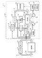
- FIG. 1 shows a configuration example of a cleaning apparatus 1 to which a liquid sample analyzer according to an embodiment of the present invention is applied.
- the cleaning apparatus 1 cleans a semiconductor wafer used in a semiconductor manufacturing process, and is configured to be able to measure the content of a focused substance (for example, ions) contained in a cleaning liquid.
- the cleaning device 1 includes a cleaning unit 11, a pump 12, a filter 13, and an analysis device 20.
- the cleaning device 1 further includes a circulation channel 14 that connects the cleaning unit 11, the pump 12, and the filter 13. That is, the cleaning unit 11, the pump 12, and the filter 13 are provided on the circulation channel 14.
- the circulation channel 14 is an annular channel through which the cleaning liquid LQ1 flows.
- the analyzer 20 corresponds to a specific example of “liquid sample analyzer” and “calibration device” of the present invention.
- the cleaning liquid LQ1 corresponds to a specific example of “first liquid sample” of the present invention.
- the cleaning unit 11 is for cleaning the semiconductor wafer. Specifically, the cleaning unit 11 cleans the semiconductor wafer using the cleaning liquid LQ1 supplied from the filter 13, and discharges the cleaning liquid LQ1 used for cleaning.
- the pump 12 sends the cleaning liquid LQ1 discharged from the cleaning unit 11 and used for cleaning to the filter 13.
- the filter 13 removes impurities such as dust contained in the supplied cleaning liquid LQ1. With this configuration, the cleaning liquid LQ1 used for cleaning in the cleaning unit 11 is removed of impurities by the filter 13, and is supplied to the cleaning unit 11 again. In this way, the cleaning liquid LQ1 circulates in the order of the cleaning unit 11, the pump 12, and the filter 13 and is reused.
- the cleaning liquid LQ1 used for cleaning often contains ions (for example, copper ions Cu 2+ ). Such ions are difficult to remove by the filter 13. Therefore, in the cleaning apparatus 1, the analyzer 20 samples the cleaning liquid LQ1 at a rate of once every 10 minutes, for example, and detects the amount of ions contained in the sampled cleaning liquid LQ1. Then, when the ion content exceeds a predetermined amount, the analyzer 20 prompts the control device (not shown) of the cleaning device 1 to replace the cleaning liquid LQ1.
- the analyzer 20 is provided to perform process management in the semiconductor manufacturing process.
- the analyzer 20 is a so-called flow cell type fluorescent X-ray analyzer.
- the analyzer 20 includes a valve 21, a deposition unit 22, a voltage generation unit 23, an X-ray source 24, a detection unit 25, a pump 26, a valve 27, a valve 28, and a control unit 29.
- the analyzer 20 further includes a connection channel 30, a circulation channel 31, and a discharge channel 32.
- the voltage generator 23 corresponds to a specific example of “power supply” of the present invention.
- the X-ray source 24 corresponds to a specific example of “X-ray source” of the present invention.
- the detection unit 25 corresponds to a specific example of “detection unit” of the present invention.
- the circulation channel 31 corresponds to a specific example of “a storage unit suitable for storing a liquid sample” of the present invention.
- connection flow path 30 one end is connected to the circulation flow path 14 and the other end is connected to the circulation flow path 31.
- the circulation channel 31 is an annular channel that connects the precipitation unit 22, the pump 26, and the valve 28.
- the discharge channel 32 is connected to the circulation channel 31.
- the valve 21 is provided on the connection channel 30, and specifically, provided at the end of the connection channel 30 on the circulation channel 31 side.
- the precipitation part 22, the pump 26 and the valve 28 are provided on the circulation channel 31.
- the valve 27 is provided on the discharge channel 32, and specifically, provided at the end of the discharge channel 32 on the circulation channel 31 side.
- the valve 21 is for sampling a part of the cleaning liquid LQ1 that circulates in the circulation flow path 14.
- the valve 21 controls communication between the circulation flow path 14 and the connection flow path 30 based on a control signal supplied from the control unit 29.
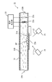
- FIG. 2 shows a configuration example of the precipitation part 22.
- a voltage generation unit 23, an X-ray source 24, and a detection unit 25 are drawn for convenience of explanation.
- the precipitation part 22 precipitates substances (for example, ions) contained in the cleaning liquid LQ1 flowing from the inlet 22A toward the outlet 22B.
- the deposition part 22 includes an electrode 22a, an electrode 22b, and a reference electrode 22c.
- the electrode 22a, the electrode 22b, and the reference electrode 22c are provided at predetermined positions in the circulation channel 31.
- the electrode 22a corresponds to a specific example of the “electrode” of the present invention.
- the electrode 22a is a conductive electrode having a property of transmitting X-rays, and deposits a substance (for example, ions) on the surface thereof.
- the electrode 22a is, for example, a thin film electrode.
- the electrode 22 a is provided so as to cover the opening 31 A provided on the wall surface of the circulation channel 31, and constitutes a part of the wall surface of the circulation channel 31.
- the electrode 22a may be provided in the circulation channel 31 at a position different from the wall surface of the circulation channel 31.
- a predetermined voltage (for example, a negative voltage) is applied to the electrode 22a by the voltage generator 23.
- cations for example, copper ions Cu 2+
- the cleaning liquid LQ1 when a negative voltage is applied to the electrode 22a, cations (for example, copper ions Cu 2+ ) contained in the cleaning liquid LQ1 are concentrated on and near the surface of the electrode 22a. Specifically, in the vicinity of the electrode 22a, the cation contained in the cleaning liquid LQ1 may have been attracted to the electrode 22a as an ion. Furthermore, cations contained in the cleaning liquid LQ1 are deposited on the surface of the electrode 22a.
- the cation concentration when a negative voltage is applied to the electrode 22a, the cation concentration is relatively high at and near the surface of the electrode 22a, and is relatively thin at locations away from the vicinity of the electrode 22a. Become.
- the concentrate DP when a negative voltage is applied to the electrode 22a, the cation attracted to the vicinity of the electrode 22a and the substance (precipitate) deposited on the surface of the electrode 22a are expressed as the concentrate DP.
- the X-ray L1 is irradiated from the X-ray source 24 to the electrode 22a.
- transmitted the electrode 22a is irradiated to the concentrate DP produced
- the concentrate DP corresponds to a specific example of the “concentrate”, “first concentrate”, and “second concentrate” of the present invention.
- the electrode 22a is preferably made of a material having high X-ray permeability and high chemical resistance.
- the electrode 22a is preferably composed of, for example, a diamond electrode, a glassy carbon electrode, or an electrode made of a conductive resin containing carbon.
- the electrode 22b is an electrode having a coil shape, and includes, for example, platinum. Due to this shape, the surface area of the electrode 22b is larger than the volume of the electrode 22b.
- the reference electrode 22c is an electrode used as a reference when a voltage is applied to the electrodes 22a and 22b, and is constituted by, for example, a so-called silver / silver chloride (Ag / AgCl) electrode.
- the electrode 22b and the reference electrode 22c are provided at positions away from the electrode 22a so that the X-ray L1 is not irradiated. Note that the reference electrode 22c may be omitted as necessary.
- the voltage generation unit 23 generates various voltages to be supplied to the deposition unit 22 based on a control signal supplied from the control unit 29. Specifically, the voltage generator 23 applies a predetermined voltage (for example, a negative voltage) to the electrode 22a with reference to the potential of the reference electrode 22c, and also applies a predetermined voltage (for example, a positive voltage) to the electrode 22b. ) Is applied. Thereby, in the precipitation part 22, for example, a part of cation (for example, copper ion Cu ⁇ 2+> ) contained in the washing
- a predetermined voltage for example, a negative voltage
- a predetermined voltage for example, a positive voltage
- the voltage generator 23 applies a positive voltage to the electrode 22a and a negative voltage to the electrode 22b after the analysis in the analyzer 20 is completed. Thereby, in the precipitation part 22, the concentrate DP elutes in the washing
- the X-ray source 24 emits X-rays L1 toward the electrode 22a.
- the X-ray source 24 can emit X-rays L1 toward the liquid in the circulation channel 31 as necessary.
- the X-ray source 24 irradiates the concentrate DP on the surface of the electrode 22a with the X-ray L1 via the electrode 22a.
- the X-ray source 24 operates based on a control signal supplied from the control unit 29.
- the X-ray source 24 is arranged on the side (the lower side in FIG. 3) where the electrode 22a is arranged as viewed from the circulation flow path 31.
- the X-ray source 24 is disposed at a position where the X-ray L1 passes through the electrode 22a and is irradiated on the concentrate DP.
- the detection unit 25 is configured using, for example, a semiconductor detector or a silicon drift detector (SDD). For example, as shown in FIG. 3, the detection unit 25 detects the fluorescent X-rays L2 emitted from the concentrate DP on the surface of the electrode 22a. In this example, the detection unit 25 is disposed on the side (the lower side in FIG. 3) where the electrode 22a is disposed as viewed from the circulation flow path 31.
- the detection unit 25 is disposed at a position where the fluorescent X-ray L2 emitted from the concentrate DP passes through the electrode 22a and enters the detection unit 25.
- the pump 26 circulates the cleaning liquid LQ1 by sending the cleaning liquid LQ1 flowing out from the outlet 22B of the precipitation part 22 to the introduction port 22A of the precipitation part 22.
- the pump 26 controls the circulation of the cleaning liquid LQ1 in the circulation channel 31 based on a control signal supplied from the control unit 29.
- the valve 27 is for discharging the cleaning liquid LQ1 that circulates in the circulation flow path 31.
- the valve 27 controls communication between the circulation flow path 31 and the discharge flow path 32 based on a control signal supplied from the control unit 29.
- the valve 28 closes the valve 28 when the cleaning liquid LQ1 is sampled from the circulation flow path 14, thereby making it difficult to discharge a part of the sampled cleaning liquid LQ1 to the discharge flow path 32.
- the control unit 29 controls operations of the valve 21, the voltage generation unit 23, the X-ray source 24, the pump 26 and the valve 27.
- the analyzing apparatus 20 further includes a storage unit 33, a measuring unit 34, and an adding device 35.
- the storage unit 33 corresponds to a specific example of “storage unit” and “recording medium” of the present invention.
- the measurement unit 34 corresponds to a specific example of “measurement unit” of the invention.
- the adding device 35 corresponds to a specific example of “adding unit” of the invention.
- a system including the deposition unit 22, the voltage generation unit 23, the X-ray source 24, the detection unit 25, the storage unit 33, and the measurement unit 34 corresponds to a specific example of “creation unit” and “measurement unit” of the present invention.
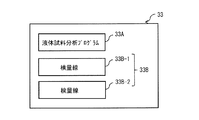
- the storage unit 33 stores, for example, a liquid sample analysis program 33A and a calibration curve 33B as shown in FIG.
- the calibration curve 33B corresponds to a specific example of “calibration information” of the present invention.
- the liquid sample analysis program 33A causes the processor of the analyzer 20 to perform a series of procedures for creating the calibration curve 33B and a series of procedures for calculating the concentration of the analysis target substance Sa in the standard solution LQ2 or the liquid sample LQ3. It is for execution.
- the analyzer 20 has a processor for executing a series of procedures described in the liquid sample analysis program 33A. In the analysis apparatus 20, the liquid sample analysis program 33A is loaded into the processor, whereby a series of procedures described in the liquid sample analysis program 33A is executed.
- the storage unit 33 is configured by a non-volatile memory, for example, an EEPROM, a flash memory, a resistance change type memory, or the like.
- the calibration curve 33B is a fluorescent X-ray of a concentrate DP (first concentrate) obtained by precipitation in a plurality of standard solutions LQ2 containing an internal standard substance Ss having a known concentration and an analysis target substance Sa having a known concentration. It was created based on analysis.
- the internal standard substance Ss corresponds to a specific example of the “internal standard substance” of the present invention.
- the analysis target substance Sa corresponds to a specific example of “analysis target substance” of the present invention.
- the standard solution LQ2 corresponds to a specific example of “standard solution” of the present invention.
- the internal standard substance Ss for example, a component that is not contained in the cleaning liquid LQ1 can be completely separated from the peak of the contaminating component, and the fluorescent X A line intensity peak appears, and a chemically and physically stable substance is selected.
- the analysis target substance Sa is copper ion Cu 2+
- scandium ion Sc 3+ is selected as the internal standard substance Ss.
- the calibration curve 33B has, for example, a calibration curve 33B-1 and a calibration curve 33B-2.
- the calibration curve 33B-1 corresponds to a specific example of “first calibration information” of the present invention.
- the calibration curve 33B-2 corresponds to a specific example of “second calibration information” of the present invention.
- Calibration curves 33B-1 and 33B-2 are functions obtained by the internal standard.
- the internal standard indicates that the internal standard substance Ss is mixed with the measurement sample containing the analysis target substance Sa and the internal standard substance Ss and the analysis target substance Sa are measured simultaneously.
- the calibration curve 33B-1 is included in the liquid before the concentrate DP is generated in the standard solution LQ2 and the fluorescent X-ray intensity ratio of the internal standard substance Ss and the analysis target substance Sa contained in the concentrate DP in the standard solution LQ2.
- the relationship between the internal standard substance Ss and the X-ray fluorescence intensity ratio of the analysis target substance Sa is expressed as a function.
- the calibration curve 33B-2 shows the ratio of the fluorescent X-ray intensity of the internal standard substance Ss and the analysis target substance Sa contained in the liquid before the concentrate DP is generated in the standard solution LQ2, and the concentrate DP is generated in the standard solution LQ2.
- the relationship between the concentration ratio of the internal standard substance Ss and the analysis target substance Sa contained in the liquid before being processed is expressed as a function.
- FIG. 5 is a schematic diagram illustrating a configuration example of the calibration curve 33B-2.
- the calibration curve 33B-2 is a multiple inspection calibration curve.
- the slope a and the intercept b are expressed by, for example, the following formulas (1) and (2).
- the 2-inspection calibration curve is a calibration curve derived based on fluorescent X-ray intensities obtained from two types of standard solutions LQ2 having different concentrations of the analysis target substance Sa. Since there are two measurement points in the 2-check quantity curve, the intercept b can take a value other than zero.
- the calibration curve 33B-2 is a calibration curve of three or more points, the calibration curve 33B-2 may be a broken line or a curve.
- M 1A is the concentration of the analysis target substance Sa in the first measurement sample containing the internal standard substance Ss and the analysis target substance Sa.
- M 2A is the concentration of the analysis target substance Sa in the second measurement sample containing the internal standard substance Ss and the analysis target substance Sa.
- M IS is the concentration of internal standard Ss in the first measurement sample and the second measurement sample.
- I 1A is the fluorescent X-ray intensity of the analysis target substance Sa in the first measurement sample.
- I 2A is the fluorescent X-ray intensity of the analysis target substance Sa in the second measurement sample.
- I IS is the fluorescent X-ray intensity of the internal standard substance Ss in the first measurement sample and the second measurement sample.
- the first measurement sample and the second measurement sample correspond to a specific example of “the liquid before the first concentrate is produced in the standard solution” of the present invention.
- FIG. 6 is a schematic diagram illustrating a configuration example of the calibration curve 33B-1.
- the calibration curve 33B-1 is a multiple inspection calibration curve.
- the slope a and the intercept b are expressed by the following equations (3) and (4), for example.
- the two inspection standard lines applied to the calibration curve 33B-1 are obtained from the concentrate DP deposited in the two types of standard solutions LQ2 used in deriving the two inspection standard curves applied to the calibration curve 33B-2. It is a calibration curve derived based on the obtained fluorescent X-ray intensity (first fluorescent X-ray intensity).
- the intercept b can take a value other than zero.
- the calibration curve 33B-1 is a calibration curve of three or more points, the calibration curve 33B-1 may be a broken line or a curve.
- I 3A is the fluorescent X-ray intensity of the analysis target substance Sa contained in the concentrate DP produced by precipitation in the first measurement sample.
- I 4A is a fluorescent X-ray intensity of the analyte Sa contained in concentrate DP produced by precipitation in the second measurement sample.
- I JS is the fluorescent X-ray intensity of the internal standard substance Ss contained in the concentrate DP produced by precipitation in the first measurement sample and the second measurement sample.
- the concentrate DP produced by precipitation in the first measurement sample and the concentrate DP produced by precipitation in the second measurement sample are specific examples of the “first concentrate in the standard solution” of the present invention. Corresponds to the example.
- the measurement unit 34 specifies a substance (for example, ion) contained in the cleaning liquid LQ1, the standard solution LQ2, or the liquid sample LQ3 based on the fluorescent X-ray L2 detected by the detection unit 25, and obtains the concentration of the specified substance. It is. As will be described later, the liquid sample LQ3 is created by adding the liquid sample LQ4 containing the internal standard substance Ss to the cleaning liquid LQ1.
- the liquid sample LQ3 corresponds to a specific example of “liquid sample” of the present invention.
- the liquid sample LQ4 corresponds to a specific example of “second liquid sample” of the present invention.
- the measurement unit 34 includes, for example, an amplifier, a pulse height analyzer, a multichannel analyzer, and the like. Moreover, the measurement part 34 has a function which notifies with respect to the control apparatus (not shown) of the washing
- the addition device 35 is a device that adds the liquid sample LQ4 containing the internal standard substance Ss to the liquid (cleaning liquid LQ1 or standard solution LQ2) flowing through the circulation flow path 31.
- the adding device 35 includes, for example, a discharge unit that discharges the liquid sample LQ4 to the circulation channel 31, a measurement unit that measures the concentration of the internal standard substance Ss contained in the liquid flowing through the circulation channel 31, and a measurement by the measurement unit. And a control unit for controlling the discharge amount from the discharge unit based on the result.
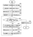
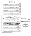
- FIG. 6 is a diagram illustrating an example of a calculation procedure of the concentration of the analysis target substance Ss in the cleaning liquid LQ1.
- the cleaning unit 11 cleans the semiconductor wafer using the cleaning liquid LQ1 supplied from the filter 13.
- the pump 12 sends the cleaning liquid LQ1 used for cleaning discharged from the cleaning unit 11 to the filter 13.
- the filter 13 removes impurities such as dust contained in the supplied cleaning liquid LQ1.
- the control unit 29 changes the valves 21 and 27 from the closed state to the open state. At this time, the control unit 29 maintains the valve 28 in a closed state.
- the circulation channel 14 and the circulation channel 31 communicate with each other via the connection channel 30, and a part of the cleaning liquid LQ 1 that circulates in the circulation channel 14 is supplied to the analyzer 20.
- the control unit 29 operates the pump 26. Accordingly, the cleaning liquid LQ1 flows in the order of the valve 21, the precipitation unit 22, the pump 26, and the valve 27. Thereafter, the control unit 29 opens the valve 28.
- the cleaning liquid LQ1 flows not only from the pump 26 toward the valve 27 but also toward the valve 28.
- the circulation channel 31 is filled with the cleaning liquid LQ1.
- the control unit 29 closes the valves 21 and 27. In this way, the control unit 29 samples the cleaning liquid LQ1 (step S101), and circulates the sampled cleaning liquid LQ1 in the output direction of the pump 26 in the circulation flow path 31.
- the adding device 35 adds the liquid sample LQ4 to the cleaning liquid LQ1 that flows through the circulation flow path 31 and contains the analyte Sa of unknown concentration, thereby adding the liquid sample LQ3 into the circulation flow path 31.
- the control unit 29 controls the opening and closing of the valve 27 so that the liquid sample LQ4 added by the adding device 35 is discharged from the circulation channel 31 by the volume.
- the adding device 35 supplies liquid to the cleaning liquid LQ1 flowing in the circulation channel 31 so that the concentration of the internal standard material Ss in the liquid sample LQ3 approaches the concentration of the internal standard material Ss in the standard solution LQ2.
- the liquid sample LQ3 is created in the circulation channel 31 by adding the sample LQ4.
- the concentration of the internal standard substance Ss in the liquid sample LQ3 preferably matches the concentration of the internal standard substance Ss in the standard solution LQ2, but does not exactly match the concentration of the internal standard substance Ss in the standard solution LQ2. Also good.
- the voltage generator 23 deposits the liquid sample LQ3 containing the internal standard substance Ss having a known concentration and the analysis target substance Sa having an unknown concentration (step S103). Specifically, the voltage generator 23 applies a predetermined voltage to the electrode 22a while the liquid sample LQ3 is circulating in the circulation channel 31 after the addition by the addition device 35 is stopped. The substances (internal standard substance Ss and analysis target substance Sa) contained in the liquid sample LQ3 in the circulation channel 31 are deposited on the electrode 22a. At this time, for example, the voltage generation unit 23 applies a negative voltage to the electrode 22a and a positive voltage to the electrode 22b with reference to the potential of the reference electrode 22c.
- the analyzer 20 performs fluorescent X-ray analysis on the concentrate DP obtained thereby (step S104). Thereby, the analyzer 20 obtains the fluorescent X-ray intensity (second fluorescent X-ray intensity) of the internal standard substance Ss and the analysis target substance Sa. Specifically, the X-ray source 24 emits X-rays L1 toward the concentrate DP on the surface of the electrode 22a, thereby generating fluorescent X-rays from the concentrate DP. The detector 25 detects the fluorescent X-ray L2 emitted from the concentrate DP on the surface of the electrode 22a.
- the measurement unit 34 measures the energy of the fluorescent X-ray L2 detected by the detection unit 25, and based on the energy of the fluorescent X-ray L2 obtained thereby, the substance (internal standard substance Ss and analysis) contained in the liquid sample LQ3
- the target substance Sa) is specified.
- the measuring unit 34 further measures the intensity of the fluorescent X-ray L2 detected by the detecting unit 25, and from the intensity of the fluorescent X-ray L2 obtained thereby, the fluorescent X of the identified internal standard substance Ss and the analysis target substance Sa. Identify the line strength.
- the measurement unit 34 further includes a fluorescent X-ray intensity of the internal standard substance Ss and the analysis target substance Sa obtained by the fluorescent X-ray analysis, a concentration (known concentration) of the internal standard substance Ss in the liquid sample LQ3, and a storage unit. Based on the calibration curve 33B read out from 33, the concentration of the analyte Sa in the liquid sample LQ3 is calculated (step S105).
- the measurement unit 34 uses the calibration curve 33B-2 included in the calibration curve 33B to calculate from the fluorescent X-ray intensity ratio between the internal standard substance Ss and the analysis target substance Sa contained in the concentrate DP in the liquid sample LQ3.
- the fluorescent X-ray intensity ratio between the internal standard substance Ss and the analysis target substance Sa contained in the liquid before the concentrate DP is generated in the liquid sample LQ3 is derived.
- the measurement unit 34 uses the calibration curve 33B-1 included in the calibration curve 33B to generate a concentrate DP in the liquid sample LQ3 from the fluorescent X-ray intensity ratio derived based on the calibration curve 33B-2.
- the concentration ratio of the internal standard substance Ss and the analysis target substance Sa contained in the previous liquid is derived.
- the measurement unit 34 calculates the concentration of the analysis target substance Sa in the liquid sample LQ3 by multiplying the derived concentration ratio by the concentration (known concentration) of the internal standard substance Ss in the liquid sample LQ3. .
- control unit 29 changes the valve 27 from the closed state to the open state.
- the liquid sample LQ3 is discharged from the circulation channel 31.
- the concentration obtained as described above was C LQ3, washing liquid
- the concentration C LQ1 of the analysis target substance Ss in LQ1 is expressed as follows. Accordingly, the measurement unit 34 calculates the concentration C LQ1 of the analysis target substance Ss in the cleaning liquid LQ1 using the following equation.
- C LQ1 C LQ3 ⁇ (V 1 + V 2 ) / V 1
- FIG. 8 is a diagram illustrating an example of a procedure for creating a calibration curve 33B (multiple inspection calibration curve).
- the control unit 29 closes the valve 21. Thereby, the circulation channel 31 is cut off from the circulation channel 14 (step S201).
- the adding device 35 discharges the standard solution LQ2 into the circulation channel 31, and fills the circulation channel 31 with the standard solution LQ2 (step S202).
- the analyzer 20 performs fluorescent X-ray analysis on the standard solution LQ2 (step S203). Thereby, the analyzer 20 obtains the fluorescent X-ray intensities of the internal standard substance Ss and the analysis target substance Sa included in the standard solution LQ2.
- the X-ray source 24 emits X-rays L1 toward the electrode 22a, thereby generating fluorescent X-rays from the standard solution LQ2.
- the detection unit 25 detects the fluorescent X-ray L2 emitted from the standard solution LQ2.
- the measurement unit 34 measures the energy of the fluorescent X-ray L2 detected by the detection unit 25, and based on the energy of the fluorescent X-ray L2 obtained thereby, the substance (internal standard substance Ss and analysis) contained in the standard solution LQ2
- the target substance Sa) is specified.
- the measuring unit 34 further measures the intensity of the fluorescent X-ray L2 detected by the detecting unit 25, and from the intensity of the fluorescent X-ray L2 obtained thereby, the fluorescent X of the identified internal standard substance Ss and the analysis target substance Sa. Identify the line strength.
- the measurement unit 34 stores the obtained fluorescent X-ray intensities of the internal standard substance Ss and the analysis target substance Sa and the concentrations of the internal standard substance Ss and the analysis target substance Sa in the standard solution LQ2 in the storage unit 33.
- the voltage generator 23 performs precipitation in the standard solution LQ2. Specifically, the voltage generation unit 23 applies a predetermined voltage to the electrode 22a while the standard solution LQ2 is circulating in the circulation channel 31 after the discharge by the addition device 35 is stopped. The substances (internal standard substance Ss and analysis target substance Sa) contained in the standard solution LQ2 in the circulation channel 31 are deposited on the electrode 22a. At this time, for example, the voltage generation unit 23 applies a negative voltage to the electrode 22a and a positive voltage to the electrode 22b with reference to the potential of the reference electrode 22c.
- the analyzer 20 performs fluorescent X-ray analysis on the concentrate DP obtained thereby (step S204). Thereby, the analyzer 20 obtains the fluorescent X-ray intensities of the internal standard substance Ss and the analysis target substance Sa. Specifically, the X-ray source 24 emits X-rays L1 toward the concentrate DP on the surface of the electrode 22a, thereby generating fluorescent X-rays from the concentrate DP. The detector 25 detects the fluorescent X-ray L2 emitted from the concentrate DP on the surface of the electrode 22a.
- the measurement unit 34 measures the energy of the fluorescent X-ray L2 detected by the detection unit 25, and based on the energy of the fluorescent X-ray L2 obtained thereby, the substance (internal standard substance Ss and analysis) contained in the standard solution LQ2
- the target substance Sa is specified.
- the measuring unit 34 further measures the intensity of the fluorescent X-ray L2 detected by the detecting unit 25, and from the intensity of the fluorescent X-ray L2 obtained thereby, the fluorescent X of the identified internal standard substance Ss and the analysis target substance Sa. Identify the line strength.
- the measurement unit 34 stores the obtained fluorescent X-ray intensities of the internal standard substance Ss and the analysis target substance Sa and the concentrations of the internal standard substance Ss and the analysis target substance Sa in the standard solution LQ2 in the storage unit 33. Thereafter, the voltage generator 23 applies a positive voltage to the electrode 22a and applies a negative voltage to the electrode 22b. Thereby, the concentrate DP on the surface of the electrode 22a is removed.
- the measurement unit 34 determines whether or not the fluorescent X-ray intensity and concentration have been acquired for all types of standard solutions LQ2 (all prepared types of standard solutions LQ2) having different concentrations of the analysis target substance Sa. (Step S205). When acquisition of fluorescent X-ray intensity and concentration is completed for all types (standard curve points) of standard solutions LQ2, the measurement unit 34 creates a calibration curve 33B (step S206). Specifically, the measurement unit 34 measures the fluorescence X-ray intensity of the internal standard substance Ss and the analysis target substance Sa obtained from the liquid before the concentrate DP is generated in each standard solution LQ2, and the standard solution LQ2.
- a calibration curve 33B-1 is created based on the internal standard substance Ss and the concentration of the analysis target substance Sa obtained from the liquid before the concentrate DP is generated. Further, the measuring unit 34 measures the fluorescent X-ray intensity of the internal standard substance Ss and the analysis target substance Sa obtained from the concentrate DP of each standard solution LQ2, and the liquid before the concentrate DP is generated in each standard solution LQ2.
- a calibration curve 33B-2 is created based on the internal standard substance Ss and the concentration of the analysis target substance Sa obtained from the above. The measuring unit 34 stores the created calibration curves 33B-1 and 33B-2 in the storage unit 33. Thereafter, the voltage generator 23 applies a positive voltage to the electrode 22a and applies a negative voltage to the electrode 22b. Thereby, the concentrate DP on the surface of the electrode 22a is removed. Thereafter, the control unit 29 changes the valve 27 from the closed state to the open state. As a result, the liquid sample LQ3 is discharged from the circulation channel 31.
- the addition device 35 creates a new standard solution LQ2. Specifically, the addition device 35 adds the liquid sample LQ4 (addition solution) containing the internal standard substance Ss and the analysis target substance Sa into the circulation channel 31, so that the concentration of the internal standard substance Ss is constant. A new standard solution LQ2 having a different concentration of the analysis target substance Sa is prepared (step S207). The adding device 35 sequentially supplies a plurality of types of standard solutions LQ2 having different concentrations of the analysis target substance Sa until the fluorescent X-ray intensity and concentration are obtained for all types (standard curve points) of the standard solutions LQ2. ,create.
- the concentration of the analysis target substance Sa is slightly higher than the concentration of the analysis target substance Sa contained in the standard solution LQ2 before the liquid sample LQ4 is added. Further, since the addition device 35 measures the concentration of the analysis target substance Sa contained in the newly prepared standard solution LQ2, the concentration of the analysis target substance Sa contained in the newly prepared standard solution LQ2 is Known. In the newly prepared standard solution LQ2, the concentration of the internal standard substance Ss is substantially equal to the concentration of the analysis target substance Sa contained in the standard solution LQ2 before the liquid sample LQ4 is added.
- the analyzer 20 performs fluorescent X-ray analysis on the newly prepared standard solution LQ2 (step S208). Thereby, the analyzer 20 obtains the fluorescent X-ray intensities of the internal standard substance Ss and the analysis target substance Sa included in the newly created standard solution LQ2.
- the measurement unit 34 stores the obtained fluorescent X-ray intensities of the internal standard substance Ss and the analysis target substance Sa and the concentrations of the internal standard substance Ss and the analysis target substance Sa in the standard solution LQ2 in the storage unit 33.
- the voltage generator 23 performs precipitation in the newly prepared standard solution LQ2. Specifically, after the addition by the addition device 35 is stopped, the voltage generator 23 applies a predetermined voltage to the electrode 22a while one kind of standard solution LQ2 is circulating in the circulation channel 31. By applying, the substances (internal standard substance Ss and analysis target substance Sa) contained in the standard solution LQ2 in the circulation channel 31 are deposited on the electrode 22a. At this time, for example, the voltage generation unit 23 applies a negative voltage to the electrode 22a and a positive voltage to the electrode 22b with reference to the potential of the reference electrode 22c.
- the analyzer 20 performs fluorescent X-ray analysis on the concentrate DP obtained thereby (step S209). Thereby, the analyzer 20 obtains the fluorescent X-ray intensities of the internal standard substance Ss and the analysis target substance Sa.
- the measurement unit 34 determines the fluorescent X-ray intensity of the internal standard substance Ss and the analysis target substance Sa obtained by the fluorescent X-ray analysis, and the concentrations of the internal standard substance Ss and the analysis target substance Sa in the newly prepared standard solution LQ2. (Known concentration) is stored in the storage unit 33.
- the voltage generator 23 applies a positive voltage to the electrode 22a and applies a negative voltage to the electrode 22b. Thereby, the concentrate DP on the surface of the electrode 22a is removed. In this way, the fluorescent X-ray intensity and concentration are acquired for all types of standard solutions LQ2. As a result, step S206 described above is performed.
- the precipitation is performed in the standard solution LQ2, and the X-ray fluorescence analysis is performed on the resulting concentrate DP, thereby obtaining the X-ray fluorescence intensities of the internal standard substance Ss and the analysis target substance Sa. It is done.
- the concentration of the analysis target substance Sa in the liquid sample LQ3 is calculated.
- the calibration curve 33B considering not only the concentration of the substance contained in the standard solution LQ2 but also the precipitation is used for calculating the concentration of the analysis target substance Sa in the liquid sample LQ3. Therefore, the analysis accuracy in the fluorescent X-ray analysis can be increased.
- the deposit DP is repeatedly attached and detached on the surface of the electrode 22a. Therefore, when the electrode 22a is used for a long time, the surface of the electrode 22a may be deteriorated such as rough.
- the ratio of the internal standard substance Ss and the analysis target substance Sa contained in the concentrate DP is theoretically almost independent of the deterioration of the surface of the electrode 22a. Therefore, even when the electrode 22a continues to be used for a long period of time and the calibration curve 33B continues to be used without being recreated, the analysis accuracy in the fluorescent X-ray analysis is almost the same as the initial. Therefore, in this embodiment, the analysis accuracy in the fluorescent X-ray analysis can be maintained high over a long period.
- the calibration curve 33B-1 generates the concentrate DP in the standard solution LQ2 and the fluorescent X-ray intensity ratio of the internal standard substance Ss and the analysis target substance Sa contained in the concentrate DP in the standard solution LQ2.
- the relationship between the internal standard substance Ss and the fluorescent substance X-ray intensity ratio of the analysis target substance Sa contained in the liquid after being expressed as a function may be used.
- the calibration curve 33B-2 shows that the fluorescent X-ray intensity ratio of the internal standard substance Ss and the analysis target substance Sa contained in the liquid after the concentrate DP is generated in the standard solution LQ2, and the concentrate DP in the standard solution LQ2.
- the relationship between the concentration ratio of the internal standard substance Ss and the analysis target substance Sa contained in the liquid before is generated may be expressed as a function.
- I 1A represents the fluorescence of the analyte Sa, which is contained in the liquid after the concentrate DP is generated in the first measurement sample. It is the X-ray intensity
- I 2A is the fluorescent X-ray intensity of the analysis target substance Sa contained in the liquid after the concentrate DP is generated in the second measurement sample.
- the calibration curve 33B-1 corresponds to a specific example of “third calibration information” of the present invention
- the calibration curve 33B-2 represents “fourth calibration information” of the present invention. This corresponds to a specific example.
- the measurement unit 34 uses the calibration curve 33B-1 included in the calibration curve 33B to use the internal standard substance Ss and the analysis target substance Sa included in the concentrate DP in the liquid sample LQ3. From the fluorescent X-ray intensity ratio, the fluorescent X-ray intensity ratio of the internal standard substance Ss and the analysis target substance Sa contained in the liquid after the concentrate DP is generated in the liquid sample LQ3 is derived. Further, the measurement unit 34 uses the calibration curve 33B-2 included in the calibration curve 33B to generate the concentrate DP in the liquid sample LQ3 from the fluorescent X-ray intensity ratio derived based on the calibration curve 33B-1. The concentration ratio of the internal standard substance Ss and the analysis target substance Sa contained in the previous liquid is derived. Finally, the measurement unit 34 calculates the concentration of the analysis target substance Sa in the liquid sample LQ3 by multiplying the derived concentration ratio by the concentration (known concentration) of the internal standard substance Ss in the liquid sample LQ3. .
- FIG. 9 is a diagram illustrating an example of a procedure for creating a calibration curve 33B (multiple inspection curve) in the present modification.
- the control unit 29 closes the valve 21. Thereby, the circulation channel 31 is separated from the circulation channel 14 (step S301).
- the adding device 35 discharges the standard solution LQ2 into the circulation channel 31, and fills the circulation channel 31 with the standard solution LQ2 (step S302).
- the voltage generation unit 23 performs precipitation in the standard solution LQ2. Specifically, the voltage generation unit 23 applies a predetermined voltage to the electrode 22a while the standard solution LQ2 is circulating in the circulation channel 31 after the discharge by the addition device 35 is stopped.
- the substances (internal standard substance Ss and analysis target substance Sa) contained in the standard solution LQ2 in the circulation channel 31 are deposited on the electrode 22a. At this time, for example, the voltage generation unit 23 applies a negative voltage to the electrode 22a and a positive voltage to the electrode 22b with reference to the potential of the reference electrode 22c.
- the analyzer 20 performs fluorescent X-ray analysis on the concentrate DP obtained thereby (step S303). Thereby, the analyzer 20 obtains the fluorescent X-ray intensities of the internal standard substance Ss and the analysis target substance Sa in the concentrate DP. Subsequently, the analyzer 20 performs fluorescent X-ray analysis on the liquid (hereinafter referred to as “liquid ⁇ ”) after the concentrate DP is generated in the standard solution LQ2 (step S304). Thereby, the analyzer 20 obtains the fluorescent X-ray intensities of the internal standard substance Ss and the analysis target substance Sa in the liquid ⁇ .
- the X-ray source 24 emits X-rays L1 toward the liquid ⁇ , thereby generating fluorescent X-rays from the liquid ⁇ .
- the detection unit 25 detects the fluorescent X-ray L2 emitted from the liquid ⁇ .
- the measurement unit 34 measures the energy of the fluorescent X-ray L2 detected by the detection unit 25, and based on the energy of the fluorescent X-ray L2 obtained thereby, the substance (internal standard substance Ss and analysis) contained in the standard solution LQ2
- the target substance Sa) is specified.
- the measuring unit 34 further measures the intensity of the fluorescent X-ray L2 detected by the detecting unit 25, and from the intensity of the fluorescent X-ray L2 obtained thereby, the fluorescent X of the identified internal standard substance Ss and the analysis target substance Sa. Identify the line strength.
- the measuring unit 34 measures the fluorescent X-ray intensity of the internal standard substance Ss and the analysis target substance Sa in the concentrate DP, the fluorescent X-ray intensity of the internal standard substance Ss and the analysis target substance Sa in the liquid ⁇ , and the standard solution LQ2 before precipitation.
- the concentration of the internal standard substance Ss and the analysis target substance Sa in is stored in the storage unit 33. Thereafter, the voltage generator 23 applies a positive voltage to the electrode 22a and applies a negative voltage to the electrode 22b. Thereby, the concentrate DP on the surface of the electrode 22a is removed.
- the measurement unit 34 determines whether or not the fluorescent X-ray intensity and concentration have been acquired for all types of standard solutions LQ2 (all prepared types of standard solutions LQ2) having different concentrations of the analysis target substance Sa. (Step S305).
- the measurement unit 34 creates a calibration curve 33B (step S306). Specifically, the measuring unit 34 measures the fluorescence X-ray intensity of the internal standard substance Ss and the analysis target substance Sa obtained from the liquid (liquid ⁇ ) after the concentrate DP is generated in each standard solution LQ2.
- a calibration curve 33B-1 is created based on the internal standard substance Ss and the concentration of the analysis target substance Sa obtained from the liquid before the concentrate DP is generated in the standard solution LQ2. Furthermore, the measuring unit 34 measures the fluorescence X-ray intensity of the internal standard substance Ss and the analysis target substance Sa obtained from the concentrate DP of each standard solution LQ2, and the liquid after the concentrate DP is generated in each standard solution LQ2.
- a calibration curve 33B-2 is created based on the internal standard substance Ss obtained from (liquid ⁇ ) and the concentration of the analysis target substance Sa. The measuring unit 34 stores the created calibration curves 33B-1 and 33B-2 in the storage unit 33. Thereafter, the voltage generator 23 applies a positive voltage to the electrode 22a and applies a negative voltage to the electrode 22b. Thereby, the concentrate DP on the surface of the electrode 22a is removed. Thereafter, the control unit 29 changes the valve 27 from the closed state to the open state. As a result, the liquid sample LQ3 is discharged from the circulation channel 31.
- the addition device 35 creates a new standard solution LQ2. Specifically, the addition device 35 adds the liquid sample LQ4 (addition solution) containing the internal standard substance Ss and the analysis target substance Sa into the circulation channel 31, so that the concentration of the internal standard substance Ss is constant. A new standard solution LQ2 having a different concentration of the analyte Sa is prepared (step S307). The adding device 35 sequentially supplies a plurality of types of standard solutions LQ2 having different concentrations of the analysis target substance Sa until the fluorescent X-ray intensity and concentration are obtained for all types (standard curve points) of the standard solutions LQ2. ,create.
- the concentration of the analysis target substance Sa is slightly higher than the concentration of the analysis target substance Sa contained in the standard solution LQ2 before the liquid sample LQ4 is added. Further, since the addition device 35 measures the concentration of the analysis target substance Sa contained in the newly prepared standard solution LQ2, the concentration of the analysis target substance Sa contained in the newly prepared standard solution LQ2 is Known. In the newly prepared standard solution LQ2, the concentration of the internal standard substance Ss is substantially equal to the concentration of the analysis target substance Sa contained in the standard solution LQ2 before the liquid sample LQ4 is added.
- the analyzer 20 performs precipitation on the newly prepared standard solution LQ2, and performs fluorescent X-ray analysis on the concentrate DP obtained thereby (step S308).
- the analyzer 20 obtains the fluorescent X-ray intensities of the internal standard substance Ss and the analysis target substance Sa contained in the concentrate DP generated with the newly prepared standard solution LQ2.
- the analyzer 20 performs fluorescent X-ray analysis on the liquid (liquid ⁇ ) after the concentrate DP is generated in the standard solution LQ2 (step S309).
- the analyzer 20 obtains the fluorescent X-ray intensities of the internal standard substance Ss and the analysis target substance Sa contained in the newly created liquid ⁇ .
- the measuring unit 34 measures the fluorescence X-ray intensity of the internal standard substance Ss and the analysis target substance Sa in the newly obtained concentrate DP, and the fluorescence X of the internal standard substance Ss and the analysis target substance Sa in the newly obtained liquid ⁇ .
- the line intensity and the concentrations of the internal standard substance Ss and the analysis target substance Sa in the newly generated standard solution LQ2 before precipitation are stored in the storage unit 33.
- the voltage generator 23 applies a positive voltage to the electrode 22a and applies a negative voltage to the electrode 22b.
- the concentrate DP on the surface of the electrode 22a is removed. In this way, the fluorescent X-ray intensity and concentration are acquired for all types of standard solutions LQ2.
- step S306 described above is performed.
- the calibration curve 33B considering not only the concentration of the substance contained in the standard solution LQ2 but also the precipitation is used for calculating the concentration of the analysis target substance Sa in the liquid sample LQ3. . Therefore, the analysis accuracy in the fluorescent X-ray analysis can be increased. In addition, the analysis accuracy in the fluorescent X-ray analysis can be maintained high over a long period of time.
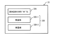
- the storage unit 33 may store a calibration curve 33D instead of the calibration curve 33B, for example, as shown in FIG.
- the calibration curve 33D corresponds to a specific example of “calibration information” of the present invention.
- the calibration curve 33D is a fluorescent X-ray of a concentrate DP (first concentrate) obtained by precipitation in a plurality of standard solutions LQ2 containing an internal standard substance Ss having a known concentration and an analysis target substance Sa having a known concentration. It was created based on analysis.
- the calibration curve 33D has, for example, a calibration curve 33D-1 and a calibration curve 33D-2.
- the calibration curve 33D-1 corresponds to a specific example of “fifth calibration information” of the present invention.
- the calibration curve 33D-2 corresponds to a specific example of “sixth calibration information” of the present invention.
- Calibration curves 33D-1 and 33D-2 are functions obtained by the internal standard.
- the calibration curve 33D-1 shows the X-ray fluorescence intensity ratio between the internal standard substance Ss and the analysis target substance Sa contained in the concentrate DP in the standard solution LQ2, and the internal standard substance Ss and analysis contained in the concentrate DP in the standard solution LQ2. It represents the relationship with the target substance Sa concentration ratio as a function.
- the calibration curve 33D-2 shows the concentration ratio of the internal standard substance Ss and the analysis target substance Sa contained in the concentrate DP in the standard solution LQ2, and the internal standard substance contained in the liquid before the concentrate DP is generated in the standard solution LQ2. The relationship between Ss and the concentration ratio of the substance to be analyzed Sa is expressed as a function.
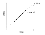
- FIG. 11 is a schematic diagram illustrating a configuration example of the calibration curve 33D-2.
- Calibration curve 33D-2 is a multiple inspection curve.
- the slope e and the intercept f are expressed by, for example, the following equations (5) and (6).
- the calibration curve 33D-2 is a calibration curve of three or more points, the calibration curve 33D-2 may be a broken line or a curve.
- M 1A is the concentration of the analysis target substance Sa in the first measurement sample containing the internal standard substance Ss and the analysis target substance Sa.
- M 2A is the concentration of the analysis target substance Sa in the second measurement sample containing the internal standard substance Ss and the analysis target substance Sa.
- M IS is the concentration of internal standard Ss in the first measurement sample and the second measurement sample.
- M 3A is the concentration of the analysis target substance Sa in the concentrate DP produced by precipitation in the first measurement sample.
- M 4A is the concentration of the analyte Sa in the concentrate DP generated by precipitation in the second measurement sample.
- M JS is the concentration of the internal standard substance Ss in the concentrate DP produced by precipitation in the first measurement sample and the second measurement sample.
- FIG. 12 is a schematic diagram illustrating a configuration example of the calibration curve 33D-1.
- the calibration curve 33D-1 is a multiple inspection calibration curve.
- the slope g and the intercept h are expressed by the following equations (7) and (8), for example.
- the calibration curve 33D-1 is a calibration curve of three or more points, the calibration curve 33D-1 may be a broken line or a curve.
- I 3A is the fluorescent X-ray intensity of the analysis target substance Sa in the concentrate DP generated by precipitation in the first measurement sample.
- I 4A is the fluorescent X-ray intensity of the analyte Sa in the concentrate DP generated by precipitation in the second measurement sample.
- I JS is the fluorescent X-ray intensity of the internal standard substance Ss in the concentrate DP produced by precipitation in the first measurement sample and the second measurement sample.
- the measurement unit 34 uses the calibration curve 33D-2 included in the calibration curve 33D to use the internal standard substance Ss and the analysis target substance Sa included in the concentrate DP in the liquid sample LQ3. From the fluorescent X-ray intensity ratio, the concentration ratio of the internal standard substance Ss and the analysis target substance Sa contained in the concentrate DP in the liquid sample LQ3 is derived. The measurement unit 34 further uses the calibration curve 33D-1 included in the calibration curve 33D to calculate the liquid before the concentrate DP is generated in the liquid sample LQ3 from the concentration ratio derived based on the calibration curve 33D-2. The concentration ratio between the internal standard substance Ss and the analysis target substance Sa contained in the sample is derived. Finally, the measurement unit 34 calculates the concentration of the analysis target substance Sa in the liquid sample LQ3 by multiplying the derived concentration ratio by the concentration (known concentration) of the internal standard substance Ss in the liquid sample LQ3. .
- FIG. 13 is a diagram illustrating an example of a procedure for creating a calibration curve 33D (multiple inspection curve) in the present modification.
- the control unit 29 closes the valve 21. Thereby, the circulation channel 31 is cut off from the circulation channel 14 (step S401).
- the adding device 35 discharges the standard solution LQ2 into the circulation channel 31, and fills the circulation channel 31 with the standard solution LQ2 (step S402).
- the voltage generation unit 23 performs precipitation in the standard solution LQ2. Specifically, the voltage generation unit 23 applies a predetermined voltage to the electrode 22a while the standard solution LQ2 is circulating in the circulation channel 31 after the discharge by the addition device 35 is stopped.
- the substances (internal standard substance Ss and analysis target substance Sa) contained in the standard solution LQ2 in the circulation channel 31 are deposited on the electrode 22a. At this time, for example, the voltage generation unit 23 applies a negative voltage to the electrode 22a and a positive voltage to the electrode 22b with reference to the potential of the reference electrode 22c.
- the analyzer 20 performs fluorescent X-ray analysis on the concentrate DP obtained thereby (step S403). Thereby, the analyzer 20 obtains the fluorescent X-ray intensities of the internal standard substance Ss and the analysis target substance Sa in the concentrate DP. Subsequently, the analyzer 20 performs concentration analysis on the concentrate DP in the standard solution LQ2 (step S404). Thereby, the analyzer 20 obtains the concentrations of the internal standard substance Ss and the analysis target substance Sa in the concentrate DP.
- the measuring unit 34 measures the fluorescent X-ray intensity of the internal standard substance Ss and the analysis target substance Sa in the concentrate DP, the concentration of the internal standard substance Ss and the analysis target substance Sa in the concentrate DP, and the internal concentration in the standard solution LQ2 before precipitation.
- the standard substance Ss and the concentration of the analysis target substance Sa are stored in the storage unit 33. Thereafter, the voltage generator 23 applies a positive voltage to the electrode 22a and applies a negative voltage to the electrode 22b. Thereby, the concentrate DP on the surface of the electrode 22a is removed.
- the measurement unit 34 determines whether or not the fluorescent X-ray intensity and concentration have been acquired for all types of standard solutions LQ2 (all prepared types of standard solutions LQ2) having different concentrations of the analysis target substance Sa. (Step S405).
- the measurement unit 34 creates a calibration curve 33D (step S406). Specifically, the measuring unit 34 measures the concentration of the internal standard substance Ss and the analysis target substance Sa obtained from the concentrate DP in each standard solution LQ2, and the liquid before the concentrate DP is generated in each standard solution LQ2.
- a calibration curve 33D-2 is created based on the concentrations of the internal standard substance Ss and the analysis target substance Sa obtained from the above.
- the measuring unit 34 measures the fluorescent X-ray intensity of the internal standard substance Ss and the analysis target substance Sa obtained from the concentrate DP of each standard solution LQ2, and the internal standard substance obtained from the concentrate DP in each standard solution LQ2.
- a calibration curve 33D-1 is created based on Ss and the concentration of the analysis target substance Sa.
- the measuring unit 34 stores the created calibration curves 33D-1 and 33D-2 in the storage unit 33.
- the voltage generator 23 applies a positive voltage to the electrode 22a and applies a negative voltage to the electrode 22b.
- the concentrate DP on the surface of the electrode 22a is removed.
- the control unit 29 changes the valve 27 from the closed state to the open state. As a result, the liquid sample LQ3 is discharged from the circulation channel 31.
- the addition device 35 creates a new standard solution LQ2. Specifically, the addition device 35 adds the liquid sample LQ4 (addition solution) containing the internal standard substance Ss and the analysis target substance Sa into the circulation channel 31, so that the concentration of the internal standard substance Ss is constant. A new standard solution LQ2 having a different concentration of the analysis target substance Sa is prepared (step S407). The adding device 35 sequentially supplies a plurality of types of standard solutions LQ2 having different concentrations of the analysis target substance Sa until the fluorescent X-ray intensity and concentration are obtained for all types (standard curve points) of the standard solutions LQ2. ,create.
- the concentration of the analysis target substance Sa is slightly higher than the concentration of the analysis target substance Sa contained in the standard solution LQ2 before the liquid sample LQ4 is added. Further, since the addition device 35 measures the concentration of the analysis target substance Sa contained in the newly prepared standard solution LQ2, the concentration of the analysis target substance Sa contained in the newly prepared standard solution LQ2 is Known. In the newly prepared standard solution LQ2, the concentration of the internal standard substance Ss is substantially equal to the concentration of the analysis target substance Sa contained in the standard solution LQ2 before the liquid sample LQ4 is added.
- the analyzer 20 performs precipitation on the newly prepared standard solution LQ2, and performs fluorescent X-ray analysis on the concentrate DP obtained thereby (step S408). Thereby, the analyzer 20 obtains the fluorescent X-ray intensities of the internal standard substance Ss and the analysis target substance Sa in the concentrate DP generated by the newly prepared standard solution LQ2. Subsequently, the analyzer 20 performs a concentration analysis on the concentrate DP in the standard solution LQ2 (step S409). Thereby, the analyzer 20 obtains the concentrations of the internal standard substance Ss and the analysis target substance Sa in the newly created concentrate DP.
- the measuring unit 34 measures the fluorescent X-ray intensities of the internal standard substance Ss and the analysis target substance Sa in the newly obtained concentrate DP, and the concentrations of the internal standard substance Ss and the analysis target substance Sa in the newly obtained concentrate DP. And the concentrations of the internal standard substance Ss and the analysis target substance Sa in the newly generated standard solution LQ2 before precipitation are stored in the storage unit 33. Thereafter, the voltage generator 23 applies a positive voltage to the electrode 22a and applies a negative voltage to the electrode 22b. Thereby, the concentrate DP on the surface of the electrode 22a is removed. In this way, the fluorescent X-ray intensity and concentration are acquired for all types of standard solutions LQ2. As a result, step S406 described above is performed.
- the calibration curve 33D considering not only the concentration of the substance contained in the standard solution LQ2 but also the precipitation is used for calculating the concentration of the analyte Sa in the liquid sample LQ3. . Therefore, the analysis accuracy in the fluorescent X-ray analysis can be increased. In addition, the analysis accuracy in the fluorescent X-ray analysis can be maintained high over a long period of time.
- the calibration curves 33B and 33D are used for calculating the concentration of the analysis target substance Sa in the liquid sample LQ3.
- a calibration table 33C in which the calibration curves 33B and 33D are represented by a table may be created instead of the calibration curves 33B and 33D.
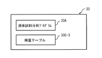
- a calibration table 33C in which the calibration curves 33B and 33D are represented by a table indicates the concentration of the analyte Sa in the liquid sample LQ3. It may be used for calculation. In this case, for example, as shown in FIG.
- the storage unit 33 stores a calibration table 33C instead of the calibration curves 33B and 33D.
- the calibration table 33C includes, for example, a calibration table 33C-1 corresponding to the calibration curves 33B-1 and 33D-1, and a calibration table 33C-2 corresponding to the calibration curves 33B-2 and 33D-2.
- the calibration table 33C corresponds to a specific example of “calibration information” of the present invention.
- the calibration table 33C-1 corresponds to a specific example of “first calibration information” of the present invention
- the calibration table 33C-2 corresponds to a specific example of “second calibration information” of the present invention.
- a calibration table 33C that plays the same role as the calibration curves 33B and 33D is used to calculate the concentration of the analysis target substance Sa in the liquid sample LQ3. Therefore, the same effect as the above embodiment can be obtained.
- the X-ray source 24 was illustrated as a supply source of the X-ray which irradiates the concentrate DP.
- the analyzer 20 has a secondary target in the circulation channel 31, and the X-ray source 24 emits X-rays toward the secondary target. Also good.
- the X-ray source 24 and the secondary target are configured such that X-rays generated from the secondary target irradiate the concentrate DP. Even in this case, the same effect as the above embodiment can be obtained.
- the circulation flow path 14 and the circulation flow path 31 are provided separately from each other.
- the circulation channel 14 may also serve as the circulation channel 31.
- a part of the component of the electrode 22a in the precipitation part 22 may be dissolved in the cleaning liquid LQ1.
- the internal standard substance Ss contained in the liquid sample LQ4 discharged from the adding device 35 is dissolved in the cleaning liquid LQ1. Therefore, in the configuration in which the circulation channel 14 also serves as the circulation channel 31, a part of the components of the electrode 22a dissolves in the cleaning liquid LQ1, or the internal standard substance Ss contained in the liquid sample LQ4 dissolves in the cleaning liquid LQ1. It can be applied to non-problematic uses.
- the analyzer 20 is applied to the cleaning device 1 and detects ions contained in the cleaning liquid LQ1.
- the analyzer 20 is not limited to this application, and can be applied to various applications that need to detect a small amount of ions.
- the analyzer 20 may detect ions contained in an etching solution used when etching is performed in a semiconductor manufacturing process, for example.
- the X-ray source 24 and the detection unit 25 are arranged on the side (the lower side in FIG. 3) where the electrode 22a is arranged as viewed from the circulation flow path 31.
- at least one of the X-ray source 24 and the detection unit 25 is opposite to the side on which the electrode 22a is disposed when viewed from the circulation channel 31. It may be arranged on the side (upper side in FIG. 3).
- the circulation flow path 31 in the precipitation part 22 has a cylindrical shape with a uniform diameter.
- the circulation flow path 31 in the precipitation part 22 is not limited to this.
- the circulation flow path 31 in the precipitation part 22 may be provided with the constriction part in the location corresponding to the electrode 22a, for example.
- the flow velocity in the circulation channel 31 in the precipitation part 22 is accelerated by the constriction part. As a result, the deposition rate can be increased, and the analysis accuracy in the fluorescent X-ray analysis can be increased.
- the reference electrode 22c is provided. However, in the above-described embodiment and its modification, the reference electrode 22c may be omitted when the influence on the analysis accuracy in the fluorescent X-ray analysis is small.
- one analyzer 20 creates calibration information (a calibration curve 33B, a calibration curve 33D, or a calibration table 33C) and measures the concentration of the analysis target substance Sa in the liquid sample LQ3. I was supposed to do it.
- the analyzer 20 that creates calibration information (a calibration curve 33B, a calibration curve 33D, or a calibration table 33C) and an analyzer that measures the concentration of the analyte Sa in the liquid sample LQ3. 20 may be separate devices.
- the master analyzer 20 creates calibration information (a calibration curve 33B, a calibration curve 33D, or a calibration table 33C) and stores it in the storage unit 33 of the analyzer 20 that is shipped to the user. May store calibration information (a calibration curve 33B, a calibration curve 33D, or a calibration table 33C) created by the master analyzer 20.
- the calibration information can be stored in the storage unit 33 before the cleaning device 1 is shipped to the user, the user can The cleaning device 1 can be used immediately after arrival.
- the storage unit 33 has two calibration curves or two calibration tables.
- the storage unit 33 may store, for example, one calibration curve 33B-3, one calibration curve 33D-3, or one calibration table 33C as shown in FIGS. You may have only -3.
- the calibration curve 33B-3, the calibration curve 33D-3, or the calibration table 33C-3 corresponds to a specific example of “calibration information” of the present invention.
- the calibration curve 33B-3 is a calibration curve obtained by synthesizing two calibration curves 33B-1 and 33B-2.
- the calibration curve 33D-3 is a calibration curve obtained by synthesizing two calibration curves 33D-1 and 33D-2.
- the calibration curve 33B-3 and the calibration curve 33D-3 are respectively the fluorescence X-ray intensity ratios of the internal standard substance Ss and the analysis target substance Sa contained in the concentrate DP in the standard solution LQ2, and the standard solution LQ2. 4 represents the relationship between the concentration ratio of the internal standard substance Ss and the analysis target substance Sa contained in the liquid before the concentrate DP is generated as a function.
- the calibration table 33C-3 is a calibration curve obtained by combining two calibration tables 33C-1 and 33C-2. Specifically, the calibration table 33C-3 is a calibration table corresponding to the calibration curve 33B-3 or the calibration curve 33D-3. Even in this case, the same effect as the above embodiment can be obtained.
- this invention can be set as the following structures.
- a storage unit suitable for storing a liquid sample containing an internal standard substance with a known concentration and an analysis target substance with an unknown concentration An electrode provided in the housing portion; A power source for applying a voltage to the electrode; An X-ray source emitting X-rays toward the electrode; A storage unit for storing calibration information created based on a fluorescent X-ray analysis of a first concentrate in a standard solution containing an internal standard substance having a known concentration and an analysis target substance having a known concentration; A detection unit for detecting fluorescent X-rays emitted from the second concentrate generated on the electrode by voltage application from the power source; The fluorescent X-ray analysis of the second concentrate is performed to obtain the fluorescent X-ray intensities of the internal standard substance and the analysis target substance contained in the second concentrate, and then the obtained fluorescent X-ray is obtained.
- a liquid sample analyzer comprising: a measurement unit that calculates the unknown concentration based on line intensity, a known concentration of the internal standard substance contained in the liquid sample, and the calibration information.
- the calibration information is Fluorescence X-ray intensity ratio of the internal standard substance and the analyte substance contained in the first concentrate in the standard solution, and contained in the liquid before the first concentrate is generated in the standard solution.
- the liquid sample analyzer according to (1) which is calibration information representing a relationship between a concentration ratio of the internal standard substance and the analysis target substance.
- the calibration information is Fluorescence X-ray intensity ratio of the internal standard substance and the analyte substance contained in the first concentrate in the standard solution, and contained in the liquid before the first concentrate is generated in the standard solution
- First calibration information representing the relationship between the internal standard substance and the fluorescent X-ray intensity ratio of the analysis target substance;
- the fluorescent X-ray intensity ratio of the internal standard substance and the analyte substance contained in the liquid before the first concentrate is generated in the standard solution, and the first concentrate is generated in the standard solution.
- the liquid sample analyzer according to (1) further comprising: second calibration information representing a relationship between a concentration ratio of the internal standard substance and the analysis target substance contained in the liquid before the measurement.
- the calibration information is Fluorescent X-ray intensity ratio of the internal standard substance and the analyte substance contained in the first concentrate in the standard solution, and contained in the liquid after the first concentrate is generated in the standard solution
- Third calibration information representing the relationship between the internal standard substance and the fluorescent X-ray intensity ratio of the analysis target substance;
- the fluorescent X-ray intensity ratio of the internal standard substance and the analyte substance contained in the liquid after the first concentrate is generated in the standard solution, and the first concentrate is generated in the standard solution.
- the liquid sample analyzer according to (1) further comprising: fourth calibration information representing a relationship between a concentration ratio of the internal standard substance and the analysis target substance contained in the liquid before the measurement.
- the calibration information is Fluorescence X-ray intensity ratio of the internal standard substance and the analyte substance contained in the first concentrate in the standard solution, and the internal standard substance and the analysis contained in the first concentrate in the standard solution.
- Fifth calibration information representing the relationship with the concentration ratio of the target substance; A concentration ratio of the internal standard substance and the analyte substance contained in the first concentrate in the standard solution, and the internal standard contained in the liquid before the first concentrate is generated in the standard solution
- An addition unit for creating the liquid sample by adding the second liquid sample containing the internal standard substance to the first liquid sample containing the substance to be analyzed having an unknown concentration is further provided.
- the liquid sample analyzer according to any one of 5).
- the accommodating portion is a circulation channel,
- the power source applies the predetermined voltage to the electrode while the liquid sample is circulating in the circulation channel, thereby allowing the internal standard substance and the analysis target substance contained in the liquid sample to be
- the liquid sample analyzer according to any one of (1) to (6), wherein the liquid sample analyzer is deposited on an electrode.
- the X-ray source generates X-ray fluorescence from the second concentrate by emitting X-rays toward the second concentrate;
- the measurement unit specifies the substance contained in the second concentrate and its intensity by measuring the energy and intensity of the fluorescent X-rays generated from the second concentrate.
- (1) to (7) The liquid sample analyzer according to any one of the above.
- the calibration information is Fluorescence X-ray intensity ratio of the internal standard substance and the analyte substance contained in the first concentrate in the standard solution, and contained in the liquid before the first concentrate is generated in the standard solution
- First calibration information representing the relationship between the internal standard substance and the fluorescent X-ray intensity ratio of the analysis target substance;
- the fluorescent X-ray intensity ratio of the internal standard substance and the analyte substance contained in the liquid before the first concentrate is generated in the standard solution, and the first concentrate is generated in the standard solution.
- the calibration information is Fluorescent X-ray intensity ratio of the internal standard substance and the analyte substance contained in the first concentrate in the standard solution, and contained in the liquid after the first concentrate is generated in the standard solution
- Third calibration information representing the relationship between the internal standard substance and the fluorescent X-ray intensity ratio of the analysis target substance;
- the fluorescent X-ray intensity ratio of the internal standard substance and the analyte substance contained in the liquid after the first concentrate is generated in the standard solution, and the first concentrate is generated in the standard solution.
- the calibration information is Fluorescence X-ray intensity ratio of the internal standard substance and the analyte substance contained in the first concentrate in the standard solution, and the internal standard substance and the analysis contained in the first concentrate in the standard solution.
- Fifth calibration information representing the relationship with the concentration ratio of the target substance; A concentration ratio of the internal standard substance and the analyte substance contained in the first concentrate in the standard solution, and the internal standard contained in the liquid before the first concentrate is generated in the standard solution
- the liquid sample analyzer according to any one of 13).
- the preparation unit applies the predetermined voltage to the electrode while the standard solution is circulating in the circulation channel including the electrode, whereby the internal standard substance contained in the standard solution and the analysis are applied.
- the target substance is deposited on the electrode,
- the measurement unit applies the predetermined voltage to the electrode while the liquid sample is circulating in the circulation flow path, so that the internal standard substance and the analysis target substance contained in the liquid sample are obtained.
- the liquid sample analyzer according to any one of (9) to (14), wherein the liquid sample analyzer is deposited on the electrode.
- the preparation unit generates X-rays from the first concentrate by emitting X-rays toward the first concentrate, and energy of the fluorescent X-rays generated from the first concentrate. And measuring the strength and the substance contained in the first concentrate and its strength, The measurement unit emits X-rays toward the second concentrate to generate fluorescent X-rays from the second concentrate, and energy of the fluorescent X-rays generated from the second concentrate.
- the liquid sample analyzer according to any one of (9) to (15), wherein the substance contained in the second concentrate and the strength thereof are specified by measuring the strength and the strength.
- a fluorescent X-ray analysis is performed on a concentrate in a standard solution containing an internal standard substance having a known concentration and an analysis target substance having a known concentration, whereby fluorescence X of the internal standard substance and the analysis target substance contained in the concentrate is obtained.
- a calibration apparatus comprising a creation unit that creates calibration information based on the obtained fluorescent X-ray intensity after obtaining the line intensity.
- a fluorescent X-ray analysis is performed on a concentrate in a standard solution containing an internal standard substance having a known concentration and an analysis target substance having a known concentration, whereby fluorescence X of the internal standard substance and the analysis target substance contained in the concentrate is obtained.
- the calibration method includes creating calibration information based on the obtained fluorescent X-ray intensity.
- liquid sample analysis program 33B, 33B-1, 33B-2, 33B-3, 33D, 33D-1, 33D- 2 ... calibration curve, 33C, 33C-1, 33C-2, 33C-3 ... calibration table, 34 ... measurement unit, 35 ... addition device, a, c, e, g ... inclination, b, d, f, h ... sections, DP ... concentrate, I 1A ... first measurement sample odor X-ray fluorescence intensity of the analyte Sa contained in a liquid after being before or product concentrate DP is produced, after the previous or product concentrate DP is generated in the I 2A ... second measurement sample X-ray intensity of the analysis target substance Sa contained in the liquid, I 3A ...
- Fluorescence X-ray intensity of analysis target substance Sa in concentrate DP produced by precipitation in the sample I IS ... fluorescence X-ray intensity of internal standard substance Ss in the first measurement sample and second measurement sample, I JS ... Fluorescence X-ray intensity of the internal standard substance Ss in the concentrate DP produced by precipitation in the first measurement sample and the second measurement sample, L1... X-ray, L ... X-ray fluorescence, LQ1 ... cleaning liquid, LQ2 ... standard solution, LQ3, LQ4 ... liquid sample, M 1A ...
Landscapes
- Physics & Mathematics (AREA)
- Health & Medical Sciences (AREA)
- Life Sciences & Earth Sciences (AREA)
- Chemical & Material Sciences (AREA)
- Analytical Chemistry (AREA)
- Biochemistry (AREA)
- General Health & Medical Sciences (AREA)
- General Physics & Mathematics (AREA)
- Immunology (AREA)
- Pathology (AREA)
- Analysing Materials By The Use Of Radiation (AREA)
Abstract
液体試料分析装置は、記憶部、検出部および計測部を備えている。記憶部は、既知濃度の内標準物質と、既知濃度の分析対象物質とを含む標準溶液における第1の濃縮物の蛍光X線分析に基づいて作成された検量情報を格納している。検出部は、電源からの電圧印加によって電極上に生成する第2の濃縮物から放射される蛍光X線を検出する。計測部は、第2の濃縮物について蛍光X線分析を行うことにより、第2の濃縮物に含まれる内標準物質および分析対象物質の蛍光X線強度を得た後、得られた蛍光X線強度と、液体試料に含まれる内標準物質の既知濃度と、検量情報とに基づいて、未知濃度を算出する。
Description
本発明は、蛍光X線を利用して液体試料を分析する液体試料分析装置および液体試料分析方法に関する。また、本発明は、蛍光X線を利用して液体試料を分析するプログラムが格納された記録媒体に関する。また、本発明は、蛍光X線を利用した液体試料の分析に用いられるデータを校正する検量装置および検量方法に関する。
液体試料に含まれる物質やその濃度を分析する際、しばしば蛍光X線分析が用いられる。この蛍光X線分析では、物質によって蛍光X線のエネルギーが異なることを利用して、液体試料についての分析が行われる。例えば、特許文献1には、液体試料を流しながら、蛍光X線を用いて、その液体試料に含まれるイオンを検出する分析装置が開示されている。
ところで、蛍光X線分析では、測定された蛍光X線の強度から物質の濃度が特定される。例えば、特許文献2には、物質の濃度とX線強度との関数である検量線を用いて、測定されたX線強度から物質の濃度を特定するX線分析方法が開示されている。
一般に、分析装置では分析精度が高いことが望まれており、蛍光X線を利用して液体試料を分析する液体試料分析装置においても、分析精度の向上が期待されている。
本発明はかかる問題点に鑑みてなされたもので、その目的は、分析精度を高めることのできる液体試料分析装置、液体試料分析方法、記録媒体、検量装置および検量方法を提供することにある。
本発明の第1の液体試料分析装置は、収容部、電極、電源、X線源、記憶部、検出部および計測部を備えている。収容部は、既知濃度の内標準物質と、未知濃度の分析対象物質とを含む液体試料の収容に適したものである。電極は、収容部に設けられている。電源は、電極に電圧を印加するようになっている。X線源は、電極に向かってX線を射出するようになっている。記憶部は、既知濃度の内標準物質と、既知濃度の分析対象物質とを含む標準溶液における第1の濃縮物の蛍光X線分析に基づいて作成された検量情報を格納している。検出部は、電源からの電圧印加によって電極上に生成する第2の濃縮物から放射される蛍光X線を検出するようになっている。計測部は、第2の濃縮物について蛍光X線分析を行うことにより、第2の濃縮物に含まれる内標準物質および分析対象物質の蛍光X線強度を得た後、得られた蛍光X線強度と、液体試料に含まれる内標準物質の既知濃度と、検量情報とに基づいて、未知濃度を算出するようになっている。
本発明の第2の液体試料分析装置は、作成部と、計測部とを備えている。作成部は、既知濃度の内標準物質と、既知濃度の分析対象物質とを含む標準溶液における第1の濃縮物について蛍光X線分析を行うことにより、第1の濃縮物に含まれる内標準物質および分析対象物質の第1の蛍光X線強度を得た後、得られた第1の蛍光X線強度に基づいて検量情報を作成するようになっている。計測部は、既知濃度の前記内標準物質と、未知濃度の前記分析対象物質とを含む液体試料における第2の濃縮物について蛍光X線分析を行うことにより、第2の濃縮物に含まれる内標準物質および分析対象物質の第2の蛍光X線強度を得た後、得られた第2の蛍光X線強度と、液体試料に含まれる内標準物質の既知濃度と、検量情報とに基づいて、未知濃度を算出するようになっている。
本発明の液体試料分析方法は、以下の2つの手順((A1),(A2))を含むものである。
(A1)既知濃度の内標準物質と、既知濃度の分析対象物質とを含む標準溶液における第1の濃縮物について蛍光X線分析を行うことにより、第1の濃縮物に含まれる内標準物質および分析対象物質の第1の蛍光X線強度を得た後、得られた第1の蛍光X線強度に基づいて検量情報を作成すること
(A2)既知濃度の内標準物質と、未知濃度の分析対象物質とを含む液体試料における第2の濃縮物について蛍光X線分析を行うことにより、第2の濃縮物に含まれる内標準物質および分析対象物質の第2の蛍光X線強度を得た後、得られた第2の蛍光X線強度と、液体試料に含まれる内標準物質の既知濃度と、検量情報とに基づいて、未知濃度を算出すること
(A1)既知濃度の内標準物質と、既知濃度の分析対象物質とを含む標準溶液における第1の濃縮物について蛍光X線分析を行うことにより、第1の濃縮物に含まれる内標準物質および分析対象物質の第1の蛍光X線強度を得た後、得られた第1の蛍光X線強度に基づいて検量情報を作成すること
(A2)既知濃度の内標準物質と、未知濃度の分析対象物質とを含む液体試料における第2の濃縮物について蛍光X線分析を行うことにより、第2の濃縮物に含まれる内標準物質および分析対象物質の第2の蛍光X線強度を得た後、得られた第2の蛍光X線強度と、液体試料に含まれる内標準物質の既知濃度と、検量情報とに基づいて、未知濃度を算出すること
本発明の記録媒体は、以下の2つの手順((B1),(B2))をプロセッサに実現させるためのプログラムが格納されたものである。
(B1)既知濃度の内標準物質と、既知濃度の分析対象物質とを含む標準溶液における第1の濃縮物について蛍光X線分析を行うことにより、第1の濃縮物に含まれる内標準物質および分析対象物質の第1の蛍光X線強度を得た後、得られた第1の蛍光X線強度に基づいて検量情報を作成する作成部に対して、検量情報の作成を指示すること
(B2)既知濃度の内標準物質と、未知濃度の分析対象物質とを含む液体試料における第2の濃縮物について蛍光X線分析を行うことにより、第2の濃縮物に含まれる内標準物質および分析対象物質の第2の蛍光X線強度を得た後、得られた第2の蛍光X線強度と、液体試料に含まれる内標準物質の既知濃度と、検量情報とに基づいて、上記未知濃度を算出する計測部に対して、上記未知濃度の算出を指示すること
(B1)既知濃度の内標準物質と、既知濃度の分析対象物質とを含む標準溶液における第1の濃縮物について蛍光X線分析を行うことにより、第1の濃縮物に含まれる内標準物質および分析対象物質の第1の蛍光X線強度を得た後、得られた第1の蛍光X線強度に基づいて検量情報を作成する作成部に対して、検量情報の作成を指示すること
(B2)既知濃度の内標準物質と、未知濃度の分析対象物質とを含む液体試料における第2の濃縮物について蛍光X線分析を行うことにより、第2の濃縮物に含まれる内標準物質および分析対象物質の第2の蛍光X線強度を得た後、得られた第2の蛍光X線強度と、液体試料に含まれる内標準物質の既知濃度と、検量情報とに基づいて、上記未知濃度を算出する計測部に対して、上記未知濃度の算出を指示すること
本発明の検量装置は、作成部を備えている。作成部は、既知濃度の内標準物質と、既知濃度の分析対象物質とを含む標準溶液における濃縮物について蛍光X線分析を行うことにより、濃縮物に含まれる内標準物質および分析対象物質の蛍光X線強度を得た後、得られた蛍光X線強度に基づいて検量情報を作成するようになっている。
本発明の検量方法は、既知濃度の内標準物質と、既知濃度の分析対象物質とを含む標準溶液における濃縮物について蛍光X線分析を行うことにより、濃縮物に含まれる内標準物質および分析対象物質の蛍光X線強度を得た後、得られた蛍光X線強度に基づいて検量情報を作成することを含んでいる。
本発明の第1の液体試料分析装置、第2の液体試料分析装置、液体試料分析方法および記録媒体によれば、標準溶液に含まれる物質の濃度だけでなく析出まで考慮された検量情報を用いたので、分析精度を高めることができる。また、本発明の検量装置および検量方法によれば、標準溶液に含まれる物質の濃度だけでなく析出まで考慮された検量情報が作成されるので、そのようにして作成された検量情報を用いることにより分析精度を高めることができる。
以下、本発明の実施の形態について、図面を参照して詳細に説明する。なお、説明は以下の順序で行う。
1.実施の形態
濃度だけでなく析出まで考慮された検量線を用いた例
2.変形例
変形例A:検量線を別の方法で作成した例
変形例B:検量線を別の方法で作成した例
変形例C:複数点検量線の代わりに1点検量線を用いた例
変形例D:検量線の代わりに検量テーブルを用いた例
変形例E:X線の供給源として2次ターゲットを用いた例
変形例F:洗浄部を含む循環流路が析出部を含む循環流路を兼ねている例
変形例G:エッチング液に含まれるイオンの検出を行う例
変形例H:X線源および検出部の配置のバリエーション
変形例I:析出部における循環流路に狭窄部を設けた例
変形例J:基準電極が省略された例
変形例K:検量線の作成と、未知濃度の計測とを同一の分析装置で行う例
変形例L:合成検量線または合成検量テーブルを用いた例
1.実施の形態
濃度だけでなく析出まで考慮された検量線を用いた例
2.変形例
変形例A:検量線を別の方法で作成した例
変形例B:検量線を別の方法で作成した例
変形例C:複数点検量線の代わりに1点検量線を用いた例
変形例D:検量線の代わりに検量テーブルを用いた例
変形例E:X線の供給源として2次ターゲットを用いた例
変形例F:洗浄部を含む循環流路が析出部を含む循環流路を兼ねている例
変形例G:エッチング液に含まれるイオンの検出を行う例
変形例H:X線源および検出部の配置のバリエーション
変形例I:析出部における循環流路に狭窄部を設けた例
変形例J:基準電極が省略された例
変形例K:検量線の作成と、未知濃度の計測とを同一の分析装置で行う例
変形例L:合成検量線または合成検量テーブルを用いた例
<1.実施の形態>
[構成例]
図1は、本発明の一実施の形態に係る液体試料分析装置が適用された洗浄装置1の一構成例を表すものである。洗浄装置1は、この例では、半導体製造工程において用いられる半導体ウエハを洗浄するものであり、洗浄液に含まれる着目した物質(例えばイオン)の含有量を測定可能に構成されたものである。洗浄装置1は、洗浄部11、ポンプ12、フィルタ13および分析装置20を備えている。洗浄装置1は、さらに、洗浄部11、ポンプ12およびフィルタ13をつなぐ循環流路14を備えている。つまり、洗浄部11、ポンプ12およびフィルタ13は、循環流路14上に設けられている。循環流路14は、洗浄液LQ1が流れる環状の流路である。分析装置20が、本発明の「液体試料分析装置」、「検量装置」の一具体例に対応する。洗浄液LQ1が、本発明の「第1液体試料」の一具体例に対応する。
[構成例]
図1は、本発明の一実施の形態に係る液体試料分析装置が適用された洗浄装置1の一構成例を表すものである。洗浄装置1は、この例では、半導体製造工程において用いられる半導体ウエハを洗浄するものであり、洗浄液に含まれる着目した物質(例えばイオン)の含有量を測定可能に構成されたものである。洗浄装置1は、洗浄部11、ポンプ12、フィルタ13および分析装置20を備えている。洗浄装置1は、さらに、洗浄部11、ポンプ12およびフィルタ13をつなぐ循環流路14を備えている。つまり、洗浄部11、ポンプ12およびフィルタ13は、循環流路14上に設けられている。循環流路14は、洗浄液LQ1が流れる環状の流路である。分析装置20が、本発明の「液体試料分析装置」、「検量装置」の一具体例に対応する。洗浄液LQ1が、本発明の「第1液体試料」の一具体例に対応する。
洗浄部11は、半導体ウエハを洗浄するものである。具体的には、洗浄部11は、フィルタ13から供給された洗浄液LQ1を用いて半導体ウエハを洗浄し、洗浄に使用された洗浄液LQ1を排出するようになっている。ポンプ12は、洗浄部11から排出された、洗浄に使用された洗浄液LQ1をフィルタ13に送るものである。フィルタ13は、供給された洗浄液LQ1に含まれるダストなどの不純物を取り除くものである。この構成により、洗浄部11において洗浄に使用された洗浄液LQ1は、フィルタ13により不純物が取り除かれ、再度、洗浄部11に供給される。このように、洗浄液LQ1は、洗浄部11、ポンプ12およびフィルタ13の順に循環し、再利用される。
洗浄に使用された洗浄液LQ1は、しばしばイオン(例えば銅イオンCu2+)を含む。このようなイオンは、フィルタ13により取り除くことが難しい。よって、洗浄装置1では、分析装置20が、例えば10分に1回の割合で洗浄液LQ1をサンプリングし、そのサンプリングした洗浄液LQ1に含まれるイオンの量を検出する。そして、分析装置20は、このイオンの含有量が所定量を超えた場合に、洗浄装置1の制御装置(図示せず)に対して、洗浄液LQ1の交換を促すようになっている。このように、分析装置20は、この例では、半導体製造工程においてプロセス管理を行うために設けられている。
分析装置20は、いわゆるフローセル型の蛍光X線分析装置である。分析装置20は、バルブ21、析出部22、電圧生成部23、X線源24、検出部25、ポンプ26、バルブ27、バルブ28および制御部29を有している。分析装置20は、さらに、連結流路30、循環流路31および排出流路32を有している。電圧生成部23が、本発明の「電源」の一具体例に対応する。X線源24が、本発明の「X線源」の一具体例に対応する。検出部25が、本発明の「検出部」の一具体例に対応する。循環流路31が、本発明の「液体試料の収容に適した収容部」の一具体例に対応する。
連結流路30において、一端が循環流路14に連結され、他端が循環流路31に連結されている。循環流路31は、析出部22、ポンプ26およびバルブ28をつなぐ環状の流路である。循環流路31には、洗浄液LQ1、標準溶液LQ2(後述)、または液体試料LQ3(後述)が流れる。排出流路32は、循環流路31に連結されている。バルブ21は、連結流路30上に設けられており、具体的には、連結流路30のうち、循環流路31側の端部に設けられている。析出部22、ポンプ26およびバルブ28は、循環流路31上に設けられている。バルブ27は、排出流路32上に設けられており、具体的には、排出流路32のうち、循環流路31側の端部に設けられている。
バルブ21は、循環流路14を循環する洗浄液LQ1の一部をサンプリングするためのものである。バルブ21は、制御部29から供給される制御信号に基づいて、循環流路14と連結流路30との連通を制御するようになっている。
図2は、析出部22の一構成例を表すものである。なお、図2では、析出部22に加え、説明の便宜上、電圧生成部23、X線源24、および検出部25が描かれている。析出部22は、導入口22Aから導出口22Bに向かって流れる洗浄液LQ1に含まれる物質(例えばイオン)を析出させるものである。析出部22は、電極22a、電極22bおよび基準電極22cを有している。電極22a、電極22bおよび基準電極22cは、循環流路31の所定位置に設けられている。電極22aが、本発明の「電極」の一具体例に対応する。
電極22aは、X線を透過させる性質を有する導電性電極であり、その表面に物質(例えばイオン)を析出させるものである。電極22aは、例えば、薄膜電極である。電極22aは、循環流路31の壁面に設けられた開口部31Aを覆うように設けられており、循環流路31の壁面の一部を構成している。なお、電極22aが、循環流路31内において、循環流路31の壁面とは異なる位置に設けられていてもよい。電極22aには、電圧生成部23により所定の電圧(例えば、負の電圧)が印加される。例えば、電極22aに負の電圧が印加された場合には、電極22aの表面および近傍には、洗浄液LQ1に含まれる陽イオン(例えば銅イオンCu2+)が濃縮される。具体的には、電極22aの近傍には、洗浄液LQ1に含まれる陽イオンが、イオンのまま電極22aに引き寄せられてただよう。さらに、電極22aの表面には、洗浄液LQ1に含まれる陽イオンが析出する。このように、電極22aに負の電圧が印加された場合には、陽イオンの濃度が、電極22aの表面および近傍で相対的に濃くなり、電極22aの近傍から離れた箇所で相対的に薄くなる。本実施の形態では、電極22aに負の電圧が印加された場合に、電極22aの近傍に引き寄せられた陽イオンや、電極22aの表面に析出した物質(析出物)のことを、濃縮物DPと称するものとする。さらに、電極22aには、X線源24からX線L1が照射される。これにより、電極22aを透過したX線L1が、電極22aの表面および近傍に生成した濃縮物DPに照射される。濃縮物DPが、本発明の「濃縮物」「第1の濃縮物」「第2の濃縮物」の一具体例に対応する。電極22aは、X線に対する透過性が高く、かつ耐薬品性が高い材料を用いて構成されるのが望ましい。電極22aは、例えば、ダイヤモンド電極、グラッシーカーボン電極、または、炭素を含む導電性の樹脂からなる電極などにより構成されていることが望ましい。
電極22bは、コイル形状を有する電極であり、例えば白金を含んで構成されるものである。この形状により、電極22bの容積の割に電極22bの表面積が広くなっている。基準電極22cは、電極22a,22bに電圧を印加する際の基準として用いられる電極であり、例えば、いわゆる銀・塩化銀(Ag/AgCl)電極により構成される。電極22bおよび基準電極22cは、X線L1が照射されないようにするため、電極22aから離れた位置に設けられている。なお、基準電極22cは、必要に応じて省略され得る。
電圧生成部23は、制御部29から供給される制御信号に基づいて、析出部22に供給する各種電圧を生成するものである。具体的には、電圧生成部23は、基準電極22cの電位を基準として、電極22aに所定の電圧(例えば、負の電圧)を印加するとともに、電極22bに所定の電圧(例えば、正の電圧)を印加するようになっている。これにより、析出部22では、例えば、洗浄液LQ1に含まれる陽イオン(例えば銅イオンCu2+)の一部が電極22aの表面に析出する。このとき、電極22aの表面には、図3に示したように、濃縮物DPが生成される。なお、図3では、濃縮物DPが誇張して描かれている。
また、電圧生成部23は、分析装置20において分析が終了した後に、電極22aに正の電圧を印加するとともに、電極22bに負の電圧を印加するようになっている。これにより、析出部22では、濃縮物DPが洗浄液LQ1中に溶出し、電極22aの表面から取り除かれる。
X線源24は、電極22aに向かってX線L1を射出するものである。なお、X線源24は、必要に応じて、循環流路31内の液体に向かってX線L1を射出することも可能となっている。X線源24は、例えば、図3に示したように、電極22aを介して、電極22aの表面の濃縮物DPにX線L1を照射するようになっている。X線源24は、制御部29から供給される制御信号に基づいて動作するようになっている。この例では、X線源24が、循環流路31からみて電極22aが配置された側(図3における下側)に配置されている。言い換えれば、X線源24は、X線L1が電極22aを透過して濃縮物DPに照射されるような位置に配置されている。これにより、分析装置20では、X線L1が濃縮物DPに到達する前に洗浄液LQ1中を進むことがないので、X線L1の減衰が最小限に抑えられる。
検出部25は、循環流路31に標準溶液LQ2または洗浄液LQ3が収容されているときに電圧生成部23からの電圧印加によって電極22a上に析出する濃縮物DP(洗浄液LQ1における濃縮物DP)から放射される蛍光X線L2を検出するものである。検出部25は、例えば、半導体検出器、またはシリコンドリフト検出器(SDD)などを用いて構成されたものである。検出部25は、例えば、図3に示したように、電極22aの表面の濃縮物DPから放射された蛍光X線L2を検出するようになっている。この例では、検出部25は、循環流路31からみて電極22aが配置された側(図3における下側)に配置されている。言い換えれば、検出部25は、濃縮物DPから放射された蛍光X線L2が電極22aを透過して検出部25に入射するような位置に配置されている。これにより、分析装置20では、蛍光X線L2が検出部25に到達する前に洗浄液LQ1中を進むことがないので、蛍光X線L2の減衰が最小限に抑えられる。
ポンプ26は、析出部22の導出口22Bから流れ出た洗浄液LQ1を、析出部22の導入口22Aに送ることにより、洗浄液LQ1を循環させるものである。ポンプ26は、制御部29から供給される制御信号に基づいて、循環流路31における洗浄液LQ1の循環を制御するようになっている。バルブ27は、循環流路31を循環する洗浄液LQ1を排出するためのものである。バルブ27は、制御部29から供給される制御信号に基づいて、循環流路31と排出流路32との連通を制御するようになっている。バルブ28は、洗浄液LQ1が循環流路14からサンプリングされた際に、バルブ28を閉じることにより、そのサンプリングされた洗浄液LQ1の一部を排出流路32に排出させ難くするものである。制御部29は、バルブ21、電圧生成部23、X線源24、ポンプ26およびバルブ27の動作を制御するものである。
分析装置20は、さらに、記憶部33、計測部34および添加装置35を有している。記憶部33が、本発明の「記憶部」、「記録媒体」の一具体例に対応する。計測部34が、本発明の「計測部」の一具体例に対応する。添加装置35が、本発明の「添加部」の一具体例に対応する。析出部22、電圧生成部23、X線源24、検出部25、記憶部33および計測部34を含むシステムが、本発明の「作成部」、「計測部」の一具体例に対応する。
記憶部33は、例えば、図4に示したように、液体試料分析プログラム33Aおよび検量線33Bを格納している。検量線33Bが、本発明の「検量情報」の一具体例に対応する。液体試料分析プログラム33Aは、検量線33Bを作成するための一連の手順や、標準溶液LQ2または液体試料LQ3中の分析対象物質Saの濃度を算出するための一連の手順を分析装置20のプロセッサに実行させるためのものである。分析装置20は、液体試料分析プログラム33Aに記述された一連の手順を実行するためのプロセッサを有している。分析装置20では、液体試料分析プログラム33Aが上記プロセッサにロードされることにより、液体試料分析プログラム33Aに記述された一連の手順が実行される。記憶部33は、不揮発性メモリによって構成されており、例えば、EEPROM、フラッシュメモリ、抵抗変化型メモリなどによって構成されている。
検量線33Bは、既知濃度の内標準物質Ssおよび既知濃度の分析対象物質Saを含む複数の標準溶液LQ2において析出を行うことにより得られた濃縮物DP(第1の濃縮物)の蛍光X線分析に基づいて作成されたものである。内標準物質Ssが、本発明の「内標準物質」の一具体例に対応する。分析対象物質Saが、本発明の「分析対象物質」の一具体例に対応する。標準溶液LQ2が、本発明の「標準溶液」の一具体例に対応する。
内標準物質Ssとしては、例えば、洗浄液LQ1中に含まれていない成分で、夾雑成分のピークと完全分離でき、分析対象物質Saの蛍光X線強度のピークに対応するエネルギーに近いエネルギーにおいて蛍光X線強度のピークが現れ、化学的、物理的に安定な物質が選ばれる。分析対象物質Saが銅イオンCu2+である場合、内標準物質Ssとして、例えば、スカンジウムイオンSc3+が選ばれる。
検量線33Bは、例えば、検量線33B-1と、検量線33B-2とを有している。検量線33B-1が、本発明の「第1の検量情報」の一具体例に対応する。検量線33B-2が、本発明の「第2の検量情報」の一具体例に対応する。検量線33B-1,33B-2は、内標準によって得られた関数である。内標準とは、内標準物質Ssを、分析対象物質Saを含む測定サンプルに混ぜて、内標準物質Ssおよび分析対象物質Saの測定を同時に行うことを指している。
検量線33B-1は、標準溶液LQ2における濃縮物DPに含まれる内標準物質Ssおよび分析対象物質Saの蛍光X線強度比と、標準溶液LQ2において濃縮物DPが生成される前の液体に含まれる内標準物質Ssおよび分析対象物質Saの蛍光X線強度比との関係を関数で表したものである。検量線33B-2は、標準溶液LQ2において濃縮物DPが生成される前の液体に含まれる内標準物質Ssおよび分析対象物質Saの蛍光X線強度比と、標準溶液LQ2において濃縮物DPが生成される前の液体に含まれる内標準物質Ssおよび分析対象物質Saの濃度比との関係を関数で表したものである。
図5は、検量線33B-2の一構成例を表す模式図である。図5では、検量線33B-2が直線(y=aX+b)で表されている。検量線33B-2は、複数点検量線である。検量線33B-2が2点検量線である場合、傾きaおよび切片bは、例えば、以下の式(1),(2)で表される。2点検量線は、分析対象物質Saの濃度が互いに異なる2種類の標準溶液LQ2から得られた蛍光X線強度に基づいて導出された検量線である。2点検量線では、測定点が2つあるので、切片bが0以外の値を採り得る。なお、検量線33B-2が3点以上の検量線であるときには、検量線33B-2は折れ線、または、曲線となっていてもよい。


ここで、M1Aは、内標準物質Ssおよび分析対象物質Saを含む第1の測定サンプルにおける分析対象物質Saの濃度である。M2Aは、内標準物質Ssおよび分析対象物質Saを含む第2の測定サンプルにおける分析対象物質Saの濃度である。MISは、上記第1の測定サンプルおよび上記第2の測定サンプルにおける内標準物質Ssの濃度である。I1Aは、上記第1の測定サンプルにおける分析対象物質Saの蛍光X線強度である。I2Aは、上記第2の測定サンプルにおける分析対象物質Saの蛍光X線強度である。IISは、上記第1の測定サンプルおよび上記第2の測定サンプルにおける内標準物質Ssの蛍光X線強度である。上記第1の測定サンプルおよび上記第2の測定サンプルが、本発明の「標準溶液において第1の濃縮物が生成される前の液体」の一具体例に対応する。
図6は、検量線33B-1の一構成例を表す模式図である。図6では、検量線33B-1が直線(y=cX+d)で表されている。検量線33B-1は、複数点検量線である。検量線33B-1が2点検量線である場合、傾きaおよび切片bは、例えば、以下の式(3),(4)で表される。検量線33B-1に適用される2点検量線は、検量線33B-2に適用される2点検量線を導出する際に用いられた2種類の標準溶液LQ2において析出させた濃縮物DPから得られた蛍光X線強度(第1の蛍光X線強度)に基づいて導出された検量線である。検量線33B-1に適用される2点検量線では、測定点が2つあるので、切片bが0以外の値を採り得る。なお、検量線33B-1が3点以上の検量線であるときには、検量線33B-1は折れ線、または、曲線となっていてもよい。


ここで、I3Aは、上記第1の測定サンプルにおいて析出により生成された濃縮物DPに含まれる分析対象物質Saの蛍光X線強度である。I4Aは、上記第2の測定サンプルにおいて析出により生成された濃縮物DPに含まれる分析対象物質Saの蛍光X線強度である。IJSは、上記第1の測定サンプルおよび上記第2の測定サンプルにおいて析出により生成された濃縮物DPに含まれる内標準物質Ssの蛍光X線強度である。上記第1の測定サンプルにおいて析出により生成された濃縮物DP、ならびに上記第2の測定サンプルにおいて析出により生成された濃縮物DPが、本発明の「標準溶液における第1の濃縮物」の一具体例に対応する。
計測部34は、検出部25によって検出された蛍光X線L2に基づいて、洗浄液LQ1、標準溶液LQ2または液体試料LQ3に含まれる物質(例えばイオン)を特定し、特定した物質の濃度を求めるものである。液体試料LQ3は、後述するように、洗浄液LQ1に対して、内標準物質Ssを含む液体試料LQ4を添加することにより作成されるものである。液体試料LQ3が、本発明の「液体試料」の一具体例に対応する。液体試料LQ4が、本発明の「第2液体試料」の一具体例に対応する。計測部34は、例えば、増幅器、波高分析器、マルチチャネルアナライザなどを含んで構成されるものである。また、計測部34は、例えば、イオンの含有量が所定量を超えた場合に、洗浄装置1の制御装置(図示せず)に対して通知する機能を有している。
添加装置35は、循環流路31を流れる液体(洗浄液LQ1または標準溶液LQ2)に対して、内標準物質Ssを含む液体試料LQ4を添加する装置である。添加装置35は、例えば、液体試料LQ4を循環流路31に吐出する吐出部と、循環流路31を流れる液体に含まれる、内標準物質Ssの濃度を計測する計測部と、計測部による計測結果に基づいて、吐出部からの吐出量を制御する制御部とを有している。
[動作および作用]
続いて、本実施の形態の洗浄装置1の動作および作用について説明する。
続いて、本実施の形態の洗浄装置1の動作および作用について説明する。
(全体動作概要)
まず、図1、図7を参照して、洗浄装置1の全体動作概要を説明する。図6は、洗浄液LQ1中の分析対象物質Ssの濃度の算出手順の一例を表す図である。洗浄部11は、フィルタ13から供給された洗浄液LQ1を用いて半導体ウエハを洗浄する。ポンプ12は、洗浄部11から排出された、洗浄に使用された洗浄液LQ1をフィルタ13に送る。フィルタ13は、供給された洗浄液LQ1に含まれるダストなどの不純物を取り除く。
まず、図1、図7を参照して、洗浄装置1の全体動作概要を説明する。図6は、洗浄液LQ1中の分析対象物質Ssの濃度の算出手順の一例を表す図である。洗浄部11は、フィルタ13から供給された洗浄液LQ1を用いて半導体ウエハを洗浄する。ポンプ12は、洗浄部11から排出された、洗浄に使用された洗浄液LQ1をフィルタ13に送る。フィルタ13は、供給された洗浄液LQ1に含まれるダストなどの不純物を取り除く。
その後、制御部29は、バルブ21,27を閉状態から開状態にする。このとき、制御部29は、バルブ28を閉状態で維持する。これにより、循環流路14および循環流路31が連結流路30を介して連通し、循環流路14を循環する洗浄液LQ1の一部が分析装置20に供給される。続いて、制御部29は、ポンプ26を動作させる。これにより、バルブ21、析出部22、ポンプ26、バルブ27の順に、洗浄液LQ1が流れる。制御部29は、その後、バルブ28を開く。これにより、洗浄液LQ1がポンプ26からバルブ27の方に流れるだけでなく、バルブ28の方にも流れる。その結果、循環流路31が洗浄液LQ1で満たされる。その後、制御部29は、バルブ21,27を閉じる。このようにして、制御部29は、洗浄液LQ1をサンプリングし(ステップS101)、サンプリングされた洗浄液LQ1を、循環流路31内をポンプ26の出力方向に循環させる。
その後、添加装置35は、循環流路31内を流れる、未知の濃度の分析対象物質Saを含む洗浄液LQ1に対して、液体試料LQ4を添加することにより、循環流路31内に液体試料LQ3を作成する(ステップS102)。このとき、制御部29は、添加装置35によって添加される液体試料LQ4の体積の分だけ、循環流路31から排出されるよう、バルブ27の開閉を制御する。さらに、このとき、添加装置35は、液体試料LQ3における内標準物質Ssの濃度が標準溶液LQ2における内標準物質Ssの濃度に近づくように、循環流路31内を流れる洗浄液LQ1に対して、液体試料LQ4を添加することにより、循環流路31内に液体試料LQ3を作成する。液体試料LQ3における内標準物質Ssの濃度は、標準溶液LQ2における内標準物質Ssの濃度に一致していることが好ましいが、標準溶液LQ2における内標準物質Ssの濃度に正確に一致していなくてもよい。
電圧生成部23は、既知濃度の内標準物質Ssと、未知濃度の分析対象物質Saとを含む液体試料LQ3において析出を行う(ステップS103)。具体的には、電圧生成部23は、添加装置35による添加が停止された後、液体試料LQ3が循環流路31内で循環している間に、電極22aに所定の電圧を印加することにより、循環流路31内の液体試料LQ3に含まれる物質(内標準物質Ssおよび分析対象物質Sa)を電極22aに析出させる。このとき、電圧生成部23は、例えば、基準電極22cの電位を基準として、電極22aに負の電圧を印加するとともに、電極22bに正の電圧を印加する。
続いて、分析装置20は、それにより得られた濃縮物DPについて蛍光X線分析を行う(ステップS104)。これにより、分析装置20は、内標準物質Ssおよび分析対象物質Saの蛍光X線強度(第2の蛍光X線強度)を得る。具体的には、X線源24は、電極22aの表面の濃縮物DPに向かってX線L1を射出することにより、濃縮物DPから蛍光X線を生じさせる。検出部25は、電極22aの表面の濃縮物DPから放射された蛍光X線L2を検出する。計測部34は、検出部25が検出した蛍光X線L2のエネルギーを計測し、それにより得られた蛍光X線L2のエネルギーに基づいて、液体試料LQ3に含まれる物質(内標準物質Ssおよび分析対象物質Sa)を特定する。計測部34は、さらに、検出部25が検出した蛍光X線L2の強度を計測し、それにより得られた蛍光X線L2の強度から、特定した内標準物質Ssおよび分析対象物質Saの蛍光X線強度を特定する。計測部34は、さらに、蛍光X線分析により得られた内標準物質Ssおよび分析対象物質Saの蛍光X線強度と、液体試料LQ3中の内標準物質Ssの濃度(既知濃度)と、記憶部33から読み出した検量線33Bとに基づいて、液体試料LQ3中の分析対象物質Saの濃度を算出する(ステップS105)。
ここで、計測部34は、検量線33Bに含まれる検量線33B-2を用いて、液体試料LQ3における濃縮物DPに含まれる内標準物質Ssおよび分析対象物質Saの蛍光X線強度比から、液体試料LQ3において濃縮物DPが生成される前の液体に含まれる内標準物質Ssおよび分析対象物質Saの蛍光X線強度比を導出する。計測部34は、さらに、検量線33Bに含まれる検量線33B-1を用いて、検量線33B-2に基づいて導出した蛍光X線強度比から、液体試料LQ3において濃縮物DPが生成される前の液体に含まれる内標準物質Ssおよび分析対象物質Saの濃度比を導出する。計測部34は、最後に、導出した濃度比に対して、液体試料LQ3中の内標準物質Ssの濃度(既知濃度)をかけることにより、液体試料LQ3中の分析対象物質Saの濃度を算出する。
その後、制御部29は、バルブ27を閉状態から開状態にする。その結果、循環流路31から、液体試料LQ3が排出される。
なお、サンプリングにより得られた洗浄液LQ1の体積をV1とし、添加装置35により添加された液体試料LQ4の体積をV2とし、上述のようにして得られた濃度をCLQ3とした場合、洗浄液LQ1中の分析対象物質Ssの濃度CLQ1は、以下のように表される。従って、計測部34は、以下の式を用いて、洗浄液LQ1中の分析対象物質Ssの濃度CLQ1を算出する。
CLQ1=CLQ3×(V1+V2)/V1
CLQ1=CLQ3×(V1+V2)/V1
(検量線33B(複数点検量線)の作成)
次に、図1、図8を参照して、検量線33B(複数点検量線)の作成方法の一例について説明する。図8は、検量線33B(複数点検量線)の作成手順の一例を表す図である。
次に、図1、図8を参照して、検量線33B(複数点検量線)の作成方法の一例について説明する。図8は、検量線33B(複数点検量線)の作成手順の一例を表す図である。
まず、制御部29は、バルブ21を閉状態にする。これにより、循環流路31を循環流路14から切り離す(ステップS201)。次に、添加装置35は、循環流路31内に標準溶液LQ2を吐出して、循環流路31を標準溶液LQ2で満たす(ステップS202)。次に、分析装置20は、標準溶液LQ2について蛍光X線分析を行う(ステップS203)。これにより、分析装置20は、標準溶液LQ2に含まれる内標準物質Ssおよび分析対象物質Saの蛍光X線強度を得る。具体的には、X線源24は、電極22aに向かってX線L1を射出することにより、標準溶液LQ2から蛍光X線を生じさせる。検出部25は、標準溶液LQ2から放射された蛍光X線L2を検出する。計測部34は、検出部25が検出した蛍光X線L2のエネルギーを計測し、それにより得られた蛍光X線L2のエネルギーに基づいて、標準溶液LQ2に含まれる物質(内標準物質Ssおよび分析対象物質Sa)を特定する。計測部34は、さらに、検出部25が検出した蛍光X線L2の強度を計測し、それにより得られた蛍光X線L2の強度から、特定した内標準物質Ssおよび分析対象物質Saの蛍光X線強度を特定する。計測部34は、得られた内標準物質Ssおよび分析対象物質Saの蛍光X線強度と、標準溶液LQ2中の内標準物質Ssおよび分析対象物質Saの濃度を記憶部33に保存する。
次に、電圧生成部23は、標準溶液LQ2において析出を行う。具体的には、電圧生成部23は、添加装置35による吐出が停止された後、標準溶液LQ2が循環流路31内で循環している間に、電極22aに所定の電圧を印加することにより、循環流路31内の標準溶液LQ2に含まれる物質(内標準物質Ssおよび分析対象物質Sa)を電極22aに析出させる。このとき、電圧生成部23は、例えば、基準電極22cの電位を基準として、電極22aに負の電圧を印加するとともに、電極22bに正の電圧を印加する。
続いて、分析装置20は、それにより得られた濃縮物DPについて蛍光X線分析を行う(ステップS204)。これにより、分析装置20は、内標準物質Ssおよび分析対象物質Saの蛍光X線強度を得る。具体的には、X線源24は、電極22aの表面の濃縮物DPに向かってX線L1を射出することにより、濃縮物DPから蛍光X線を生じさせる。検出部25は、電極22aの表面の濃縮物DPから放射された蛍光X線L2を検出する。計測部34は、検出部25が検出した蛍光X線L2のエネルギーを計測し、それにより得られた蛍光X線L2のエネルギーに基づいて、標準溶液LQ2に含まれる物質(内標準物質Ssおよび分析対象物質Sa)を特定する。計測部34は、さらに、検出部25が検出した蛍光X線L2の強度を計測し、それにより得られた蛍光X線L2の強度から、特定した内標準物質Ssおよび分析対象物質Saの蛍光X線強度を特定する。計測部34は、得られた内標準物質Ssおよび分析対象物質Saの蛍光X線強度と、標準溶液LQ2中の内標準物質Ssおよび分析対象物質Saの濃度を記憶部33に保存する。その後、電圧生成部23は、電極22aに正の電圧を印加するとともに、電極22bに負の電圧を印加する。これにより、電極22aの表面の濃縮物DPが取り除かれる。
次に、計測部34は、分析対象物質Saの濃度が互いに異なる全ての種類の標準溶液LQ2(用意した全ての種類の標準溶液LQ2)について、蛍光X線強度および濃度を取得したか否か判定する(ステップS205)。全ての種類(検量線の点数)の標準溶液LQ2について、蛍光X線強度および濃度の取得が完了している場合には、計測部34は、検量線33Bを作成する(ステップS206)。具体的には、計測部34は、各標準溶液LQ2において濃縮物DPが生成される前の液体から得られた内標準物質Ssおよび分析対象物質Saの蛍光X線強度と、各標準溶液LQ2において濃縮物DPが生成される前の液体から得られた内標準物質Ssおよび分析対象物質Saの濃度とに基づいて、検量線33B-1を作成する。さらに、計測部34は、各標準溶液LQ2の濃縮物DPから得られた内標準物質Ssおよび分析対象物質Saの蛍光X線強度と、各標準溶液LQ2において濃縮物DPが生成される前の液体から得られた内標準物質Ssおよび分析対象物質Saの濃度とに基づいて、検量線33B-2を作成する。計測部34は、作成した検量線33B-1,33B-2を記憶部33に格納する。その後、電圧生成部23は、電極22aに正の電圧を印加するとともに、電極22bに負の電圧を印加する。これにより、電極22aの表面の濃縮物DPが取り除かれる。その後、制御部29は、バルブ27を閉状態から開状態にする。その結果、循環流路31から、液体試料LQ3が排出される。
全ての種類の標準溶液LQ2について、蛍光X線強度および濃度の取得が完了していない場合には、添加装置35は、新たな標準溶液LQ2を作成する。具体的には、添加装置35は、内標準物質Ssおよび分析対象物質Saを含む液体試料LQ4(添加溶液)を循環流路31内に添加することにより、内標準物質Ssの濃度が一定であり、かつ分析対象物質Saの濃度の異なる新たな標準溶液LQ2を作成する(ステップS207)。添加装置35は、全ての種類(検量線の点数)の標準溶液LQ2について、蛍光X線強度および濃度を取得するまでの間、分析対象物質Saの濃度の互いに異なる複数種類の標準溶液LQ2を順次、作成する。
新たに作られた標準溶液LQ2では、分析対象物質Saの濃度が、液体試料LQ4が添加される前の標準溶液LQ2に含まれる分析対象物質Saの濃度よりも若干高くなっている。また、添加装置35は、新たに作られた標準溶液LQ2に含まれる分析対象物質Saの濃度を計測しているので、新たに作られた標準溶液LQ2に含まれる分析対象物質Saの濃度は、既知である。また、新たに作られた標準溶液LQ2では、内標準物質Ssの濃度が、液体試料LQ4が添加される前の標準溶液LQ2に含まれる分析対象物質Saの濃度とほぼ等しくなっている。
次に、分析装置20は、新たに作られた標準溶液LQ2について蛍光X線分析を行う(ステップS208)。これにより、分析装置20は、新たに作られた標準溶液LQ2に含まれる内標準物質Ssおよび分析対象物質Saの蛍光X線強度を得る。計測部34は、得られた内標準物質Ssおよび分析対象物質Saの蛍光X線強度と、標準溶液LQ2中の内標準物質Ssおよび分析対象物質Saの濃度を記憶部33に保存する。
次に、電圧生成部23は、新たに作られた標準溶液LQ2において析出を行う。具体的には、電圧生成部23は、添加装置35による添加が停止された後、一の種類の標準溶液LQ2が循環流路31内で循環している間に、電極22aに所定の電圧を印加することにより、循環流路31内の標準溶液LQ2に含まれる物質(内標準物質Ssおよび分析対象物質Sa)を電極22aに析出させる。このとき、電圧生成部23は、例えば、基準電極22cの電位を基準として、電極22aに負の電圧を印加するとともに、電極22bに正の電圧を印加する。
続いて、分析装置20は、それにより得られた濃縮物DPについて蛍光X線分析を行う(ステップS209)。これにより、分析装置20は、内標準物質Ssおよび分析対象物質Saの蛍光X線強度を得る。計測部34は、蛍光X線分析により得られた内標準物質Ssおよび分析対象物質Saの蛍光X線強度と、新たに作られた標準溶液LQ2中の内標準物質Ssおよび分析対象物質Saの濃度(既知濃度)を記憶部33に保存する。その後、電圧生成部23は、電極22aに正の電圧を印加するとともに、電極22bに負の電圧を印加する。これにより、電極22aの表面の濃縮物DPが取り除かれる。このようにして、全ての種類の標準溶液LQ2について、蛍光X線強度および濃度が取得される。その結果、上述したステップS206が実施される。
[効果]
次に、本実施の形態の洗浄装置1の効果について説明する。本実施の形態では、標準溶液LQ2において析出が行われ、それにより得られた濃縮物DPについて蛍光X線分析が行われることにより、内標準物質Ssおよび分析対象物質Saの蛍光X線強度が得られる。そして、得られた蛍光X線強度に基づいて作成された検量線33Bに基づいて、液体試料LQ3中の分析対象物質Saの濃度が算出される。このように、本実施の形態では、標準溶液LQ2に含まれる物質の濃度だけでなく析出まで考慮された検量線33Bが、液体試料LQ3中の分析対象物質Saの濃度の算出に用いられる。そのため、蛍光X線分析における分析精度を高くすることができる。
次に、本実施の形態の洗浄装置1の効果について説明する。本実施の形態では、標準溶液LQ2において析出が行われ、それにより得られた濃縮物DPについて蛍光X線分析が行われることにより、内標準物質Ssおよび分析対象物質Saの蛍光X線強度が得られる。そして、得られた蛍光X線強度に基づいて作成された検量線33Bに基づいて、液体試料LQ3中の分析対象物質Saの濃度が算出される。このように、本実施の形態では、標準溶液LQ2に含まれる物質の濃度だけでなく析出まで考慮された検量線33Bが、液体試料LQ3中の分析対象物質Saの濃度の算出に用いられる。そのため、蛍光X線分析における分析精度を高くすることができる。
ところで、本実施の形態では、電極22aの表面では、濃縮物DPの付着および離脱が繰り返し行われる。そのため、長期間、電極22aが使用された場合には、電極22aの表面に、荒れなどの劣化が生じることがある。しかし、そのような場合であっても、濃縮物DPに含まれる、内標準物質Ssおよび分析対象物質Saの割合は、理論上、電極22aの表面の劣化にほとんど依存しない。そのため、電極22aが長期間、使用され続けるとともに、検量線33Bが、再作成されることなく使用され続けた場合であっても、蛍光X線分析における分析精度は、当初とほとんど変わらない。従って、本実施の形態では、蛍光X線分析における分析精度を長期間にわたって、高く維持することができる。
<2.変形例>
以下に、上記実施の形態の洗浄装置1の変形例について説明する。なお、以下では、上記実施の形態と共通の構成要素に対しては、上記実施の形態で付されていた符号と同一の符号が付される。また、上記実施の形態と異なる構成要素の説明を主に行い、上記実施の形態と共通の構成要素の説明については、適宜、省略するものとする。
以下に、上記実施の形態の洗浄装置1の変形例について説明する。なお、以下では、上記実施の形態と共通の構成要素に対しては、上記実施の形態で付されていた符号と同一の符号が付される。また、上記実施の形態と異なる構成要素の説明を主に行い、上記実施の形態と共通の構成要素の説明については、適宜、省略するものとする。
[変形例A]
上記実施の形態において、検量線33B-1が、標準溶液LQ2における濃縮物DPに含まれる内標準物質Ssおよび分析対象物質Saの蛍光X線強度比と、標準溶液LQ2において濃縮物DPが生成された後の液体に含まれる内標準物質Ssおよび分析対象物質Saの蛍光X線強度比との関係を関数で表したものであってもよい。さらに、検量線33B-2が、標準溶液LQ2において濃縮物DPが生成された後の液体に含まれる内標準物質Ssおよび分析対象物質Saの蛍光X線強度比と、標準溶液LQ2において濃縮物DPが生成される前の液体に含まれる内標準物質Ssおよび分析対象物質Saの濃度比との関係を関数で表したものであってもよい。ただし、この場合には、上記の式(1)~式(4)において、I1Aは、上記第1の測定サンプルにおいて濃縮物DPが生成された後の液体に含まれる分析対象物質Saの蛍光X線強度であり、I2Aは、上記第2の測定サンプルにおいて濃縮物DPが生成された後の液体に含まれる分析対象物質Saの蛍光X線強度である。なお、本変形例において、検量線33B-1が、本発明の「第3の検量情報」の一具体例に対応し、検量線33B-2が、本発明の「第4の検量情報」の一具体例に対応する。
上記実施の形態において、検量線33B-1が、標準溶液LQ2における濃縮物DPに含まれる内標準物質Ssおよび分析対象物質Saの蛍光X線強度比と、標準溶液LQ2において濃縮物DPが生成された後の液体に含まれる内標準物質Ssおよび分析対象物質Saの蛍光X線強度比との関係を関数で表したものであってもよい。さらに、検量線33B-2が、標準溶液LQ2において濃縮物DPが生成された後の液体に含まれる内標準物質Ssおよび分析対象物質Saの蛍光X線強度比と、標準溶液LQ2において濃縮物DPが生成される前の液体に含まれる内標準物質Ssおよび分析対象物質Saの濃度比との関係を関数で表したものであってもよい。ただし、この場合には、上記の式(1)~式(4)において、I1Aは、上記第1の測定サンプルにおいて濃縮物DPが生成された後の液体に含まれる分析対象物質Saの蛍光X線強度であり、I2Aは、上記第2の測定サンプルにおいて濃縮物DPが生成された後の液体に含まれる分析対象物質Saの蛍光X線強度である。なお、本変形例において、検量線33B-1が、本発明の「第3の検量情報」の一具体例に対応し、検量線33B-2が、本発明の「第4の検量情報」の一具体例に対応する。
本変形例では、上述のステップS105において、計測部34は、検量線33Bに含まれる検量線33B-1を用いて、液体試料LQ3における濃縮物DPに含まれる内標準物質Ssおよび分析対象物質Saの蛍光X線強度比から、液体試料LQ3において濃縮物DPが生成された後の液体に含まれる内標準物質Ssおよび分析対象物質Saの蛍光X線強度比を導出する。計測部34は、さらに、検量線33Bに含まれる検量線33B-2を用いて、検量線33B-1に基づいて導出した蛍光X線強度比から、液体試料LQ3において濃縮物DPが生成される前の液体に含まれる内標準物質Ssおよび分析対象物質Saの濃度比を導出する。計測部34は、最後に、導出した濃度比に対して、液体試料LQ3中の内標準物質Ssの濃度(既知濃度)をかけることにより、液体試料LQ3中の分析対象物質Saの濃度を算出する。
次に、図1、図9を参照して、本変形例における検量線33B(複数点検量線)の作成方法の一例について説明する。図9は、本変形例における検量線33B(複数点検量線)の作成手順の一例を表す図である。
まず、制御部29は、バルブ21を閉状態にする。これにより、循環流路31を循環流路14から切り離す(ステップS301)。次に、添加装置35は、循環流路31内に標準溶液LQ2を吐出して、循環流路31を標準溶液LQ2で満たす(ステップS302)。次に、電圧生成部23は、標準溶液LQ2において析出を行う。具体的には、電圧生成部23は、添加装置35による吐出が停止された後、標準溶液LQ2が循環流路31内で循環している間に、電極22aに所定の電圧を印加することにより、循環流路31内の標準溶液LQ2に含まれる物質(内標準物質Ssおよび分析対象物質Sa)を電極22aに析出させる。このとき、電圧生成部23は、例えば、基準電極22cの電位を基準として、電極22aに負の電圧を印加するとともに、電極22bに正の電圧を印加する。
次に、分析装置20は、それにより得られた濃縮物DPについて蛍光X線分析を行う(ステップS303)。これにより、分析装置20は、濃縮物DPにおける内標準物質Ssおよび分析対象物質Saの蛍光X線強度を得る。続いて、分析装置20は、標準溶液LQ2において濃縮物DPが生成された後の液体(以下、「液体α」と称する。)について蛍光X線分析を行う(ステップS304)。これにより、分析装置20は、液体αにおける内標準物質Ssおよび分析対象物質Saの蛍光X線強度を得る。
具体的には、X線源24は、液体αに向かってX線L1を射出することにより、液体αから蛍光X線を生じさせる。検出部25は、液体αから放射された蛍光X線L2を検出する。計測部34は、検出部25が検出した蛍光X線L2のエネルギーを計測し、それにより得られた蛍光X線L2のエネルギーに基づいて、標準溶液LQ2に含まれる物質(内標準物質Ssおよび分析対象物質Sa)を特定する。計測部34は、さらに、検出部25が検出した蛍光X線L2の強度を計測し、それにより得られた蛍光X線L2の強度から、特定した内標準物質Ssおよび分析対象物質Saの蛍光X線強度を特定する。
計測部34は、濃縮物DPにおける内標準物質Ssおよび分析対象物質Saの蛍光X線強度と、液体αにおける内標準物質Ssおよび分析対象物質Saの蛍光X線強度と、析出前の標準溶液LQ2における内標準物質Ssおよび分析対象物質Saの濃度とを記憶部33に保存する。その後、電圧生成部23は、電極22aに正の電圧を印加するとともに、電極22bに負の電圧を印加する。これにより、電極22aの表面の濃縮物DPが取り除かれる。
次に、計測部34は、分析対象物質Saの濃度が互いに異なる全ての種類の標準溶液LQ2(用意した全ての種類の標準溶液LQ2)について、蛍光X線強度および濃度を取得したか否か判定する(ステップS305)。全ての種類(検量線の点数)の標準溶液LQ2について、蛍光X線強度および濃度の取得が完了している場合には、計測部34は、検量線33Bを作成する(ステップS306)。具体的には、計測部34は、各標準溶液LQ2において濃縮物DPが生成された後の液体(液体α)から得られた内標準物質Ssおよび分析対象物質Saの蛍光X線強度と、各標準溶液LQ2において濃縮物DPが生成される前の液体から得られた内標準物質Ssおよび分析対象物質Saの濃度とに基づいて、検量線33B-1を作成する。さらに、計測部34は、各標準溶液LQ2の濃縮物DPから得られた内標準物質Ssおよび分析対象物質Saの蛍光X線強度と、各標準溶液LQ2において濃縮物DPが生成された後の液体(液体α)から得られた内標準物質Ssおよび分析対象物質Saの濃度とに基づいて、検量線33B-2を作成する。計測部34は、作成した検量線33B-1,33B-2を記憶部33に格納する。その後、電圧生成部23は、電極22aに正の電圧を印加するとともに、電極22bに負の電圧を印加する。これにより、電極22aの表面の濃縮物DPが取り除かれる。その後、制御部29は、バルブ27を閉状態から開状態にする。その結果、循環流路31から、液体試料LQ3が排出される。
全ての種類の標準溶液LQ2について、蛍光X線強度および濃度の取得が完了していない場合には、添加装置35は、新たな標準溶液LQ2を作成する。具体的には、添加装置35は、内標準物質Ssおよび分析対象物質Saを含む液体試料LQ4(添加溶液)を循環流路31内に添加することにより、内標準物質Ssの濃度が一定であり、かつ分析対象物質Saの濃度の異なる新たな標準溶液LQ2を作成する(ステップS307)。添加装置35は、全ての種類(検量線の点数)の標準溶液LQ2について、蛍光X線強度および濃度を取得するまでの間、分析対象物質Saの濃度の互いに異なる複数種類の標準溶液LQ2を順次、作成する。
新たに作られた標準溶液LQ2では、分析対象物質Saの濃度が、液体試料LQ4が添加される前の標準溶液LQ2に含まれる分析対象物質Saの濃度よりも若干高くなっている。また、添加装置35は、新たに作られた標準溶液LQ2に含まれる分析対象物質Saの濃度を計測しているので、新たに作られた標準溶液LQ2に含まれる分析対象物質Saの濃度は、既知である。また、新たに作られた標準溶液LQ2では、内標準物質Ssの濃度が、液体試料LQ4が添加される前の標準溶液LQ2に含まれる分析対象物質Saの濃度とほぼ等しくなっている。
次に、分析装置20は、新たに作られた標準溶液LQ2に対して析出を行い、それにより得られた濃縮物DPについて蛍光X線分析を行う(ステップS308)。これにより、分析装置20は、新たに作られた標準溶液LQ2で生成された濃縮物DPに含まれる内標準物質Ssおよび分析対象物質Saの蛍光X線強度を得る。続いて、分析装置20は、標準溶液LQ2において濃縮物DPが生成された後の液体(液体α)について蛍光X線分析を行う(ステップS309)。これにより、分析装置20は、新たに作られた液体αに含まれる内標準物質Ssおよび分析対象物質Saの蛍光X線強度を得る。計測部34は、新たに得られた濃縮物DPにおける内標準物質Ssおよび分析対象物質Saの蛍光X線強度と、新たに得られた液体αにおける内標準物質Ssおよび分析対象物質Saの蛍光X線強度と、新たに生成された析出前の標準溶液LQ2における内標準物質Ssおよび分析対象物質Saの濃度とを記憶部33に保存する。その後、電圧生成部23は、電極22aに正の電圧を印加するとともに、電極22bに負の電圧を印加する。これにより、電極22aの表面の濃縮物DPが取り除かれる。このようにして、全ての種類の標準溶液LQ2について、蛍光X線強度および濃度が取得される。その結果、上述したステップS306が実施される。
本変形例では、上記実施の形態と同様、標準溶液LQ2に含まれる物質の濃度だけでなく析出まで考慮された検量線33Bが、液体試料LQ3中の分析対象物質Saの濃度の算出に用いられる。そのため、蛍光X線分析における分析精度を高くすることができる。また、蛍光X線分析における分析精度を長期間にわたって、高く維持することができる。
[変形例B]
上記実施の形態において、記憶部33は、例えば、図10に示したように、検量線33Bの代わりに、検量線33Dを格納していてもよい。検量線33Dが、本発明の「検量情報」の一具体例に対応する。検量線33Dは、既知濃度の内標準物質Ssおよび既知濃度の分析対象物質Saを含む複数の標準溶液LQ2において析出を行うことにより得られた濃縮物DP(第1の濃縮物)の蛍光X線分析に基づいて作成されたものである。
上記実施の形態において、記憶部33は、例えば、図10に示したように、検量線33Bの代わりに、検量線33Dを格納していてもよい。検量線33Dが、本発明の「検量情報」の一具体例に対応する。検量線33Dは、既知濃度の内標準物質Ssおよび既知濃度の分析対象物質Saを含む複数の標準溶液LQ2において析出を行うことにより得られた濃縮物DP(第1の濃縮物)の蛍光X線分析に基づいて作成されたものである。
検量線33Dは、例えば、検量線33D-1と、検量線33D-2とを有している。検量線33D-1が、本発明の「第5の検量情報」の一具体例に対応する。検量線33D-2が、本発明の「第6の検量情報」の一具体例に対応する。検量線33D-1,33D-2は、内標準によって得られた関数である。
検量線33D-1は、標準溶液LQ2における濃縮物DPに含まれる内標準物質Ssおよび分析対象物質Saの蛍光X線強度比と、標準溶液LQ2における濃縮物DPに含まれる内標準物質Ssおよび分析対象物質Sa濃度比との関係を関数で表したものである。検量線33D-2は、標準溶液LQ2における濃縮物DPに含まれる内標準物質Ssおよび分析対象物質Sa濃度比と、標準溶液LQ2において濃縮物DPが生成される前の液体に含まれる内標準物質Ssおよび分析対象物質Saの濃度比との関係を関数で表したものである。
図11は、検量線33D-2の一構成例を表す模式図である。図11では、検量線33D-2が直線(y=eX+f)で表されている。検量線33D-2は、複数点検量線である。検量線33D-2が2点検量線である場合、傾きeおよび切片fは、例えば、以下の式(5),(6)で表される。なお、検量線33D-2が3点以上の検量線であるときには、検量線33D-2は折れ線、または、曲線となっていてもよい。


ここで、M1Aは、内標準物質Ssおよび分析対象物質Saを含む第1の測定サンプルにおける分析対象物質Saの濃度である。M2Aは、内標準物質Ssおよび分析対象物質Saを含む第2の測定サンプルにおける分析対象物質Saの濃度である。MISは、上記第1の測定サンプルおよび上記第2の測定サンプルにおける内標準物質Ssの濃度である。M3Aは、上記第1の測定サンプルにおいて析出により生成された濃縮物DPにおける分析対象物質Saの濃度である。M4Aは、上記第2の測定サンプルにおいて析出により生成された濃縮物DPにおける分析対象物質Saの濃度である。MJSは、上記第1の測定サンプルおよび上記第2の測定サンプルにおいて析出により生成された濃縮物DPにおける内標準物質Ssの濃度である。
図12は、検量線33D-1の一構成例を表す模式図である。図12では、検量線33D-1が直線(y=gX+h)で表されている。検量線33D-1は、複数点検量線である。検量線33D-1が2点検量線である場合、傾きgおよび切片hは、例えば、以下の式(7),(8)で表される。なお、検量線33D-1が3点以上の検量線であるときには、検量線33D-1は折れ線、または、曲線となっていてもよい。


ここで、I3Aは、上記第1の測定サンプルにおいて析出により生成された濃縮物DPにおける分析対象物質Saの蛍光X線強度である。I4Aは、上記第2の測定サンプルにおいて析出により生成された濃縮物DPにおける分析対象物質Saの蛍光X線強度である。IJSは、上記第1の測定サンプルおよび上記第2の測定サンプルにおいて析出により生成された濃縮物DPにおける内標準物質Ssの蛍光X線強度である。
本変形例では、上述のステップS105において、計測部34は、検量線33Dに含まれる検量線33D-2を用いて、液体試料LQ3における濃縮物DPに含まれる内標準物質Ssおよび分析対象物質Saの蛍光X線強度比から、液体試料LQ3における濃縮物DPに含まれる内標準物質Ssおよび分析対象物質Saの濃度比を導出する。計測部34は、さらに、検量線33Dに含まれる検量線33D-1を用いて、検量線33D-2に基づいて導出した濃度比から、液体試料LQ3において濃縮物DPが生成される前の液体に含まれる内標準物質Ssおよび分析対象物質Saの濃度比を導出する。計測部34は、最後に、導出した濃度比に対して、液体試料LQ3中の内標準物質Ssの濃度(既知濃度)をかけることにより、液体試料LQ3中の分析対象物質Saの濃度を算出する。
次に、図1、図13を参照して、本変形例における検量線33D(複数点検量線)の作成方法の一例について説明する。図13は、本変形例における検量線33D(複数点検量線)の作成手順の一例を表す図である。
まず、制御部29は、バルブ21を閉状態にする。これにより、循環流路31を循環流路14から切り離す(ステップS401)。次に、添加装置35は、循環流路31内に標準溶液LQ2を吐出して、循環流路31を標準溶液LQ2で満たす(ステップS402)。次に、電圧生成部23は、標準溶液LQ2において析出を行う。具体的には、電圧生成部23は、添加装置35による吐出が停止された後、標準溶液LQ2が循環流路31内で循環している間に、電極22aに所定の電圧を印加することにより、循環流路31内の標準溶液LQ2に含まれる物質(内標準物質Ssおよび分析対象物質Sa)を電極22aに析出させる。このとき、電圧生成部23は、例えば、基準電極22cの電位を基準として、電極22aに負の電圧を印加するとともに、電極22bに正の電圧を印加する。
次に、分析装置20は、それにより得られた濃縮物DPについて蛍光X線分析を行う(ステップS403)。これにより、分析装置20は、濃縮物DPにおける内標準物質Ssおよび分析対象物質Saの蛍光X線強度を得る。続いて、分析装置20は、標準溶液LQ2における濃縮物DPについて濃度分析を行う(ステップS404)。これにより、分析装置20は、濃縮物DPにおける内標準物質Ssおよび分析対象物質Saの濃度を得る。計測部34は、濃縮物DPにおける内標準物質Ssおよび分析対象物質Saの蛍光X線強度と、濃縮物DPにおける内標準物質Ssおよび分析対象物質Saの濃度と、析出前の標準溶液LQ2における内標準物質Ssおよび分析対象物質Saの濃度とを記憶部33に保存する。その後、電圧生成部23は、電極22aに正の電圧を印加するとともに、電極22bに負の電圧を印加する。これにより、電極22aの表面の濃縮物DPが取り除かれる。
次に、計測部34は、分析対象物質Saの濃度が互いに異なる全ての種類の標準溶液LQ2(用意した全ての種類の標準溶液LQ2)について、蛍光X線強度および濃度を取得したか否か判定する(ステップS405)。全ての種類(検量線の点数)の標準溶液LQ2について、蛍光X線強度および濃度の取得が完了している場合には、計測部34は、検量線33Dを作成する(ステップS406)。具体的には、計測部34は、各標準溶液LQ2における濃縮物DPから得られた内標準物質Ssおよび分析対象物質Saの濃度と、各標準溶液LQ2において濃縮物DPが生成される前の液体から得られた内標準物質Ssおよび分析対象物質Saの濃度とに基づいて、検量線33D-2を作成する。さらに、計測部34は、各標準溶液LQ2の濃縮物DPから得られた内標準物質Ssおよび分析対象物質Saの蛍光X線強度と、各標準溶液LQ2における濃縮物DPから得られた内標準物質Ssおよび分析対象物質Saの濃度とに基づいて、検量線33D-1を作成する。計測部34は、作成した検量線33D-1,33D-2を記憶部33に格納する。その後、電圧生成部23は、電極22aに正の電圧を印加するとともに、電極22bに負の電圧を印加する。これにより、電極22aの表面の濃縮物DPが取り除かれる。その後、制御部29は、バルブ27を閉状態から開状態にする。その結果、循環流路31から、液体試料LQ3が排出される。
全ての種類の標準溶液LQ2について、蛍光X線強度および濃度の取得が完了していない場合には、添加装置35は、新たな標準溶液LQ2を作成する。具体的には、添加装置35は、内標準物質Ssおよび分析対象物質Saを含む液体試料LQ4(添加溶液)を循環流路31内に添加することにより、内標準物質Ssの濃度が一定であり、かつ分析対象物質Saの濃度の異なる新たな標準溶液LQ2を作成する(ステップS407)。添加装置35は、全ての種類(検量線の点数)の標準溶液LQ2について、蛍光X線強度および濃度を取得するまでの間、分析対象物質Saの濃度の互いに異なる複数種類の標準溶液LQ2を順次、作成する。
新たに作られた標準溶液LQ2では、分析対象物質Saの濃度が、液体試料LQ4が添加される前の標準溶液LQ2に含まれる分析対象物質Saの濃度よりも若干高くなっている。また、添加装置35は、新たに作られた標準溶液LQ2に含まれる分析対象物質Saの濃度を計測しているので、新たに作られた標準溶液LQ2に含まれる分析対象物質Saの濃度は、既知である。また、新たに作られた標準溶液LQ2では、内標準物質Ssの濃度が、液体試料LQ4が添加される前の標準溶液LQ2に含まれる分析対象物質Saの濃度とほぼ等しくなっている。
次に、分析装置20は、新たに作られた標準溶液LQ2に対して析出を行い、それにより得られた濃縮物DPについて蛍光X線分析を行う(ステップS408)。これにより、分析装置20は、新たに作られた標準溶液LQ2で生成された濃縮物DPにおける内標準物質Ssおよび分析対象物質Saの蛍光X線強度を得る。続いて、分析装置20は、標準溶液LQ2における濃縮物DPについて濃度分析を行う(ステップS409)。これにより、分析装置20は、新たに作られた濃縮物DPにおける内標準物質Ssおよび分析対象物質Saの濃度を得る。計測部34は、新たに得られた濃縮物DPにおける内標準物質Ssおよび分析対象物質Saの蛍光X線強度と、新たに得られた濃縮物DPにおける内標準物質Ssおよび分析対象物質Saの濃度と、新たに生成された析出前の標準溶液LQ2における内標準物質Ssおよび分析対象物質Saの濃度とを記憶部33に保存する。その後、電圧生成部23は、電極22aに正の電圧を印加するとともに、電極22bに負の電圧を印加する。これにより、電極22aの表面の濃縮物DPが取り除かれる。このようにして、全ての種類の標準溶液LQ2について、蛍光X線強度および濃度が取得される。その結果、上述したステップS406が実施される。
本変形例では、上記実施の形態と同様、標準溶液LQ2に含まれる物質の濃度だけでなく析出まで考慮された検量線33Dが、液体試料LQ3中の分析対象物質Saの濃度の算出に用いられる。そのため、蛍光X線分析における分析精度を高くすることができる。また、蛍光X線分析における分析精度を長期間にわたって、高く維持することができる。
[変形例C]
上記実施の形態およびその変形例では、検量線33B,33Dとして複数点検量線が用いられていた。しかし、上記実施の形態において、要求される分析精度によっては、検量線33B,33Dとして1点検量線が用いられていてもよい。
上記実施の形態およびその変形例では、検量線33B,33Dとして複数点検量線が用いられていた。しかし、上記実施の形態において、要求される分析精度によっては、検量線33B,33Dとして1点検量線が用いられていてもよい。
[変形例D]
上記実施の形態およびその変形例では、検量線33B,33Dが、液体試料LQ3中の分析対象物質Saの濃度の算出に用いられていた。しかし、上記実施の形態およびその変形例において、例えば、図14に示したように、検量線33B,33Dの代わりに、検量線33B,33Dをテーブルで表現した検量テーブル33Cが作成されてもよい。また、上記実施の形態およびその変形例において、例えば、検量線33B,33Dの代わりに、検量線33B,33Dをテーブルで表現した検量テーブル33Cが、液体試料LQ3中の分析対象物質Saの濃度の算出に用いられてもよい。この場合、記憶部33は、例えば、図14に示したように、検量線33B,33Dの代わりに、検量テーブル33Cを格納している。検量テーブル33Cは、例えば、検量線33B-1,33D-1に対応する検量テーブル33C-1と、検量線33B-2,33D-2に対応する検量テーブル33C-2とを有している。なお、本変形例において、検量テーブル33Cが、本発明の「検量情報」の一具体例に対応する。また、検量テーブル33C-1が、本発明の「第1の検量情報」の一具体例に対応し、検量テーブル33C-2が、本発明の「第2の検量情報」の一具体例に対応する。本変形例では、検量線33B,33Dと同様の役割を果たす検量テーブル33Cが、液体試料LQ3中の分析対象物質Saの濃度の算出に用いられる。そのため、上記実施の形態と同様の効果が得られる。
上記実施の形態およびその変形例では、検量線33B,33Dが、液体試料LQ3中の分析対象物質Saの濃度の算出に用いられていた。しかし、上記実施の形態およびその変形例において、例えば、図14に示したように、検量線33B,33Dの代わりに、検量線33B,33Dをテーブルで表現した検量テーブル33Cが作成されてもよい。また、上記実施の形態およびその変形例において、例えば、検量線33B,33Dの代わりに、検量線33B,33Dをテーブルで表現した検量テーブル33Cが、液体試料LQ3中の分析対象物質Saの濃度の算出に用いられてもよい。この場合、記憶部33は、例えば、図14に示したように、検量線33B,33Dの代わりに、検量テーブル33Cを格納している。検量テーブル33Cは、例えば、検量線33B-1,33D-1に対応する検量テーブル33C-1と、検量線33B-2,33D-2に対応する検量テーブル33C-2とを有している。なお、本変形例において、検量テーブル33Cが、本発明の「検量情報」の一具体例に対応する。また、検量テーブル33C-1が、本発明の「第1の検量情報」の一具体例に対応し、検量テーブル33C-2が、本発明の「第2の検量情報」の一具体例に対応する。本変形例では、検量線33B,33Dと同様の役割を果たす検量テーブル33Cが、液体試料LQ3中の分析対象物質Saの濃度の算出に用いられる。そのため、上記実施の形態と同様の効果が得られる。
[変形例E]
上記実施の形態およびその変形例では、濃縮物DPを照射するX線の供給源として、X線源24が例示されていた。しかし、上記実施の形態およびその変形例において、分析装置20が循環流路31内に2次ターゲットを有し、X線源24が2次ターゲットに向けてX線を射出するようになっていてもよい。このとき、X線源24および2次ターゲットが、2次ターゲットから発生したX線が濃縮物DPを照射するように構成されている。このようにした場合であっても、上記実施の形態と同様の効果が得られる。
上記実施の形態およびその変形例では、濃縮物DPを照射するX線の供給源として、X線源24が例示されていた。しかし、上記実施の形態およびその変形例において、分析装置20が循環流路31内に2次ターゲットを有し、X線源24が2次ターゲットに向けてX線を射出するようになっていてもよい。このとき、X線源24および2次ターゲットが、2次ターゲットから発生したX線が濃縮物DPを照射するように構成されている。このようにした場合であっても、上記実施の形態と同様の効果が得られる。
[変形例F]
上記実施の形態では、循環流路14と、循環流路31とが互いに別体で設けられていた。しかし、上記実施の形態およびその変形例において、循環流路14が循環流路31を兼ねていてもよい。なお、本変形例では、析出部22における電極22aの成分の一部が洗浄液LQ1に溶け出すおそれがある。また、本変形例では、添加装置35から吐出される液体試料LQ4に含まれる内標準物質Ssが洗浄液LQ1に溶け込んでしまう。従って、循環流路14が循環流路31を兼ねる構成は、電極22aの成分の一部が洗浄液LQ1に溶け出したり、液体試料LQ4に含まれる内標準物質Ssが洗浄液LQ1に溶け込んだりしても問題にならない用途に適用され得る。
上記実施の形態では、循環流路14と、循環流路31とが互いに別体で設けられていた。しかし、上記実施の形態およびその変形例において、循環流路14が循環流路31を兼ねていてもよい。なお、本変形例では、析出部22における電極22aの成分の一部が洗浄液LQ1に溶け出すおそれがある。また、本変形例では、添加装置35から吐出される液体試料LQ4に含まれる内標準物質Ssが洗浄液LQ1に溶け込んでしまう。従って、循環流路14が循環流路31を兼ねる構成は、電極22aの成分の一部が洗浄液LQ1に溶け出したり、液体試料LQ4に含まれる内標準物質Ssが洗浄液LQ1に溶け込んだりしても問題にならない用途に適用され得る。
[変形例G]
上記実施の形態では、分析装置20は、洗浄装置1に適用され、洗浄液LQ1に含まれるイオンを検出するようになっていた。しかし、上記実施の形態およびその変形例において、分析装置20は、この用途に限定されるものではなく、微量のイオンを検出する必要がある様々な用途に適用され得る。上記実施の形態およびその変形例において、分析装置20は、例えば、半導体製造工程において、エッチングを行う際に用いるエッチング液に含まれるイオンを検出するようになっていてもよい。
上記実施の形態では、分析装置20は、洗浄装置1に適用され、洗浄液LQ1に含まれるイオンを検出するようになっていた。しかし、上記実施の形態およびその変形例において、分析装置20は、この用途に限定されるものではなく、微量のイオンを検出する必要がある様々な用途に適用され得る。上記実施の形態およびその変形例において、分析装置20は、例えば、半導体製造工程において、エッチングを行う際に用いるエッチング液に含まれるイオンを検出するようになっていてもよい。
[変形例H]
上記実施の形態では、X線源24および検出部25が、循環流路31からみて電極22aが配置された側(図3における下側)に配置されていた。しかし、上記実施の形態およびその変形例において、要求される分析精度によっては、X線源24および検出部25のうち少なくとも一方が、循環流路31からみて電極22aが配置された側とは反対側(図3における上側)に配置されていてもよい。
上記実施の形態では、X線源24および検出部25が、循環流路31からみて電極22aが配置された側(図3における下側)に配置されていた。しかし、上記実施の形態およびその変形例において、要求される分析精度によっては、X線源24および検出部25のうち少なくとも一方が、循環流路31からみて電極22aが配置された側とは反対側(図3における上側)に配置されていてもよい。
[変形例I]
上記実施の形態では、析出部22における循環流路31は、直径の均一な筒状となっていた。しかし、上記実施の形態およびその変形例において、析出部22における循環流路31は、これに限定されるものではない。上記実施の形態およびその変形例において、析出部22における循環流路31は、例えば、電極22aに対応する箇所に狭窄部を備えていてもよい。本変形例では、析出部22における循環流路31における流速が狭窄部によって速められる。これにより、析出速度を上げることができ、さらに、蛍光X線分析における分析精度を高くすることができる。
上記実施の形態では、析出部22における循環流路31は、直径の均一な筒状となっていた。しかし、上記実施の形態およびその変形例において、析出部22における循環流路31は、これに限定されるものではない。上記実施の形態およびその変形例において、析出部22における循環流路31は、例えば、電極22aに対応する箇所に狭窄部を備えていてもよい。本変形例では、析出部22における循環流路31における流速が狭窄部によって速められる。これにより、析出速度を上げることができ、さらに、蛍光X線分析における分析精度を高くすることができる。
[変形例J]
上記実施の形態では、基準電極22cが設けられていた。しかし、上記実施の形態およびその変形例において、蛍光X線分析における分析精度への影響が小さい場合には、基準電極22cが省略されてもよい。
上記実施の形態では、基準電極22cが設けられていた。しかし、上記実施の形態およびその変形例において、蛍光X線分析における分析精度への影響が小さい場合には、基準電極22cが省略されてもよい。
[変形例K]
上記実施の形態およびその変形例では、1つの分析装置20が、検量情報(検量線33B、検量線33Dもしくは検量テーブル33C)の作成と、液体試料LQ3の分析対象物質Saの濃度の計測とを行うようになっていた。しかし、上記実施の形態およびその変形例において、検量情報(検量線33B、検量線33Dもしくは検量テーブル33C)を作成する分析装置20と、液体試料LQ3の分析対象物質Saの濃度を計測する分析装置20とが、別々の装置であってもよい。例えば、分析装置20を生産する工場において、マスターの分析装置20が、検量情報(検量線33B、検量線33Dもしくは検量テーブル33C)を作成し、ユーザに出荷される分析装置20の記憶部33には、マスターの分析装置20によって作成された検量情報(検量線33B、検量線33Dもしくは検量テーブル33C)が格納されていてもよい。このようにした場合には、洗浄装置1がユーザに出荷される前に記憶部33に検量情報(検量線33B、検量線33Dもしくは検量テーブル33C)を格納しておくことができるので、ユーザは、入荷後すぐに洗浄装置1を使用することができる。
上記実施の形態およびその変形例では、1つの分析装置20が、検量情報(検量線33B、検量線33Dもしくは検量テーブル33C)の作成と、液体試料LQ3の分析対象物質Saの濃度の計測とを行うようになっていた。しかし、上記実施の形態およびその変形例において、検量情報(検量線33B、検量線33Dもしくは検量テーブル33C)を作成する分析装置20と、液体試料LQ3の分析対象物質Saの濃度を計測する分析装置20とが、別々の装置であってもよい。例えば、分析装置20を生産する工場において、マスターの分析装置20が、検量情報(検量線33B、検量線33Dもしくは検量テーブル33C)を作成し、ユーザに出荷される分析装置20の記憶部33には、マスターの分析装置20によって作成された検量情報(検量線33B、検量線33Dもしくは検量テーブル33C)が格納されていてもよい。このようにした場合には、洗浄装置1がユーザに出荷される前に記憶部33に検量情報(検量線33B、検量線33Dもしくは検量テーブル33C)を格納しておくことができるので、ユーザは、入荷後すぐに洗浄装置1を使用することができる。
[変形例L]
上記実施の形態およびその変形例では、記憶部33が2つの検量線、または2つの検量テーブルを持っていた。しかし、上記実施の形態およびその変形例において、記憶部33が、例えば、図15、図16に示したように1つの検量線33B-3、1つの検量線33D-3または1つの検量テーブル33C-3だけを持っていてもよい。なお、検量線33B-3、検量線33D-3または検量テーブル33C-3が、本発明の「検量情報」の一具体例に対応する。
上記実施の形態およびその変形例では、記憶部33が2つの検量線、または2つの検量テーブルを持っていた。しかし、上記実施の形態およびその変形例において、記憶部33が、例えば、図15、図16に示したように1つの検量線33B-3、1つの検量線33D-3または1つの検量テーブル33C-3だけを持っていてもよい。なお、検量線33B-3、検量線33D-3または検量テーブル33C-3が、本発明の「検量情報」の一具体例に対応する。
検量線33B-3は、2つの検量線33B-1,33B-2を合成した検量線である。検量線33D-3は、2つの検量線33D-1,33D-2を合成した検量線である。具体的には、検量線33B-3および検量線33D-3は、それぞれ、標準溶液LQ2における濃縮物DPに含まれる内標準物質Ssおよび分析対象物質Saの蛍光X線強度比と、標準溶液LQ2において濃縮物DPが生成される前の液体に含まれる内標準物質Ssおよび分析対象物質Saの濃度比との関係を関数で表したものである。検量テーブル33C-3は、2つの検量テーブル33C-1,33C-2を合成した検量線である。具体的には、検量テーブル33C-3は、検量線33B-3または検量線33D-3に対応する検量テーブルである。このようにした場合であっても、上記実施の形態と同様の効果が得られる。
以上、実施の形態およびその変形例を挙げて本発明を説明したが、本発明はこれらの実施の形態等には限定されず、種々の変形が可能である。
なお、本発明は以下のような構成とすることができる。
(1)
既知濃度の内標準物質と、未知濃度の分析対象物質とを含む液体試料の収容に適した収容部と、
前記収容部に設けられた電極と、
前記電極に電圧を印加する電源と、
前記電極に向かってX線を射出するX線源と、
既知濃度の内標準物質と、既知濃度の分析対象物質とを含む標準溶液における第1の濃縮物の蛍光X線分析に基づいて作成された検量情報を格納する記憶部と、
前記電源からの電圧印加によって前記電極上に生成する第2の濃縮物から放射される蛍光X線を検出する検出部と、
前記第2の濃縮物について蛍光X線分析を行うことにより、前記第2の濃縮物に含まれる前記内標準物質および前記分析対象物質の蛍光X線強度を得た後、得られた前記蛍光X線強度と、前記液体試料に含まれる前記内標準物質の既知濃度と、前記検量情報とに基づいて、前記未知濃度を算出する計測部と
を備えた
液体試料分析装置。
(2)
前記検量情報は、
前記標準溶液における前記第1の濃縮物に含まれる前記内標準物質および前記分析対象物質の蛍光X線強度比と、前記標準溶液において前記第1の濃縮物が生成される前の液体に含まれる前記内標準物質および前記分析対象物質の濃度比との関係を表す検量情報である
(1)に記載の液体試料分析装置。
(3)
前記検量情報は、
前記標準溶液における前記第1の濃縮物に含まれる前記内標準物質および前記分析対象物質の蛍光X線強度比と、前記標準溶液において前記第1の濃縮物が生成される前の液体に含まれる前記内標準物質および前記分析対象物質の蛍光X線強度比との関係を表す第1の検量情報と、
前記標準溶液において前記第1の濃縮物が生成される前の液体に含まれる前記内標準物質および前記分析対象物質の蛍光X線強度比と、前記標準溶液において前記第1の濃縮物が生成される前の液体に含まれる前記内標準物質および前記分析対象物質の濃度比との関係を表す第2の検量情報と
を有する
(1)に記載の液体試料分析装置。
(4)
前記検量情報は、
前記標準溶液における前記第1の濃縮物に含まれる前記内標準物質および前記分析対象物質の蛍光X線強度比と、前記標準溶液において前記第1の濃縮物が生成された後の液体に含まれる前記内標準物質および前記分析対象物質の蛍光X線強度比との関係を表す第3の検量情報と、
前記標準溶液において前記第1の濃縮物が生成された後の液体に含まれる前記内標準物質および前記分析対象物質の蛍光X線強度比と、前記標準溶液において前記第1の濃縮物が生成される前の液体に含まれる前記内標準物質および前記分析対象物質の濃度比との関係を表す第4の検量情報と
を有する
(1)に記載の液体試料分析装置。
(5)
前記検量情報は、
前記標準溶液における前記第1の濃縮物に含まれる前記内標準物質および前記分析対象物質の蛍光X線強度比と、前記標準溶液における前記第1の濃縮物に含まれる前記内標準物質および前記分析対象物質の濃度比との関係を表す第5の検量情報と、
前記標準溶液における前記第1の濃縮物に含まれる前記内標準物質および前記分析対象物質の濃度比と、前記標準溶液において前記第1の濃縮物が生成される前の液体に含まれる前記内標準物質および前記分析対象物質の濃度比との関係を表す第6の検量情報と
を有する
(1)に記載の液体試料分析装置。
(6)
未知濃度の前記分析対象物質を含む第1液体試料に対して、前記内標準物質を含む第2液体試料を添加することにより、前記液体試料を作成する添加部をさらに備えた
(1)ないし(5)のいずれか一項に記載の液体試料分析装置。
(7)
前記収容部は、循環流路であり、
前記電源は、前記循環流路内で前記液体試料が循環している間に、前記電極に所定の電圧を印加することにより、前記液体試料に含まれる前記内標準物質および前記分析対象物質を前記電極に析出させる
(1)ないし(6)のいずれか一項に記載の液体試料分析装置。
(8)
前記X線源は、前記第2の濃縮物に向かってX線を射出することにより、前記第2の濃縮物から蛍光X線を生じさせ、
前記計測部は、前記第2の濃縮物から生じた蛍光X線のエネルギーおよび強度を計測することにより、前記第2の濃縮物に含まれる物質およびその強度を特定する
(1)ないし(7)のいずれか一項に記載の液体試料分析装置。
(9)
既知濃度の内標準物質と、既知濃度の分析対象物質とを含む標準溶液における第1の濃縮物について蛍光X線分析を行うことにより、前記第1の濃縮物に含まれる前記内標準物質および前記分析対象物質の第1の蛍光X線強度を得た後、得られた前記第1の蛍光X線強度に基づいて検量情報を作成する作成部と、
既知濃度の前記内標準物質と、未知濃度の前記分析対象物質とを含む液体試料における第2の濃縮物について蛍光X線分析を行うことにより、前記第2の濃縮物に含まれる前記内標準物質および前記分析対象物質の第2の蛍光X線強度を得た後、得られた前記第2の蛍光X線強度と、前記液体試料に含まれる前記内標準物質の既知濃度と、前記検量情報とに基づいて、前記未知濃度を算出する計測部と
を備えた
液体試料分析装置。
(10)
前記検量情報は、
前記標準溶液における前記第1の濃縮物に含まれる前記内標準物質および前記分析対象物質の蛍光X線強度比と、前記標準溶液において前記第1の濃縮物が生成される前の液体に含まれる前記内標準物質および前記分析対象物質の濃度比との関係を表す検量情報である
(9)に記載の液体試料分析装置。
(11)
前記検量情報は、
前記標準溶液における前記第1の濃縮物に含まれる前記内標準物質および前記分析対象物質の蛍光X線強度比と、前記標準溶液において前記第1の濃縮物が生成される前の液体に含まれる前記内標準物質および前記分析対象物質の蛍光X線強度比との関係を表す第1の検量情報と、
前記標準溶液において前記第1の濃縮物が生成される前の液体に含まれる前記内標準物質および前記分析対象物質の蛍光X線強度比と、前記標準溶液において前記第1の濃縮物が生成される前の液体に含まれる前記内標準物質および前記分析対象物質の濃度比との関係を表す第2の検量情報と
を有する
(9)に記載の液体試料分析装置。
(12)
前記検量情報は、
前記標準溶液における前記第1の濃縮物に含まれる前記内標準物質および前記分析対象物質の蛍光X線強度比と、前記標準溶液において前記第1の濃縮物が生成された後の液体に含まれる前記内標準物質および前記分析対象物質の蛍光X線強度比との関係を表す第3の検量情報と、
前記標準溶液において前記第1の濃縮物が生成された後の液体に含まれる前記内標準物質および前記分析対象物質の蛍光X線強度比と、前記標準溶液において前記第1の濃縮物が生成される前の液体に含まれる前記内標準物質および前記分析対象物質の濃度比との関係を表す第4の検量情報と
を有する
(9)に記載の液体試料分析装置。
(13)
前記検量情報は、
前記標準溶液における前記第1の濃縮物に含まれる前記内標準物質および前記分析対象物質の蛍光X線強度比と、前記標準溶液における前記第1の濃縮物に含まれる前記内標準物質および前記分析対象物質の濃度比との関係を表す第5の検量情報と、
前記標準溶液における前記第1の濃縮物に含まれる前記内標準物質および前記分析対象物質の濃度比と、前記標準溶液において前記第1の濃縮物が生成される前の液体に含まれる前記内標準物質および前記分析対象物質の濃度比との関係を表す第6の検量情報と
を有する
(9)に記載の液体試料分析装置。
(14)
未知濃度の前記分析対象物質を含む第1液体試料に対して、前記内標準物質を含む第2液体試料を添加することにより、前記液体試料を作成する添加部をさらに備えた
(9)ないし(13)のいずれか一項に記載の液体試料分析装置。
(15)
前記作成部は、電極を備えた循環流路内で前記標準溶液が循環している間に、前記電極に所定の電圧を印加することにより、前記標準溶液に含まれる前記内標準物質および前記分析対象物質を前記電極に析出させ、
前記計測部は、前記循環流路内で前記液体試料が循環している間に、前記電極に所定の電圧を印加することにより、前記液体試料に含まれる前記内標準物質および前記分析対象物質を前記電極に析出させる
(9)ないし(14)のいずれか一項に記載の液体試料分析装置。
(16)
前記作成部は、前記第1の濃縮物に向かってX線を射出することにより、前記第1の濃縮物から蛍光X線を生じさせ、前記第1の濃縮物から生じた蛍光X線のエネルギーおよび強度を計測することにより、前記第1の濃縮物に含まれる物質およびその強度を特定し、
前記計測部は、前記第2の濃縮物に向かってX線を射出することにより、前記第2の濃縮物から蛍光X線を生じさせ、前記第2の濃縮物から生じた蛍光X線のエネルギーおよび強度を計測することにより、前記第2の濃縮物に含まれる物質およびその強度を特定する
(9)ないし(15)のいずれか一項に記載の液体試料分析装置。
(17)
既知濃度の内標準物質と、既知濃度の分析対象物質とを含む標準溶液における第1の濃縮物について蛍光X線分析を行うことにより、前記第1の濃縮物に含まれる前記内標準物質および前記分析対象物質の第1の蛍光X線強度を得た後、得られた前記第1の蛍光X線強度に基づいて検量情報を作成することと、
既知濃度の前記内標準物質と、未知濃度の前記分析対象物質とを含む液体試料における第2の濃縮物について蛍光X線分析を行うことにより、前記第2の濃縮物に含まれる前記内標準物質および前記分析対象物質の第2の蛍光X線強度を得た後、得られた前記第2の蛍光X線強度と、前記液体試料に含まれる前記内標準物質の既知濃度と、前記検量情報とに基づいて、前記未知濃度を算出することと
を含む
液体試料分析方法。
(18)
既知濃度の内標準物質と、既知濃度の分析対象物質とを含む標準溶液における第1の濃縮物について蛍光X線分析を行うことにより、前記第1の濃縮物に含まれる前記内標準物質および前記分析対象物質の第1の蛍光X線強度を得た後、得られた前記第1の蛍光X線強度に基づいて検量情報を作成する作成部に対して、前記検量情報の作成を指示することと、
既知濃度の前記内標準物質と、未知濃度の前記分析対象物質とを含む液体試料における第2の濃縮物について蛍光X線分析を行うことにより、前記第2の濃縮物に含まれる前記内標準物質および前記分析対象物質の第2の蛍光X線強度を得た後、得られた前記第2の蛍光X線強度と、前記液体試料に含まれる前記内標準物質の既知濃度と、前記検量情報とに基づいて、前記未知濃度を算出する計測部に対して、前記未知濃度の算出を指示することと
をプロセッサに実行させるためのプログラムが格納された
記録媒体。
(19)
既知濃度の内標準物質と、既知濃度の分析対象物質とを含む標準溶液における濃縮物について蛍光X線分析を行うことにより、前記濃縮物に含まれる前記内標準物質および前記分析対象物質の蛍光X線強度を得た後、得られた前記蛍光X線強度に基づいて検量情報を作成する作成部を備えた
検量装置。
(20)
既知濃度の内標準物質と、既知濃度の分析対象物質とを含む標準溶液における濃縮物について蛍光X線分析を行うことにより、前記濃縮物に含まれる前記内標準物質および前記分析対象物質の蛍光X線強度を得た後、得られた前記蛍光X線強度に基づいて検量情報とを作成すること
を含む
検量方法。
(1)
既知濃度の内標準物質と、未知濃度の分析対象物質とを含む液体試料の収容に適した収容部と、
前記収容部に設けられた電極と、
前記電極に電圧を印加する電源と、
前記電極に向かってX線を射出するX線源と、
既知濃度の内標準物質と、既知濃度の分析対象物質とを含む標準溶液における第1の濃縮物の蛍光X線分析に基づいて作成された検量情報を格納する記憶部と、
前記電源からの電圧印加によって前記電極上に生成する第2の濃縮物から放射される蛍光X線を検出する検出部と、
前記第2の濃縮物について蛍光X線分析を行うことにより、前記第2の濃縮物に含まれる前記内標準物質および前記分析対象物質の蛍光X線強度を得た後、得られた前記蛍光X線強度と、前記液体試料に含まれる前記内標準物質の既知濃度と、前記検量情報とに基づいて、前記未知濃度を算出する計測部と
を備えた
液体試料分析装置。
(2)
前記検量情報は、
前記標準溶液における前記第1の濃縮物に含まれる前記内標準物質および前記分析対象物質の蛍光X線強度比と、前記標準溶液において前記第1の濃縮物が生成される前の液体に含まれる前記内標準物質および前記分析対象物質の濃度比との関係を表す検量情報である
(1)に記載の液体試料分析装置。
(3)
前記検量情報は、
前記標準溶液における前記第1の濃縮物に含まれる前記内標準物質および前記分析対象物質の蛍光X線強度比と、前記標準溶液において前記第1の濃縮物が生成される前の液体に含まれる前記内標準物質および前記分析対象物質の蛍光X線強度比との関係を表す第1の検量情報と、
前記標準溶液において前記第1の濃縮物が生成される前の液体に含まれる前記内標準物質および前記分析対象物質の蛍光X線強度比と、前記標準溶液において前記第1の濃縮物が生成される前の液体に含まれる前記内標準物質および前記分析対象物質の濃度比との関係を表す第2の検量情報と
を有する
(1)に記載の液体試料分析装置。
(4)
前記検量情報は、
前記標準溶液における前記第1の濃縮物に含まれる前記内標準物質および前記分析対象物質の蛍光X線強度比と、前記標準溶液において前記第1の濃縮物が生成された後の液体に含まれる前記内標準物質および前記分析対象物質の蛍光X線強度比との関係を表す第3の検量情報と、
前記標準溶液において前記第1の濃縮物が生成された後の液体に含まれる前記内標準物質および前記分析対象物質の蛍光X線強度比と、前記標準溶液において前記第1の濃縮物が生成される前の液体に含まれる前記内標準物質および前記分析対象物質の濃度比との関係を表す第4の検量情報と
を有する
(1)に記載の液体試料分析装置。
(5)
前記検量情報は、
前記標準溶液における前記第1の濃縮物に含まれる前記内標準物質および前記分析対象物質の蛍光X線強度比と、前記標準溶液における前記第1の濃縮物に含まれる前記内標準物質および前記分析対象物質の濃度比との関係を表す第5の検量情報と、
前記標準溶液における前記第1の濃縮物に含まれる前記内標準物質および前記分析対象物質の濃度比と、前記標準溶液において前記第1の濃縮物が生成される前の液体に含まれる前記内標準物質および前記分析対象物質の濃度比との関係を表す第6の検量情報と
を有する
(1)に記載の液体試料分析装置。
(6)
未知濃度の前記分析対象物質を含む第1液体試料に対して、前記内標準物質を含む第2液体試料を添加することにより、前記液体試料を作成する添加部をさらに備えた
(1)ないし(5)のいずれか一項に記載の液体試料分析装置。
(7)
前記収容部は、循環流路であり、
前記電源は、前記循環流路内で前記液体試料が循環している間に、前記電極に所定の電圧を印加することにより、前記液体試料に含まれる前記内標準物質および前記分析対象物質を前記電極に析出させる
(1)ないし(6)のいずれか一項に記載の液体試料分析装置。
(8)
前記X線源は、前記第2の濃縮物に向かってX線を射出することにより、前記第2の濃縮物から蛍光X線を生じさせ、
前記計測部は、前記第2の濃縮物から生じた蛍光X線のエネルギーおよび強度を計測することにより、前記第2の濃縮物に含まれる物質およびその強度を特定する
(1)ないし(7)のいずれか一項に記載の液体試料分析装置。
(9)
既知濃度の内標準物質と、既知濃度の分析対象物質とを含む標準溶液における第1の濃縮物について蛍光X線分析を行うことにより、前記第1の濃縮物に含まれる前記内標準物質および前記分析対象物質の第1の蛍光X線強度を得た後、得られた前記第1の蛍光X線強度に基づいて検量情報を作成する作成部と、
既知濃度の前記内標準物質と、未知濃度の前記分析対象物質とを含む液体試料における第2の濃縮物について蛍光X線分析を行うことにより、前記第2の濃縮物に含まれる前記内標準物質および前記分析対象物質の第2の蛍光X線強度を得た後、得られた前記第2の蛍光X線強度と、前記液体試料に含まれる前記内標準物質の既知濃度と、前記検量情報とに基づいて、前記未知濃度を算出する計測部と
を備えた
液体試料分析装置。
(10)
前記検量情報は、
前記標準溶液における前記第1の濃縮物に含まれる前記内標準物質および前記分析対象物質の蛍光X線強度比と、前記標準溶液において前記第1の濃縮物が生成される前の液体に含まれる前記内標準物質および前記分析対象物質の濃度比との関係を表す検量情報である
(9)に記載の液体試料分析装置。
(11)
前記検量情報は、
前記標準溶液における前記第1の濃縮物に含まれる前記内標準物質および前記分析対象物質の蛍光X線強度比と、前記標準溶液において前記第1の濃縮物が生成される前の液体に含まれる前記内標準物質および前記分析対象物質の蛍光X線強度比との関係を表す第1の検量情報と、
前記標準溶液において前記第1の濃縮物が生成される前の液体に含まれる前記内標準物質および前記分析対象物質の蛍光X線強度比と、前記標準溶液において前記第1の濃縮物が生成される前の液体に含まれる前記内標準物質および前記分析対象物質の濃度比との関係を表す第2の検量情報と
を有する
(9)に記載の液体試料分析装置。
(12)
前記検量情報は、
前記標準溶液における前記第1の濃縮物に含まれる前記内標準物質および前記分析対象物質の蛍光X線強度比と、前記標準溶液において前記第1の濃縮物が生成された後の液体に含まれる前記内標準物質および前記分析対象物質の蛍光X線強度比との関係を表す第3の検量情報と、
前記標準溶液において前記第1の濃縮物が生成された後の液体に含まれる前記内標準物質および前記分析対象物質の蛍光X線強度比と、前記標準溶液において前記第1の濃縮物が生成される前の液体に含まれる前記内標準物質および前記分析対象物質の濃度比との関係を表す第4の検量情報と
を有する
(9)に記載の液体試料分析装置。
(13)
前記検量情報は、
前記標準溶液における前記第1の濃縮物に含まれる前記内標準物質および前記分析対象物質の蛍光X線強度比と、前記標準溶液における前記第1の濃縮物に含まれる前記内標準物質および前記分析対象物質の濃度比との関係を表す第5の検量情報と、
前記標準溶液における前記第1の濃縮物に含まれる前記内標準物質および前記分析対象物質の濃度比と、前記標準溶液において前記第1の濃縮物が生成される前の液体に含まれる前記内標準物質および前記分析対象物質の濃度比との関係を表す第6の検量情報と
を有する
(9)に記載の液体試料分析装置。
(14)
未知濃度の前記分析対象物質を含む第1液体試料に対して、前記内標準物質を含む第2液体試料を添加することにより、前記液体試料を作成する添加部をさらに備えた
(9)ないし(13)のいずれか一項に記載の液体試料分析装置。
(15)
前記作成部は、電極を備えた循環流路内で前記標準溶液が循環している間に、前記電極に所定の電圧を印加することにより、前記標準溶液に含まれる前記内標準物質および前記分析対象物質を前記電極に析出させ、
前記計測部は、前記循環流路内で前記液体試料が循環している間に、前記電極に所定の電圧を印加することにより、前記液体試料に含まれる前記内標準物質および前記分析対象物質を前記電極に析出させる
(9)ないし(14)のいずれか一項に記載の液体試料分析装置。
(16)
前記作成部は、前記第1の濃縮物に向かってX線を射出することにより、前記第1の濃縮物から蛍光X線を生じさせ、前記第1の濃縮物から生じた蛍光X線のエネルギーおよび強度を計測することにより、前記第1の濃縮物に含まれる物質およびその強度を特定し、
前記計測部は、前記第2の濃縮物に向かってX線を射出することにより、前記第2の濃縮物から蛍光X線を生じさせ、前記第2の濃縮物から生じた蛍光X線のエネルギーおよび強度を計測することにより、前記第2の濃縮物に含まれる物質およびその強度を特定する
(9)ないし(15)のいずれか一項に記載の液体試料分析装置。
(17)
既知濃度の内標準物質と、既知濃度の分析対象物質とを含む標準溶液における第1の濃縮物について蛍光X線分析を行うことにより、前記第1の濃縮物に含まれる前記内標準物質および前記分析対象物質の第1の蛍光X線強度を得た後、得られた前記第1の蛍光X線強度に基づいて検量情報を作成することと、
既知濃度の前記内標準物質と、未知濃度の前記分析対象物質とを含む液体試料における第2の濃縮物について蛍光X線分析を行うことにより、前記第2の濃縮物に含まれる前記内標準物質および前記分析対象物質の第2の蛍光X線強度を得た後、得られた前記第2の蛍光X線強度と、前記液体試料に含まれる前記内標準物質の既知濃度と、前記検量情報とに基づいて、前記未知濃度を算出することと
を含む
液体試料分析方法。
(18)
既知濃度の内標準物質と、既知濃度の分析対象物質とを含む標準溶液における第1の濃縮物について蛍光X線分析を行うことにより、前記第1の濃縮物に含まれる前記内標準物質および前記分析対象物質の第1の蛍光X線強度を得た後、得られた前記第1の蛍光X線強度に基づいて検量情報を作成する作成部に対して、前記検量情報の作成を指示することと、
既知濃度の前記内標準物質と、未知濃度の前記分析対象物質とを含む液体試料における第2の濃縮物について蛍光X線分析を行うことにより、前記第2の濃縮物に含まれる前記内標準物質および前記分析対象物質の第2の蛍光X線強度を得た後、得られた前記第2の蛍光X線強度と、前記液体試料に含まれる前記内標準物質の既知濃度と、前記検量情報とに基づいて、前記未知濃度を算出する計測部に対して、前記未知濃度の算出を指示することと
をプロセッサに実行させるためのプログラムが格納された
記録媒体。
(19)
既知濃度の内標準物質と、既知濃度の分析対象物質とを含む標準溶液における濃縮物について蛍光X線分析を行うことにより、前記濃縮物に含まれる前記内標準物質および前記分析対象物質の蛍光X線強度を得た後、得られた前記蛍光X線強度に基づいて検量情報を作成する作成部を備えた
検量装置。
(20)
既知濃度の内標準物質と、既知濃度の分析対象物質とを含む標準溶液における濃縮物について蛍光X線分析を行うことにより、前記濃縮物に含まれる前記内標準物質および前記分析対象物質の蛍光X線強度を得た後、得られた前記蛍光X線強度に基づいて検量情報とを作成すること
を含む
検量方法。
1…洗浄装置、11…洗浄部、12…ポンプ、13…フィルタ、14…循環流路、20…分析装置、21…バルブ、22…析出部、22a,22b…電極、22c…基準電極、22A…導入口、22B…導出口、23…電圧生成部、24…X線源、25…検出部、26…ポンプ、27…バルブ、28…バルブ、29…制御部、30…連結流路、31…循環流路、31A…開口部、32…排出流路、33…記憶部、33A…液体試料分析プログラム、33B,33B-1,33B-2,33B-3,33D,33D-1,33D-2…検量線、33C,33C-1,33C-2,33C-3…検量テーブル、34…計測部、35…添加装置、a,c,e,g…傾き、b,d,f,h…切片、DP…濃縮物、I1A…第1の測定サンプルにおいて濃縮物DPが生成される前もしくは生成された後の液体に含まれる分析対象物質Saの蛍光X線強度、I2A…第2の測定サンプルにおいて濃縮物DPが生成される前もしくは生成された後の液体に含まれる分析対象物質Saの蛍光X線強度、I3A…第1の測定サンプルにおいて析出により生成された濃縮物DPにおける分析対象物質Saの蛍光X線強度、I4A…第2の測定サンプルにおいて析出により生成された濃縮物DPにおける分析対象物質Saの蛍光X線強度、IIS…第1の測定サンプルおよび第2の測定サンプルにおける内標準物質Ssの蛍光X線強度、IJS…第1の測定サンプルおよび上記第2の測定サンプルにおいて析出により生成された濃縮物DPにおける内標準物質Ssの蛍光X線強度、L1…X線、L2…蛍光X線、LQ1…洗浄液、LQ2…標準溶液、LQ3,LQ4…液体試料、M1A…第1の測定サンプルにおける分析対象物質Saの濃度、M2A…第2の測定サンプルにおける分析対象物質Saの濃度、M3A…第1の測定サンプルにおいて析出により生成された濃縮物DPにおける分析対象物質Saの濃度、M4A…第2の測定サンプルにおいて析出により生成された濃縮物DPにおける分析対象物質Saの濃度、MIS…第1の測定サンプルおよび第2の測定サンプルにおける内標準物質Ssの濃度、MJS…第1の測定サンプルおよび上記第2の測定サンプルにおいて析出により生成された濃縮物DPにおける内標準物質Ssの濃度、Sa…分析対象物質、Ss…内標準物質。
Claims (20)
- 既知濃度の内標準物質と、未知濃度の分析対象物質とを含む液体試料の収容に適した収容部と、
前記収容部に設けられた電極と、
前記電極に電圧を印加する電源と、
前記電極に向かってX線を射出するX線源と、
既知濃度の内標準物質と、既知濃度の分析対象物質とを含む標準溶液における第1の濃縮物の蛍光X線分析に基づいて作成された検量情報を格納する記憶部と、
前記電源からの電圧印加によって前記電極上に生成する第2の濃縮物から放射される蛍光X線を検出する検出部と、
前記第2の濃縮物について蛍光X線分析を行うことにより、前記第2の濃縮物に含まれる前記内標準物質および前記分析対象物質の蛍光X線強度を得た後、得られた前記蛍光X線強度と、前記液体試料に含まれる前記内標準物質の既知濃度と、前記検量情報とに基づいて、前記未知濃度を算出する計測部と
を備えた
液体試料分析装置。 - 前記検量情報は、
前記標準溶液における前記第1の濃縮物に含まれる前記内標準物質および前記分析対象物質の蛍光X線強度比と、前記標準溶液において前記第1の濃縮物が生成される前の液体に含まれる前記内標準物質および前記分析対象物質の濃度比との関係を表す検量情報である
請求項1に記載の液体試料分析装置。 - 前記検量情報は、
前記標準溶液における前記第1の濃縮物に含まれる前記内標準物質および前記分析対象物質の蛍光X線強度比と、前記標準溶液において前記第1の濃縮物が生成される前の液体に含まれる前記内標準物質および前記分析対象物質の蛍光X線強度比との関係を表す第1の検量情報と、
前記標準溶液において前記第1の濃縮物が生成される前の液体に含まれる前記内標準物質および前記分析対象物質の蛍光X線強度比と、前記標準溶液において前記第1の濃縮物が生成される前の液体に含まれる前記内標準物質および前記分析対象物質の濃度比との関係を表す第2の検量情報と
を有する
請求項1に記載の液体試料分析装置。 - 前記検量情報は、
前記標準溶液における前記第1の濃縮物に含まれる前記内標準物質および前記分析対象物質の蛍光X線強度比と、前記標準溶液において前記第1の濃縮物が生成された後の液体に含まれる前記内標準物質および前記分析対象物質の蛍光X線強度比との関係を表す第3の検量情報と、
前記標準溶液において前記第1の濃縮物が生成された後の液体に含まれる前記内標準物質および前記分析対象物質の蛍光X線強度比と、前記標準溶液において前記第1の濃縮物が生成される前の液体に含まれる前記内標準物質および前記分析対象物質の濃度比との関係を表す第4の検量情報と
を有する
請求項1に記載の液体試料分析装置。 - 前記検量情報は、
前記標準溶液における前記第1の濃縮物に含まれる前記内標準物質および前記分析対象物質の蛍光X線強度比と、前記標準溶液における前記第1の濃縮物に含まれる前記内標準物質および前記分析対象物質の濃度比との関係を表す第5の検量情報と、
前記標準溶液における前記第1の濃縮物に含まれる前記内標準物質および前記分析対象物質の濃度比と、前記標準溶液において前記第1の濃縮物が生成される前の液体に含まれる前記内標準物質および前記分析対象物質の濃度比との関係を表す第6の検量情報と
を有する
請求項1に記載の液体試料分析装置。 - 未知濃度の前記分析対象物質を含む第1液体試料に対して、前記内標準物質を含む第2液体試料を添加することにより、前記液体試料を作成する添加部をさらに備えた
請求項1ないし請求項5のいずれか一項に記載の液体試料分析装置。 - 前記収容部は、循環流路であり、
前記電源は、前記循環流路内で前記液体試料が循環している間に、前記電極に所定の電圧を印加することにより、前記液体試料に含まれる前記内標準物質および前記分析対象物質を前記電極に析出させる
請求項1ないし請求項6のいずれか一項に記載の液体試料分析装置。 - 前記X線源は、前記第2の濃縮物に向かってX線を射出することにより、前記第2の濃縮物から蛍光X線を生じさせ、
前記計測部は、前記第2の濃縮物から生じた蛍光X線のエネルギーおよび強度を計測することにより、前記第2の濃縮物に含まれる物質およびその強度を特定する
請求項1ないし請求項7のいずれか一項に記載の液体試料分析装置。 - 既知濃度の内標準物質と、既知濃度の分析対象物質とを含む標準溶液における第1の濃縮物について蛍光X線分析を行うことにより、前記第1の濃縮物に含まれる前記内標準物質および前記分析対象物質の第1の蛍光X線強度を得た後、得られた前記第1の蛍光X線強度に基づいて検量情報を作成する作成部と、
既知濃度の前記内標準物質と、未知濃度の前記分析対象物質とを含む液体試料における第2の濃縮物について蛍光X線分析を行うことにより、前記第2の濃縮物に含まれる前記内標準物質および前記分析対象物質の第2の蛍光X線強度を得た後、得られた前記第2の蛍光X線強度と、前記液体試料に含まれる前記内標準物質の既知濃度と、前記検量情報とに基づいて、前記未知濃度を算出する計測部と
を備えた
液体試料分析装置。 - 前記検量情報は、
前記標準溶液における前記第1の濃縮物に含まれる前記内標準物質および前記分析対象物質の蛍光X線強度比と、前記標準溶液において前記第1の濃縮物が生成される前の液体に含まれる前記内標準物質および前記分析対象物質の濃度比との関係を表す検量情報である
請求項9に記載の液体試料分析装置。 - 前記検量情報は、
前記標準溶液における前記第1の濃縮物に含まれる前記内標準物質および前記分析対象物質の蛍光X線強度比と、前記標準溶液において前記第1の濃縮物が生成される前の液体に含まれる前記内標準物質および前記分析対象物質の蛍光X線強度比との関係を表す第1の検量情報と、
前記標準溶液において前記第1の濃縮物が生成される前の液体に含まれる前記内標準物質および前記分析対象物質の蛍光X線強度比と、前記標準溶液において前記第1の濃縮物が生成される前の液体に含まれる前記内標準物質および前記分析対象物質の濃度比との関係を表す第2の検量情報と
を有する
請求項9に記載の液体試料分析装置。 - 前記検量情報は、
前記標準溶液における前記第1の濃縮物に含まれる前記内標準物質および前記分析対象物質の蛍光X線強度比と、前記標準溶液において前記第1の濃縮物が生成された後の液体に含まれる前記内標準物質および前記分析対象物質の蛍光X線強度比との関係を表す第3の検量情報と、
前記標準溶液において前記第1の濃縮物が生成された後の液体に含まれる前記内標準物質および前記分析対象物質の蛍光X線強度比と、前記標準溶液において前記第1の濃縮物が生成される前の液体に含まれる前記内標準物質および前記分析対象物質の濃度比との関係を表す第4の検量情報と
を有する
請求項9に記載の液体試料分析装置。 - 前記検量情報は、
前記標準溶液における前記第1の濃縮物に含まれる前記内標準物質および前記分析対象物質の蛍光X線強度比と、前記標準溶液における前記第1の濃縮物に含まれる前記内標準物質および前記分析対象物質の濃度比との関係を表す第5の検量情報と、
前記標準溶液における前記第1の濃縮物に含まれる前記内標準物質および前記分析対象物質の濃度比と、前記標準溶液において前記第1の濃縮物が生成される前の液体に含まれる前記内標準物質および前記分析対象物質の濃度比との関係を表す第6の検量情報と
を有する
請求項9に記載の液体試料分析装置。 - 未知濃度の前記分析対象物質を含む第1液体試料に対して、前記内標準物質を含む第2液体試料を添加することにより、前記液体試料を作成する添加部をさらに備えた
請求項9ないし請求項13のいずれか一項に記載の液体試料分析装置。 - 前記作成部は、電極を備えた循環流路内で前記標準溶液が循環している間に、前記電極に所定の電圧を印加することにより、前記標準溶液に含まれる前記内標準物質および前記分析対象物質を前記電極に析出させ、
前記計測部は、前記循環流路内で前記液体試料が循環している間に、前記電極に所定の電圧を印加することにより、前記液体試料に含まれる前記内標準物質および前記分析対象物質を前記電極に析出させる
請求項9ないし請求項14のいずれか一項に記載の液体試料分析装置。 - 前記作成部は、前記第1の濃縮物に向かってX線を射出することにより、前記第1の濃縮物から蛍光X線を生じさせ、前記第1の濃縮物から生じた蛍光X線のエネルギーおよび強度を計測することにより、前記第1の濃縮物に含まれる物質およびその強度を特定し、
前記計測部は、前記第2の濃縮物に向かってX線を射出することにより、前記第2の濃縮物から蛍光X線を生じさせ、前記第2の濃縮物から生じた蛍光X線のエネルギーおよび強度を計測することにより、前記第2の濃縮物に含まれる物質およびその強度を特定する
請求項9ないし請求項15のいずれか一項に記載の液体試料分析装置。 - 既知濃度の内標準物質と、既知濃度の分析対象物質とを含む標準溶液における第1の濃縮物について蛍光X線分析を行うことにより、前記第1の濃縮物に含まれる前記内標準物質および前記分析対象物質の第1の蛍光X線強度を得た後、得られた前記第1の蛍光X線強度に基づいて検量情報を作成することと、
既知濃度の前記内標準物質と、未知濃度の前記分析対象物質とを含む液体試料における第2の濃縮物について蛍光X線分析を行うことにより、前記第2の濃縮物に含まれる前記内標準物質および前記分析対象物質の第2の蛍光X線強度を得た後、得られた前記第2の蛍光X線強度と、前記液体試料に含まれる前記内標準物質の既知濃度と、前記検量情報とに基づいて、前記未知濃度を算出することと
を含む
液体試料分析方法。 - 既知濃度の内標準物質と、既知濃度の分析対象物質とを含む標準溶液における第1の濃縮物について蛍光X線分析を行うことにより、前記第1の濃縮物に含まれる前記内標準物質および前記分析対象物質の第1の蛍光X線強度を得た後、得られた前記第1の蛍光X線強度に基づいて検量情報を作成する作成部に対して、前記検量情報の作成を指示することと、
既知濃度の前記内標準物質と、未知濃度の前記分析対象物質とを含む液体試料における第2の濃縮物について蛍光X線分析を行うことにより、前記第2の濃縮物に含まれる前記内標準物質および前記分析対象物質の第2の蛍光X線強度を得た後、得られた前記第2の蛍光X線強度と、前記液体試料に含まれる前記内標準物質の既知濃度と、前記検量情報とに基づいて、前記未知濃度を算出する計測部に対して、前記未知濃度の算出を指示することと
をプロセッサに実行させるためのプログラムが格納された
記録媒体。 - 既知濃度の内標準物質と、既知濃度の分析対象物質とを含む標準溶液における濃縮物について蛍光X線分析を行うことにより、前記濃縮物に含まれる前記内標準物質および前記分析対象物質の蛍光X線強度を得た後、得られた前記蛍光X線強度に基づいて検量情報を作成する作成部を備えた
検量装置。 - 既知濃度の内標準物質と、既知濃度の分析対象物質とを含む標準溶液における濃縮物について蛍光X線分析を行うことにより、前記濃縮物に含まれる前記内標準物質および前記分析対象物質の蛍光X線強度を得た後、得られた前記蛍光X線強度に基づいて検量情報とを作成すること
を含む
検量方法。
Applications Claiming Priority (2)
| Application Number | Priority Date | Filing Date | Title |
|---|---|---|---|
| JP2015-213157 | 2015-10-29 | ||
| JP2015213157 | 2015-10-29 |
Publications (1)
| Publication Number | Publication Date |
|---|---|
| WO2017073124A1 true WO2017073124A1 (ja) | 2017-05-04 |
Family
ID=58630119
Family Applications (1)
| Application Number | Title | Priority Date | Filing Date |
|---|---|---|---|
| PCT/JP2016/071868 Ceased WO2017073124A1 (ja) | 2015-10-29 | 2016-07-26 | 液体試料分析装置、液体試料分析方法、記録媒体、検量装置および検量方法 |
Country Status (1)
| Country | Link |
|---|---|
| WO (1) | WO2017073124A1 (ja) |
Cited By (1)
| Publication number | Priority date | Publication date | Assignee | Title |
|---|---|---|---|---|
| CN110998300A (zh) * | 2017-08-07 | 2020-04-10 | 上村工业株式会社 | 荧光x射线分析的测定方法以及荧光x射线分析的测定装置 |
Citations (4)
| Publication number | Priority date | Publication date | Assignee | Title |
|---|---|---|---|---|
| JPS52131788A (en) * | 1976-04-28 | 1977-11-04 | Ajinomoto Kk | Method of analysis by fluorescent xxray |
| JP2004294329A (ja) * | 2003-03-27 | 2004-10-21 | Hitachi Constr Mach Co Ltd | 土壌に含まれる重金属類の溶出量分析方法及び分析装置、並びにこれに用いる試料 |
| JP2015001482A (ja) * | 2013-06-17 | 2015-01-05 | 住友金属鉱山株式会社 | 蛍光x線分析装置を用いた定量分析方法 |
| JP2015524929A (ja) * | 2012-08-14 | 2015-08-27 | エレメント シックス テクノロジーズ リミテッド | 現場電気化学的析出及びx線蛍光分光法 |
-
2016
- 2016-07-26 WO PCT/JP2016/071868 patent/WO2017073124A1/ja not_active Ceased
Patent Citations (4)
| Publication number | Priority date | Publication date | Assignee | Title |
|---|---|---|---|---|
| JPS52131788A (en) * | 1976-04-28 | 1977-11-04 | Ajinomoto Kk | Method of analysis by fluorescent xxray |
| JP2004294329A (ja) * | 2003-03-27 | 2004-10-21 | Hitachi Constr Mach Co Ltd | 土壌に含まれる重金属類の溶出量分析方法及び分析装置、並びにこれに用いる試料 |
| JP2015524929A (ja) * | 2012-08-14 | 2015-08-27 | エレメント シックス テクノロジーズ リミテッド | 現場電気化学的析出及びx線蛍光分光法 |
| JP2015001482A (ja) * | 2013-06-17 | 2015-01-05 | 住友金属鉱山株式会社 | 蛍光x線分析装置を用いた定量分析方法 |
Cited By (2)
| Publication number | Priority date | Publication date | Assignee | Title |
|---|---|---|---|---|
| CN110998300A (zh) * | 2017-08-07 | 2020-04-10 | 上村工业株式会社 | 荧光x射线分析的测定方法以及荧光x射线分析的测定装置 |
| CN110998300B (zh) * | 2017-08-07 | 2022-12-09 | 上村工业株式会社 | 荧光x射线分析的测定方法以及荧光x射线分析的测定装置 |
Similar Documents
| Publication | Publication Date | Title |
|---|---|---|
| US11029280B2 (en) | Alkalinity sensor | |
| JP6475405B2 (ja) | 電解質濃度測定装置およびそれを用いた測定方法 | |
| KR20100096239A (ko) | 도금 용액 분석 및 제어를 위한 방법 및 장치 | |
| EP3781935B1 (en) | Alkalinity measurement of an aqueous sample | |
| DE102010063033A1 (de) | Verfahren zur Inbetriebnahme eines Messgeräts | |
| CN108139349B (zh) | 一种检测流体中的痕量金属的系统 | |
| EP2998730B1 (en) | X-ray fluorescence analyzer | |
| US10583465B2 (en) | 30 nm in-line LPC testing and cleaning of semiconductor processing equipment | |
| JP7015101B2 (ja) | 分析方法および液体電極プラズマ発光分析装置 | |
| KR102148076B1 (ko) | 무기이온 농도를 분석하는 방법 및 장치 | |
| JP2021012054A (ja) | 蛍光x線分析装置及びその校正方法 | |
| JP2009085943A (ja) | Icp発光分光分析方法 | |
| WO2017073124A1 (ja) | 液体試料分析装置、液体試料分析方法、記録媒体、検量装置および検量方法 | |
| JP2017083346A (ja) | 液体試料分析装置 | |
| JP7267360B2 (ja) | 試料分析装置及び試料分析方法 | |
| CN115004020B (zh) | 电解质分析装置 | |
| JP2020034449A (ja) | 電解質濃度測定装置 | |
| JP7328135B2 (ja) | X線分析装置、分析方法、及びプログラム | |
| Ramezani et al. | BRINE: a cost-effective electrochemical self-driving laboratory for accelerated discovery of high-performance electrolytes | |
| JP2017083345A (ja) | 液体試料分析装置 | |
| KR20180131712A (ko) | 온라인 용액 성분 측정장치. | |
| US20150076006A1 (en) | System and process for determining and analysing surface property parameters of substance based on kinetic method | |
| TWM577946U (zh) | 多功能水質分析儀 | |
| TW202548966A (zh) | X射線光電子能譜(xps)測量 | |
| JP6671213B2 (ja) | 自動分析装置および自動分析方法 |
Legal Events
| Date | Code | Title | Description |
|---|---|---|---|
| 121 | Ep: the epo has been informed by wipo that ep was designated in this application |
Ref document number: 16859361 Country of ref document: EP Kind code of ref document: A1 |
|
| NENP | Non-entry into the national phase |
Ref country code: DE |
|
| 122 | Ep: pct application non-entry in european phase |
Ref document number: 16859361 Country of ref document: EP Kind code of ref document: A1 |
|
| NENP | Non-entry into the national phase |
Ref country code: JP |