WO2017069239A1 - 作業車両 - Google Patents
作業車両 Download PDFInfo
- Publication number
- WO2017069239A1 WO2017069239A1 PCT/JP2016/081268 JP2016081268W WO2017069239A1 WO 2017069239 A1 WO2017069239 A1 WO 2017069239A1 JP 2016081268 W JP2016081268 W JP 2016081268W WO 2017069239 A1 WO2017069239 A1 WO 2017069239A1
- Authority
- WO
- WIPO (PCT)
- Prior art keywords
- fuel tank
- tank
- urea water
- reducing agent
- work vehicle
- Prior art date
- Legal status (The legal status is an assumption and is not a legal conclusion. Google has not performed a legal analysis and makes no representation as to the accuracy of the status listed.)
- Ceased
Links
Images







Classifications
-
- B—PERFORMING OPERATIONS; TRANSPORTING
- B60—VEHICLES IN GENERAL
- B60K—ARRANGEMENT OR MOUNTING OF PROPULSION UNITS OR OF TRANSMISSIONS IN VEHICLES; ARRANGEMENT OR MOUNTING OF PLURAL DIVERSE PRIME-MOVERS IN VEHICLES; AUXILIARY DRIVES FOR VEHICLES; INSTRUMENTATION OR DASHBOARDS FOR VEHICLES; ARRANGEMENTS IN CONNECTION WITH COOLING, AIR INTAKE, GAS EXHAUST OR FUEL SUPPLY OF PROPULSION UNITS IN VEHICLES
- B60K15/00—Arrangement in connection with fuel supply of combustion engines or other fuel consuming energy converters, e.g. fuel cells; Mounting or construction of fuel tanks
- B60K15/03—Fuel tanks
- B60K15/063—Arrangement of tanks
-
- E—FIXED CONSTRUCTIONS
- E02—HYDRAULIC ENGINEERING; FOUNDATIONS; SOIL SHIFTING
- E02F—DREDGING; SOIL-SHIFTING
- E02F9/00—Component parts of dredgers or soil-shifting machines, not restricted to one of the kinds covered by groups E02F3/00 - E02F7/00
-
- F—MECHANICAL ENGINEERING; LIGHTING; HEATING; WEAPONS; BLASTING
- F01—MACHINES OR ENGINES IN GENERAL; ENGINE PLANTS IN GENERAL; STEAM ENGINES
- F01N—GAS-FLOW SILENCERS OR EXHAUST APPARATUS FOR MACHINES OR ENGINES IN GENERAL; GAS-FLOW SILENCERS OR EXHAUST APPARATUS FOR INTERNAL-COMBUSTION ENGINES
- F01N3/00—Exhaust or silencing apparatus having means for purifying, rendering innocuous, or otherwise treating exhaust
- F01N3/08—Exhaust or silencing apparatus having means for purifying, rendering innocuous, or otherwise treating exhaust for rendering innocuous
-
- B—PERFORMING OPERATIONS; TRANSPORTING
- B60—VEHICLES IN GENERAL
- B60Y—INDEXING SCHEME RELATING TO ASPECTS CROSS-CUTTING VEHICLE TECHNOLOGY
- B60Y2200/00—Type of vehicle
- B60Y2200/20—Off-Road Vehicles
- B60Y2200/22—Agricultural vehicles
- B60Y2200/221—Tractors
-
- Y—GENERAL TAGGING OF NEW TECHNOLOGICAL DEVELOPMENTS; GENERAL TAGGING OF CROSS-SECTIONAL TECHNOLOGIES SPANNING OVER SEVERAL SECTIONS OF THE IPC; TECHNICAL SUBJECTS COVERED BY FORMER USPC CROSS-REFERENCE ART COLLECTIONS [XRACs] AND DIGESTS
- Y02—TECHNOLOGIES OR APPLICATIONS FOR MITIGATION OR ADAPTATION AGAINST CLIMATE CHANGE
- Y02A—TECHNOLOGIES FOR ADAPTATION TO CLIMATE CHANGE
- Y02A50/00—TECHNOLOGIES FOR ADAPTATION TO CLIMATE CHANGE in human health protection, e.g. against extreme weather
- Y02A50/20—Air quality improvement or preservation, e.g. vehicle emission control or emission reduction by using catalytic converters
Definitions
- the present invention relates to a work vehicle, and more particularly, to a work vehicle including a reducing agent tank that stores a reducing agent used in an exhaust purification device.
- a work vehicle equipped with a diesel engine is equipped with an exhaust purification device that reduces particulate matter (soot, particulates), nitrogen oxides (NOx), and the like contained in the exhaust.
- an exhaust purification apparatus that reduces NOx to nitrogen and water using a selective reduction type NOx catalyst (SCR catalyst) and a reducing agent is known.
- SCR catalyst selective reduction type NOx catalyst
- a reducing agent for example, there is one that generates ammonia from urea water injected into high-temperature exhaust gas and reduces NOx to nitrogen and water by contacting with the NOx catalyst.
- the work vehicle When urea water is used, the work vehicle is equipped with a urea water tank that stores urea water, a urea water injection nozzle for supplying urea, and a urea water pump that pumps urea water from the urea water tank to the urea water injection nozzle.
- a urea water tank that stores urea water
- a urea water injection nozzle for supplying urea
- a urea water pump that pumps urea water from the urea water tank to the urea water injection nozzle.
- the urea water tank is large and needs to be replenished with urea water. Therefore, the urea water tank is generally arranged in an empty space near the fuel tank.
- the urea water tank is installed on the left side of the hood in the front surface of the cabin.
- An object of the present invention is to provide a work vehicle in which the arrangement of the reducing agent tank is optimized.
- the fuel tank has a fuel filler port, and the fuel tank and the reducing agent tank are distributed to the left and right of the fuselage. It is characterized by having arranged.
- the work vehicle may include a sub fuel tank arranged in parallel with the reducing agent tank, and a support base that supports the reducing agent tank and the sub fuel tank.
- a support base that supports the fuel tank and the reducing agent tank side by side is provided on one of the left and right sides of the machine body. It is characterized by that.
- a main fuel tank may be provided on the left and right sides of the airframe.
- the fuel tank and the reducing agent tank are arranged on the left and right sides of the airframe, so that the fuel supply port and the reducing agent water supply port are distributed on the left and right sides of the airframe. It is possible to suppress mistakes. Therefore, it is possible to provide a work vehicle in which the arrangement of the reducing agent tank is optimized.
- the sub fuel tank provided in parallel with the reducing agent tank, the reducing agent tank, and the support base that supports the sub fuel tank are provided. Can be secured and capacity can be added by sub fuel tank. Moreover, since the reducing agent tank is usually smaller than the fuel tank, the space can be effectively utilized by arranging the sub fuel tank in the space where the support base is vacant.
- the fuel tank and the reducing agent tank can be arranged on one support base, and space is saved. It can be used effectively. Therefore, it is possible to provide a work vehicle in which the arrangement of the reducing agent tank is optimized.
- the capacity can be secured by the main fuel tank, and the capacity can be added by the fuel tank supported side by side with the reducing agent tank.
- a cabin specification wheel tractor will be described as an example, but a lops specification wheel tractor may be used.
- FIG. 1 is a right side view of the tractor 1
- FIG. 2 is a left side view of the tractor 1
- FIG. 3 is a top view of the tractor 1.
- the front-rear direction, the left-right direction, and the up-down direction of the tractor 1 are shown.
- the tractor 1 includes a frame 11, an engine 12, a transmission 13, a front axle 14, a rear axle 15, and a cabin 16.
- the tractor 1 also includes an exhaust purification device 2 that purifies the exhaust of the engine 12.
- the frame 11 forms the skeleton of the tractor 1.
- the frame 11 constitutes a chassis of the tractor 1 together with the transmission 13, the front axle 14, and the rear axle 15.
- the engine 12 and the cabin 16 are supported in a vibration-proof manner on the frame 11 via vibration-proof rubber or the like.
- the engine 12 is a diesel engine and converts thermal energy obtained by burning fuel into kinetic energy. That is, the engine 12 generates rotational power by burning fuel.
- the engine 12 is connected to an engine control device (not shown). When the operator operates the accelerator pedal, the engine control device changes the operating state of the engine 12 according to the operation. Further, the exhaust purification device 2 is connected to the engine 12.
- the transmission 13 transmits the rotational power of the engine 12 to the front axle 14 and the rear axle 15.
- the rotational power of the engine 12 is input to the transmission 13 via a coupling mechanism.
- the transmission 13 is provided with a continuously variable transmission (HST or HMT, not shown). When the operator operates the shift lever, the continuously variable transmission changes the operating state of the transmission 13 according to the operation.
- HST continuously variable transmission
- the front axle 14 transmits the rotational power of the engine 12 to the front tire 141.
- the rotational power of the engine 12 is input to the front axle 14 via the transmission 13.
- the front axle 14 is provided with a steering device (not shown). When the operator operates the handle 162, the steering device changes the steering angle of the front tire 141 according to the operation.
- the rear axle 15 transmits the rotational power of the engine 12 to the rear tire 151.
- the rotational power of the engine 12 is input to the rear axle 15 via the transmission 13.
- the rear axle 15 is provided with a PTO output device (not shown). When an operator operates a PTO switch (not shown), the PTO output device transmits rotational power to a working machine to be pulled according to the operation.
- the cabin 16 has a cockpit inside, and a driver's seat 161, a handle 162, an accelerator pedal (not shown), a shift lever (not shown), a PTO switch, and the like are arranged.
- the operator can operate the tractor 1 by operating the handle 162, the accelerator pedal, the shift lever and the like while sitting on the driver's seat 161.
- ⁇ Exhaust gas purification device> 4 is a right side view of the periphery of the exhaust purification device 2 of the tractor 1
- FIG. 5 is a top view of the periphery of the exhaust purification device 2 of the tractor 1.
- FIG. 4 and 5, the bonnet is indicated by a virtual line.
- the exhaust purification device 2 is a device that removes particulate matter (soot, particulates), nitrogen oxides (NOx), etc. contained in the exhaust of the engine 12 and discharges the purified exhaust to the outside.
- the exhaust purification device 2 includes a first case 21 as a diesel particulate filter (DPF) that removes particulate matter in the exhaust of the engine 12, and a urea selective catalyst that reduces nitrogen oxides in the exhaust of the first case 21.
- a second case 22 as a reduction (SCR) system.
- the first case 21 is provided with an oxidation catalyst and a soot filter.
- an SCR catalyst and an oxidation catalyst for urea selective catalyst reduction are installed.
- 1st case 21 is comprised by the cylindrical shape extended in the front-back direction.
- the first case 21 is fixed to the upper surface of the engine 12 with bolts or the like.
- the 2nd case 22 is comprised by the cylindrical shape extended in an up-down direction.
- the second case 22 is fixed to the frame 11 via a plate-like bracket 27.
- the exhaust purification device 2 includes a first exhaust pipe 23 connected to the outlet of the first case 21 and an extendable pipe 24 connected to the outlet of the first exhaust pipe 23 from the upstream side in the exhaust flow direction, A second exhaust pipe 25 connecting the outlet of the telescopic pipe 24 and the inlet of the second case 22 and a third exhaust pipe 26 connected to the outlet of the second case 22 are provided.
- a urea water injection nozzle 28 is disposed in the middle of the second exhaust pipe 25.
- the urea water injection nozzle 28 is connected to a pump and a urea water tank and is configured to inject urea water into the second exhaust pipe 25.
- the injected urea water is mixed with the exhaust gas in the second exhaust pipe 25. Therefore, the second exhaust pipe 25 has a role as a mixer.
- the downstream side of the second exhaust pipe 25 from the urea water injection nozzle 28 is preferably a double pipe from the viewpoint of maintaining the exhaust gas and urea water at a temperature at which they can react.
- the third exhaust pipe 26 is an exhaust pipe that exhausts the exhaust from the second case 22 to the outside.
- the third exhaust pipe 26 is fixed to the support column of the cabin 16 via a bracket 262.
- the periphery of the third exhaust pipe 26 is covered with a cover member 261.
- the exhaust discharged from the engine 12 is discharged to the outside via the exhaust purification device 2.
- the exhaust purification device 2 reduces carbon monoxide, hydrocarbons, particulate matter, and nitrogen oxides in the exhaust.
- the exhaust purification device 2 may use a reducing agent other than urea water.
- ⁇ Urea water tank and fuel tank arrangement> 6 is a top view of the urea water tank and the periphery of the fuel tank
- FIG. 7 is a top view of the urea water tank, the fuel tank, the frame, and the support base
- FIG. 8 is a bottom view of the urea water tank, the fuel tank, the frame, and the support base. It is.
- the frame 11 includes a front frame (engine frame) 111 (see FIG. 4) that forms a skeleton at the front of the tractor 1 and left and right rear frames (airframe frames) 112 fixed to the rear of the front frame 111. .
- the front frame 111 carries the engine 12, and the rear frame 112 carries the transmission 13 and the cabin 16.
- the frame 11 has a front side cross frame 113 that is suspended and fixed to the rear frame 112 and protrudes left and right, and a rear side cross frame 114 that is fixed to the lower surface of the transmission 13. Then, the left support base 30 is installed on the left end portions of the front side cross frame 113 and the rear side cross frame 114. On the other hand, the right support 31 is installed on the right end portions of the front side cross frame 113 and the rear side cross frame 114.
- the left support base 30 and the right support base 31 are plates formed in a substantially rectangular frame plate shape.
- a left fuel tank 32 is placed on the left support base 30 and is bound and fixed by a band 321.
- the right fuel tank 33 and the urea water tank 34 are placed side by side on the right support base 31 and are bound and fixed by bands 331 and 341.
- the left fuel tank 32, the right fuel tank 33, and the urea water tank 34 are disposed below the cabin 16, between the front tire 141 and the rear tire 151, and inside the rear tire 151 (on the frame 11 side). .
- the left fuel tank 32, the right fuel tank 33, and the urea water tank 34 are arranged separately on the left and right sides of the machine body (frame 11).
- the left fuel tank 32 is a main fuel tank having a large capacity
- the right fuel tank 33 is a sub fuel tank having a smaller capacity than the left fuel tank 32.
- Lower portions of the left fuel tank 32 and the right fuel tank 33 are communicated by a fuel communication pipe 35, and an upper portion is communicated by an air communication pipe 36.
- the left fuel tank 32 can secure the capacity
- the sub right fuel tank 33 can add the capacity.
- the right fuel tank 33 may be omitted.
- the fuel filler port 322 is arranged at the upper front end of the left fuel tank 32.
- the urea water supply port 342 is disposed at the upper part of the urea water tank 34. As described above, the fuel supply port 322 and the water supply port 342 are distributed to the left and right of the machine body, thereby making it possible to prevent the fuel and the urea water from being mistaken.
- the fuel filler port 322 may be disposed in the right fuel tank 33.
- the oil supply port 322 and the water supply port 342 are disposed on the same left and right sides of the machine body, and fuel and urea water can be replenished on the same side, which is convenient.
- the urea water tank 34 is smaller than the left fuel tank 32, the fuel tank 33 and the urea water tank are provided on one support base 31 by disposing the right fuel tank 33, which is a sub fuel tank, in the empty space of the right support base 31. 34 can be arranged, and space can be used effectively. Moreover, the urea water tank 34 can be shortened by arranging the urea water tank 34 on the same side as the second case 22 (in the present embodiment, on the right side of the machine body).
- the urea water tank 34 is arranged on the front side and the right fuel tank 33 is arranged on the rear side.
- the main fuel tank is arranged on the left side of the machine body, and the urea water tank 34 and the sub fuel tank are arranged on the right side.
- a cabin-specific crawler tractor will be described as an example, but a lops-specific crawler tractor may be used.
- FIG. 10 is a left side view of the tractor 100
- FIG. 11 is a top view of the tractor 100.
- the front-rear direction, the left-right direction, and the up-down direction of the tractor 100 are shown.
- the same components as those of the tractor 1 of the first embodiment are denoted by the same reference numerals, and detailed description thereof is omitted.
- the tractor 100 includes a frame 11, an engine 12, a transmission 13, a front axle 14, a crawler type traveling device 51, a cabin 16, and a fender 17.
- the tractor 100 includes an exhaust purification device 2 that purifies the exhaust of the engine 12.
- the crawler type traveling device 51 includes left and right drive sprockets 511 supported by the front axle 14 and crawler belts 512 respectively wound around the left and right drive sprockets 511.
- the front axle 14 transmits the rotational power of the engine 12 to the drive sprocket 511.
- the rotational power of the engine 12 is input to the front axle 14 via the transmission 13.
- the front axle 14 is provided with a steering device (not shown). When the operator operates the handle 162, the steering device changes the speed and rotation direction of the left and right crawler belts 512 in accordance with the operation.
- a pair of left and right fenders 17 are provided so as to cover the left and right crawler belts 512.
- ⁇ Urea water tank and fuel tank arrangement> 12 is a top view of the urea water tank and the periphery of the fuel tank
- FIG. 13 is a top view of the urea water tank, the fuel tank and the support base
- FIG. 14 is a bottom view of the urea water tank, the fuel tank and the support base
- FIG. It is a right view of a urea water tank, a fuel tank, and a support stand.
- Transfer cases 131 are fixed to the left and right sides of the rear part of the transmission 13, respectively.
- a substantially U-shaped support member 40 is fixed to the upper ends of both transfer cases 131.
- a left support base 41 is fixed to the upper surface of the left support member 40.
- a right support 42 is fixed to the upper surface of the right support member 40.
- the left support base 41 and the right support base 42 are plates formed in a substantially rectangular frame plate shape.
- a left fuel tank 43 is placed on the left support base 41 and is bound and fixed by a band 431.
- the right fuel tank 44 and the urea water tank 34 are placed side by side on the right support base 42, and are bound and fixed by bands 441 and 341.
- the urea water tank 34 can be the same as that in the first embodiment.
- the left fuel tank 43, the right fuel tank 44, and the urea water tank 34 are installed inside the fender 17.
- the left fuel tank 43, the right fuel tank 44, and the urea water tank 34 are arranged separately on the left and right sides of the machine body (frame 11).
- the left fuel tank 43 is a fuel tank having a large capacity
- the right fuel tank 44 is a fuel tank having a smaller capacity than the left fuel tank 43.
- Lower portions of the left fuel tank 43 and the right fuel tank 44 are communicated by a fuel communication pipe 45, and an upper portion is communicated by an air communication pipe 46.
- the capacity can be secured by the left fuel tank 43 and the capacity can be added by the right fuel tank 44.
- the right fuel tank 44 may be omitted.
- the fuel filler port 442 is arranged at the upper part of the right fuel tank 44.
- the urea water supply port 342 is disposed at the upper part of the urea water tank 34.
- the right fender 17 is provided with a lid 171 for accessing the fuel filler 442 and a lid 172 for accessing the water filler 342 so as to be openable and closable (see FIG. 9).
- the fuel filler port 442 may be disposed in the left fuel tank 43.
- the fuel supply port 442 and the water supply port 342 are distributed to the left and right of the machine body, and it is possible to prevent the fuel and the urea water from being misplaced.
- the urea water tank 34 is smaller than the left fuel tank 43, the fuel tank 44 and the urea water tank 34 can be arranged on one support base 42 by arranging the right fuel tank 44 in the space where the right support base 42 is vacant, Space can be used effectively. Further, the fuel filler port 442 can be arranged on the same side as the water filler port 342. Moreover, the urea water tank 34 can be shortened by arranging the urea water tank 34 on the same side as the second case 22 (in the present embodiment, on the right side of the machine body).
- the urea water tank 34 is arranged on the front side and the right fuel tank 44 is arranged on the rear side, but it may be arranged in the reverse direction.
- the main fuel tank is arranged on the left side of the machine body, and the urea water tank 34 and the sub fuel tank are arranged on the right side.
- the present invention can be used for a work vehicle including a reducing agent tank for storing a reducing agent used in an exhaust purification device.
Landscapes
- Engineering & Computer Science (AREA)
- Chemical & Material Sciences (AREA)
- Mechanical Engineering (AREA)
- General Engineering & Computer Science (AREA)
- Combustion & Propulsion (AREA)
- Life Sciences & Earth Sciences (AREA)
- Structural Engineering (AREA)
- Civil Engineering (AREA)
- Mining & Mineral Resources (AREA)
- Sustainable Development (AREA)
- Sustainable Energy (AREA)
- Transportation (AREA)
- Exhaust Gas After Treatment (AREA)
- Cooling, Air Intake And Gas Exhaust, And Fuel Tank Arrangements In Propulsion Units (AREA)
- Component Parts Of Construction Machinery (AREA)
- Exhaust Silencers (AREA)
Abstract
本発明は、排気浄化装置で用いる還元剤を貯蔵する還元剤タンクの配置を最適化した作業車両を提供する。 作業車両であるトラクタ(1)は、メイン燃料タンクである左側燃料タンク(32)と、排気浄化装置(2)で用いる還元剤としての尿素水を貯蔵する還元剤タンクである尿素水タンク(34)とを備え、左側燃料タンク(32)は給油口(322)を有し、左側燃料タンク(32)と尿素水タンク(34)とを機体の左右に振り分けて配置する。また、トラクタ(1)は、尿素水タンク(34)に並設されるサブ燃料タンクである右側燃料タンク(33)と、尿素水タンク(34)及び右側燃料タンク(33)を支持する右側支持台(31)とを備える。
Description
本発明は作業車両に関し、特に排気浄化装置で用いる還元剤を貯蔵する還元剤タンクを備えた作業車両に関する。
従来から農作業用のトラクタや土木作業用のホイルローダといった作業車両が知られている。このうち、ディーゼルエンジンを搭載した作業車両には、排気中に含まれる粒子状物質(すす、パティキュレート)や窒素酸化物(NOx)等を低減する排気浄化装置が搭載されている。
窒素酸化物を低減させる装置として、選択還元型のNOx触媒(SCR触媒)と還元剤とを用いて、NOxを窒素と水とに還元する排気浄化装置が知られている。例えば、高温の排気中に噴射した尿素水からアンモニアを生成し、NOx触媒と接触させることでNOxを窒素と水に還元するものがある。
尿素水を用いる場合、作業車両には尿素水を貯蔵する尿素水タンクと、尿素供給用の尿素水噴射ノズルと、尿素水噴射ノズルに尿素水タンクの尿素水を圧送する尿素水ポンプとが搭載される(特許文献1参照)。これにより、尿素水タンク内の尿素水が尿素水噴射ポンプから尿素水噴射ノズルに圧送され、尿素水噴射ノズルから尿素混合管内に噴射され、尿素混合管内でエンジンからの排気と混合される。尿素水が混合された排気はSCR触媒を通過することで窒素酸化物が低減され、マフラーから外部に放出される。
このような排気浄化装置を搭載するには大きなスペースが必要であり、各部材をどのように配置するかが大きな課題となる。その中でも尿素水タンクは大きく、尿素水を補給する必要もあるため、一般的には燃料タンク近辺の空いているスペースに配置されることが多い。例えば、上記の特許文献1では、尿素水タンクはキャビンの前面のうち、ボンネットの左側部に設置されている。
このような現状において、排気浄化装置を搭載することを前提として作業車両を設計することによって、排気浄化装置の各部材の配置を最適化することが考えられる。その中で、尿素水等の還元剤を貯蔵する還元剤タンクについても配置を最適化することが課題となる。
本発明は、還元剤タンクの配置を最適化した作業車両を提供することを目的とする。
燃料タンクと、排気浄化装置で用いる還元剤を貯蔵する還元剤タンクとを備えた作業車両において、前記燃料タンクは給油口を有し、前記燃料タンクと前記還元剤タンクとを機体の左右に振り分けて配置したことを特徴とする。
上記の作業車両において、前記還元剤タンクに並設されるサブ燃料タンクと、前記還元剤タンク及び前記サブ燃料タンクを支持する支持台とを備えた構成とすることもできる。
また、燃料タンクと排気浄化装置で用いる還元剤を貯蔵する還元剤タンクとを備えた作業車両において、機体の左右一方側に、前記燃料タンク及び前記還元剤タンクを並べて支持する支持台を設けたことを特徴とする。
上記の作業車両において、前記機体の左右他方側に、メイン燃料タンクを備えた構成とすることもできる。
上記の作業車両によれば、燃料タンクと還元剤タンクとを機体の左右に振り分けて配置することにより、燃料の給油口と還元剤の給水口とが機体の左右に振り分けられ、燃料と還元剤とを入れ間違えることを抑制できる。よって、還元剤タンクの配置を最適化した作業車両を提供することができる。
また上記の作業車両によれば、還元剤タンクに並設されるサブ燃料タンクと還元剤タンク及びサブ燃料タンクを支持する支持台とを備えることにより、還元剤タンクと反対側の燃料タンクで容量を確保し、サブ燃料タンクで容量を追加することができる。また、通常、還元剤タンクは燃料タンクより小さいので、支持台の空いたスペースにサブ燃料タンクを配置することで、スペースを有効に活用することができる。
また上記の作業車両によれば、機体の左右一方側に、燃料タンク及び還元剤タンクを並べて支持する支持台を設けることにより、1つの支持台に燃料タンクと還元剤タンクを配置でき、スペースを有効に活用することができる。よって、還元剤タンクの配置を最適化した作業車両を提供することができる。
また上記の作業車両によれば、メイン燃料タンクで容量を確保し、還元剤タンクに並べて支持される燃料タンクで容量を追加することができる。
本発明の技術的思想は、あらゆる作業車両に適用することが可能である。以下では、代表的な作業車両であるトラクタを用いて説明する。第1実施形態はホイルトラクタ、第2実施形態はクローラトラクタについて説明する。
[第1実施形態]
本実施形態ではキャビン仕様のホイルトラクタを例に説明するがロプス仕様のホイルトラクタであってもよい。
本実施形態ではキャビン仕様のホイルトラクタを例に説明するがロプス仕様のホイルトラクタであってもよい。
<ホイルトラクタの全体構成>
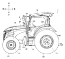
図1はトラクタ1の右面図、図2はトラクタ1の左面図であり、図3はトラクタ1の上面図である。なお、図中には、トラクタ1の前後方向、左右方向及び上下方向を表す。
図1はトラクタ1の右面図、図2はトラクタ1の左面図であり、図3はトラクタ1の上面図である。なお、図中には、トラクタ1の前後方向、左右方向及び上下方向を表す。
トラクタ1は、フレーム11と、エンジン12と、トランスミッション13と、フロントアクスル14と、リヤアクスル15と、キャビン16とを備えている。また、トラクタ1はエンジン12の排気を浄化する排気浄化装置2を備えている。
フレーム11は、トラクタ1の骨格をなす。フレーム11は、トランスミッション13、フロントアクスル14、リヤアクスル15とともにトラクタ1のシャシを構成する。エンジン12及びキャビン16は、防振ゴム等を介してフレーム11に防振支持される。
エンジン12はディーゼルエンジンであり、燃料を燃焼させて得た熱エネルギーを運動エネルギーに変換する。つまり、エンジン12は、燃料を燃やすことによって回転動力を生み出す。なお、エンジン12には、エンジン制御装置が接続されている(図示せず)。エンジン制御装置は、オペレータがアクセルペダルを操作すると、その操作に応じてエンジン12の運転状態を変更する。また、エンジン12には、排気浄化装置2が接続されている。
トランスミッション13は、エンジン12の回転動力をフロントアクスル14やリヤアクスル15に伝達する。トランスミッション13には、連結機構を介してエンジン12の回転動力が入力される。なお、トランスミッション13には、無段変速装置(HST又はHMT、図示せず)が備えられている。無段変速装置は、オペレータがシフトレバーを操作すると、その操作に応じてトランスミッション13の作動状態を変更する。
フロントアクスル14は、エンジン12の回転動力をフロントタイヤ141に伝達する。フロントアクスル14には、トランスミッション13を介してエンジン12の回転動力が入力される。なお、フロントアクスル14には、操舵装置が並設されている(図示せず)。操舵装置は、オペレータがハンドル162を操作すると、その操作に応じてフロントタイヤ141の舵角を変更する。
リヤアクスル15は、エンジン12の回転動力をリヤタイヤ151に伝達する。リヤアクスル15には、トランスミッション13を介してエンジン12の回転動力が入力される。なお、リヤアクスル15には、PTO出力装置(図示せず)が設けられている。PTO出力装置は、オペレータがPTOスイッチ(図示せず)を操作すると、その操作に応じて牽引する作業機に回転動力を伝達する。
キャビン16は、その内側が操縦室になっており、運転座席161、ハンドル162、アクセルペダル(図示せず)、シフトレバー(図示せず)、PTOスイッチなどが配置されている。オペレータは、運転座席161に座った状態でハンドル162、アクセルペダル、シフトレバーなどを操作することでトラクタ1を操縦できる。
<排気浄化装置>
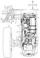
図4はトラクタ1の排気浄化装置2周辺部分の右面図、図5はトラクタ1の排気浄化装置2周辺部分の上面図である。図4及び図5ではボンネットを仮想線で示している。
図4はトラクタ1の排気浄化装置2周辺部分の右面図、図5はトラクタ1の排気浄化装置2周辺部分の上面図である。図4及び図5ではボンネットを仮想線で示している。
排気浄化装置2は、エンジン12の排気中に含まれる粒子状物質(すす、パティキュレート)や窒素酸化物(NOx)等を除去し、浄化された排気を外部へ排出する装置である。排気浄化装置2は、エンジン12の排気中の粒子状物質を除去するディーゼルパティキュレートフィルタ(DPF)としての第1ケース21と、第1ケース21の排気中の窒素酸化物を還元する尿素選択触媒還元(SCR)システムとしての第2ケース22とを備える。第1ケース21には酸化触媒及びスートフィルタが内設される。第2ケース22には尿素選択触媒還元用のSCR触媒及び酸化触媒が内設される。
第1ケース21は前後方向に延びる円筒形状に構成される。第1ケース21はエンジン12の上面にボルト等によって固定される。第2ケース22は上下方向に延びる円筒形状に構成される。第2ケース22はフレーム11に板状のブラケット27を介して固定される。
また、排気浄化装置2は、排気の流れる方向において上流側から、第1ケース21の出口に接続される第1排気管23と、第1排気管23の出口に接続される伸縮管24と、伸縮管24の出口と第2ケース22の入口とを接続する第2排気管25と、第2ケース22の出口に接続される第3排気管26とを備える。
第2排気管25の途中には尿素水噴射ノズル28が配設される。尿素水噴射ノズル28はポンプ及び尿素水タンクに接続され、第2排気管25内に尿素水を噴射する構成となっている。噴射された尿素水は第2排気管25内で排気と混合される。よって、第2排気管25は混合器としての役割がある。第2排気管25のうち尿素水噴射ノズル28から下流側は、排気と尿素水を反応可能な温度に維持する観点から二重管とすることが望ましい。
第3排気管26は、第2ケース22からの排気を外部に排出する排気管である。第3排気管26はブラケット262を介してキャビン16の支柱に固定されている。第3排気管26の周囲はカバー部材261によって覆われている。
このような構成により、エンジン12から排出される排気は排気浄化装置2を経由して外部に放出される。その際、排気浄化装置2によって、排気中の一酸化炭素、炭化水素、粒子状物質、窒素酸化物が低減される。なお、排気浄化装置2は尿素水以外の還元剤を用いる形態であってもよい。
<尿素水タンク及び燃料タンクの配置>
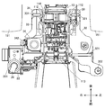
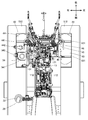
図6は尿素水タンク及び燃料タンク周辺部分の上面図、図7は尿素水タンク及び燃料タンクとフレームと支持台の上面図、図8は尿素水タンク及び燃料タンクとフレームと支持台の下面図である。
図6は尿素水タンク及び燃料タンク周辺部分の上面図、図7は尿素水タンク及び燃料タンクとフレームと支持台の上面図、図8は尿素水タンク及び燃料タンクとフレームと支持台の下面図である。
フレーム11は、トラクタ1の前部における骨格をなす前部フレーム(エンジンフレーム)111(図4参照)と、前部フレーム111の後部に固定される左右の後部フレーム(機体フレーム)112とを有する。前部フレーム111はエンジン12を搭載し、後部フレーム112はトランスミッション13及びキャビン16を搭載する。
またフレーム11は、後部フレーム112に吊り下げ固定され、左右外向きに張り出した前側横桟フレーム113と、トランスミッション13の下面に固定された後側横桟フレーム114とを有する。そして、前側横桟フレーム113及び後側横桟フレーム114の左側端部上に、左側支持台30が架設される。一方、前側横桟フレーム113及び後側横桟フレーム114の右側端部上に、右側支持台31が架設される。
左側支持台30及び右側支持台31は、略矩形枠板状に形成されたプレートである。左側支持台30には、左側燃料タンク32が載置され、バンド321で結束されて固定されている。一方、右側支持台31には、右側燃料タンク33及び尿素水タンク34が並べて載置され、バンド331、341で結束されて固定されている。
左側燃料タンク32、右側燃料タンク33及び尿素水タンク34は、キャビン16の下側であって、フロントタイヤ141及びリヤタイヤ151の間で、且つリヤタイヤ151よりも内側(フレーム11側)に配置される。左側燃料タンク32と、右側燃料タンク33及び尿素水タンク34とは、機体(フレーム11)の左右に振り分けて配置される。
左側燃料タンク32は容量の大きなメイン燃料タンクであり、右側燃料タンク33は左側燃料タンク32よりも容量の小さなサブ燃料タンクである。左側燃料タンク32及び右側燃料タンク33の下部は燃料連通管35で連通され、上部は空気連通管36で連通されている。このように、左側燃料タンク32で容量を確保し、サブの右側燃料タンク33で容量を追加することができる。なお、右側燃料タンク33は省略してもよい。
燃料の給油口322は左側燃料タンク32の前端上部に配置される。また、尿素水の給水口342は尿素水タンク34の上部に配置される。このように、給油口322と給水口342とを機体の左右に振り分けることにより、燃料と尿素水とを入れ間違えることを抑制できる。
なお、給油口322は右側燃料タンク33に配置してもよい。この場合、給油口322と給水口342とを機体の左右同一側に配置することになり、燃料と尿素水とを同じ側で補給することができ利便性がよい。
尿素水タンク34は左側燃料タンク32より小さいので、右側支持台31の空いたスペースにサブ燃料タンクである右側燃料タンク33を配置することで、1つの支持台31に燃料タンク33と尿素水タンク34を配置でき、スペースを有効に活用することができる。また、尿素水タンク34を第2ケース22と同じ側(本実施形態では機体の右側)に配置することにより、尿素水の配管を短くすることができる。
本実施形態においては、尿素水タンク34を前側、右側燃料タンク33を後側に並べて配置しているが、前後逆に配置してもよい。また、本実施形態においては、メイン燃料タンクを機体の左側に、尿素水タンク34及びサブ燃料タンクを右側に配置しているが、左右逆に配置してもよい。
[第2実施形態]
本実施形態ではキャビン仕様のクローラトラクタを例に説明するがロプス仕様のクローラトラクタであってもよい。
本実施形態ではキャビン仕様のクローラトラクタを例に説明するがロプス仕様のクローラトラクタであってもよい。
<クローラトラクタの全体構成>
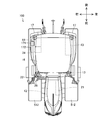
図9はトラクタ100の右面図、図10はトラクタ100の左面図、図11はトラクタ100の上面図である。なお、図中には、トラクタ100の前後方向、左右方向及び上下方向を表す。第1実施形態のトラクタ1と同様の構成については同符号を付し、その詳細な説明を省略する。
図9はトラクタ100の右面図、図10はトラクタ100の左面図、図11はトラクタ100の上面図である。なお、図中には、トラクタ100の前後方向、左右方向及び上下方向を表す。第1実施形態のトラクタ1と同様の構成については同符号を付し、その詳細な説明を省略する。
トラクタ100は、フレーム11と、エンジン12と、トランスミッション13と、フロントアクスル14と、クローラ式走行装置51と、キャビン16と、フェンダー17とを備えている。また、トラクタ100はエンジン12の排気を浄化する排気浄化装置2を備えている。
クローラ式走行装置51は、フロントアクスル14に支持された左右の駆動スプロケット511と、左右の駆動スプロケット511にそれぞれ巻装されたクローラベルト512とを有する。フロントアクスル14は、エンジン12の回転動力を駆動スプロケット511に伝達する。フロントアクスル14には、トランスミッション13を介してエンジン12の回転動力が入力される。なお、フロントアクスル14には、操舵装置が並設されている(図示せず)。操舵装置は、オペレータがハンドル162を操作すると、その操作に応じて左右のクローラベルト512の速度及び回転方向を変更する。フェンダー17は、左右のクローラベルト512を覆うように左右一対設けられている。
<尿素水タンク及び燃料タンクの配置>
図12は尿素水タンク及び燃料タンク周辺部分の上面図、図13は尿素水タンク及び燃料タンクと支持台の上面図、図14は尿素水タンク及び燃料タンクと支持台の下面図、図15は尿素水タンク及び燃料タンクと支持台の右面図である。
図12は尿素水タンク及び燃料タンク周辺部分の上面図、図13は尿素水タンク及び燃料タンクと支持台の上面図、図14は尿素水タンク及び燃料タンクと支持台の下面図、図15は尿素水タンク及び燃料タンクと支持台の右面図である。
トランスミッション13の後部の左右側面にはそれぞれトランスファーケース131が固定されている。両トランスファーケース131の上端部にはそれぞれ略コ字型の支持部材40が固定されている。そして、左側の支持部材40の上面には左側支持台41が固定されている。一方、右側の支持部材40の上面には右側支持台42が固定されている。
左側支持台41及び右側支持台42は、略矩形枠板状に形成されたプレートである。左側支持台41には、左側燃料タンク43が載置され、バンド431で結束されて固定されている。一方、右側支持台42には、右側燃料タンク44及び尿素水タンク34が並べて載置され、バンド441、341で結束されて固定されている。尿素水タンク34は第1実施形態と同様のものを用いることができる。
左側燃料タンク43、右側燃料タンク44及び尿素水タンク34は、フェンダー17の内側に設置される。左側燃料タンク43と、右側燃料タンク44及び尿素水タンク34とは、機体(フレーム11)の左右に振り分けて配置される。
左側燃料タンク43は容量の大きな燃料タンクであり、右側燃料タンク44は左側燃料タンク43よりも容量の小さな燃料タンクである。左側燃料タンク43及び右側燃料タンク44の下部は燃料連通管45で連通され、上部は空気連通管46で連通されている。このように、左側燃料タンク43で容量を確保し、右側燃料タンク44で容量を追加することができる。なお、右側燃料タンク44は省略してもよい。
燃料の給油口442は右側燃料タンク44の上部に配置される。また、尿素水の給水口342は尿素水タンク34の上部に配置される。このように、給油口442と給水口342とを機体の左右同一側に配置することにより、燃料と尿素水とを同じ側で補給することができ利便性がよい。右側のフェンダー17には、給油口442にアクセスするための蓋171と、給水口342にアクセスするための蓋172とが開閉可能に設けられている(図9参照)。
なお、給油口442は左側燃料タンク43に配置してもよい。この場合、給油口442と給水口342とを機体の左右に振り分けることになり、燃料と尿素水とを入れ間違えることを抑制できる。
尿素水タンク34は左側燃料タンク43より小さいので、右側支持台42の空いたスペースに右側燃料タンク44を配置することで、1つの支持台42に燃料タンク44と尿素水タンク34を配置でき、スペースを有効に活用することができる。また、給油口442を給水口342と同一側に配置できる。また、尿素水タンク34を第2ケース22と同じ側(本実施形態では機体の右側)に配置することにより、尿素水の配管を短くすることができる。
本実施形態においては、尿素水タンク34を前側、右側燃料タンク44を後側に並べて配置しているが、前後逆に配置してもよい。また、本実施形態においては、メイン燃料タンクを機体の左側に、尿素水タンク34及びサブ燃料タンクを右側に配置しているが、左右逆に配置してもよい。
以上、第1又は第2実施形態によれば、尿素水タンクの配置を最適化した作業車両を提供することができる。
本発明は、排気浄化装置で用いる還元剤を貯蔵する還元剤タンクを備えた作業車両に利用可能である。
1 トラクタ(作業車両)
2 排気浄化装置
30 左側支持台
31 右側支持台
32 左側燃料タンク
33 右側燃料タンク(サブ燃料タンク)
34 尿素水タンク(還元剤タンク)
41 左側支持台
42 右側支持台
43 左側燃料タンク
44 右側燃料タンク(サブ燃料タンク)
100 トラクタ(作業車両)
322 給油口
342 給水口
442 給油口
2 排気浄化装置
30 左側支持台
31 右側支持台
32 左側燃料タンク
33 右側燃料タンク(サブ燃料タンク)
34 尿素水タンク(還元剤タンク)
41 左側支持台
42 右側支持台
43 左側燃料タンク
44 右側燃料タンク(サブ燃料タンク)
100 トラクタ(作業車両)
322 給油口
342 給水口
442 給油口
Claims (4)
- 燃料タンクと、排気浄化装置で用いる還元剤を貯蔵する還元剤タンクとを備えた作業車両において、
前記燃料タンクは給油口を有し、
前記燃料タンクと前記還元剤タンクとを機体の左右に振り分けて配置したことを特徴とする作業車両。 - 前記還元剤タンクに並設されるサブ燃料タンクと、
前記還元剤タンク及び前記サブ燃料タンクを支持する支持台とを備えたことを特徴とする請求項1に記載の作業車両。 - 燃料タンクと排気浄化装置で用いる還元剤を貯蔵する還元剤タンクとを備えた作業車両において、
機体の左右一方側に、前記燃料タンク及び前記還元剤タンクを並べて支持する支持台を設けたことを特徴とする作業車両。 - 前記機体の左右他方側に、メイン燃料タンクを備えたことを特徴とする請求項3に記載の作業車両。
Priority Applications (3)
| Application Number | Priority Date | Filing Date | Title |
|---|---|---|---|
| KR1020197035265A KR102090054B1 (ko) | 2015-10-23 | 2016-10-21 | 작업 차량 |
| KR1020187014304A KR102052002B1 (ko) | 2015-10-23 | 2016-10-21 | 작업 차량 |
| KR1020207007134A KR20200029630A (ko) | 2015-10-23 | 2016-10-21 | 작업 차량 |
Applications Claiming Priority (2)
| Application Number | Priority Date | Filing Date | Title |
|---|---|---|---|
| JP2015-209406 | 2015-10-23 | ||
| JP2015209406A JP2017081259A (ja) | 2015-10-23 | 2015-10-23 | 作業車両 |
Publications (1)
| Publication Number | Publication Date |
|---|---|
| WO2017069239A1 true WO2017069239A1 (ja) | 2017-04-27 |
Family
ID=58557221
Family Applications (1)
| Application Number | Title | Priority Date | Filing Date |
|---|---|---|---|
| PCT/JP2016/081268 Ceased WO2017069239A1 (ja) | 2015-10-23 | 2016-10-21 | 作業車両 |
Country Status (3)
| Country | Link |
|---|---|
| JP (3) | JP2017081259A (ja) |
| KR (3) | KR102052002B1 (ja) |
| WO (1) | WO2017069239A1 (ja) |
Cited By (1)
| Publication number | Priority date | Publication date | Assignee | Title |
|---|---|---|---|---|
| CN110549842A (zh) * | 2018-05-31 | 2019-12-10 | 井关农机株式会社 | 作业车辆 |
Families Citing this family (3)
| Publication number | Priority date | Publication date | Assignee | Title |
|---|---|---|---|---|
| US11660955B2 (en) | 2019-03-18 | 2023-05-30 | Kubota Corporation | Fuel tank of work vehicle and work vehicle |
| KR20240142765A (ko) * | 2023-03-22 | 2024-10-02 | 엘에스엠트론 주식회사 | 농용 트랙터 |
| JP2025063746A (ja) * | 2023-10-04 | 2025-04-16 | 井関農機株式会社 | 作業車両 |
Citations (7)
| Publication number | Priority date | Publication date | Assignee | Title |
|---|---|---|---|---|
| JPS58209661A (ja) * | 1982-06-01 | 1983-12-06 | Nissan Motor Co Ltd | フオ−クリフトのフレ−ム構造 |
| JPS5965825U (ja) * | 1982-10-27 | 1984-05-02 | 日野自動車株式会社 | サブ燃料タンク付車輛の燃料タンクシステム |
| JP2010236208A (ja) * | 2009-03-30 | 2010-10-21 | Sumitomo (Shi) Construction Machinery Co Ltd | 建設機械 |
| JP2014121921A (ja) * | 2012-12-20 | 2014-07-03 | Yanmar Co Ltd | 作業車両 |
| JP2014151764A (ja) * | 2013-02-08 | 2014-08-25 | Yanmar Co Ltd | 作業車両のエンジン装置 |
| JP2015045235A (ja) * | 2013-08-27 | 2015-03-12 | 日立建機株式会社 | 作業機械の排気ガス浄化装置 |
| JP2016203753A (ja) * | 2015-04-20 | 2016-12-08 | 井関農機株式会社 | 作業車両 |
Family Cites Families (8)
| Publication number | Priority date | Publication date | Assignee | Title |
|---|---|---|---|---|
| JP2002307962A (ja) * | 2001-04-09 | 2002-10-23 | Yanmar Agricult Equip Co Ltd | クローラトラクタ |
| DE10305057A1 (de) * | 2003-02-07 | 2004-08-19 | Daimlerchrysler Ag | Abgasnachbehandlungssystem und Nutzfahrzeug mit Abgasnachbehandlungssystem |
| JP5562777B2 (ja) * | 2010-09-16 | 2014-07-30 | 日立建機株式会社 | 建設機械 |
| WO2014175168A1 (ja) * | 2013-04-26 | 2014-10-30 | ヤンマー株式会社 | 作業車両 |
| JP6177118B2 (ja) * | 2013-12-11 | 2017-08-09 | ヤンマー株式会社 | トラクタ |
| JP2015117597A (ja) * | 2013-12-17 | 2015-06-25 | ヤンマー株式会社 | 作業車両 |
| JP2015189396A (ja) * | 2014-03-28 | 2015-11-02 | ヤンマー株式会社 | 作業車両 |
| JP2019209661A (ja) * | 2018-06-08 | 2019-12-12 | 日本製鉄株式会社 | フラットパネル構造 |
-
2015
- 2015-10-23 JP JP2015209406A patent/JP2017081259A/ja active Pending
-
2016
- 2016-10-21 WO PCT/JP2016/081268 patent/WO2017069239A1/ja not_active Ceased
- 2016-10-21 KR KR1020187014304A patent/KR102052002B1/ko active Active
- 2016-10-21 KR KR1020207007134A patent/KR20200029630A/ko not_active Ceased
- 2016-10-21 KR KR1020197035265A patent/KR102090054B1/ko active Active
-
2020
- 2020-08-06 JP JP2020133517A patent/JP6985470B2/ja active Active
-
2021
- 2021-11-25 JP JP2021190756A patent/JP7545948B2/ja active Active
Patent Citations (7)
| Publication number | Priority date | Publication date | Assignee | Title |
|---|---|---|---|---|
| JPS58209661A (ja) * | 1982-06-01 | 1983-12-06 | Nissan Motor Co Ltd | フオ−クリフトのフレ−ム構造 |
| JPS5965825U (ja) * | 1982-10-27 | 1984-05-02 | 日野自動車株式会社 | サブ燃料タンク付車輛の燃料タンクシステム |
| JP2010236208A (ja) * | 2009-03-30 | 2010-10-21 | Sumitomo (Shi) Construction Machinery Co Ltd | 建設機械 |
| JP2014121921A (ja) * | 2012-12-20 | 2014-07-03 | Yanmar Co Ltd | 作業車両 |
| JP2014151764A (ja) * | 2013-02-08 | 2014-08-25 | Yanmar Co Ltd | 作業車両のエンジン装置 |
| JP2015045235A (ja) * | 2013-08-27 | 2015-03-12 | 日立建機株式会社 | 作業機械の排気ガス浄化装置 |
| JP2016203753A (ja) * | 2015-04-20 | 2016-12-08 | 井関農機株式会社 | 作業車両 |
Cited By (2)
| Publication number | Priority date | Publication date | Assignee | Title |
|---|---|---|---|---|
| CN110549842A (zh) * | 2018-05-31 | 2019-12-10 | 井关农机株式会社 | 作业车辆 |
| CN110549842B (zh) * | 2018-05-31 | 2025-04-01 | 井关农机株式会社 | 作业车辆 |
Also Published As
| Publication number | Publication date |
|---|---|
| JP7545948B2 (ja) | 2024-09-05 |
| KR20180072775A (ko) | 2018-06-29 |
| JP6985470B2 (ja) | 2021-12-22 |
| JP2022022274A (ja) | 2022-02-03 |
| KR20200029630A (ko) | 2020-03-18 |
| KR102052002B1 (ko) | 2019-12-04 |
| JP2020193621A (ja) | 2020-12-03 |
| KR20190135560A (ko) | 2019-12-06 |
| JP2017081259A (ja) | 2017-05-18 |
| KR102090054B1 (ko) | 2020-03-17 |
Similar Documents
| Publication | Publication Date | Title |
|---|---|---|
| JP7545948B2 (ja) | トラクタ | |
| JP5688167B2 (ja) | 建設機械 | |
| KR102664511B1 (ko) | 작업 차량 | |
| CN105209281B (zh) | 工程机械 | |
| KR102089930B1 (ko) | 작업 차량 | |
| JP2016203753A5 (ja) | ||
| CN104040077A (zh) | 工程车辆 | |
| JP6000931B2 (ja) | 作業車両 | |
| JP6492921B2 (ja) | トラクタ | |
| JP2016203752A5 (ja) | ||
| JP6442745B2 (ja) | トラクタ | |
| JP7243792B2 (ja) | トラクタ | |
| JP7348937B2 (ja) | トラクタ | |
| JP6624276B2 (ja) | トラクタ | |
| CN106103172B (zh) | 作业车辆 | |
| JP6721031B2 (ja) | トラクタ | |
| JP2020152374A (ja) | トラクタ | |
| CN106103172A (zh) | 作业车辆 |
Legal Events
| Date | Code | Title | Description |
|---|---|---|---|
| 121 | Ep: the epo has been informed by wipo that ep was designated in this application |
Ref document number: 16857552 Country of ref document: EP Kind code of ref document: A1 |
|
| DPE1 | Request for preliminary examination filed after expiration of 19th month from priority date (pct application filed from 20040101) | ||
| NENP | Non-entry into the national phase |
Ref country code: DE |
|
| ENP | Entry into the national phase |
Ref document number: 20187014304 Country of ref document: KR Kind code of ref document: A |
|
| 122 | Ep: pct application non-entry in european phase |
Ref document number: 16857552 Country of ref document: EP Kind code of ref document: A1 |