WO2017069008A1 - 車両用照明保持構造 - Google Patents
車両用照明保持構造 Download PDFInfo
- Publication number
- WO2017069008A1 WO2017069008A1 PCT/JP2016/080011 JP2016080011W WO2017069008A1 WO 2017069008 A1 WO2017069008 A1 WO 2017069008A1 JP 2016080011 W JP2016080011 W JP 2016080011W WO 2017069008 A1 WO2017069008 A1 WO 2017069008A1
- Authority
- WO
- WIPO (PCT)
- Prior art keywords
- light guide
- light
- interior trim
- holding structure
- illumination
- Prior art date
Links
Images


Classifications
-
- B—PERFORMING OPERATIONS; TRANSPORTING
- B60—VEHICLES IN GENERAL
- B60Q—ARRANGEMENT OF SIGNALLING OR LIGHTING DEVICES, THE MOUNTING OR SUPPORTING THEREOF OR CIRCUITS THEREFOR, FOR VEHICLES IN GENERAL
- B60Q3/00—Arrangement of lighting devices for vehicle interiors; Lighting devices specially adapted for vehicle interiors
- B60Q3/20—Arrangement of lighting devices for vehicle interiors; Lighting devices specially adapted for vehicle interiors for lighting specific fittings of passenger or driving compartments; mounted on specific fittings of passenger or driving compartments
- B60Q3/217—Doors, e.g. door sills; Steps
-
- B—PERFORMING OPERATIONS; TRANSPORTING
- B60—VEHICLES IN GENERAL
- B60Q—ARRANGEMENT OF SIGNALLING OR LIGHTING DEVICES, THE MOUNTING OR SUPPORTING THEREOF OR CIRCUITS THEREFOR, FOR VEHICLES IN GENERAL
- B60Q3/00—Arrangement of lighting devices for vehicle interiors; Lighting devices specially adapted for vehicle interiors
- B60Q3/20—Arrangement of lighting devices for vehicle interiors; Lighting devices specially adapted for vehicle interiors for lighting specific fittings of passenger or driving compartments; mounted on specific fittings of passenger or driving compartments
- B60Q3/267—Door handles; Hand grips
-
- B—PERFORMING OPERATIONS; TRANSPORTING
- B60—VEHICLES IN GENERAL
- B60Q—ARRANGEMENT OF SIGNALLING OR LIGHTING DEVICES, THE MOUNTING OR SUPPORTING THEREOF OR CIRCUITS THEREFOR, FOR VEHICLES IN GENERAL
- B60Q3/00—Arrangement of lighting devices for vehicle interiors; Lighting devices specially adapted for vehicle interiors
- B60Q3/60—Arrangement of lighting devices for vehicle interiors; Lighting devices specially adapted for vehicle interiors characterised by optical aspects
- B60Q3/62—Arrangement of lighting devices for vehicle interiors; Lighting devices specially adapted for vehicle interiors characterised by optical aspects using light guides
- B60Q3/64—Arrangement of lighting devices for vehicle interiors; Lighting devices specially adapted for vehicle interiors characterised by optical aspects using light guides for a single lighting device
Definitions
- the present invention relates to an illumination holding structure for a vehicle, particularly an automobile.
- the interior of the car (and sometimes the exterior) is provided with an illumination structure for use by passengers.
- the lighting structure light emitted from the lighting device may enter directly into the eyes of the occupant or may enter the eyes of the occupant indirectly by reflecting the irradiated portion of the automobile interior member.
- a lighting structure in an automobile room for example, a door trim
- it is generally performed to provide a lighting device including a long light guide.
- Patent Document 1 Japanese Patent No. 5608538.
- Patent Document 2 Japanese Patent No. 4529900.
- the diffusion effect is enhanced and light is emitted evenly.
- the light guide is sometimes covered with the housing to prevent the light guide from being damaged, but there is a variation in light emission at the contact portion between the housing and the light guide.
- the rib portion supporting the light guide supports the light guide over the entire width of the light guide (for example, FIG. 4 of Patent Document 1). The presence of the contact surface between the light body and the support causes abnormal light emission of the light guide, and there is a problem that uniform light emission cannot be performed.
- An object of the present invention is to improve the uniformity of vehicle interior illumination by improving the problem of abnormal light emission caused by the contact between the light guide of the lighting device and the holding member in the vehicle lighting holding structure.
- the vehicle illumination holding structure of the present invention is A rod-shaped light guide attached to the interior trim, a holding member that holds the light guide, and a transmission portion that is provided in the interior trim and has a gap between the light exit surface of the light guide, The exit surface along the longitudinal direction of the light guide is opposed to the transmission part of the interior trim,
- the holding member is extended from the interior trim,
- the front end portion of the holding member has a locking body that is locked to one side surface along the longitudinal direction of the light guide,
- the interior trim is A support that reaches the exit surface of the light guide beyond the other side opposite to the one side in the light guide; It is the illumination holding structure for vehicles which has the level
- abnormal light emission can be suppressed by preventing contact between the transmission part and the light exit surface of the light guide.
- the support portion extends to the vicinity of a prism position formed on a reflection surface facing the emission surface of the light guide.
- the vicinity means a range of 0.2 D or less from the side edge on the other side surface of the prism with respect to the dimension D of the prism in the light guide width direction.
- the prism is further formed closer to one side surface on the reflection surface of the light guide.
- the illumination light that is transmitted through the reflection surface on the support portion and guided by multiple reflection is mainly from the portion of the light exit surface of the light guide that is located outside the support portion. Since it emits, the generation of abnormal light can be more efficiently suppressed.
- the engagement body and the support portion may be arranged alternately along the longitudinal direction of the light guide. According to the illumination holding structure for a vehicle having such a configuration, the area of the support portion that comes into contact with the light guide can be reduced, and the light guide can be stably supported by the interior trim while suppressing generation of abnormal light. .
- the fixing member since the fixing member does not come into contact with the light irradiation range of the light guide, abnormal light emission due to contact can be eliminated. Is possible.
- the vehicle lighting structure refers to a structure including an automobile member (automobile part) illuminated by light emitted from a lighting device in an interior structure or exterior structure of a vehicle (for example, an automobile).
- the vehicle illumination holding structure refers to a structure including an illumination device (in particular, an illumination body such as a light guide) and a member that holds the illumination apparatus in the above illumination structure.
- the automobile lighting holding structure and the lighting structure including the same according to the present invention can be a part of the structure of the door trim.
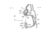
- FIG. 1 is a perspective view of a door trim having an illumination holding structure according to the present invention.
- the lighting device 5 is held outside the interior of the door trim decorating member 3 which is a part of the interior trim, and light emitted from the lighting device irradiates the interior of the vehicle.
- the light guide 51 used in the lighting device has a long bar shape, and is arranged so that the longitudinal direction is along the front-rear direction (door closed state) of the door trim.
- the gripping member of the inside handle unit 4 as the irradiated portion is illuminated by the light emitted from the illumination holding structure.
- the inside handle unit 4 includes a gripping part 41, a bezel 42, and a cover body 43.
- the shape of the gripping portion 41 is determined in consideration of design and operability.
- the side surface 41b facing the vehicle interior from the top surface 41a facing the decorating member 3 and A curved surface is formed with a predetermined curvature R continuously from the side surface 41 c facing the cover body 43.
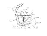
- FIG. 3 shows a schematic cross-sectional view in which the illumination holding structure portion in FIG. 2 is enlarged.
- a locking portion 32 (holding member) having a locking claw (locking body) 32 a is formed on the vehicle exterior side of the vehicle interior member of the decorating member 3.
- a plurality of the locking portions 32 are formed along the longitudinal direction of the light guide, and the light guide 51 is sandwiched and fixed between the support portion 34 and the locking portion 32 formed on the decorative member.
- the decorating member 3 serves as a holder for the light guide 51.
- a thin transmission part 31 is provided on the bottom wall 30 of the decorative member 3, and light emitted from the light guide 51 passes through the transmission part 31 and is irradiated to the irradiated site.
- the polycarbonate is used and the irradiation of the light from the permeation
- the design property is improved by giving the design surface 33 facing the vehicle interior of the decorating member 3 except the transmission part 31 with an arbitrary color.
- a skin may be laminated.
- the transmissive portion 31 is formed such that the upper surface thereof is separated from the emission surface 54, which is the lower surface of the light guide 51, at a predetermined interval. Therefore, a step portion 35 is formed between the support portion 34 and the transmission portion 31.
- the size of the gap S is preferably about 0.1 to 10 mm, more preferably 0.5 to 5 mm.
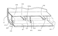
- FIG. 4 shows a perspective view of a state in which a part of the decorative member 3 holding the light guide 51 is cut out.
- a flange 36 that holds down a part of the reflection surface 55 of the light guide 51 (near the side end located on the support), and this flange A locking portion 32 extends from 36.
- the hook part 36 may be omitted and the locking part 32 may protrude directly from the side wall of the decorative member 3.
- a locking claw 32 a at the tip of the locking portion 32 in FIG. 3 is locked to one side surface 51 a along the longitudinal direction of the light guide 51.
- plate-like support portions 34 that are arranged at appropriate intervals and project upward are formed.
- the light guide 51 is separated from the transmission part 31 by the light guide 51 being supported on the support part 34.
- the locking portions 32 and the support portions 34 are preferably arranged alternately along the longitudinal direction of the light guide 51.
- the portions that contact the support portion 34 and the locking claw 32a at the tip of the locking portion 32 are arranged in a zigzag shape when viewed from above when the portions are connected by line segments.
- locking part 32 are arrange
- the support portion 34 is provided as a part of a partition wall 37 that serves both as position regulation of the light guide 51 and reinforcement of the flange portion 36. However, the partition wall 37 may be omitted, and the support portion 34 may protrude directly from the side wall of the decorative member 3.
- the portion where the support portion 34 is in contact with the light guide 51 does not overlap with the light emission region (main emission region) on the emission surface 54 of the light guide 51. For this reason, it is preferable not to be directly under the optical pattern (prism) 53 formed on the reflection surface 56 of the light guide 51.
- the support portion 34 is preferably extended to the vicinity of the optical pattern (prism) 53, and the dimension D of the prism in the width direction of the light guide 51 is set. On the other hand, it may be extended from the side end of the prism (side end near the support portion) to a position of 0.2D or less.
- the support portion 34 is preferably a thin plate having a small dimension along the longitudinal direction of the light guide 51 so as not to block the light emitted from the light guide 51 as much as possible. Even when the collar part 36 holds a part of the reflection surface of the light guide 51, the part where the collar part 36 is in contact with the light guide 51 does not overlap the light reflection region (main reflection region) of the light guide 51. It is preferable. For this reason, it is preferable that the reflective surface 56 does not overlap the region where the optical pattern 53 is formed.
- FIG. 5 is a perspective view of the illumination device 5 used in the present invention.
- the illumination device 5 of the present embodiment includes a light source 52 at one end of a long rod-shaped light guide 51.
- the light source includes a light source body (not shown), a case body, and a wiring harness, and is assembled to the door trim body by an engaging portion formed on the case body.
- the harness is connected to a power source for electronic components (not shown) provided in the vehicle compartment via a connector.
- the type of the light source body is not particularly limited, and an incandescent bulb, a halogen lamp, or the like can be used.
- a light emitting diode LED
- LED does not ask
- the light source is provided only at one end of the light guide. However, light emission unevenness may be prevented by providing the light source at both ends of the light guide. The design effect may be enhanced by using a combination of a plurality of light source bodies having different emission colors.
- the light guide in the present embodiment has a long rod shape, but is not limited to a rod shape, and may be a plate shape, a cylindrical shape, or the like.
- the light guide is not limited to a straight line but may be a curved line, or may be a combination of a straight line and a curved line.
- the cross-sectional shape of the light guide is not particularly limited, and may be circular or trapezoidal, but in the present embodiment, it is rectangular (for example, it may be 5 mm wide ⁇ 2 mm to 5 mm high).
- the material of the light guide is not particularly limited, but may be an acrylic resin, and PMMA is used in this embodiment.
- a layer may be formed on the surface of the light guide body by painting or sticking a film.
- the cross-sectional shape of the optical pattern 53 is not particularly limited, and includes a semicircular shape, a triangular shape, an elliptical shape, a quadrangular shape, and the like.
- d may be 0.1 mm.
- FIG. 6 shows a partially enlarged view of the light guide 51 used in the present invention
- FIG. 7 shows a cross section taken along line BB in FIG.
- the light from the light source 52 in FIG. 5 enters from the light incident surface 56 formed on one end side of the light guide bar 51 toward the other end side along the longitudinal direction, and is formed on the reflecting surface 55 in FIG. Due to the optical pattern, the light is reflected toward the emission surface 54 facing the reflection surface 55, passes through the emission surface 54, and is irradiated to the gripping portion 41 that is the irradiation target through the transmission portion 31 of the decorating member 3 in FIG. 2.
- the optimum conditions are selected depending on the size and shape of the light guide 51, the material and shape of the gripper 41, the positional relationship between the lightguide 51 and the gripper 41, and the like. It is preferable.
- the optical pattern 53 is preferably formed obliquely with respect to a plane orthogonal to the longitudinal direction (X-axis direction) of the light guide in FIG. 5, that is, the YZ plane.
- a plane orthogonal to the longitudinal direction (X-axis direction) of the light guide in FIG. 5, that is, the YZ plane As a result, when light is irradiated onto the curved surface of the object to be illuminated, adjacent optical patterns are overlapped with each other, and an image reflected on the curved surface becomes a single line.
- the range of the inclination angle ⁇ (inclination angle with respect to the YZ plane) of the optical pattern 53 shown in FIG. 6 is 10 ° to 80 °, the particularly preferable range is 20 ° to 60 °, and more preferably 25 to 40 °. .
- the positive direction of the inclination angle ⁇ is clockwise in the XY plane when viewed from the reflecting surface 55 side, but counterclockwise may be the positive direction. That is, the inclination direction of the optical pattern 53 in FIG. 6 may be reversed between the positive direction and the negative direction of the X axis.
- one end b1 on the longitudinal direction side of one optical pattern a1 and the other end b2 of the adjacent optical pattern a2 are included in the light guide 51.
- the coordinates in the extending direction (X-axis direction) may be substantially the same. That is, the line C passing through the X-axis positive direction end b1 of one optical pattern a1 and parallel to the YZ plane, and the X-axis negative direction side of the optical pattern a2 adjacent in the X-axis positive direction.
- a line C ′ that passes through the end b2 and is parallel to the YZ plane overlaps to coincide in the XY plane.
- Adjacent optical patterns may overlap each other with no gap by slightly overlapping the longitudinal coordinates of the light guide 51. That is, a line C that passes through the X-axis positive direction side end b1 of the optical pattern a1 and is parallel to the YZ plane may intersect with the optical pattern a2 that is adjacent in the X-axis positive direction. A line C ′ passing through the X-axis negative direction side end b2 of a2 and parallel to the YZ plane may intersect the optical pattern a1. Thereby, when light is irradiated onto the curved surface, the image reflected on the curved surface is more likely to become a line shape.
- At least a part of one optical pattern a1 and at least a part of the other optical pattern a2 are the same orthogonal to the longitudinal direction of the light guide. Will be on the surface.
- the pitch p between adjacent optical patterns may be changed, and at least of the dimensions (length x, depth d, width w, etc.) of the optical pattern 53 One element) may be changed.
- the depth d of the optical pattern may be changed in the range of about 0.1 to 0.5 mm.
- the light guide 51 may have a tapered shape in which the cross-sectional area of the transverse section (YZ section) decreases as the distance from the light source 52 increases. As a result, the number of times the light is reflected in the light guide 51 is increased, and the amount of emitted light can be increased without changing the shape and number of the optical patterns 53 formed on the light guide 51. Can be prevented from becoming dark.
- an optical pattern 53 is formed in a region that is biased toward one side surface 51a of the light guide.
- the vicinity of the other side surface 51b without the optical pattern 53 of the reflecting surface on the emission surface 54 is supported by the support portion 34, and the influence of contact with the support portion 34 on light emission can be suppressed.
- the width of the main light emitting region (main reflection region) excluding the width W2 of the portion supported by the support portion 34 from the lateral width W of the light guide is W1, and the optical pattern 53 is Y in the XY plane.
- the optical pattern (prism) 53 is provided at the center of the width W1, but the optical pattern 53 may be positioned closer to the support portion 34 in the width W1.
- the position in the width direction of the end (the side end b2 of the optical pattern a2) and the position of the tip of the support portion 34 may be the same.
- variety of the part shall be W2 or less.
- the optical pattern may be provided at the center of the light guide 51 in the width direction.
- the light guide may have a tapered shape in which the cross-sectional area of the cross section decreases as the distance from the light source increases. This increases the number of reflections of light in the light guide, increases the amount of emitted light without changing the shape and number of optical patterns formed on the light guide, and makes the tip of the light guide dark. Can be prevented.
- the optical pattern is formed at the same time as the injection molding by providing a convex portion at a position corresponding to the optical pattern in the injection mold in order to form the light guide.
- it may be formed by cutting or laser processing after injection molding.
- the object which provides the illumination holding structure for motor vehicles may be not only a door trim but an instrument panel, a ceiling, a center console, etc.
- the target portion to be irradiated with light in the door trim may be an inside handle, a switch panel, an assist grip, or the like. Therefore, the interior trim is not limited to the decorative member of the door trim. Moreover, you may apply not only to a vehicle interior but to components outside a vehicle interior. The present invention is not limited to the above-described embodiment, and modifications and changes can be made without departing from the scope of the claims.
- the abnormal light emission due to the contact between the light guide and the interior trim member holding the light guide is suppressed, and the illuminated portion of the automobile member is irradiated with illumination light in a uniform light emission state. It is possible to improve the operability and design of the automobile.
Landscapes
- Engineering & Computer Science (AREA)
- Mechanical Engineering (AREA)
- Arrangements Of Lighting Devices For Vehicle Interiors, Mounting And Supporting Thereof, Circuits Therefore (AREA)
- Planar Illumination Modules (AREA)
Abstract
内装トリムに装着される棒状の導光体(51)と、前記導光体を保持する保持部材(32)と、内装トリムに設けられて、導光体の出射面との間に隙間を有する透過部(31)とを備え、導光体の長手方向に沿った出射面(54)が内装トリムの透過部(31)に対向しており、保持部材(32)は内装トリムより延出されており、保持部材(32)の先端部分には導光体の長手方向に沿った一側面に係止される係止体(32a)を有し、内装トリムがさらに、導光体における前記一側面と反対側の他側面を越えて導光体の出射面にまで達する支持部(34)と、前記支持部と前記透過部とを接続する段差部(35)とを有する車両用照明保持構造。
Description
本願は、日本国で2015年10月21日に出願した特願2015-207466の優先権を主張するものであり、その全体を参照により本出願の一部をなすものとして引用する。
本発明は、車両、特に自動車用の照明保持構造に関する。
自動車の内装(時には外装)には搭乗者の利用に供するための照明構造が設けられている。照明構造において、照明装置から照射された光は、乗員の目に直接入る場合と、自動車内装部材の被照射部位を反射して、乗員の目に間接的に入る場合とがある。間接的にすることで、眩しさの低減効果や、被照射部位に模様を演出し意匠性を高める効果、被照射部位を際立たせることで位置がわかりやすくし操作性を高める効果、等が得られる。
従来から、自動車室内(例えばドアトリム)の照明構造において、長尺の導光体を備えた照明装置を設けることは一般的に行われている。
例えば、本出願人はドアトリムのオーナメント部分に、長手の照射部を備えた導光体を備えた照明装置を設けている(特許文献1:特許第5608538号)。
従来から用いられている長尺の導光体では、表面に長手方向の軸と直交する方向に延びる溝状のパターンを形成しており(例えば特許文献2:特許第4529900号)、これによって光の拡散効果を高め、ムラなく光を照射している。
しかし、従来の照明構造では、導光体の傷付き防止にハウジングで導光体を覆うことがあるが、ハウジングと導光体の接触部分において発光にばらつきがあった。また、導光体を固定保持する構造において、導光体を支えるリブ部が導光体のすべての幅に渡って導光体を支持していた為(例えば特許文献1の図4)、導光体と支持体との接触面の存在が、導光体の異常発光の原因となり、均一発光が出来ていないことが問題となっている。
本発明は、車両用照明保持構造において、照明装置の導光体と保持部材の接触に起因する異常発光の問題を改善することで車室内照射の均一性を高めることを目的とする。
本発明の車両用照明保持構造は、
内装トリムに装着される棒状の導光体と、前記導光体を保持する保持部材と、内装トリムに設けられて、導光体の出射面との間に隙間を有する透過部とを備え、
導光体の長手方向に沿った出射面が内装トリムの透過部に対向しており、
保持部材は内装トリムより延出されており、
保持部材の先端部分には導光体の長手方向に沿った一側面に係止される係止体を有し、
内装トリムがさらに、
導光体における前記一側面と反対側の他側面を越えて導光体の出射面にまで達する支持部と、
前記支持部と前記透過部とを接続する段差部とを有する
車両用照明保持構造である。
内装トリムに装着される棒状の導光体と、前記導光体を保持する保持部材と、内装トリムに設けられて、導光体の出射面との間に隙間を有する透過部とを備え、
導光体の長手方向に沿った出射面が内装トリムの透過部に対向しており、
保持部材は内装トリムより延出されており、
保持部材の先端部分には導光体の長手方向に沿った一側面に係止される係止体を有し、
内装トリムがさらに、
導光体における前記一側面と反対側の他側面を越えて導光体の出射面にまで達する支持部と、
前記支持部と前記透過部とを接続する段差部とを有する
車両用照明保持構造である。
上記車両用照明保持構造によれば、透過部と導光体の光出射面との接触を防ぐことにより、異常発光を抑制することができる。
本発明の車両用照明保持構造において、前記支持部は導光体における出射面と対向する反射面に形成されたプリズム位置の近傍まで延出されていることが好ましい。ここで、近傍とは、導光体幅方向のプリズムの寸法Dに対し、プリズムの前記他側面側の側端から0.2D以下の範囲をいう。
上記本発明の車両用照明保持構造において、さらに前記プリズムが導光体の反射面における一側面寄りに形成されていることが好ましい。
前記の構成によれば、支持部上の反射面では光が透過し、多重反射により導光される照明光は、導光体の光出射面の、支持部の外側に位置する部分から主に出射するため、異常光の発生をさらに効率的に抑制することができる。
上記本発明の車両用照明保持構造は、前記係止体と前記支持部との配置が導光体の長手方向に沿って交互に並んでいるものであってもよい。このような構成の車両用照明保持構造によれば、導光体と接触する支持部の面積を低減して、異常光の発生を抑制しながら、導光体を内装トリムに安定して支持できる。
本発明の車両用照明保持構造の構成によれば、導光体の光照射範囲に固定部材が接触することが無いことにより、接触による異常発光を無くすことができるため、導光体の均一発光が可能となる。
なお、請求の範囲および/または明細書に開示された少なくとも2つの構成要素のどのような組み合わせも、本発明に含まれる。特に、請求の範囲に記載された請求項の2つ以上のどのような組み合わせも本発明に含まれる。
この発明は、添付の図面を参考にした以下の好適な実施形態の説明からより明瞭に理解されるであろう。しかしながら、実施形態および図面は単なる図示および説明のためのものであり、この発明の範囲を定めるために利用されるべきでない。この発明の範囲は添付のクレームによって定まる。
本発明に係る照明装置を備えたドアトリムの斜視図である。
図1のA-A線断面である。
本発明に使用される照明保持構造を模式的に示す断面図である。
本発明の照明保持構造を構成する内装トリムの一部分の形態を示す斜視図である。
本発明に使用される照明装置を模式的に示す斜視図である。
本発明に使用される照明装置の部分的な拡大図である。
導光体に形成される光学パターン(プリズム)の模式断面図である。
以下、本発明の実施形態について、図面を参照して説明する。
(ドアトリム)
本発明の記載において、車両用照明構造とは、車両(例えば自動車)の内装構造もしくは外装構造において、照明装置から照射される光によって照明される自動車部材(自動車部品)とを含む構造をいうものとする。また、車両用照明保持構造とは、上記の照明構造において、照明装置(特に導光体等の照明体)と、これを保持する部材を含む構造をいうものとする。
本発明の自動車用照明保持構造およびこれを含む照明構造は、ドアトリムの構成の一部とすることができ。図1は、本発明に係る照明保持構造を備えたドアトリムの斜視図である。
図2に、図1におけるA-A線断面図を示す。図で右矢印は車室外側、左矢印は車室内側を、符号7はドア外板を示す。照明装置5は内装トリムの一部である、ドアトリムの加飾部材3の車室外側に保持され、照明装置から放出された光が、車両内装を照射する。照明装置に用いられる導光体51は、本実施形態では長尺な棒状であり、長手方向がドアトリムの前後方向(ドア閉状態)に沿うように配置されている。本実施形態の照明構造6においては、上記の照明保持構造から照射された光により、被照射部位としてのインサイドハンドルユニット4の把持部材が照明される。
インサイドハンドルユニット4は把持部41とベゼル42、カバー体43とで構成されている。把持部41は、意匠性や操作性を考慮して形状が決定されるが、本実施形態の把持部41では、加飾部材3に対向する頂面41aから、車室内に対向する側面41bおよびカバー体43に対向する側面41cに連続して所定の曲率Rで曲面が形成されている。
(照明保持構造)
図3に、図2における照明保持構造部分を拡大した模式的断面図を示す。
加飾部材3の車室部材の車室外側には係止爪(係止体)32aを有する係止部32(保持部材)が形成されている。この係止部32は、導光体の長手方向に沿って複数形成されており、加飾部材に形成された支持部34と係止部32とで導光体51を挟みこんで固定することで、加飾部材3は導光体51の保持体としての役割を果たす。本実施形態において加飾部材3の底壁30には薄肉の透過部31が設けられており、導光体51から放出された光が透過部31を通り抜けて被照射部位に照射される。加飾部材3の材質に特に限定はないが、本実施形態ではポリカーボネートを用いており、薄いポリカーボネートで形成された透過部31からの光の照射を可能としている。また、透過部31を除く加飾部材3の車室内に面する意匠面33には任意の色で塗装を施すことで意匠性を高めている。塗装に代えて、表皮を積層してもよい。
図3に示すように、本発明では、透過部31は、その上面が、導光体51の下面である出射面54と所定の間隔で離間するように形成されている。そのため、支持部34と透過部31の間には、段差部35が形成される。本発明では、上記の構成により、導光体51と透過部31との間に隙間Sが設けられているので、接触面の存在に起因する異常光の発生を抑止できる。ここで、隙間Sの大きさは、0.1~10mm程度であることが好ましく、より好ましくは0.5~5mmである。
本発明に係る内装トリム形状の実施形態として、図4に、導光体51を保持する加飾部材3の一部を切り取った状態の斜視図を示す。図4に示すように、加飾部材3の側壁に沿って、導光体51の反射面55の一部(支持部上に位置する側端近傍)を押さえる庇部36を設け、この庇部36から係止部32が延在している。但し、庇部36を省略して係止部32を加飾部材3の側壁から直接突出させてもよい。図3の係止部32の先端の係止爪32aは、導光体51の長手方向に沿った一側面51aに係止される。
底壁30の上面には、適切な間隔で配置されて上方に突出する板状の支持部34が形成されている。導光体51が支持部34上に乗って支持されることにより導光体51が透過部31から離間する。
底壁30の上面には、適切な間隔で配置されて上方に突出する板状の支持部34が形成されている。導光体51が支持部34上に乗って支持されることにより導光体51が透過部31から離間する。
係止部32と支持部34は、導光体51の長手方向に沿って交互に配置されることが好ましい。この場合、支持部34と、係止部32の先端の係止爪32aに接する部位は、これらの部位を線分で結ぶと、上から見てジグザグ状となるように配置されている。また、支持部34と、係止部32は、これらの部位を線分で結ぶと、側方から見てもジグザグ状となるように配置されている。
支持部34は、導光体51の位置規制と庇部36の補強を兼ねる隔壁37の一部として設けられている。但し、隔壁37を省略して、加飾部材3の側壁から支持部34を直接突出させてもよい。
支持部34は、導光体51の位置規制と庇部36の補強を兼ねる隔壁37の一部として設けられている。但し、隔壁37を省略して、加飾部材3の側壁から支持部34を直接突出させてもよい。
支持部34が導光体51と接触する部位は、導光体51の出射面54において、光の出射領域(主たる出射領域)とは重ならないことが好ましい。そのため、導光体51の反射面56に形成される光学パターン(プリズム)53の直下にはかからないことが好ましい。但し、導光体51を安定して支持する観点より、支持部34は光学パターン(プリズム)53の近傍まで延出されているのがよく、導光体51の幅方向のプリズムの寸法Dに対し、プリズムの側端(支持部寄りの側端)から0.2D以下の位置まで延出されていてもよい。また支持部34は、導光体51からの出射光を可能な限り遮らないように、導光体51の長手方向に沿った寸法が小さい、薄い板状が好ましい。
庇部36が導光体51の反射面の一部を押さえる場合にも、庇部36が導光体51と接触する部位は、導光体51の光反射領域(主たる反射領域)と重ならないことが好ましい。そのため、反射面56において、光学パターン53が形成される領域には、重ならないことが好ましい。
庇部36が導光体51の反射面の一部を押さえる場合にも、庇部36が導光体51と接触する部位は、導光体51の光反射領域(主たる反射領域)と重ならないことが好ましい。そのため、反射面56において、光学パターン53が形成される領域には、重ならないことが好ましい。
(照明装置)
図5は本発明に使用される照明装置5の斜視図である。本実施形態の照明装置5は、長尺な棒状の導光体51の一端に光源52を備える。光源は図示しない光源本体、ケース体、配線用ハーネスを含み、ケース体に形成された係合部によってドアトリム本体に組み付けられる。ハーネスはコネクタを介して、車室内に設けられた図示しない電子部品用電源に接続される。
図5は本発明に使用される照明装置5の斜視図である。本実施形態の照明装置5は、長尺な棒状の導光体51の一端に光源52を備える。光源は図示しない光源本体、ケース体、配線用ハーネスを含み、ケース体に形成された係合部によってドアトリム本体に組み付けられる。ハーネスはコネクタを介して、車室内に設けられた図示しない電子部品用電源に接続される。
光源本体の種類は特に限定せず、白熱電球やハロゲンランプ等を用いることが可能であるが、例えば発光ダイオード(LED)を用いてもよい。また、LEDは砲弾型やSMD型等の形状および色は問わないが、一例として日亜化学工業製 NSSW064Aを用いてもよい。本実施形態において、光源は導光体の一端にのみ設けられているが、導光体の両端に設けることで発光ムラを防いでもよい。また異なる発光色の光源本体を複数組み合わせて使用することで意匠効果を高めてもよい。
(導光体)
本実施形態における導光体は長尺な棒状であるが、棒状に限らず板状でもよいし、筒状等であってもよい。また導光とは、軸線が直線に限らず曲線でもよいし、直線と曲線の複合であってもよい。導光体の横断面形状は特に限定せず、円形や台形等でもよいが、本実施形態においては長方形である(例えば、幅5mm×高さ2mm~5mmでもよい)。導光体の素材は特に限定しないが、アクリル系樹脂でもよく、本実施形態ではPMMAを使用する。また、光の着色や拡散等を目的とし、塗装やフィルムの貼着等により、導光体表面に層を形成してもよい。
本実施形態における導光体は長尺な棒状であるが、棒状に限らず板状でもよいし、筒状等であってもよい。また導光とは、軸線が直線に限らず曲線でもよいし、直線と曲線の複合であってもよい。導光体の横断面形状は特に限定せず、円形や台形等でもよいが、本実施形態においては長方形である(例えば、幅5mm×高さ2mm~5mmでもよい)。導光体の素材は特に限定しないが、アクリル系樹脂でもよく、本実施形態ではPMMAを使用する。また、光の着色や拡散等を目的とし、塗装やフィルムの貼着等により、導光体表面に層を形成してもよい。
光学パターン53の横断面形状は特に限定されず、半円状の他、三角形や楕円状、四角形状等が含まれるが、本実施形態においては図7に示した半円の溝形状とし、導光棒の断面hに対する溝深さdの比d/h=0.02~0.25を好適とする。なお、一例としてd=0.1mmとしてもよい。
図6に、本発明に使用される導光体51の一部拡大図を示し、また、図6におけるB-B線断面を図7に示す。図5の光源52の光が、導光棒51の一端側に形成された入光面56から、長手方向に沿って他端側へ向かって侵入し、図6の反射面55に形成された光学パターンにより、反射面55と対向する出射面54へ向かって反射し、出射面54を通り抜けて、図2の加飾部材3の透過部31を通して照射対象である把持部41に照射される。図6の光学パターン53の形状や寸法等は、導光体51の大きさや形状、把持部41の材質や形状、導光体51と把持部41の位置関係等により、最適な条件を選択することが好ましい。
光学パターン53は図5の導光体の長手方向(X軸方向)に直交する面、すなわちY-Z平面に対し、斜めに傾けて形成することが好ましい。これにより、被照明体の曲面に光を照射したとき、隣り合う光学パターン同士が重なり合い、曲面に映る像が1本のライン状になる。図6に示す光学パターン53の傾斜角度θ(Y-Z平面に対する傾斜角)の範囲は10°~80°、特に好ましい範囲は20°~60°であり、より好ましくは25~40°である。光学パターンの傾斜角度は一定(例えば図6ではθ=30°)でもよいが、把持部41の形状や導光体を配置する位置等の条件によっては、傾斜角度θを変化させてもよい。また、図示される実施形態では傾斜角度θの正方向を、反射面55側から見てX-Y平面における時計回りとしているが、反時計回りを正方向としてもよい。すなわち、図6における光学パターン53の傾斜の向きを、X軸の正方向と負方向とで逆にしてもよい。
また、複数の光学パターン53のうち、隣り合う光学パターン同士について、一方の光学パターンa1の長手方向側の一端部b1と、隣り合う光学パターンa2の他端部b2とが、導光体51の延在する方向(X軸方向)の座標が略同一であってもよい。すなわち、ある1つの光学パターンa1のX軸正方向側端部b1を通りY-Z平面に対し平行である線Cと、X軸正方向に1つ隣り合う光学パターンa2のX軸負方向側端部b2を通りY-Z平面に対し平行である線C’が、X-Y平面において一致するように重なりあう。これにより、曲面に光を照射したときの、曲面に映る像がライン状になりやすくなる。
隣り合う光学パターン同士は、導光体51の長手方向の座標が、若干オーバーラップすることにより、隙間なく重なっていてもよい。すなわち、光学パターンa1のX軸正方向側端部b1を通りY-Z平面に対し平行である線Cが、X軸正方向に1つ隣り合う光学パターンa2と交わってもよく、また光学パターンa2のX軸負方向側端部b2を通りY-Z平面に対し平行である線C’が光学パターンa1と交わってもよい。これにより、曲面に光を照射したときの、曲面に映る像がより一層ライン状になりやすくなる。
上述の構成によれば、隣接する二つの光学パターンa1、a2において、一方の光学パターンa1の少なくとも一部と、他方の光学パターンa2の少なくとも一部が、導光体の長手方向と直交する同一の面上にあることになる。
上述の構成によれば、隣接する二つの光学パターンa1、a2において、一方の光学パターンa1の少なくとも一部と、他方の光学パターンa2の少なくとも一部が、導光体の長手方向と直交する同一の面上にあることになる。
光学パターン53は、本実施形態では同じ長さ(例えばx=1.9mm)の光学パターンを同じピッチ(例えばp=1.0mm)で等間隔に配置しているが、インサイドハンドル41の形状や導光体51を配置する位置等の条件によっては、隣り合う光学パターン同士のピッチpを変化させてもよいし、光学パターン53の寸法(長さx、深さd、幅w等のうち少なくとも1つの要素)を変化させてもよい。例えば、光学パターンの深さdを0.1~0.5mm程度の範囲で変化させてもよい。
導光体51は、光源52から遠ざかるにつれて、横断面(Y-Z断面)の断面積が小さくなる先細り形状としてもよい。これにより導光体51内での光の反射回数が増え、導光体51に形成される光学パターン53の形状や数を変化させることなく出光量を増やすことができ、導光体51の先端が暗くなることを防止できる。
図6に示す実施形態では、導光体の一側面51aに偏った領域に、光学パターン53が形成されている。出射面54における、反射面の光学パターン53がない他側面51bの近傍を支持部34で支持し、支持部34との接触が発光に与える影響を抑制することができる。
ここで、導光体の横幅Wから支持部34で支持される部分の幅W2を除いた、主発光領域(主反射領域)の幅をW1とし、光学パターン53について、X-Y平面におけるY方向の長さ(反射面における幅方向の長さ)をD、隣りあう光学パターン53同士の間隔(ピッチ)をpとした時、D/W1=0.2~0.8であることが好ましく、D/W1=0.25~0.40であることがより好ましい。またp/W1=0.1~0.8であることが好ましく、p/W1=0.2~0.4であることがより好ましい。なお、図6では、光学パターン(プリズム)53は、幅W1の中央部に設けているが、光学パターン53が幅W1の中で支持部34寄りに位置してもよく、光学パターン53の側端(光学パターンa2の側端b2)の幅方向の位置と、支持部34先端の位置が一致する構成としてもよい。
また、導光体の幅Wに対する支持部34で支持される部分の幅W2は、W2/W=0.1~0.4程度であることが好ましく、W2/W=0.2~0.3程度であることがより好ましい。なお、導光体が庇部36と接する場合、その部分の幅は、W2以下とすることが好ましい。但し、光学パターンを導光体51の幅方向の中央部に設けてもよい。
また、導光体の幅Wに対する支持部34で支持される部分の幅W2は、W2/W=0.1~0.4程度であることが好ましく、W2/W=0.2~0.3程度であることがより好ましい。なお、導光体が庇部36と接する場合、その部分の幅は、W2以下とすることが好ましい。但し、光学パターンを導光体51の幅方向の中央部に設けてもよい。
導光体は、光源から遠ざかるにつれて、横断面の断面積が小さくなる先細り形状としてもよい。これにより導光体内での光の反射回数が増え、導光体に形成される光学パターンの形状や数を変化させることなく出光量を増やすことができ、導光体の先端が暗くなることを防止できる。
光学パターンの形成方法は本実施形態においては、導光体を形成するために射出成形型において、光学パターンに対応する位置に凸部を設けることで、射出成形と同時に形成しているが、これに限らず射出成形後の切削加工やレーザー加工等により形成してもよい。
本実施形態はドアトリムを用いて説明したが、自動車用照明保持構造を設ける対象はドアトリムに限らずインパネや天井やセンターコンソール等であってもよい。またドアトリムにおいて光を照射する対象部位は、インサイドハンドルやスイッチパネル、アシストグリップ等であってもよい。従って、内装トリムも、ドアトリムの加飾部材には限定されない。また、車室内に限らず車室外部品に適用してもよい。
本発明は、上記実施形態に限定されず、請求項に記載の内容を逸脱しない範囲で、変形や変更が可能であるものとする。
本発明は、上記実施形態に限定されず、請求項に記載の内容を逸脱しない範囲で、変形や変更が可能であるものとする。
本発明の自動車用照明保持構造によれば、導光体と導光体を保持する内装トリム部材の接触による異常発光を抑制し、均一な発光状態の照明光を自動車部材の被照明部位に照射することができ、自動車の操作性および意匠性を向上することができる。
3:内装トリム(加飾部材)
30:底壁
31:透過部
32:係止部(保持部材)
33:意匠面
34:支持部
35:段差部
51:導光体
53:光学パターン(プリズム)
30:底壁
31:透過部
32:係止部(保持部材)
33:意匠面
34:支持部
35:段差部
51:導光体
53:光学パターン(プリズム)
Claims (4)
- 内装トリムに装着される棒状の導光体と、前記導光体を保持する保持部材と、内装トリムに設けられて、導光体の出射面との間に隙間を有する透過部とを備え、
導光体の長手方向に沿った出射面が内装トリムの透過部に対向しており、
保持部材は内装トリムより延出されており、
保持部材の先端部分には導光体の長手方向に沿った一側面に係止される係止体を有し、内装トリムがさらに、
導光体における前記側面と反対側の他側面を越えて導光体の出射面にまで達する支持部と、
前記支持部と前記透過部とを接続する段差部とを有する、
車両用照明保持構造。 - 前記支持部は導光体における出射面と対向する反射面に形成されたプリズム位置の近傍まで延出されている請求項1に記載の車両用照明保持構造。
- 前記プリズムが導光体の反射面における一側面よりに形成されている、請求項2に記載の車両用照明保持構造。
- 前記係止体と前記支持部との配置が導光体の長手方向に沿って交互に並んでいる請求項1から3のいずれか一項に記載の車両用照明保持構造。
Priority Applications (1)
| Application Number | Priority Date | Filing Date | Title |
|---|---|---|---|
| US15/769,003 US10195986B2 (en) | 2015-10-21 | 2016-10-07 | Vehicular illumination holding structure |
Applications Claiming Priority (2)
| Application Number | Priority Date | Filing Date | Title |
|---|---|---|---|
| JP2015-207466 | 2015-10-21 | ||
| JP2015207466A JP6655347B2 (ja) | 2015-10-21 | 2015-10-21 | 車両用照明保持構造 |
Publications (1)
| Publication Number | Publication Date |
|---|---|
| WO2017069008A1 true WO2017069008A1 (ja) | 2017-04-27 |
Family
ID=58557309
Family Applications (1)
| Application Number | Title | Priority Date | Filing Date |
|---|---|---|---|
| PCT/JP2016/080011 WO2017069008A1 (ja) | 2015-10-21 | 2016-10-07 | 車両用照明保持構造 |
Country Status (3)
| Country | Link |
|---|---|
| US (1) | US10195986B2 (ja) |
| JP (1) | JP6655347B2 (ja) |
| WO (1) | WO2017069008A1 (ja) |
Cited By (3)
| Publication number | Priority date | Publication date | Assignee | Title |
|---|---|---|---|---|
| EP3633125A1 (de) * | 2018-10-02 | 2020-04-08 | MAN Truck & Bus Österreich GesmbH | Beleuchtete innentürgriffvorrichtung zur betätigung einer verriegelung einer tür eines fahrzeugs von der innenseite |
| JP2020132134A (ja) * | 2019-02-19 | 2020-08-31 | テイ・エス テック株式会社 | 車両用内装部品 |
| US11820284B2 (en) | 2018-09-05 | 2023-11-21 | Ts Tech Co., Ltd. | Vehicle illumination device and vehicle door |
Families Citing this family (4)
| Publication number | Priority date | Publication date | Assignee | Title |
|---|---|---|---|---|
| CN110678497B (zh) * | 2017-05-25 | 2022-09-16 | 信越化学工业株式会社 | 含有氟聚醚基的聚合物改性有机硅化合物、表面处理剂和物品 |
| US20190202350A1 (en) * | 2018-01-02 | 2019-07-04 | GM Global Technology Operations LLC | Interior vehicle lighting systems with organic light emitting diodes |
| JP7217301B2 (ja) | 2021-02-18 | 2023-02-02 | 本田技研工業株式会社 | 車両用灯体装置 |
| CN114923144B (zh) * | 2022-05-31 | 2023-07-14 | 岚图汽车科技有限公司 | 一种反射式氛围灯 |
Citations (4)
| Publication number | Priority date | Publication date | Assignee | Title |
|---|---|---|---|---|
| JP2013086532A (ja) * | 2011-10-13 | 2013-05-13 | Toyota Boshoku Corp | 車両用照明装置 |
| JP2014041813A (ja) * | 2012-07-27 | 2014-03-06 | Toyoda Gosei Co Ltd | 線状照明装置 |
| JP2015154120A (ja) * | 2014-02-11 | 2015-08-24 | 三菱電機株式会社 | 照明装置及びそれを用いたイメージセンサ |
| US20150239394A1 (en) * | 2014-02-27 | 2015-08-27 | Nissan North America, Inc. | Lighting structure |
Family Cites Families (8)
| Publication number | Priority date | Publication date | Assignee | Title |
|---|---|---|---|---|
| DE60026689T2 (de) * | 1999-01-14 | 2006-11-23 | Federal-Mogul Corp., Southfield | Beleuchtungsanlagen für kraftfahrzeuge |
| JP4529900B2 (ja) | 2005-12-28 | 2010-08-25 | 豊田合成株式会社 | 線状発光装置 |
| JP2010083211A (ja) * | 2008-09-29 | 2010-04-15 | Toyoda Gosei Co Ltd | 車両室内用照明装置 |
| JP5608538B2 (ja) | 2010-12-17 | 2014-10-15 | 株式会社林技術研究所 | 照明装置 |
| JP5802103B2 (ja) * | 2011-10-13 | 2015-10-28 | トヨタ紡織株式会社 | 車両用照明装置 |
| JP6003830B2 (ja) * | 2013-06-28 | 2016-10-05 | トヨタ紡織株式会社 | 照明装置 |
| US20160107566A1 (en) * | 2014-10-20 | 2016-04-21 | Nissan North America, Inc. | Vehicle interior lighting structure |
| JP6862119B2 (ja) * | 2016-07-27 | 2021-04-21 | 林テレンプ株式会社 | 車両用照明装置 |
-
2015
- 2015-10-21 JP JP2015207466A patent/JP6655347B2/ja active Active
-
2016
- 2016-10-07 US US15/769,003 patent/US10195986B2/en active Active
- 2016-10-07 WO PCT/JP2016/080011 patent/WO2017069008A1/ja active Application Filing
Patent Citations (4)
| Publication number | Priority date | Publication date | Assignee | Title |
|---|---|---|---|---|
| JP2013086532A (ja) * | 2011-10-13 | 2013-05-13 | Toyota Boshoku Corp | 車両用照明装置 |
| JP2014041813A (ja) * | 2012-07-27 | 2014-03-06 | Toyoda Gosei Co Ltd | 線状照明装置 |
| JP2015154120A (ja) * | 2014-02-11 | 2015-08-24 | 三菱電機株式会社 | 照明装置及びそれを用いたイメージセンサ |
| US20150239394A1 (en) * | 2014-02-27 | 2015-08-27 | Nissan North America, Inc. | Lighting structure |
Cited By (4)
| Publication number | Priority date | Publication date | Assignee | Title |
|---|---|---|---|---|
| US11820284B2 (en) | 2018-09-05 | 2023-11-21 | Ts Tech Co., Ltd. | Vehicle illumination device and vehicle door |
| EP3633125A1 (de) * | 2018-10-02 | 2020-04-08 | MAN Truck & Bus Österreich GesmbH | Beleuchtete innentürgriffvorrichtung zur betätigung einer verriegelung einer tür eines fahrzeugs von der innenseite |
| JP2020132134A (ja) * | 2019-02-19 | 2020-08-31 | テイ・エス テック株式会社 | 車両用内装部品 |
| JP7453502B2 (ja) | 2019-02-19 | 2024-03-21 | テイ・エス テック株式会社 | 車両用内装部品 |
Also Published As
| Publication number | Publication date |
|---|---|
| JP2017077834A (ja) | 2017-04-27 |
| JP6655347B2 (ja) | 2020-02-26 |
| US10195986B2 (en) | 2019-02-05 |
| US20180312108A1 (en) | 2018-11-01 |
Similar Documents
| Publication | Publication Date | Title |
|---|---|---|
| WO2017069008A1 (ja) | 車両用照明保持構造 | |
| CN106066020B (zh) | 汽车灯 | |
| US9121565B2 (en) | Automotive lighting unit | |
| US9469243B2 (en) | Lighting device | |
| US10436406B2 (en) | Vehicle lamp fitting | |
| CN106604846B (zh) | 照明装置 | |
| US20070177397A1 (en) | Lighting apparatus for vehicle | |
| JP5608538B2 (ja) | 照明装置 | |
| JP2013045671A (ja) | 車両用灯具 | |
| US10288794B2 (en) | Illumination device of vehicle | |
| JP2022127302A (ja) | 車両用灯体装置 | |
| US20180283638A1 (en) | Light emitting device and moving object | |
| JP2008189134A (ja) | 車両用照明装置 | |
| JP2010137793A (ja) | 車室内照明装置 | |
| JP4811377B2 (ja) | 面発光装置 | |
| WO2016158355A1 (ja) | 照明装置付車両用内装材 | |
| WO2016027512A1 (ja) | 導光体、及び、その導光体を用いた照明装置並びに車両用照明装置 | |
| JP2015216005A (ja) | 導光体 | |
| JP6636764B2 (ja) | 自動車用照明構造およびこれに用いる照明装置 | |
| WO2016031296A1 (ja) | 車両室内用照明装置 | |
| JP4768062B2 (ja) | 自動車の室内照明装置 | |
| JP6393558B2 (ja) | 車両用照明装置 | |
| JP6053600B2 (ja) | 車両用発光装置 | |
| JP2014040194A (ja) | 車両の照明装置 | |
| JP2013244894A (ja) | 車両用内装材 |
Legal Events
| Date | Code | Title | Description |
|---|---|---|---|
| 121 | Ep: the epo has been informed by wipo that ep was designated in this application |
Ref document number: 16857323 Country of ref document: EP Kind code of ref document: A1 |
|
| WWE | Wipo information: entry into national phase |
Ref document number: 15769003 Country of ref document: US |
|
| NENP | Non-entry into the national phase |
Ref country code: DE |
|
| 122 | Ep: pct application non-entry in european phase |
Ref document number: 16857323 Country of ref document: EP Kind code of ref document: A1 |