WO2017064880A1 - 固体レーザ増幅装置 - Google Patents
固体レーザ増幅装置 Download PDFInfo
- Publication number
- WO2017064880A1 WO2017064880A1 PCT/JP2016/067059 JP2016067059W WO2017064880A1 WO 2017064880 A1 WO2017064880 A1 WO 2017064880A1 JP 2016067059 W JP2016067059 W JP 2016067059W WO 2017064880 A1 WO2017064880 A1 WO 2017064880A1
- Authority
- WO
- WIPO (PCT)
- Prior art keywords
- cooling
- amplification layer
- solid
- laser
- unit
- Prior art date
- Legal status (The legal status is an assumption and is not a legal conclusion. Google has not performed a legal analysis and makes no representation as to the accuracy of the status listed.)
- Ceased
Links
Images


Classifications
-
- H—ELECTRICITY
- H01—ELECTRIC ELEMENTS
- H01S—DEVICES USING THE PROCESS OF LIGHT AMPLIFICATION BY STIMULATED EMISSION OF RADIATION [LASER] TO AMPLIFY OR GENERATE LIGHT; DEVICES USING STIMULATED EMISSION OF ELECTROMAGNETIC RADIATION IN WAVE RANGES OTHER THAN OPTICAL
- H01S3/00—Lasers, i.e. devices using stimulated emission of electromagnetic radiation in the infrared, visible or ultraviolet wave range
- H01S3/02—Constructional details
- H01S3/04—Arrangements for thermal management
- H01S3/042—Arrangements for thermal management for solid state lasers
-
- H—ELECTRICITY
- H01—ELECTRIC ELEMENTS
- H01S—DEVICES USING THE PROCESS OF LIGHT AMPLIFICATION BY STIMULATED EMISSION OF RADIATION [LASER] TO AMPLIFY OR GENERATE LIGHT; DEVICES USING STIMULATED EMISSION OF ELECTROMAGNETIC RADIATION IN WAVE RANGES OTHER THAN OPTICAL
- H01S3/00—Lasers, i.e. devices using stimulated emission of electromagnetic radiation in the infrared, visible or ultraviolet wave range
- H01S3/02—Constructional details
- H01S3/04—Arrangements for thermal management
- H01S3/0407—Liquid cooling, e.g. by water
-
- H—ELECTRICITY
- H01—ELECTRIC ELEMENTS
- H01S—DEVICES USING THE PROCESS OF LIGHT AMPLIFICATION BY STIMULATED EMISSION OF RADIATION [LASER] TO AMPLIFY OR GENERATE LIGHT; DEVICES USING STIMULATED EMISSION OF ELECTROMAGNETIC RADIATION IN WAVE RANGES OTHER THAN OPTICAL
- H01S3/00—Lasers, i.e. devices using stimulated emission of electromagnetic radiation in the infrared, visible or ultraviolet wave range
- H01S3/05—Construction or shape of optical resonators; Accommodation of active medium therein; Shape of active medium
- H01S3/06—Construction or shape of active medium
- H01S3/0602—Crystal lasers or glass lasers
- H01S3/0612—Non-homogeneous structure
-
- H—ELECTRICITY
- H01—ELECTRIC ELEMENTS
- H01S—DEVICES USING THE PROCESS OF LIGHT AMPLIFICATION BY STIMULATED EMISSION OF RADIATION [LASER] TO AMPLIFY OR GENERATE LIGHT; DEVICES USING STIMULATED EMISSION OF ELECTROMAGNETIC RADIATION IN WAVE RANGES OTHER THAN OPTICAL
- H01S3/00—Lasers, i.e. devices using stimulated emission of electromagnetic radiation in the infrared, visible or ultraviolet wave range
- H01S3/05—Construction or shape of optical resonators; Accommodation of active medium therein; Shape of active medium
- H01S3/06—Construction or shape of active medium
- H01S3/063—Waveguide lasers, i.e. whereby the dimensions of the waveguide are of the order of the light wavelength
-
- H—ELECTRICITY
- H01—ELECTRIC ELEMENTS
- H01S—DEVICES USING THE PROCESS OF LIGHT AMPLIFICATION BY STIMULATED EMISSION OF RADIATION [LASER] TO AMPLIFY OR GENERATE LIGHT; DEVICES USING STIMULATED EMISSION OF ELECTROMAGNETIC RADIATION IN WAVE RANGES OTHER THAN OPTICAL
- H01S3/00—Lasers, i.e. devices using stimulated emission of electromagnetic radiation in the infrared, visible or ultraviolet wave range
- H01S3/005—Optical devices external to the laser cavity, specially adapted for lasers, e.g. for homogenisation of the beam or for manipulating laser pulses, e.g. pulse shaping
-
- H—ELECTRICITY
- H01—ELECTRIC ELEMENTS
- H01S—DEVICES USING THE PROCESS OF LIGHT AMPLIFICATION BY STIMULATED EMISSION OF RADIATION [LASER] TO AMPLIFY OR GENERATE LIGHT; DEVICES USING STIMULATED EMISSION OF ELECTROMAGNETIC RADIATION IN WAVE RANGES OTHER THAN OPTICAL
- H01S3/00—Lasers, i.e. devices using stimulated emission of electromagnetic radiation in the infrared, visible or ultraviolet wave range
- H01S3/02—Constructional details
- H01S3/025—Constructional details of solid state lasers, e.g. housings or mountings
-
- H—ELECTRICITY
- H01—ELECTRIC ELEMENTS
- H01S—DEVICES USING THE PROCESS OF LIGHT AMPLIFICATION BY STIMULATED EMISSION OF RADIATION [LASER] TO AMPLIFY OR GENERATE LIGHT; DEVICES USING STIMULATED EMISSION OF ELECTROMAGNETIC RADIATION IN WAVE RANGES OTHER THAN OPTICAL
- H01S3/00—Lasers, i.e. devices using stimulated emission of electromagnetic radiation in the infrared, visible or ultraviolet wave range
- H01S3/02—Constructional details
- H01S3/04—Arrangements for thermal management
- H01S3/0405—Conductive cooling, e.g. by heat sinks or thermo-electric elements
-
- H—ELECTRICITY
- H01—ELECTRIC ELEMENTS
- H01S—DEVICES USING THE PROCESS OF LIGHT AMPLIFICATION BY STIMULATED EMISSION OF RADIATION [LASER] TO AMPLIFY OR GENERATE LIGHT; DEVICES USING STIMULATED EMISSION OF ELECTROMAGNETIC RADIATION IN WAVE RANGES OTHER THAN OPTICAL
- H01S3/00—Lasers, i.e. devices using stimulated emission of electromagnetic radiation in the infrared, visible or ultraviolet wave range
- H01S3/05—Construction or shape of optical resonators; Accommodation of active medium therein; Shape of active medium
- H01S3/06—Construction or shape of active medium
- H01S3/0602—Crystal lasers or glass lasers
- H01S3/0604—Crystal lasers or glass lasers in the form of a plate or disc
-
- H—ELECTRICITY
- H01—ELECTRIC ELEMENTS
- H01S—DEVICES USING THE PROCESS OF LIGHT AMPLIFICATION BY STIMULATED EMISSION OF RADIATION [LASER] TO AMPLIFY OR GENERATE LIGHT; DEVICES USING STIMULATED EMISSION OF ELECTROMAGNETIC RADIATION IN WAVE RANGES OTHER THAN OPTICAL
- H01S3/00—Lasers, i.e. devices using stimulated emission of electromagnetic radiation in the infrared, visible or ultraviolet wave range
- H01S3/05—Construction or shape of optical resonators; Accommodation of active medium therein; Shape of active medium
- H01S3/06—Construction or shape of active medium
- H01S3/0619—Coatings, e.g. AR, HR, passivation layer
- H01S3/0621—Coatings on the end-faces, e.g. input/output surfaces of the laser light
-
- H—ELECTRICITY
- H01—ELECTRIC ELEMENTS
- H01S—DEVICES USING THE PROCESS OF LIGHT AMPLIFICATION BY STIMULATED EMISSION OF RADIATION [LASER] TO AMPLIFY OR GENERATE LIGHT; DEVICES USING STIMULATED EMISSION OF ELECTROMAGNETIC RADIATION IN WAVE RANGES OTHER THAN OPTICAL
- H01S3/00—Lasers, i.e. devices using stimulated emission of electromagnetic radiation in the infrared, visible or ultraviolet wave range
- H01S3/14—Lasers, i.e. devices using stimulated emission of electromagnetic radiation in the infrared, visible or ultraviolet wave range characterised by the material used as the active medium
- H01S3/16—Solid materials
- H01S3/1601—Solid materials characterised by an active (lasing) ion
- H01S3/1603—Solid materials characterised by an active (lasing) ion rare earth
- H01S3/1611—Solid materials characterised by an active (lasing) ion rare earth neodymium
-
- H—ELECTRICITY
- H01—ELECTRIC ELEMENTS
- H01S—DEVICES USING THE PROCESS OF LIGHT AMPLIFICATION BY STIMULATED EMISSION OF RADIATION [LASER] TO AMPLIFY OR GENERATE LIGHT; DEVICES USING STIMULATED EMISSION OF ELECTROMAGNETIC RADIATION IN WAVE RANGES OTHER THAN OPTICAL
- H01S3/00—Lasers, i.e. devices using stimulated emission of electromagnetic radiation in the infrared, visible or ultraviolet wave range
- H01S3/14—Lasers, i.e. devices using stimulated emission of electromagnetic radiation in the infrared, visible or ultraviolet wave range characterised by the material used as the active medium
- H01S3/16—Solid materials
- H01S3/163—Solid materials characterised by a crystal matrix
- H01S3/164—Solid materials characterised by a crystal matrix garnet
- H01S3/1643—YAG
-
- H—ELECTRICITY
- H01—ELECTRIC ELEMENTS
- H01S—DEVICES USING THE PROCESS OF LIGHT AMPLIFICATION BY STIMULATED EMISSION OF RADIATION [LASER] TO AMPLIFY OR GENERATE LIGHT; DEVICES USING STIMULATED EMISSION OF ELECTROMAGNETIC RADIATION IN WAVE RANGES OTHER THAN OPTICAL
- H01S3/00—Lasers, i.e. devices using stimulated emission of electromagnetic radiation in the infrared, visible or ultraviolet wave range
- H01S3/14—Lasers, i.e. devices using stimulated emission of electromagnetic radiation in the infrared, visible or ultraviolet wave range characterised by the material used as the active medium
- H01S3/16—Solid materials
- H01S3/1685—Ceramics
-
- H—ELECTRICITY
- H01—ELECTRIC ELEMENTS
- H01S—DEVICES USING THE PROCESS OF LIGHT AMPLIFICATION BY STIMULATED EMISSION OF RADIATION [LASER] TO AMPLIFY OR GENERATE LIGHT; DEVICES USING STIMULATED EMISSION OF ELECTROMAGNETIC RADIATION IN WAVE RANGES OTHER THAN OPTICAL
- H01S3/00—Lasers, i.e. devices using stimulated emission of electromagnetic radiation in the infrared, visible or ultraviolet wave range
- H01S3/23—Arrangements of two or more lasers not provided for in groups H01S3/02 - H01S3/22, e.g. tandem arrangements of separate active media
- H01S3/2308—Amplifier arrangements, e.g. MOPA
- H01S3/2316—Cascaded amplifiers
Definitions
- the present invention relates to a solid-state laser amplifier.
- a solid-state laser is a laser that uses a solid as a laser medium.
- a solid-state laser amplifier is an apparatus that improves (amplifies) the output of laser light by transmitting the laser light into a laser medium. For example, in the case of a slab-type solid-state laser amplifier, amplification is performed by advancing the laser medium in a zigzag manner while reflecting the laser light incident inside the laser medium on both opposing surfaces of the laser medium.
- direct cooling has been used to cool the laser medium.
- cooling is performed by pressurizing the inside of a cooling chamber provided so as to cover the surface of the laser medium and injecting liquid nitrogen toward the laser medium surface in the cooling chamber.
- the temperature distribution of the laser medium becomes non-uniform.
- the performance of the laser beam deteriorates, so it is necessary to cool the laser medium so that the temperature distribution of the laser medium becomes uniform.
- direct injection with liquid nitrogen or the like is difficult to control such as cooling so that the temperature distribution of the laser medium is uniform, and it is difficult to appropriately suppress nonuniformity of the temperature distribution of the laser medium. is there.
- an object of the present invention is to provide a solid-state laser amplifier that appropriately suppresses uneven temperature distribution of a laser medium.
- a solid-state laser amplification device is a solid medium in which laser light is incident on the inside from an incident portion and the laser light is emitted to the outside from an emission portion.
- a laser medium portion provided on the surface of the medium, and receiving a laser beam in the medium and reflecting the laser beam while amplifying the laser beam toward the emitting portion, and a cooling solvent is conducted inside.
- a plurality of cooling pipes arranged in a direction parallel to the surface of the amplification layer, and a cooling surface provided on the outer periphery of the plurality of cooling pipes and attached to the surface of the amplification layer.
- a cooling unit of the microchannel type that cools the cooling channel, and the cooling unit has a cooling power that is closer to a position that is closer to a position of the amplification layer that faces the portion that receives the laser light.
- the portion of the amplifying layer that receives the laser light can be cooled with higher cooling power, so that the non-uniform temperature distribution of the amplifying layer can be appropriately suppressed.
- the cooling unit increases a flow rate of the flowing cooling solvent in the cooling pipe provided in a position closer to a position facing the portion of the amplification layer that receives the laser light, or It is preferable to lower the temperature of the cooling solvent flowing into the cooling pipe provided at a position closer to the position facing the portion of the amplification layer that receives the laser light.
- the cooling power for cooling the portion of the amplification layer that receives the laser light can be appropriately increased, so that the nonuniformity of the temperature distribution of the amplification layer can be appropriately suppressed.
- the cooling unit may set a direction in which the cooling solvent flows in some of the cooling pipes to a direction opposite to a direction in which the cooling solvent flows in the other cooling pipes.
- the temperature gradient is staggered for each cooling pipe, so that the nonuniformity of the temperature distribution of the amplifying layer can be appropriately suppressed.
- the plurality of cooling pipes extend in a direction away from the cooling surface by being connected to the first pipe and extending in a direction approaching the cooling surface. And a second pipe through which the cooling solvent from the first pipe flows.
- the amplification layer is cooled by the cooling solvent flowing along the direction perpendicular to the cooling surface. Therefore, according to this solid-state laser amplifying apparatus, it is possible to suppress the influence of the temperature gradient of the cooling solvent from being transmitted to the amplification layer, and it is possible to appropriately suppress nonuniformity in the temperature distribution of the amplification layer.
- a solid-state laser amplification device is a solid medium in which laser light is incident on the inside from an incident portion and the laser light is emitted to the outside from an emission portion.
- a laser medium portion provided on the surface of the medium, and receiving a laser beam in the medium and reflecting the laser beam while amplifying the laser beam toward the emitting portion, and a cooling solvent is conducted inside.
- the direction is opposite to the direction.
- the temperature gradient is staggered for each cooling pipe, so that the nonuniformity of the temperature distribution of the amplifying layer can be appropriately suppressed.
- the flow directions of the cooling solvent in the adjacent cooling pipes are opposite to each other. According to this solid-state laser amplification device, it is possible to more appropriately suppress non-uniformity in the temperature distribution of the amplification layer.
- a solid-state laser amplification device is a solid medium in which laser light is incident on the inside from an incident portion and the laser light is emitted to the outside from an emission portion.
- a laser medium portion provided on the surface of the medium, and receiving a laser beam in the medium and reflecting the laser beam while amplifying the laser beam toward the emitting portion, and a cooling solvent is conducted inside.
- a plurality of cooling pipes extending in a direction approaching the cooling surface, and connected to the first pipes to form the cooling pipe. Extending in a direction away from the surface, the cooling from the first conduit The solvent having a second conduit through which.
- the amplification layer is cooled by the cooling solvent flowing along the direction perpendicular to the cooling surface. Therefore, according to this solid-state laser amplifying apparatus, it is possible to suppress the influence of the temperature gradient of the cooling solvent from being transmitted to the amplification layer, and it is possible to appropriately suppress nonuniformity in the temperature distribution of the amplification layer.
- the solid-state laser amplifying device includes a heat conducting unit that is provided in contact with the amplifying layer and the cooling surface and transfers heat of the amplifying layer to the cooling unit.
- the heat of the amplification layer can be efficiently transmitted to the cooling unit by the heat conducting unit, and thus the amplification layer can be appropriately cooled.
- nonuniformity of the temperature distribution of the laser medium can be appropriately suppressed.
- FIG. 1 is a schematic diagram showing the configuration of the solid-state laser device in the first embodiment.
- FIG. 2 is a schematic diagram of a cooling unit in the first embodiment.
- FIG. 3 is a schematic view of the solid-state laser amplifier according to the first embodiment as viewed from above.
- FIG. 4 is a graph showing an example of the temperature distribution of the amplification layer.
- FIG. 5A is a schematic diagram of a cooling unit according to the second embodiment.
- FIG. 5B is a schematic diagram of a cooling unit according to the second embodiment.
- FIG. 6 is an explanatory diagram for explaining cooling of the cooling unit according to the comparative example.
- FIG. 7 is an explanatory diagram illustrating cooling of the cooling unit according to the second embodiment.
- FIG. 8 is a schematic diagram of a cooling unit according to the third embodiment.
- FIG. 9A is an explanatory diagram illustrating cooling of the cooling unit according to the third embodiment.
- FIG. 9B is an explanatory diagram illustrating cooling of the cooling unit according to the third embodiment.
- FIG. 9C is an explanatory diagram illustrating cooling of the cooling unit according to the third embodiment.
- FIG. 10 is a schematic diagram illustrating a configuration of a cooling unit according to another example of the third embodiment.
- FIG. 11 is a schematic diagram illustrating a configuration of a solid-state laser device according to a modification.
- FIG. 12 is a schematic diagram illustrating the shape of the heat conducting unit.
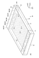
- FIG. 1 is a schematic diagram showing the configuration of the solid-state laser device in the first embodiment.
- the solid-state laser apparatus 1 according to the first embodiment is an apparatus that irradiates a solid-state laser using a solid as a medium.
- the solid state laser device 1 in the first embodiment is a slab type solid state laser irradiation device.
- the solid-state laser device 1 includes a solid-state laser amplification device 10, a storage chamber 12, a light emitting unit 100, and an irradiation unit 102.
- the light emitting unit 100 is an excitation light source of the laser light L, and is a laser diode, for example.
- the irradiation unit 102 is, for example, a laser irradiation head.
- the solid-state laser device 1 transmits and amplifies the laser light L excited by the light emitting unit 100 through the solid-state laser amplifying device 10 provided in the storage chamber 12, and irradiates the amplified laser light L from the irradiation unit 102. To do.
- the solid-state laser device 1 irradiates the laser beam L from the irradiation unit 102 and performs machining or the like. Note that the laser beam L emitted from the solid-state laser device 1 has a high output with a heat flux of 100 W / cm 2 or more, for example.
- the storage chamber 12 is a chamber in which the solid-state laser amplification device 10 is stored.
- the storage chamber 12 is a chamber sealed from the outside, and in use, the internal gas is exhausted by a pump or the like and is in a vacuum state.
- the storage chamber 12 is provided with an entrance window 13 and an exit window 14.
- the laser beam L from the light emitting unit 100 is transmitted through the entrance window 12 a to the inside, and the internal laser beam L is transmitted from the exit window to the irradiation unit 102. Let it emit.
- the solid-state laser amplifying apparatus 10 is a so-called slab type solid-state laser amplifying apparatus.
- the solid-state laser amplifying apparatus 10 includes a laser medium unit 20 and cooling units 30A, 30B, and 30C.
- the laser medium unit 20 is a slab type laser medium for amplifying the laser light L.
- the laser medium unit 20 is Nd: YAG ceramic in the present embodiment.
- Nd: YAG ceramics are obtained by doping a part of yttrium with neodymium in the process of producing YAG (Yttrium Aluminum Garnet) crystals.
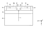
- the laser medium unit 20 includes a medium 22 and amplification layers 24A, 24B, and 24C.
- the medium 22 is a translucent crystal (solid) such as YAG, for example.
- the amplification layers 24 ⁇ / b> A, 24 ⁇ / b> B, and 24 ⁇ / b> C are layers provided on the surface of the medium 22, and are generated by doping a plate made of the same material as the medium 22 with ions such as yttrium.
- the amplification layers 24A, 24B, and 24C are gain media that amplify the laser light L.
- the medium 22 is a hexahedron (in this embodiment, a frustum).
- the length of the medium 22 along the direction X is longer than the length along the direction Y.
- the direction Y is a direction that intersects the direction X, and is a direction that is orthogonal to the direction X in the present embodiment.
- a direction Z described later is a direction intersecting with the direction X and the direction Y, and is a direction orthogonal to the direction X and the direction Y in the present embodiment.
- one surface along the direction Y is an upper bottom surface 22a on the side having a smaller area, and the other surface is a lower and lower surface 22b on the side having a larger area.
- the shape of the medium 22 is not limited to this.
- the amplification layers 24A and 24C are attached to the lower surface 22b with a predetermined interval along the direction X.
- the amplification layer 24B is attached to the upper bottom surface 22a.
- the amplification layer 24B is located along the direction X between the amplification layer 24A and the amplification layer 24C.
- a plurality of amplification layers may be attached at predetermined intervals similarly to the lower bottom surface 22b.
- the amplification layers 24A, 24B, and 24C are not distinguished, they are referred to as amplification layers 24. It can be said that the amplification layer 24 is provided on each of the surfaces (upper bottom surface 22a and lower bottom surface 24b) facing each other in the direction Y of the medium 22. Further, it can be said that a plurality of amplification layers 24 are provided on the surface of the medium 22 at a predetermined interval along the direction X. However, the amplification layer 24 may not be provided at a predetermined interval along the direction X, and may be provided over the entire upper bottom surface 22a and the lower bottom surface 24b.
- Laser light L is incident on the inside of the medium 22 from the incident portion 26 on the side surface of the medium 22.
- the laser beam L incident on the inside of the medium 22 enters the amplification layer 24.
- the laser beam L incident on the amplification layer 24 is amplified and reflected by the surface 25 which is the surface of the amplification layer 24 opposite to the medium 22.
- the laser beam L reflected by the surface 25 is incident again into the medium 22 from the amplification layer 24 and is emitted from the emitting portion 27 on the side surface opposite to the incident portion 26 along the direction X.
- the surface 25 may be provided with a reflective layer that totally reflects the laser light L.
- the incident laser beam L in the storage chamber 12 enters the amplification layer 24A from the incident unit 26 through the medium 22.
- the laser beam L incident on the amplification layer 24A is amplified and reflected, and enters the amplification layer 24B via the medium 22.
- the laser light L incident on the amplification layer 24B is amplified and reflected, and enters the amplification layer 24C via the medium 22.
- the laser beam L that has entered the amplification layer 24C is amplified and reflected, enters the medium 22, and is emitted from the emission unit 27 toward the outside (the storage chamber 12).
- the laser light L in the present embodiment proceeds zigzag in the direction X in the laser medium unit 20. Therefore, the direction X can also be referred to as the traveling direction of the laser light L.
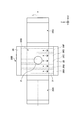
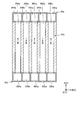
- FIG. 2 is a schematic diagram of a cooling unit in the first embodiment.
- the cooling unit 30 is a microchannel heat exchanger. As shown in FIG. 2, the cooling unit 30 includes a microchannel unit 31, an inlet header unit 32, and an outlet header unit 34.
- the microchannel portion 31 is a plate-like member having a plurality of cooling pipes 36A, 36B, 36C, 36D, and 36E opened therein.
- the cooling duct 36 extends along a direction A parallel to the cooling surface 35 that is the surface of the microchannel portion 31.
- the cooling duct 36 opens to one side surface 37 and the other side surface 38 of the microchannel portion 31 along the direction A, and conducts from one side surface 37 to the other side surface 38.
- the cooling surface 35 is provided on the outer periphery of the plurality of cooling pipes 36.
- the microchannel portion 31 is a metal member having a relatively high thermal conductivity such as aluminum or SUS (stainless steel), but the material is not limited thereto.
- the cooling pipes 36A, 36B, 36C, 36D, and 36E are arranged along a direction B that is a direction parallel to the cooling surface 35 of the microchannel portion 31 and intersecting the direction A.
- the cooling pipelines 36A, 36B, 36C, 36D, and 36E are arranged at equal intervals along the direction B, and the cooling pipeline 36C is located at the center along the direction B. Yes.
- the cooling pipes 36A, 36B, 36C, 36D, and 36E do not need to be arranged at equal intervals, and any number is possible as long as the number is plural.
- the inlet header portion 32 is a cylindrical member having a hollow inside.
- the inlet header portion 32 is attached to one side surface 37 of the microchannel portion 31.
- the inlet header 32 has an opening (not shown) for conducting the internal space with each of the plurality of cooling pipes 36, and an introduction opening 32H for introducing the cooling solvent W into the internal space. Yes.
- the outlet header 34 is a cylindrical member having a hollow inside.
- the outlet header portion 34 is attached to the other side surface 38 of the microchannel portion 31.
- the outlet header 34 has an opening (not shown) for connecting the internal space to each of the plurality of cooling pipes 36 and a lead-out opening 34H for leading the cooling solvent W from the internal space to the outside. is doing.
- the cooling unit 30 introduces the cooling solvent W into the inlet header portion 32 from the introduction opening 32H, distributes the cooling solvent W to each cooling pipe 36, and distributes the cooling solvent W in each cooling pipe 36.
- the microchannel unit 31 is in contact with the object to be cooled, and cools the object to be cooled by the cooling solvent W flowing through each cooling pipe 36.
- the cooling solvent W flowing in each cooling pipe 36 flows toward the outlet header portion 34.
- the cooling solvent W that has flowed into the outlet header portion 34 is led out to the outside through the outlet opening portion 34H, cooled outside, and introduced into the inlet header portion 32 again.
- the cooling solvent W in this embodiment is a liquid in the state introduce
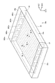
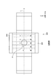
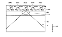
- FIG. 3 is a schematic view of the solid-state laser amplifier according to the first embodiment as viewed from above.
- the cooling unit 30 has a cooling surface 35 attached so as to contact the surface 25 of the amplification layer 24, and cools the amplification layer 24.
- the cooling unit 30A is attached to the amplification layer 24A.
- the cooling unit 30B is attached to the amplification layer 24B.
- the cooling unit 30C is attached to the amplification layer 24C. Therefore, it can be said that the cooling unit 30 is provided on each of the surfaces (the surface on the upper bottom surface 22a side and the surface on the lower bottom surface 24b side) facing each other in the direction Y of the laser medium unit 20.
- a plurality of cooling units 30 are provided on the surface of the laser medium unit 20 at a predetermined interval along the direction X. That is, the cooling unit 30 is provided only in the amplification layer 24 in the laser medium unit 20.
- the direction A in which the cooling pipes 36 extend is along the direction Z
- the direction B in which the plurality of cooling pipes 36 are arranged is along the direction X
- the direction C is along the direction Y.
- the attachment direction of the cooling unit 30 is not limited to this as long as the cooling surface 35 is attached to the surface 25 of the amplification layer 24.
- the direction A in which the cooling pipe 36 extends extends along the direction X. May be.
- the cooling unit 30 is connected to a cooling solvent cooling unit 60.
- the cooling solvent cooling unit 60 is provided outside the storage chamber 12, and introduces the cooling solvent W into the introduction opening 32 ⁇ / b> H of the inlet header unit 32 through the introduction pipe 62.
- the cooling solvent cooling unit 60 derives the cooling solvent W from the outlet opening 34 ⁇ / b> H of the outlet header 34 via the outlet pipe 64.
- the cooling solvent cooling part 60 cools the cooling solvent W from the outlet header part 34 and supplies it again to the inlet header part 32.
- the configuration of the cooling solvent cooling unit 60 is arbitrary as long as it cools the cooling solvent W.
- the cooling solvent cooling unit 60 may naturally cool by providing fins between a plurality of pipes through which the cooling solvent W is conducted. It may be forcibly cooled.
- the laser light L proceeds in a zigzag manner toward the direction X at the center position in the direction Z in the laser medium unit 20.
- the laser light L is reflected at the light receiving point P that is the center position in the direction X of the amplification layers 24A, 24B, and 24C. That is, it can be said that the light receiving portion P is a portion that receives (reflects) the laser light L on the surface 25 of the amplification layer 24.
- the amplification layer 24 is heated by the laser light L, and becomes the highest heat particularly at the light receiving point P. Then, the degree of heating of the amplification layer 24 decreases as the distance from the light receiving point P increases.
- the temperature of the amplification layer 24 increases as it approaches the light receiving point P along the direction parallel to the surface 25 (direction X and direction Z). That is, the temperature distribution of the amplification layer 24 is biased along the direction X, for example. When the temperature distribution is uneven, the performance of the laser beam L may be reduced.
- the cooling unit 30 is attached so that the direction B in which the plurality of cooling pipes 36 are arranged is along the direction X. That is, in the cooling unit 30, the cooling pipe 36 ⁇ / b> C is located at a location facing the light receiving location P that is the central position in the direction X of the amplification layer 24.
- the cooling unit 30 has cooling pipes 36 ⁇ / b> D and 36 ⁇ / b> E arranged in this order toward one direction away from the light receiving point P along the direction X, and the other side away from the light receiving point P along the direction X.
- the cooling pipes 36B and 36A are arranged in this order toward the direction.
- the cooling unit 30 increases the cooling power as the cooling pipe 36 is located closer to the light receiving point P. That is, in the first embodiment, the cooling unit 30 causes the cooling power of the cooling pipe 36 ⁇ / b> C that is provided (closest position) to face the light receiving spot P to a position farther from the light receiving spot P than the cooling pipe 36 ⁇ / b> C. It is larger than the cooling power of the provided cooling pipes 36A, 36B, 36D, 36E. In addition, the cooling unit 30 makes the cooling power of the cooling pipe 36B larger than that of the cooling pipe 36A provided at a position farther from the light receiving point P than the cooling pipe 36B.
- the cooling unit 30 makes the cooling power of the cooling pipe 36D larger than that of the cooling pipe 36E provided at a position farther from the light receiving point P than the cooling pipe 36D.
- the cooling power indicates the amount of heat that can be taken from the body to be cooled in heat exchange. When the cooling power is high, the amount of heat that can be taken from the body to be cooled increases.
- the cooling unit 30 can cool the portion where the temperature of the amplification layer 24 is high with higher cooling power by increasing the cooling power of the cooling pipe line 36 provided closer to the light receiving point P.
- the temperature distribution along the direction X of the layer 24 can be suppressed from being biased.
- the cooling unit 30 in the first embodiment increases the cooling power by increasing the flow rate of the cooling solvent W flowing in the cooling pipe 36 provided at a position closer to the light receiving point P. ing.
- the cooling unit 30 can increase the flow velocity by making the flow path cross-sectional area of the cooling pipe line 36C smaller than the others.
- this is because the cross-sectional area of the cooling pipe 36C as viewed from the direction C is reduced while the width along the direction C of the cooling pipe 36C is smaller than the other cooling pipes 36 to reduce the flow area. Can be realized by keeping the same.
- the cooling unit 30 is not limited to increasing the flow rate as long as the cooling power can be increased, and any configuration can be adopted.
- the cooling unit 30 can increase the cooling power by lowering the temperature of the cooling solvent W that flows into the cooling pipe 36 that is provided closer to the light receiving location P.
- the cooling unit 30 has the following structure, for example. That is, a partition is provided in the inlet header portion 32, and a space for supplying the cooling solvent W to the cooling pipe 36C and a space for supplying the cooling solvent W to the other cooling pipe 36 are separated and cooled.
- the cooling solvent W having a lower temperature is supplied only to the space for supplying the cooling solvent W to the pipe line 36C.
- the cooling unit 30 can increase the cooling power by increasing the heat transfer area to the amplification layer 24 as the cooling pipe 36 is located closer to the light receiving point P.
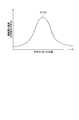
- FIG. 4 is a graph showing an example of the temperature distribution of the amplification layer.
- the horizontal axis in FIG. 4 indicates the position of the amplification layer 24 along the direction X, and indicates the temperature of the amplification layer 24.
- a curve S1 in FIG. 4 shows an example of a measurement result of the temperature distribution of the amplification layer 24 at each position along the direction X. As shown in the curve S1, in the example of FIG. 4, the temperature of the amplification layer 24 is highest at the center position (light receiving point P) along the direction X, and the temperature decreases in a curve as the distance from the center position increases. is doing.
- the cooling power of the cooling unit 30 may be determined based on this curve S1.
- the cooling power is determined so that the distribution of the cooling power of the cooling unit 30 (cooling power for each cooling pipe 36) becomes the curve S2 of FIG.
- a curve S2 is a curve when the vertical axis in FIG. 4 is the cooling power of the cooling unit 30, and shows an example of the temperature distribution of the cooling unit 30 (cooling pipe line 36) at each position along the direction X. .
- the gradient of the cooling power of the curve S2 is the same as the temperature gradient of the curve S1. In this way, by determining the cooling power based on the actual measurement result of the temperature distribution of the amplification layer, it is possible to more appropriately suppress the temperature distribution from being biased.
- the solid-state laser amplifying apparatus 10 includes the laser medium unit 20 including the medium 22 and the amplification layer 24, the plurality of cooling pipes 36, and the cooling surface 35.
- the medium 22 is a solid medium in which the laser beam L is incident from the incident unit 26 and the laser beam L is emitted to the outside from the emitting unit 27.
- the amplification layer 24 is provided on the surface of the medium 22, receives the laser light L in the medium 22, reflects the laser light L while amplifying it toward the emission unit 27.
- the plurality of cooling pipes 36 conduct the cooling solvent W therein and are arranged in a direction parallel to the surface 25 of the amplification layer 24.
- the cooling surface 35 is provided on the outer periphery of the cooling pipeline 36 and is attached to the surface 25 of the amplification layer 24.
- the cooling unit 30 increases the cooling power in the cooling pipe line 36 provided at a position closer to the position facing the position (light receiving position P) where the laser light L of the amplification layer 24 is received.
- This solid-state laser amplifying apparatus 10 increases the cooling power as the cooling pipe 36 is provided at a position closer to the position facing the position (light receiving position P) where the laser light L of the amplification layer 24 is received. Since this solid-state laser amplifying apparatus 10 can cool the light receiving portion P, which is a portion where the temperature of the amplification layer 24 is high, with a higher cooling power, the temperature distribution of the amplification layer 24 is suppressed from being biased, and the laser beam L performance degradation can be suppressed.
- a microchannel type cooling unit 30 is attached to the amplification layer 24. Accordingly, the heat of the amplification layer 24 is indirectly cooled by the cooling solvent W flowing in the cooling unit 30.
- the inside of the cooling chamber provided so as to cover the surface of the amplification layer 24 is pressurized, and liquid nitrogen is injected toward the surface of the amplification layer 24 in the cooling chamber. Therefore, it is necessary to perform cooling.
- the cooling chamber into which liquid nitrogen is jetted needs to be sealed for cooling.
- a sealing material is provided between the amplification layer 24 and the cooling chamber to seal from the outside.
- this solid-state laser amplifying apparatus 10 is indirectly cooled, for example, unlike direct cooling in which liquid nitrogen is injected, it is not necessary to perform sealing to cool the laser medium portion 20. Therefore, according to this solid-state laser amplifier 10, the laser medium unit 20 can be appropriately cooled.
- the cooling unit 30 increases the flow rate of the flowing cooling solvent W in the cooling pipe 36 provided at a position closer to the position facing the light receiving location P, or receives the light receiving location P.
- the temperature of the cooling solvent W that flows into the cooling pipe line 36 that is closer to the position opposite to the lower position of the cooling pipe W is lowered, so that the solid-state laser amplifier 10 is provided closer to the position facing the light receiving point P. Since the cooling power of the cooling channel 36 thus formed can be increased appropriately, the temperature distribution of the amplification layer 24 is appropriately suppressed from being biased.
- the solid-state laser amplifying apparatus 10a according to the second embodiment is different from the first embodiment in that the flow directions of the cooling solvent W between adjacent cooling pipes are opposite to each other.
- description of portions having the same configuration as that of the first embodiment is omitted.
- FIG. 5A and FIG. 5B are schematic views of a cooling unit according to the second embodiment.
- FIG. 5A is a schematic perspective view of the cooling unit 30a according to the second embodiment.
- FIG. 5B is a schematic cross-sectional view of the cooling unit 30a according to the second embodiment.
- the cooling unit 30a according to the second embodiment includes a microchannel unit 31a, a first header unit 32a, and a second header unit 34a.
- the microchannel portion 31a is a plate-like member having a plurality of cooling pipes 36Aa, 36Ba, 36Ca, 36Da, and 36Ea opened therein.
- cooling pipes 36Aa, 36Ba, 36Ca, 36Da, and 36Ea are the same as those in the first embodiment.
- the cooling pipes 36Aa, 36Ba, 36Ca, 36Da, and 36Ea do not have to have the same cooling power as in the first embodiment, and may have the same cooling power.
- cooling pipes 36Aa, 36Ba, 36Ca, 36Da, and 36Ea are not distinguished from each other, they are referred to as cooling pipes 36a.
- the first header portion 32a is a cylindrical member having a hollow inside.
- the first header portion 32a is attached to one side surface 37 of the microchannel portion 31a.
- the first header portion 32a has an internal space partitioned into spaces 32Aa, 32Ba, 32Ca, 32Da, and 32Ea by a plurality of partitions.
- Each of the spaces 32Aa, 32Ba, 32Ca, 32Da, and 32Ea is provided with an opening through which the cooling solvent cooling unit 60 and the cooling solvent W are circulated.
- the second header portion 34a is a cylindrical member having a hollow inside.
- the second header portion 34a is attached to the other side surface 38 of the microchannel portion 31a.
- the second header portion 34a has an internal space partitioned into spaces 34Aa, 34Ba, 34Ca, 34Da, and 34Ea by a plurality of partitions.
- the spaces 34Aa, 34Ba, 34Ca, 34Da, and 34Ea are provided with openings through which the cooling solvent cooling unit 60 and the cooling solvent W circulate.
- the flow directions of the cooling solvent W between adjacent cooling pipes 36a are opposite to each other.
- the cooling solvent W flows through the cooling pipes 36Aa, 36Ca, 36Ea from the space 32Aa toward the space 34Aa.
- the cooling pipes 36Ba and 36Da the cooling solvent W flows from the space 34Ba toward the space 32Ba.
- the cooling pipeline 36a may be configured so that the direction in which the cooling solvent W flows in some cooling pipelines 36a is opposite to the direction in which the cooling solvent W flows in other cooling pipelines 36a. There may be one in which the flow direction of the cooling solvent W between the adjacent cooling pipes 36a is not reversed.
- the cooling solvent W flows in the cooling pipes 36Aa, 36Ba, and 36Ea from the space 32Aa toward the space 34Aa, and the cooling pipes 36Ca and 36Da flow in the cooling solvent W from the space 34Ba toward the space 32Ba.
- the cooling unit 30a can prevent the temperature distribution of the amplification layer 24 from being biased by changing the direction of the cooling solvent W flowing through the cooling pipe 36a in this way.
- a description will be given using a comparative example.
- FIG. 6 is an explanatory diagram for explaining cooling of the cooling unit according to the comparative example.
- FIG. 7 is an explanatory diagram illustrating cooling of the cooling unit according to the second embodiment.
- the cooling solvent W flows from the inlet header part 32X toward the outlet header part 34X in all the cooling pipes, and the flow direction is the same. Yes.
- the cooling power of the cooling pipes is equal to each other.
- the amplification layer 24 also exhibits a temperature distribution corresponding to the cooling solvent W, the temperature of the amplification layer 24 on the outlet header portion 34X side is higher than the temperature on the inlet header portion 32X side. That is, in the comparative example, the temperature distribution of the amplification layer 24 may be biased.
- the flow direction of the cooling solvent W in the cooling pipe 36a is staggered.
- the temperature of the cooling solvent W flowing through the cooling pipes 36Aa, 36Ca, 36Ea rises from the first header portion 32a toward the second header portion 34a.
- the temperature of the cooling solvent W flowing through the cooling pipes 36Ba and 36Da rises from the second header portion 34a toward the first header portion 32a.
- the cooling unit 30a changes the direction in which the cooling solvent W flows in some cooling pipes 36a and the cooling solvent in other cooling pipes 36a.
- the directions in which the cooling solvent W flows between the adjacent cooling pipes 36a are opposite to each other. Therefore, the solid-state laser amplifying apparatus 10a according to the second embodiment can more appropriately suppress the temperature distribution of the amplification layer 24 from being biased.
- the solid-state laser amplifying apparatus 10b according to the third embodiment differs from the first embodiment in the shape of the cooling pipe.
- description of portions having the same configuration as that of the first embodiment is omitted.
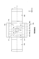
- FIG. 8 is a schematic diagram of a cooling unit according to the third embodiment.
- the cooling unit 30 b according to the third embodiment includes a microchannel unit 31 b, an inlet header unit 32, and an outlet header unit 34.
- the microchannel portion 31b is a plate-like member having a plurality of cooling pipes 36Ab, 36Bb, 36Cb, 36Db, and 36Eb opened therein.
- the cooling pipelines 36Ab, 36Bb, 36Cb, 36Db, and 36Eb may have different cooling power as in the first embodiment, or may have the same cooling power.
- cooling pipes 36Ab, 36Bb, 36Cb, 36Db, and 36Eb are not distinguished from each other, they are referred to as cooling pipes 36b.
- the cooling pipeline 36 b has an inlet pipeline 41, a first pipeline 42, a second pipeline 43, and an outlet pipeline 44.
- the inlet conduit 41 is a conduit extending along the direction A from one side surface 37 of the microchannel portion 31 b and is provided in the vicinity of the surface on the opposite side of the cooling surface 35.
- the first pipeline 42 is a pipeline connected to the inlet pipeline 41, and extends in the direction approaching the cooling surface 35 in the direction C to the vicinity of the cooling surface 35.
- the second pipeline 43 is connected to the first pipeline 42 and is a pipeline through which the cooling solvent W from the first pipeline 42 flows.
- the second duct 43 extends to the vicinity of the surface on the opposite side of the cooling surface 35 in the direction away from the cooling surface 35 in the direction opposite to the direction C.
- the outlet conduit 44 is a conduit connected to the second conduit 43 and extends along the direction A to the other side surface 38 of the microchannel portion 31b.
- the outlet pipe 44 is also provided in the vicinity of the surface opposite to the cooling surface 35. Further, the first pipeline 42 and the second pipeline 43 are provided along the direction A at the center of the microchannel portion 31b.
- the cooling solvent W from the inlet header portion 32 flows in the order of the inlet pipe 41, the first pipe 42, the second pipe 43, and the outlet pipe 44.
- the cooling solvent W flowing through the inlet line 41 is referred to as a cooling solvent W1
- the cooling solvent W flowing through the first line 42 is referred to as a cooling solvent W2
- the cooling solvent W flowing through the second line 43 is referred to as a cooling solvent W3.
- the cooling solvent W flowing through the outlet pipe 44 is referred to as a cooling solvent W4.
- the cooling solvent W1 flows in the inlet pipe line 41 along the direction A and at a position away from the cooling surface 35 (near the surface opposite to the cooling surface 35).
- the cooling solvent W2 flows through the first pipeline 42 in the direction approaching the cooling surface 35 in the direction C to the vicinity of the cooling surface 35.
- the cooling solvent W3 flows through the second conduit 43 in the direction away from the cooling surface 35 in the direction opposite to the direction C to the vicinity of the surface opposite to the cooling surface 35.
- the cooling solvent W4 flows in the outlet pipe 44 along the direction A and at a position away from the cooling surface 35 (near the surface opposite to the cooling surface 35).
- the cooling unit 30b can suppress the temperature distribution of the amplification layer 24 from being biased because the cooling solvents W1, W2, W3, and W4 flow through the cooling pipes 36b as described above. This will be specifically described below.
- FIGS. 9A to 9C are explanatory diagrams for explaining cooling of the cooling unit according to the third embodiment.
- 9A is a schematic view of the cooling unit 30b as viewed from the top
- FIG. 9B is a schematic view of the cooling unit 30b as viewed from the front
- FIG. 9C is a schematic view of the cooling unit 30b as viewed from the side.
- the inlet conduit 41 is located on one end face side in the direction Z from the center position (light receiving point P) of the amplification layer 24.
- the outlet pipe 44 is located on the other end face side along the direction Z from the center position (light receiving point P) of the amplification layer 24.
- the first pipe line 42 and the second pipe line 43 are arranged along the direction Z at positions facing the center position (light receiving point P) of the amplification layer 24.
- the cooling unit 30b cools the amplification layer 24 with cooling solvents W2 and W3 flowing in the direction (direction Y) perpendicular to the cooling surface 35 in the vicinity of the light receiving portion P. Accordingly, the temperature of the cooling solvent W4 downstream from the cooling solvents W2 and W3 is higher than the temperature of the upstream cooling solvent W1.
- the inlet pipe 41 and the outlet pipe 44 are located away from the cooling surface 35.
- the cooling unit 30b can suppress the influence of the temperature gradient of the cooling solvents W1 and W4 flowing along the direction (direction Z) parallel to the cooling surface 35 from being transmitted to the opposing amplification layer 24, and the amplification. It becomes possible to make the temperature distribution of the layer 24 more uniform than the above-mentioned comparative example.
- the plurality of cooling pipes 36b extends to the first pipe 42 and the first pipe 42 extending in the direction approaching the cooling surface 35. And a second conduit 43 that extends in a direction away from the cooling surface 35 and through which the cooling solvent W from the first conduit 42 flows.
- the cooling section 30b is not a cooling solvent W (cooling solvents W1, W4) that flows in a direction parallel to the cooling surface 35 (direction Z), but a first pipe that flows in a direction (direction Y) perpendicular to the cooling surface 35.
- the amplification layer 24 is cooled by the cooling solvents W2 and W3 in the passage 42 and the second pipeline 43. Therefore, according to this solid-state laser amplification device 10b, it is possible to suppress the influence of the temperature gradient of the cooling solvent W from being transmitted to the amplification layer 24, and to suppress the temperature distribution of the amplification layer 24 from being biased.
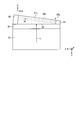
- FIG. 10 is a schematic diagram illustrating a configuration of a cooling unit according to another example of the third embodiment.
- the configuration of the cooling unit is not limited to that described in the first to third embodiments, and may be a configuration such as the cooling unit 30c shown below, for example.
- the cooling unit 30 c changes the distance between the cooling pipe line 36 c and the cooling surface 35 along the direction Z.
- FIG. 10 is a schematic view of the cooling unit 30c as viewed from the side. As shown in FIG. 10, the cooling part 30c changes the length (thickness) of the microchannel part 31c along the direction C along the direction A in which the cooling pipe line 36c extends. The thickness of the microchannel portion 31c decreases from the inlet header portion 32 side toward the outlet header side.
- the cooling pipe 36c extends linearly along the direction A. Accordingly, the cooling pipe 36 c is closer to the cooling surface 35 in the direction Z from the upstream side of the cooling solvent W toward the downstream side of the cooling solvent W.
- the temperature distribution of the amplification layer 24 is also biased by changing the distance between the cooling pipe 36c and the cooling surface 35 along the direction Z, as in the second and third embodiments. This can be suppressed.
- changing the distance between the cooling pipe line 36c and the cooling surface 35 it is not restricted to the example of FIG. 10, For example, it goes to the downstream of the cooling solvent W from the upstream of the cooling solvent W along the direction Z. Accordingly, the distance from the cooling surface 35 may be increased.
- the solid-state laser amplifying apparatus 10d according to the modified example is different from the first embodiment in that the solid-state laser amplifying apparatus 10d includes a heat conduction unit that transfers heat of the amplification layer 24 to the cooling unit 30 between the amplification layer 24 and the cooling unit 30. Different. In the modification, the description of the parts having the same configuration as that of the first embodiment is omitted.
- FIG. 11 is a schematic diagram showing a configuration of a solid-state laser device in a modified example.
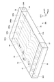
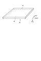
- FIG. 12 is a schematic diagram illustrating the shape of the heat conducting unit.
- the solid-state laser amplification device 10 d includes heat conducting units 50 ⁇ / b> A, 50 ⁇ / b> B, and 50 ⁇ / b> C.
- the heat conduction parts 50A, 50B, and 50C are not distinguished from each other, they are referred to as the heat conduction part 50.
- the heat conducting unit 50 is a plate-like member having a high thermal conductivity, is provided in contact between the amplification layer 24 and the cooling unit 30, and the heat of the amplification layer 24. The heat is transferred to the cooling unit 30.
- the heat conducting unit 50 is provided in close contact between the amplification layer 24 and the cooling unit 30.
- one surface 52 is in contact with the surface 25 of the amplification layer 24A, and the other surface 54 is in contact with the cooling surface 35 of the cooling unit 30A.
- the heat conducting unit 50 is provided on each of the surfaces (the surface on the upper bottom surface 22a side and the surface on the lower bottom surface 24b side) facing each other along the direction Y of the laser medium unit 20.
- a plurality of the heat conducting units 50 are provided on the surface of the laser medium unit 20 at a predetermined interval along the direction X.
- the heat conducting unit 50 is provided only in the amplification layer 24 that receives the laser beam L and becomes high temperature in the laser medium unit 20.
- the heat conducting unit 50 is made of a material having a higher thermal conductivity than the laser medium unit 20 and the cooling unit 30, and is a pitch-type CFRP (Carbon Fiber Reinforced Plastics carbon fiber reinforced plastic) in this embodiment.
- the heat conducting unit 50 extends along the directions D and E that are parallel to the surfaces (one surface 52 and the other surface 54), and is predetermined along the direction F that is perpendicular to the surface. It has the thickness of.
- the thickness along the direction F of the heat conducting unit 50 in the present embodiment is 0.1 mm or more and 1 mm or less, but is not limited thereto.
- the heat conduction unit 50 in this modification is oriented along the direction in which the fiber direction is parallel to the surface (for example, directions D and E), and has anisotropy in heat conductivity.
- the thermal conductivity along the direction D and the direction E is higher than the thermal conductivity along the direction F. That is, the heat conducting unit 50 is more likely to transmit heat in the direction along the direction D and the direction E than in the direction F.
- the heat conducting unit 50 is attached such that one surface 52 is in contact with the surface 25 of the amplification layer 24 and the other surface 54 is in contact with the cooling surface 35 of the cooling unit 30.
- the heat conducting unit 50 is attached so that the direction D is parallel to the direction X, the direction E is parallel to the direction Z, and the direction F is parallel to the direction Y.
- the attachment direction is not restricted to this.
- the solid-state laser amplifying apparatus 10d includes a heat conducting unit 50 that is provided in contact with the amplifying layer 24 and the cooling surface 35 and transfers heat of the amplifying layer 24 to the cooling unit 30.
- This solid-state laser amplifying apparatus 10 d conducts heat to the cooling unit 30 via the heat conducting unit 50. Therefore, the solid-state laser amplification device 10d can efficiently transfer the heat of the amplification layer 24 to the cooling unit 30, and can cool the amplification layer 24 more appropriately.
- the heat conducting unit 50 in the present modification is a pitch-type CFRP
- the heat conductivity is high, and the heat of the amplification layer 24 can be transmitted to the cooling unit 30 more efficiently.
- the heat conduction part 50 has a heat conductivity along a direction (directions D and E) parallel to one surface 52, and a heat conductivity along a direction (direction F) perpendicular to the one surface 52. high. Therefore, the solid-state laser amplifying apparatus 10 d can diffuse the heat of the amplification layer 24 toward the surface of the heat conducting unit 50 and cool the heat on the entire cooling surface 35 of the cooling unit 30. Therefore, the heat conducting unit 50 can cool the amplification layer 24 more appropriately.
- the solid-state laser amplification device 10d diffuses the heat of the amplification layer 24 toward the surface of the heat conducting unit 50, the heat of the amplification layer 24 is made uniform along the surface, and the temperature distribution in the laser medium unit 20 is It is also possible to suppress the bias.
- the heat conductivity along the direction (direction F) perpendicular to the one surface 52 is higher than the heat conductivity along the direction (directions D and E) parallel to the one surface 52. It may be high.
- the fiber direction of CFRP is oriented along a direction (direction F) perpendicular to one surface 52. Since the heat conducting unit 50 can quickly transfer heat in the direction E, that is, in the direction from the amplification layer 24 to the cooling unit 30, the amplification layer 24 can be cooled more quickly.
- the material of the heat conducting unit 50 is not limited to pitch type CFRP, and may be, for example, a graphite sheet.
- the graphite sheet is a sheet containing graphite (graphite). This graphite sheet is formed by laminating a graphite layer extending along the directions D and E along the direction F, and thus along a direction parallel to the one surface 52 (directions D and E). The thermal conductivity can be made higher than the thermal conductivity along the direction perpendicular to the one surface 52 (direction F). Further, the graphite sheet is formed by laminating graphite layers extending along the direction F along the direction D or the direction E, so that the graphite sheet extends along a direction perpendicular to the one surface 52 (direction F). The thermal conductivity can be higher than the thermal conductivity along the direction (directions D and E) parallel to the one surface 52.
- heat conducting unit 50 according to this modification can be applied to any of the solid-state laser amplifying devices of the first to third embodiments.
Landscapes
- Physics & Mathematics (AREA)
- Electromagnetism (AREA)
- Engineering & Computer Science (AREA)
- Plasma & Fusion (AREA)
- Optics & Photonics (AREA)
- Chemical & Material Sciences (AREA)
- Crystallography & Structural Chemistry (AREA)
- Lasers (AREA)
Priority Applications (2)
| Application Number | Priority Date | Filing Date | Title |
|---|---|---|---|
| EP16855134.9A EP3300189B1 (en) | 2015-10-16 | 2016-06-08 | Solid laser amplification device |
| US15/578,301 US10236655B2 (en) | 2015-10-16 | 2016-06-08 | Solid laser amplification device |
Applications Claiming Priority (2)
| Application Number | Priority Date | Filing Date | Title |
|---|---|---|---|
| JP2015204803A JP6560954B2 (ja) | 2015-10-16 | 2015-10-16 | 固体レーザ増幅装置 |
| JP2015-204803 | 2015-10-16 |
Publications (1)
| Publication Number | Publication Date |
|---|---|
| WO2017064880A1 true WO2017064880A1 (ja) | 2017-04-20 |
Family
ID=58518212
Family Applications (1)
| Application Number | Title | Priority Date | Filing Date |
|---|---|---|---|
| PCT/JP2016/067059 Ceased WO2017064880A1 (ja) | 2015-10-16 | 2016-06-08 | 固体レーザ増幅装置 |
Country Status (4)
| Country | Link |
|---|---|
| US (1) | US10236655B2 (enExample) |
| EP (1) | EP3300189B1 (enExample) |
| JP (1) | JP6560954B2 (enExample) |
| WO (1) | WO2017064880A1 (enExample) |
Families Citing this family (2)
| Publication number | Priority date | Publication date | Assignee | Title |
|---|---|---|---|---|
| JP7086720B2 (ja) * | 2018-05-30 | 2022-06-20 | 浜松ホトニクス株式会社 | レーザ装置 |
| JP7341673B2 (ja) | 2019-02-27 | 2023-09-11 | 三菱重工業株式会社 | レーザ装置 |
Citations (5)
| Publication number | Priority date | Publication date | Assignee | Title |
|---|---|---|---|---|
| JPS4815599B1 (enExample) * | 1969-04-17 | 1973-05-16 | ||
| JPH08191167A (ja) * | 1995-01-11 | 1996-07-23 | Miyachi Technos Corp | レーザ装置 |
| JP2001015844A (ja) * | 1999-06-30 | 2001-01-19 | Saifasha:Yugen | 固体レーザ装置 |
| JP2001501776A (ja) * | 1996-05-31 | 2001-02-06 | ディーピーエスエス レイザーズ,インコーポレイテッド | イントラキャビティ3重化固体ダイオードポンピングレーザ |
| JP2014022568A (ja) * | 2012-07-18 | 2014-02-03 | Osaka Univ | レーザ媒質ユニット、レーザ増幅器及びレーザ発振器並びに冷却方法 |
Family Cites Families (8)
| Publication number | Priority date | Publication date | Assignee | Title |
|---|---|---|---|---|
| JPH09181376A (ja) * | 1995-12-26 | 1997-07-11 | Mitsubishi Heavy Ind Ltd | 固体レーザ励起用半導体レーザ及びその製造方法 |
| US6339605B1 (en) | 2000-02-16 | 2002-01-15 | The Boeing Company | Active mirror amplifier system and method for a high-average power laser system |
| US6625193B2 (en) | 2001-01-22 | 2003-09-23 | The Boeing Company | Side-pumped active mirror solid-state laser for high-average power |
| US20050189647A1 (en) | 2002-10-11 | 2005-09-01 | Chien-Min Sung | Carbonaceous composite heat spreader and associated methods |
| US20060083276A1 (en) | 2004-09-28 | 2006-04-20 | Snake Creek Lasers, Llc. | Cryogenically cooled solid state lasers |
| US7430230B2 (en) | 2005-04-07 | 2008-09-30 | The Boeing Company | Tube solid-state laser |
| JP2010034413A (ja) | 2008-07-30 | 2010-02-12 | Hamamatsu Photonics Kk | 固体レーザ装置 |
| FR2969402B1 (fr) | 2010-12-17 | 2013-02-15 | Fibercryst | Module a gain laser et methode de fabrication d'un tel module |
-
2015
- 2015-10-16 JP JP2015204803A patent/JP6560954B2/ja active Active
-
2016
- 2016-06-08 US US15/578,301 patent/US10236655B2/en active Active
- 2016-06-08 EP EP16855134.9A patent/EP3300189B1/en active Active
- 2016-06-08 WO PCT/JP2016/067059 patent/WO2017064880A1/ja not_active Ceased
Patent Citations (5)
| Publication number | Priority date | Publication date | Assignee | Title |
|---|---|---|---|---|
| JPS4815599B1 (enExample) * | 1969-04-17 | 1973-05-16 | ||
| JPH08191167A (ja) * | 1995-01-11 | 1996-07-23 | Miyachi Technos Corp | レーザ装置 |
| JP2001501776A (ja) * | 1996-05-31 | 2001-02-06 | ディーピーエスエス レイザーズ,インコーポレイテッド | イントラキャビティ3重化固体ダイオードポンピングレーザ |
| JP2001015844A (ja) * | 1999-06-30 | 2001-01-19 | Saifasha:Yugen | 固体レーザ装置 |
| JP2014022568A (ja) * | 2012-07-18 | 2014-02-03 | Osaka Univ | レーザ媒質ユニット、レーザ増幅器及びレーザ発振器並びに冷却方法 |
Non-Patent Citations (1)
| Title |
|---|
| See also references of EP3300189A4 * |
Also Published As
| Publication number | Publication date |
|---|---|
| US10236655B2 (en) | 2019-03-19 |
| JP2017076751A (ja) | 2017-04-20 |
| EP3300189A1 (en) | 2018-03-28 |
| EP3300189A4 (en) | 2018-10-10 |
| US20180145474A1 (en) | 2018-05-24 |
| EP3300189B1 (en) | 2021-09-22 |
| JP6560954B2 (ja) | 2019-08-14 |
Similar Documents
| Publication | Publication Date | Title |
|---|---|---|
| CN109244824B (zh) | Ld模块冷却装置和激光装置 | |
| JP6560954B2 (ja) | 固体レーザ増幅装置 | |
| JP2010114162A (ja) | レーザ利得媒質、レーザ発振器及びレーザ増幅器 | |
| US10663845B2 (en) | Color wheel device and projector | |
| CN115579715B (zh) | 光学元件、冷却装置和方法、冷却流道结构及其制造方法 | |
| CN113937615A (zh) | 用于激光器的冷却组件及冷却方法 | |
| EP4661610A1 (en) | Heat dissipation device | |
| US20160164241A1 (en) | System and method for cooling a laser gain medium using an ultra-thin liquid thermal optical interface | |
| JP2009253074A (ja) | レーザ光出射装置およびレーザ装置 | |
| JP6632315B2 (ja) | 固体レーザ増幅装置 | |
| CN103650260B (zh) | 具有热交换器的气体激光器 | |
| JP2018526829A (ja) | レーザー・システム又は他のシステム及び関連するデバイスで使用するウェーブガイドを形成するための技術 | |
| US20070189346A1 (en) | Solid-state laser apparatus | |
| JP2008300447A (ja) | 放熱装置 | |
| JP2002353551A (ja) | 半導体レーザ装置 | |
| JP2025020763A (ja) | コールドプレートおよびコールドプレートの製造方法 | |
| CN104362495A (zh) | 一种板条激光放大器及其激光输出方法 | |
| JP2008021879A (ja) | 端面励起微細ロッド型レーザ利得モジュール | |
| CN108351092A (zh) | 发光元件光源模块 | |
| JP6444053B2 (ja) | レーザ受光装置及びレーザ加工ユニット | |
| US20240344772A1 (en) | Heat sink apparatus | |
| JP2002359418A (ja) | 固体レーザーのスラブ冷却装置及び方法 | |
| CN112782822A (zh) | 一种激光通道冷却结构及冷却方法 | |
| JP2013044044A (ja) | アレイアンテナ式のcvdプラズマ装置 | |
| RU2614079C2 (ru) | Квантрон с диодной накачкой |
Legal Events
| Date | Code | Title | Description |
|---|---|---|---|
| 121 | Ep: the epo has been informed by wipo that ep was designated in this application |
Ref document number: 16855134 Country of ref document: EP Kind code of ref document: A1 |
|
| WWE | Wipo information: entry into national phase |
Ref document number: 15578301 Country of ref document: US |
|
| WWE | Wipo information: entry into national phase |
Ref document number: 2016855134 Country of ref document: EP |
|
| NENP | Non-entry into the national phase |
Ref country code: DE |