WO2017061592A1 - 圧電素子、圧電アクチュエータおよび圧電トランス - Google Patents
圧電素子、圧電アクチュエータおよび圧電トランス Download PDFInfo
- Publication number
- WO2017061592A1 WO2017061592A1 PCT/JP2016/079923 JP2016079923W WO2017061592A1 WO 2017061592 A1 WO2017061592 A1 WO 2017061592A1 JP 2016079923 W JP2016079923 W JP 2016079923W WO 2017061592 A1 WO2017061592 A1 WO 2017061592A1
- Authority
- WO
- WIPO (PCT)
- Prior art keywords
- piezoelectric
- electrode
- piezoelectric element
- migration
- internal electrodes
- Prior art date
- Legal status (The legal status is an assumption and is not a legal conclusion. Google has not performed a legal analysis and makes no representation as to the accuracy of the status listed.)
- Ceased
Links
Images






Classifications
-
- H—ELECTRICITY
- H10—SEMICONDUCTOR DEVICES; ELECTRIC SOLID-STATE DEVICES NOT OTHERWISE PROVIDED FOR
- H10N—ELECTRIC SOLID-STATE DEVICES NOT OTHERWISE PROVIDED FOR
- H10N30/00—Piezoelectric or electrostrictive devices
- H10N30/80—Constructional details
- H10N30/87—Electrodes or interconnections, e.g. leads or terminals
- H10N30/872—Interconnections, e.g. connection electrodes of multilayer piezoelectric or electrostrictive devices
-
- H—ELECTRICITY
- H10—SEMICONDUCTOR DEVICES; ELECTRIC SOLID-STATE DEVICES NOT OTHERWISE PROVIDED FOR
- H10N—ELECTRIC SOLID-STATE DEVICES NOT OTHERWISE PROVIDED FOR
- H10N30/00—Piezoelectric or electrostrictive devices
- H10N30/01—Manufacture or treatment
- H10N30/05—Manufacture of multilayered piezoelectric or electrostrictive devices, or parts thereof, e.g. by stacking piezoelectric bodies and electrodes
-
- H—ELECTRICITY
- H10—SEMICONDUCTOR DEVICES; ELECTRIC SOLID-STATE DEVICES NOT OTHERWISE PROVIDED FOR
- H10N—ELECTRIC SOLID-STATE DEVICES NOT OTHERWISE PROVIDED FOR
- H10N30/00—Piezoelectric or electrostrictive devices
- H10N30/20—Piezoelectric or electrostrictive devices with electrical input and mechanical output, e.g. functioning as actuators or vibrators
-
- H—ELECTRICITY
- H10—SEMICONDUCTOR DEVICES; ELECTRIC SOLID-STATE DEVICES NOT OTHERWISE PROVIDED FOR
- H10N—ELECTRIC SOLID-STATE DEVICES NOT OTHERWISE PROVIDED FOR
- H10N30/00—Piezoelectric or electrostrictive devices
- H10N30/40—Piezoelectric or electrostrictive devices with electrical input and electrical output, e.g. functioning as transformers
-
- H—ELECTRICITY
- H10—SEMICONDUCTOR DEVICES; ELECTRIC SOLID-STATE DEVICES NOT OTHERWISE PROVIDED FOR
- H10N—ELECTRIC SOLID-STATE DEVICES NOT OTHERWISE PROVIDED FOR
- H10N30/00—Piezoelectric or electrostrictive devices
- H10N30/80—Constructional details
- H10N30/85—Piezoelectric or electrostrictive active materials
- H10N30/853—Ceramic compositions
-
- H—ELECTRICITY
- H10—SEMICONDUCTOR DEVICES; ELECTRIC SOLID-STATE DEVICES NOT OTHERWISE PROVIDED FOR
- H10N—ELECTRIC SOLID-STATE DEVICES NOT OTHERWISE PROVIDED FOR
- H10N30/00—Piezoelectric or electrostrictive devices
- H10N30/80—Constructional details
- H10N30/87—Electrodes or interconnections, e.g. leads or terminals
- H10N30/871—Single-layered electrodes of multilayer piezoelectric or electrostrictive devices, e.g. internal electrodes
-
- H—ELECTRICITY
- H10—SEMICONDUCTOR DEVICES; ELECTRIC SOLID-STATE DEVICES NOT OTHERWISE PROVIDED FOR
- H10N—ELECTRIC SOLID-STATE DEVICES NOT OTHERWISE PROVIDED FOR
- H10N30/00—Piezoelectric or electrostrictive devices
- H10N30/80—Constructional details
- H10N30/87—Electrodes or interconnections, e.g. leads or terminals
- H10N30/877—Conductive materials
Definitions
- the present invention relates to a laminated piezoelectric element, a piezoelectric actuator, and a piezoelectric transformer that expand and contract when a voltage is applied.
- materials mainly composed of Ag such as Ag (silver) or Ag / Pd (silver palladium), are often used for the electrodes of piezoelectric elements from the viewpoint of characteristics and ease of use.
- Such an electrode material mainly composed of silver has a problem that Ag causes migration and deterioration of insulation.
- Patent Document 1 describes a piezoelectric element in which a stress relaxation layer is formed of a material to which a hardening element is added, and the mobility of metal cations and halogen anions in the stress relaxation layer is reduced.
- Patent Document 2 discloses that the change of the electric resistance value of the heating resistor is suppressed to be small by the migration-preventing conductor pattern that captures impurity elements such as Na, Mg, K, Ca and oxygen ions to be migrated. A ceramic heater for preventing heat generation is described.
- JP 2014-187061 A Japanese Utility Model Publication No. 5-43495
- the present invention has been made in view of such circumstances, and by preventing migration of Ag, a piezoelectric element, a piezoelectric actuator, a piezoelectric transformer, and an electrode material that can extend the life while maintaining good characteristics for a long period of time.
- the purpose is to provide.
- the piezoelectric element of the present invention is a stacked piezoelectric element that expands and contracts when a voltage is applied, and is connected to an external electrode provided on the surface of the element body and the external electrode.
- the electrode material used for the internal electrode or the external electrode is composed of Ag / Pd in a weight ratio of 60/40 to 85/15. It is characterized by containing 0.1 wt% to 10 wt% Pt with respect to the base material.
- the piezoelectric element of the present invention is characterized in that the electrode material contains 0.5 wt% to 5.0 wt% of Pt. Thereby, the effect of preventing Ag migration can be further improved.
- the piezoelectric element of the present invention is characterized in that the interval between the internal electrodes is 30 ⁇ m to 500 ⁇ m. Thereby, the piezoelectric element can prevent Ag migration while improving the characteristics.
- the piezoelectric actuator of the present invention includes an actuator body formed by connecting the piezoelectric elements described in (1) or (2) in series and a lead for electrically connecting the connected piezoelectric elements. And a member. Thereby, a highly durable piezoelectric actuator can be realized.
- the piezoelectric transformer of the present invention includes the piezoelectric element according to claim 1 or 2, wherein the voltage input from the primary side is stepped up or stepped down and output from the secondary side. . Thereby, the piezoelectric transformer which can maintain the outstanding performance is realizable.
- (A), (b), (c) is the perspective view and side sectional view which respectively show the piezoelectric element of this invention, and the side sectional view which shows a piezoelectric actuator. It is a perspective view which shows the piezoelectric element of this invention. It is a table
- piezoelectric element for piezoelectric actuator 1A and 1B are a perspective view and a side sectional view showing the piezoelectric element 100.
- FIG. In the stacked piezoelectric element 100 formed in a rectangular body, the piezoelectric layers 103 and the internal electrodes 104 and 105 are alternately stacked in the stacking direction Z, and expand and contract by applying a voltage to the internal electrodes 104 and 105.
- the piezoelectric layer 103 is made of a piezoelectric material such as PZT, for example, and is polarized in alternate directions in the thickness direction.
- the internal electrodes 104 and 105 are taken out on the opposing element side surfaces and connected to the external electrodes 106 and 107, respectively, and different voltages can be applied from the external electrodes 106 and 107 to the adjacent internal electrodes 104 and 105.
- each piezoelectric layer 103 expands and contracts, and the entire piezoelectric element expands and contracts.
- the piezoelectric element 100 is not limited to a rectangular body, and can take various forms.
- the electrode material used for the internal electrodes 104, 105 or the external electrodes 106, 107 is based on Ag (silver) / Pd (palladium) and contains 0.1 wt% to 10 wt% of Pt (platinum).
- Ag silver
- Pd palladium
- Pt platinum
- Ag / Pd having a weight ratio of 60/40 to 85/15 is preferably used as the base material of the electrode material.
- the component contained in the electrode is preferably Pt, but Ru (ruthenium), Rh (rhodium), Os (osmium), and Ir (iridium) may be contained instead of Pt.
- the electrode material contains 0.5 wt% to 5.0 wt% of Pt.
- the effect of preventing Ag migration can be further improved.
- Such a configuration is particularly effective when the distance between the internal electrodes 104 and 105 is 30 ⁇ m to 500 ⁇ m. Thereby, the piezoelectric element 100 can prevent Ag migration while improving the characteristics.
- FIG. 1C is a side sectional view showing the piezoelectric actuator 190.
- the piezoelectric actuator 190 is a piezoelectric actuator 190 for a positioner, and is formed by fitting the piezoelectric actuator body 110 into a cap 160 and sealing it. In FIG. 1C, only the cap 160 is shown in cross section, and the piezoelectric actuator body 110 is shown in a side view.
- the piezoelectric actuator body 110 is formed by bonding the piezoelectric elements 100 in series in the stacking direction Z.
- the lead members 121 and 122 are made of metal, are bonded to the external electrodes 106 and 107, respectively, and are connected to the terminals 151 and 152 at the seat 140, respectively.
- the piezoelectric actuator 190 when a voltage is applied to the terminals 151 and 152, the piezoelectric actuator main body 110 expands and contracts, and the cap 160 that contacts the chip 130 contacts a driven body such as a stage. As a result, the driven driven body can be precisely aligned. In this way, the piezoelectric actuator 190 that can be driven accurately and has high durability can be realized. Moreover, since the piezoelectric actuator 190 has water vapor resistance, it is suitable for application to a piezoelectric actuator for textile machinery, a piezoelectric actuator for inkjet, and a piezoelectric actuator for fuel injection of an automobile engine.
- an internal electrode is printed on a piezoelectric ceramic green sheet with an electrode paste in which Pt is added to Ag / Pd. Then, the green sheet is laminated and pressure-bonded, and the piezoelectric layer 103 is simultaneously fired together with the internal electrodes 104 and 105.
- the external electrodes 106 and 107 can be formed by printing and baking an electrode paste on the side surface of the obtained fired body along the stacking direction so as to connect to the internal electrodes 104 and 105.
- the piezoelectric element 100 is obtained by subjecting the fired body thus obtained to polarization treatment.
- an adhesive such as epoxy is applied to the end faces of the obtained plurality of piezoelectric elements 100 and bonded together, and connected in series to produce the piezoelectric actuator main body 110.
- the lead members 121 and 122 are fixed to the external electrodes 106 and 107 with adhesive members such as solder, and are connected to the terminals 151 and 152 at the seat 140, respectively. Then, the piezoelectric actuator body 110 can be fitted into the cap 160 and sealed to produce the piezoelectric actuator 190.
- FIG. 2 is a perspective view showing a piezoelectric element 200 for a piezoelectric transformer.
- the piezoelectric element 200 is formed in a rectangular body, converts an input voltage applied to the primary side from the input terminal 250 (steps up or down), and outputs the converted voltage to the output terminal 260 on the secondary side.
- the input unit 220 is formed by stacking internal electrodes 222 and 223 alternately stacked with piezoelectric layers 221.
- the internal electrodes 222 and 223 of the piezoelectric element 200 have extraction electrodes connected to the external electrodes 224 and 225 on the side surfaces of the element.
- the piezoelectric layer 221 is made of a piezoelectric material such as PZT. Each of the piezoelectric layers 221 is polarized in the thickness direction.
- the external electrode 224 (input electrode) is connected to the input terminal 250, and the external electrode 225 is connected to the ground 270.
- the internal electrodes 222 and 223 and the external electrodes 224 and 225 are made of Ag / Pt.
- the piezoelectric layer 231 is polarized in the longitudinal direction.
- the output unit 230 is formed of a piezoelectric layer 231 and an end face electrode 232 (external electrode).
- the external electrode 232 on the end face is connected to the output terminal 260.
- a predetermined vibration mode is excited by application of the input voltage, and the input voltage is converted and output. It is effective to use such a piezoelectric element 200 as a piezoelectric transformer in a circuit that should eliminate the influence of electromagnetics such as a medical power supply device.
- an internal electrode is printed on a piezoelectric ceramic green sheet with an Ag / Pt electrode paste, laminated, and then processed into a rectangular body. And according to the design of an input part and an output part, input electric power is provided and an end surface electrode is provided in the edge part of an output side. In this way, an electrode paste is applied by screen printing to a predetermined location on the outer surface of the element, and baked to form an external electrode. Then, the obtained fired body is subjected to polarization treatment, and lead wires are soldered to the external electrodes 224, 225, and 232.
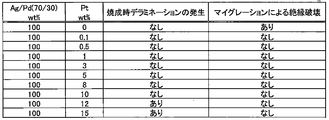
- Example 2 The piezoelectric element for the piezoelectric actuator described above was fabricated by changing the components of the internal electrode and the external electrode, and the piezoelectric actuator 190 for the positioner was assembled. Then, a continuous drive test at 150 VDC for 1000 hours at 180 ° C. was performed. 3 to 5 show the components of each electrode based on Ag / Pd (70/30), Ag / Pd (85/15), and Ag / Pd (60/40), respectively, and the results of 1000-hour continuous driving test. It is a table
- a piezoelectric element having a base material composed of Ag / Pd with a weight ratio of 60/40 to 85/15 and using an electrode containing 0.1 wt% to 10 wt% of Pt with respect to the base material is durable. It was proved to be excellent in performance.
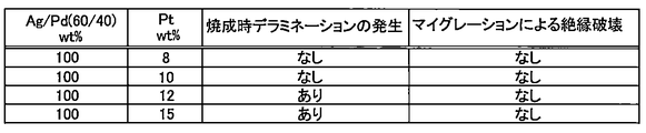
- the piezoelectric elements for the piezoelectric actuator described above were produced by slightly changing the components within the range of the electrode components having excellent durability in the above test, and a continuous driving test by 150 V rectangular wave driving was performed.
- 6 to 8 show the components of each electrode based on Ag / Pd (70/30), Ag / Pd (85/15), and Ag / Pd (60/40), respectively, and 100 million continuous driving tests. It is a table
Landscapes
- Engineering & Computer Science (AREA)
- Power Engineering (AREA)
- Manufacturing & Machinery (AREA)
- Chemical & Material Sciences (AREA)
- Ceramic Engineering (AREA)
- General Electrical Machinery Utilizing Piezoelectricity, Electrostriction Or Magnetostriction (AREA)
- Fuel-Injection Apparatus (AREA)
Abstract
Description
図1(a)、(b)は、圧電素子100を示す斜視図および側断面図である。矩形体に形成された積層型の圧電素子100は、圧電層103と内部電極104、105とが積層方向Zについて交互に積層され、内部電極104、105への電圧の印加により伸縮する。圧電層103は、例えばPZTのような圧電材料で構成され、厚み方向で互い違いの向きに分極されている。
まず、圧電セラミックスのグリーンシートにAg/PdにPtを添加した電極ペーストで内部電極を印刷する、そして、グリーンシートを積層、圧着し、内部電極104、105とともに圧電層103を同時焼成する。得られた焼成体の側面に積層方向に沿って、内部電極104、105に接続するように電極ペーストを印刷して焼き付けることで外部電極106、107を形成できる。このようにして得られた焼成体を分極処理することで、圧電素子100が得られる。
図2は、圧電トランス用の圧電素子200を示す斜視図である。圧電素子200は、矩形体に形成され、入力端子250から1次側に印加された入力電圧を変換(昇圧または降圧)し、変換された電圧を2次側の出力端子260へ出力する。
まず、圧電セラミックスのグリーンシートにAg/Ptの電極ペーストで内部電極を印刷して積層後、矩形体に加工する。そして入力部および出力部の設計に応じて、入力電力を設け、出力側の端部には端面電極を設ける。このようにして素子の外側面の所定箇所にスクリーン印刷で電極ペーストを塗布し、焼き付けて外部電極を形成する。そして、得られた焼成体を分極処理し、外部電極224、225、232にはリード線を半田付けする。
内部電極および外部電極の成分を変えて、上記の圧電アクチュエータ用の圧電素子を作製しポジショナ用の圧電アクチュエータ190を組み立てその後、180℃で1000時間の150VDCでの連続駆動試験を行った。図3~5は、それぞれAg/Pd(70/30)、Ag/Pd(85/15)、Ag/Pd(60/40)を母材とする各電極の成分および1000時間の連続駆動試験結果を示す表である。なお、括弧内は重量比を表す(以下、同様)。
103 圧電層
104、105 内部電極
106、107 外部電極
110 圧電アクチュエータ本体
121、122 リード部材
130 チップ
140 座
151、152 端子
160 キャップ
190 圧電アクチュエータ
200 圧電素子
220 入力部
221 圧電体層
222、223 内部電極
224、225、232 外部電極
230 出力部
231 圧電体層
250 入力端子
260 出力端子
270 グランド
Claims (5)
- 電圧の印加により伸縮する積層型の圧電素子であって、
素子本体の表面に設けられた外部電極と、
前記外部電極に接続された内部電極と、
前記内部電極と交互に積層された圧電層と、を備え、
前記内部電極または外部電極に用いられる電極材料は、AgとPdとが重量比で60/40~85/15で構成される母材を有し、前記母材に対し0.1wt%~10wt%のPtを含有することを特徴とする圧電素子。 - 前記電極材料は、0.5wt%~5.0wt%のPtを含有することを特徴とする請求項1記載の圧電素子。
- 前記内部電極の間隔が、30μm~500μmであることを特徴とする請求項2に記載の圧電素子。
- 請求項1から請求項3のいずれかに記載の圧電素子を直列に連結して形成されたアクチュエータ本体と、
前記連結された圧電素子を電気的に接続するリード部材と、を備えることを特徴とする圧電アクチュエータ。 - 1次側から入力された電圧を昇圧または降圧して2次側から出力する請求項1から請求項3のいずれかに記載の圧電素子を備えることを特徴とする圧電トランス。
Priority Applications (4)
| Application Number | Priority Date | Filing Date | Title |
|---|---|---|---|
| KR1020187009998A KR20180052689A (ko) | 2015-10-09 | 2016-10-07 | 압전 소자, 압전 액추에이터 및 압전 트랜스 |
| JP2017508702A JP6300255B2 (ja) | 2015-10-09 | 2016-10-07 | 圧電素子、圧電アクチュエータおよび圧電トランス |
| US15/766,907 US10978635B2 (en) | 2015-10-09 | 2016-10-07 | Piezoelectric element, piezoelectric actuator and piezoelectric transformer |
| CN201680058982.7A CN108140720A (zh) | 2015-10-09 | 2016-10-07 | 压电元件、压电驱动器和压电变压器 |
Applications Claiming Priority (2)
| Application Number | Priority Date | Filing Date | Title |
|---|---|---|---|
| JP2015201334 | 2015-10-09 | ||
| JP2015-201334 | 2015-10-09 |
Publications (1)
| Publication Number | Publication Date |
|---|---|
| WO2017061592A1 true WO2017061592A1 (ja) | 2017-04-13 |
Family
ID=58487917
Family Applications (1)
| Application Number | Title | Priority Date | Filing Date |
|---|---|---|---|
| PCT/JP2016/079923 Ceased WO2017061592A1 (ja) | 2015-10-09 | 2016-10-07 | 圧電素子、圧電アクチュエータおよび圧電トランス |
Country Status (6)
| Country | Link |
|---|---|
| US (1) | US10978635B2 (ja) |
| JP (1) | JP6300255B2 (ja) |
| KR (1) | KR20180052689A (ja) |
| CN (1) | CN108140720A (ja) |
| TW (1) | TWI624969B (ja) |
| WO (1) | WO2017061592A1 (ja) |
Families Citing this family (2)
| Publication number | Priority date | Publication date | Assignee | Title |
|---|---|---|---|---|
| CN110890456B (zh) * | 2019-12-05 | 2022-07-19 | 湖南嘉业达电子有限公司 | 一种可抑制银迁移的微孔雾化元件及其制备方法 |
| TWI866221B (zh) * | 2023-05-19 | 2024-12-11 | 正修學校財團法人正修科技大學 | 雙晶片型壓電變壓器 |
Citations (6)
| Publication number | Priority date | Publication date | Assignee | Title |
|---|---|---|---|---|
| JP2003124535A (ja) * | 2001-10-11 | 2003-04-25 | Toyota Motor Corp | 圧電素子および圧電素子の表面処理方法 |
| JP2004071905A (ja) * | 2002-08-07 | 2004-03-04 | Murata Mfg Co Ltd | 積層型圧電セラミック素子の製造方法 |
| JP2005150369A (ja) * | 2003-11-14 | 2005-06-09 | Kyocera Corp | 積層型圧電素子およびこれを用いた噴射装置 |
| JP2014231642A (ja) * | 2007-09-07 | 2014-12-11 | イー・アイ・デュポン・ドウ・ヌムール・アンド・カンパニーE.I.Du Pont De Nemours And Company | 銀および少なくとも2種の非銀含有元素を含有する多元素合金粉末 |
| JP2015122438A (ja) * | 2013-12-24 | 2015-07-02 | 株式会社日本セラテック | 圧電素子、圧電アクチュエータおよび圧電素子の製造方法 |
| JP2015133415A (ja) * | 2014-01-14 | 2015-07-23 | 株式会社日本セラテック | 圧電素子 |
Family Cites Families (20)
| Publication number | Priority date | Publication date | Assignee | Title |
|---|---|---|---|---|
| JPH0543495U (ja) | 1991-11-12 | 1993-06-11 | 日本特殊陶業株式会社 | セラミツクヒータ |
| JP3399785B2 (ja) * | 1997-05-27 | 2003-04-21 | 富士通株式会社 | 圧電体装置及びその製造方法 |
| TW432731B (en) * | 1998-12-01 | 2001-05-01 | Murata Manufacturing Co | Multilayer piezoelectric part |
| DE10006352A1 (de) * | 2000-02-12 | 2001-08-30 | Bosch Gmbh Robert | Piezoelektrischer Keramikkörper mit silberhaltigen Innenelektroden |
| US20030020377A1 (en) * | 2001-07-30 | 2003-01-30 | Ngk Insulators, Ltd. | Piezoelectric/electrostrictive element and piezoelectric/electrostrictive device and production method thereof |
| EP2037511A3 (en) | 2003-09-24 | 2009-04-22 | Kyocera Corporation | Multilayer piezoelectric element |
| EP2012374B1 (en) * | 2003-09-24 | 2012-04-25 | Kyocera Corporation | Multi-layer piezoelectric element |
| JP4593909B2 (ja) | 2003-12-17 | 2010-12-08 | 京セラ株式会社 | 積層型圧電素子および噴射装置 |
| WO2005031887A1 (ja) | 2003-09-25 | 2005-04-07 | Kyocera Corporation | 積層型圧電素子 |
| US20070125977A1 (en) | 2003-11-26 | 2007-06-07 | Tomohiro Kawamoto | Piezoelectric ceramic and laminated piezoelectric element |
| JP4535721B2 (ja) * | 2003-11-26 | 2010-09-01 | 京セラ株式会社 | 圧電磁器および積層型圧電素子並びに噴射装置 |
| JP4925563B2 (ja) * | 2004-03-17 | 2012-04-25 | 京セラ株式会社 | 積層型圧電素子およびこれを用いた噴射装置 |
| WO2007066453A1 (ja) * | 2005-12-08 | 2007-06-14 | Murata Manufacturing Co., Ltd. | 積層型圧電素子およびその製造方法 |
| JP4987848B2 (ja) * | 2006-03-07 | 2012-07-25 | 京セラ株式会社 | セラミック部材の製造方法 |
| US8757130B2 (en) * | 2008-08-28 | 2014-06-24 | Kyocera Corporation | Multi-layer piezoelectric element, injection device, and fuel injection system |
| US20100209287A1 (en) * | 2009-02-18 | 2010-08-19 | Charles Bennett | Tarnish resistant low gold and low palladium yellow jewelry alloys with enhanced castability |
| US20110128665A1 (en) * | 2009-11-30 | 2011-06-02 | Avx Corporation | Ceramic Capacitors for High Temperature Applications |
| JP2014187061A (ja) | 2013-03-21 | 2014-10-02 | Taiheiyo Cement Corp | 圧電素子およびその作製方法 |
| JP5915703B2 (ja) | 2014-02-27 | 2016-05-11 | Tdk株式会社 | 圧電素子ユニットおよび駆動装置 |
| JP2016189372A (ja) * | 2015-03-30 | 2016-11-04 | セイコーエプソン株式会社 | 圧電駆動装置、ロボット及びポンプ |
-
2016
- 2016-10-03 TW TW105131851A patent/TWI624969B/zh not_active IP Right Cessation
- 2016-10-07 JP JP2017508702A patent/JP6300255B2/ja active Active
- 2016-10-07 US US15/766,907 patent/US10978635B2/en active Active
- 2016-10-07 KR KR1020187009998A patent/KR20180052689A/ko not_active Ceased
- 2016-10-07 CN CN201680058982.7A patent/CN108140720A/zh active Pending
- 2016-10-07 WO PCT/JP2016/079923 patent/WO2017061592A1/ja not_active Ceased
Patent Citations (6)
| Publication number | Priority date | Publication date | Assignee | Title |
|---|---|---|---|---|
| JP2003124535A (ja) * | 2001-10-11 | 2003-04-25 | Toyota Motor Corp | 圧電素子および圧電素子の表面処理方法 |
| JP2004071905A (ja) * | 2002-08-07 | 2004-03-04 | Murata Mfg Co Ltd | 積層型圧電セラミック素子の製造方法 |
| JP2005150369A (ja) * | 2003-11-14 | 2005-06-09 | Kyocera Corp | 積層型圧電素子およびこれを用いた噴射装置 |
| JP2014231642A (ja) * | 2007-09-07 | 2014-12-11 | イー・アイ・デュポン・ドウ・ヌムール・アンド・カンパニーE.I.Du Pont De Nemours And Company | 銀および少なくとも2種の非銀含有元素を含有する多元素合金粉末 |
| JP2015122438A (ja) * | 2013-12-24 | 2015-07-02 | 株式会社日本セラテック | 圧電素子、圧電アクチュエータおよび圧電素子の製造方法 |
| JP2015133415A (ja) * | 2014-01-14 | 2015-07-23 | 株式会社日本セラテック | 圧電素子 |
Also Published As
| Publication number | Publication date |
|---|---|
| KR20180052689A (ko) | 2018-05-18 |
| JP6300255B2 (ja) | 2018-03-28 |
| TW201717439A (zh) | 2017-05-16 |
| US10978635B2 (en) | 2021-04-13 |
| TWI624969B (zh) | 2018-05-21 |
| JPWO2017061592A1 (ja) | 2017-10-05 |
| US20180301617A1 (en) | 2018-10-18 |
| CN108140720A (zh) | 2018-06-08 |
Similar Documents
| Publication | Publication Date | Title |
|---|---|---|
| JP6300255B2 (ja) | 圧電素子、圧電アクチュエータおよび圧電トランス | |
| JP2005108989A (ja) | 積層型圧電素子とその製造方法 | |
| JP2006203070A (ja) | 積層型圧電素子 | |
| JP2009131138A (ja) | 積層型圧電アクチュエータ素子 | |
| JP2016529721A (ja) | 外部接続部を有する多層デバイス、および外部接続部を有する多層デバイスを製造するための方法 | |
| JP6306698B2 (ja) | 多層デバイスおよび多層デバイスを製造するための方法 | |
| JPH053349A (ja) | 積層型圧電アクチユエータおよびその製造方法 | |
| JP2017188628A (ja) | 圧電素子、その製造方法および圧電アクチュエータ | |
| JP6274393B2 (ja) | 圧電素子 | |
| JP5068936B2 (ja) | 積層型圧電素子の製造方法 | |
| JP5687935B2 (ja) | 圧電アクチュエータ | |
| JP2007019420A (ja) | 積層型圧電素子 | |
| JP4373904B2 (ja) | 積層型圧電素子 | |
| JP2019029405A (ja) | 積層型圧電素子 | |
| JP2014187061A (ja) | 圧電素子およびその作製方法 | |
| JP5205689B2 (ja) | 積層型圧電素子 | |
| JP5859755B2 (ja) | 圧電素子 | |
| JP2007266468A (ja) | 積層型圧電素子 | |
| JP2008192807A (ja) | 積層型圧電アクチュエータ素子及び積層型圧電アクチュエータ | |
| JP6226451B2 (ja) | 圧電素子および圧電アクチュエータ | |
| JP3080033B2 (ja) | 積層型圧電トランス | |
| JP2008288259A (ja) | 積層型圧電アクチュエータ素子及び積層型圧電アクチュエータ | |
| JPH10270768A (ja) | 積層型圧電トランス | |
| JP2006245594A (ja) | 積層型圧電素子の製造方法及び積層型圧電素子 | |
| JP6542618B2 (ja) | 圧電アクチュエータ |
Legal Events
| Date | Code | Title | Description |
|---|---|---|---|
| ENP | Entry into the national phase |
Ref document number: 2017508702 Country of ref document: JP Kind code of ref document: A |
|
| 121 | Ep: the epo has been informed by wipo that ep was designated in this application |
Ref document number: 16853743 Country of ref document: EP Kind code of ref document: A1 |
|
| ENP | Entry into the national phase |
Ref document number: 20187009998 Country of ref document: KR Kind code of ref document: A |
|
| WWE | Wipo information: entry into national phase |
Ref document number: 15766907 Country of ref document: US |
|
| NENP | Non-entry into the national phase |
Ref country code: DE |
|
| 122 | Ep: pct application non-entry in european phase |
Ref document number: 16853743 Country of ref document: EP Kind code of ref document: A1 |