WO2017061110A1 - 顕微鏡装置および結像方法 - Google Patents
顕微鏡装置および結像方法 Download PDFInfo
- Publication number
- WO2017061110A1 WO2017061110A1 PCT/JP2016/004476 JP2016004476W WO2017061110A1 WO 2017061110 A1 WO2017061110 A1 WO 2017061110A1 JP 2016004476 W JP2016004476 W JP 2016004476W WO 2017061110 A1 WO2017061110 A1 WO 2017061110A1
- Authority
- WO
- WIPO (PCT)
- Prior art keywords
- light
- pattern
- display unit
- phase difference
- phase
- Prior art date
Links
Images


Classifications
-
- G—PHYSICS
- G02—OPTICS
- G02B—OPTICAL ELEMENTS, SYSTEMS OR APPARATUS
- G02B21/00—Microscopes
- G02B21/06—Means for illuminating specimens
- G02B21/08—Condensers
- G02B21/14—Condensers affording illumination for phase-contrast observation
-
- G—PHYSICS
- G01—MEASURING; TESTING
- G01N—INVESTIGATING OR ANALYSING MATERIALS BY DETERMINING THEIR CHEMICAL OR PHYSICAL PROPERTIES
- G01N21/00—Investigating or analysing materials by the use of optical means, i.e. using sub-millimetre waves, infrared, visible or ultraviolet light
- G01N21/17—Systems in which incident light is modified in accordance with the properties of the material investigated
- G01N21/25—Colour; Spectral properties, i.e. comparison of effect of material on the light at two or more different wavelengths or wavelength bands
- G01N21/255—Details, e.g. use of specially adapted sources, lighting or optical systems
-
- G—PHYSICS
- G01—MEASURING; TESTING
- G01N—INVESTIGATING OR ANALYSING MATERIALS BY DETERMINING THEIR CHEMICAL OR PHYSICAL PROPERTIES
- G01N21/00—Investigating or analysing materials by the use of optical means, i.e. using sub-millimetre waves, infrared, visible or ultraviolet light
- G01N21/17—Systems in which incident light is modified in accordance with the properties of the material investigated
- G01N21/25—Colour; Spectral properties, i.e. comparison of effect of material on the light at two or more different wavelengths or wavelength bands
- G01N21/27—Colour; Spectral properties, i.e. comparison of effect of material on the light at two or more different wavelengths or wavelength bands using photo-electric detection ; circuits for computing concentration
-
- G—PHYSICS
- G02—OPTICS
- G02B—OPTICAL ELEMENTS, SYSTEMS OR APPARATUS
- G02B21/00—Microscopes
- G02B21/06—Means for illuminating specimens
- G02B21/08—Condensers
- G02B21/086—Condensers for transillumination only
-
- G—PHYSICS
- G02—OPTICS
- G02B—OPTICAL ELEMENTS, SYSTEMS OR APPARATUS
- G02B21/00—Microscopes
- G02B21/34—Microscope slides, e.g. mounting specimens on microscope slides
-
- G—PHYSICS
- G02—OPTICS
- G02B—OPTICAL ELEMENTS, SYSTEMS OR APPARATUS
- G02B21/00—Microscopes
- G02B21/36—Microscopes arranged for photographic purposes or projection purposes or digital imaging or video purposes including associated control and data processing arrangements
- G02B21/361—Optical details, e.g. image relay to the camera or image sensor
-
- G—PHYSICS
- G02—OPTICS
- G02B—OPTICAL ELEMENTS, SYSTEMS OR APPARATUS
- G02B27/00—Optical systems or apparatus not provided for by any of the groups G02B1/00 - G02B26/00, G02B30/00
- G02B27/50—Optics for phase object visualisation
- G02B27/52—Phase contrast optics
Definitions
- the present invention relates to a microscope apparatus that captures a phase difference image by irradiating an observation target with illumination light for phase difference measurement.
- phase difference measurement has been widely used as a method for observing cultured cultured cells such as stem cells without staining.
- a phase contrast microscope is used to perform such phase difference measurement.
- phase contrast microscope In a general phase contrast microscope, ring-shaped illumination light is irradiated onto an observation target, and direct light that has passed through the observation target and diffracted light diffracted by the observation target are incident on the phase plate.
- the direct light is attenuated and shifted in phase by the ring portion of the phase plate, and the diffracted light passes through the transparent portion of the phase plate.
- a phase difference image with contrast can be captured.
- JP 2012-222672 A JP 2008-139613 A Japanese Patent Laying-Open No. 2015-082100
- phase contrast image captured by the phase contrast microscope can emphasize contrast such as the outline of the cell, but the color of the cell may not appear clearly.
- an undifferentiated state of iPS cells may be confirmed by adding alkaline phosphatase, which is a pluripotent marker, to iPS (induced pluripotent cells) cells and observing the color thereof.
- alkaline phosphatase which is a pluripotent marker
- phase contrast microscopes cannot capture images that can clearly observe the contrast of cell outlines while observing changes in cell color. could not be imaged.
- Patent Document 1 and Patent Document 2 disclose a microscope that can capture a phase difference image and also a bright field image. However, an image with clear color and contrast can be obtained. It cannot be imaged.
- Patent Document 3 discloses a microscope that performs oblique illumination observation, but even with this microscope, it is not possible to capture an image with clear color and contrast.
- an object of the present invention is to provide a microscope apparatus and an imaging method capable of capturing an image with clear color and contrast of an observation target such as a cell.
- the microscope apparatus of the present invention includes an illumination light irradiating unit that irradiates an observation target with illumination light for phase difference measurement, a transmissive display unit on which light transmitted through the observation target by irradiation with illumination light for phase difference measurement is incident, An imaging unit that images the observation target by detecting light transmitted through the transmission display unit, and the transmission display unit has different transmission densities for each of the light beams having a plurality of wavelengths included in the light transmitted through the observation target. A pattern is displayed.
- the light of a plurality of wavelengths means a plurality of lights having different spectral spectra.
- the transmission type display unit can display the patterns for each light having a plurality of wavelengths at different positions.
- the transmission type display unit can display a pattern for each light having a plurality of wavelengths concentrically.
- the transmissive display unit can display a pattern in which the transmission density for light having a relatively short wavelength is higher than the transmission density for light having a relatively long wavelength.
- the transmission type display unit can display a pattern in which the transmission density for blue light is higher than the transmission density for red light and green light.
- a wavelength selection receiving unit that receives selection of light having a wavelength that relatively increases the transmission density can be further provided, and the transmission type display unit is received by the wavelength selection receiving unit.
- the transmission density of the light of each wavelength of the pattern can be changed according to the light of the different wavelength.
- red light, green light and blue light can be used as light of a plurality of wavelengths.
- the transmission type display unit can switch between a phase difference observation mode for displaying the pattern and a bright field observation mode for not displaying the pattern.
- the transmission type display unit can display a pattern that blocks light of all wavelengths included in the illumination light for phase difference measurement in the phase difference observation mode.
- the pattern is preferably a ring-shaped pattern.
- the microscope apparatus of the present invention may further include a phase changing unit that receives light transmitted through the observation target by irradiation of phase difference measurement illumination light and shifts the phase of the incident light.
- the imaging method of the present invention irradiates the observation target with illumination light for phase difference measurement, causes the light transmitted through the observation target by irradiation with the illumination light for phase difference measurement to enter the transmissive display unit, and transmits the observation target.
- Displaying a pattern with different transmission densities for light of a plurality of wavelengths included in light on a transmissive display unit, and imaging an observation object by detecting light transmitted through the transmissive display unit on which the pattern is displayed It is characterized by.
- the light transmitted through the observation target by the irradiation of the phase difference measurement illumination light is incident on the transmission type display unit, and is transmitted for each of the light having a plurality of wavelengths included in the light transmitted through the observation target.
- Patterns having different densities are displayed on the transmissive display unit, and light transmitted through the transmissive display unit on which the pattern is displayed is detected.
- the direct light is attenuated by the above pattern, so that an effect equivalent to the dimming effect in phase difference observation can be obtained.
- the imaging method of the present invention can also obtain the same effects as the microscope apparatus of the present invention.
- the figure which shows an example of a structure of a slit board The figure which shows an example of the red adjustment pattern, green adjustment pattern, and blue adjustment pattern which are displayed on a transmissive display part Diagram showing an example of the configuration of a phase plate
- the figure which shows an example of the pattern displayed on a transmissive display part The figure which shows an example of the pattern displayed on a transmissive display part
- the figure which shows an example of the pattern displayed on a transmissive display part The figure which shows an example of the pattern displayed on a transmissive display part
- the figure which shows an example of the pattern displayed on a transmissive display part The figure which shows an example of the pattern displayed on a transmissive display part
- the figure which shows an example of the pattern displayed on a transmissive display part The flowchart for demonstrating the effect
- FIG. 1 is a diagram showing a schematic configuration of the microscope system of the present embodiment.
- the microscope system of the present embodiment includes an illumination light irradiation unit 10, an imaging optical system 20, an imaging unit 30, a microscope control device 40, a display device 50, and an input device 55. ing.
- a stage 61 is provided between the illumination light irradiation unit 10 and the imaging optical system 20, and a culture vessel 60 in which the observation target S is accommodated is installed on the stage 61.
- the stage 61 is moved in the X and Y directions orthogonal to each other by the stage driving unit 62.
- the X direction and the Y direction are directions orthogonal to each other on a plane parallel to the installation surface of the observation target S of the culture vessel 60.
- a phase contrast microscope apparatus is configured by the illumination light irradiation unit 10, the imaging optical system 20, the imaging unit 30, the stage 61, and the stage driving unit 62, and the microscope control device 40 includes the phase difference. It controls the microscope apparatus.
- the microscope control device 40 includes the phase difference. It controls the microscope apparatus.
- the illumination light irradiation unit 10 irradiates the observation target S accommodated in the culture vessel 60 with illumination light for so-called phase difference measurement.
- the illumination light for phase difference measurement is provided.
- the illumination light irradiation unit 10 of the present embodiment includes a white light source 11 that emits white light and a ring-shaped slit, and the white light emitted from the white light source 11 is incident on the ring light.
- a slit plate 12 that emits light
- a first objective lens 13 that receives the ring-shaped illumination light emitted from the slit plate 12 and irradiates the incident ring-shaped illumination light onto the observation object S. ing.
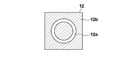
- FIG. 2 is a diagram showing a specific configuration of the slit plate 12.
- the slit plate 12 is provided with a ring-shaped slit 12 a that transmits white light to a light blocking plate 12 b that blocks white light emitted from the white light source 11. Ring-shaped illumination light is formed by passing through the slit 12a.
- the ring-shaped illumination light is formed using the slit plate 12 as described above.
- the method for forming the ring-shaped illumination light is not limited to this, for example, spatial light modulation.
- Ring-shaped illumination light may be formed using an element or the like.
- the ring-shaped illumination light is used as the phase difference measurement illumination light.
- illumination light having a structure other than the ring shape may be used, and it may have a shape conjugate with a phase plate described later.
- other shapes such as a triangular shape and a rectangular shape may be used.
- the culture vessel 60 installed on the stage 61 is formed of a resin or glass transparent to white light, and for example, a petri dish, a dish, a well plate, or the like can be used. And a cell group etc. are arrange
- FIG. Cell groups to be observed include pluripotent stem cells such as iPS cells and ES (embryonic cells), nerves, skin, myocardium and liver cells derived from stem cells, and skin, retina and myocardium extracted from the human body. , Blood cells, nerves and organ cells.
- a culture solution C for culturing a cell group is also accommodated.
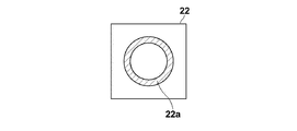
- the imaging optical system 20 includes a second objective lens 21, a transmissive display unit 22, a phase plate 23, and an imaging lens 24.
- the second objective lens 21 is moved in the Z direction by a lens driving unit (not shown).
- the autofocus control is performed by the movement of the second objective lens 21 in the Z direction, and the contrast of the image captured by the imaging unit 30 is adjusted.
- the transmissive display unit 22 transmits the observation target S and receives the light collected by the second objective lens 21. Specifically, the transmissive display unit 22 transmits white light and can perform color display. A transparent liquid crystal display. The transmissive display unit 22 displays a pattern having different transmission densities for each of light having a plurality of wavelengths included in the light transmitted through the observation target S. In the present embodiment, a transmissive liquid crystal display is used as the transmissive display unit 22, but other transmissive displays such as a transmissive organic EL display may be used.
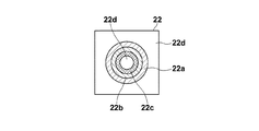
- the transmissive display unit 22 of the present embodiment includes a red adjustment pattern 22a for adjusting the red light transmission density and a green adjustment pattern 22b for adjusting the green light transmission density.
- the blue adjustment pattern 22c for adjusting the blue light transmission density is displayed. It should be noted that nothing is displayed in the range 22d other than the red adjustment pattern 22a, the green adjustment pattern 22b, and the blue adjustment pattern 22c, and is transparent to light of all wavelengths included in the light transmitted through the observation target S.
- the red adjustment pattern 22a is a pattern for adjusting the transmission density of red light out of the light transmitted through the observation target S, and is displayed in a color that absorbs red light. Specifically, for example, it is a green or blue-green pattern that absorbs red.
- the green adjustment pattern 22b is a pattern for adjusting the transmission density of green light out of the light transmitted through the observation target S, and is displayed in a color that absorbs green light. Specifically, it is a red or magenta pattern that absorbs green, for example.
- the blue adjustment pattern 22c is a pattern for adjusting the transmission density of blue light out of the light transmitted through the observation target S, and is displayed in a color that absorbs blue light. Specifically, for example, it is a yellow pattern that absorbs blue.
- the red adjustment pattern 22a, the green adjustment pattern 22b, and the blue adjustment pattern 22c are displayed concentrically as shown in FIG. 3, and the red adjustment pattern 22a is displayed on the outermost side and the blue adjustment pattern 22c is displayed on the innermost side.
- the green adjustment pattern 22b is displayed between the red adjustment pattern 22a and the blue adjustment pattern 22c.
- the transmissive display unit 22 is disposed at a position optically conjugate with the slit plate 12 described above, and the red adjustment pattern 22a, the green adjustment pattern 22b, and the blue adjustment pattern 22c have the same shape as the slit 12a of the slit plate 12. It is a combination.
- the red adjustment pattern 22a, the green adjustment pattern 22b, and the blue adjustment pattern 22c are displayed in the arrangement as described above.
- the direct light transmitted through the observation target S includes red light, green light, and blue light.
- the manner of refraction differs depending on the wavelength, and the irradiation positions of the red light, the green light, and the blue light on the transmission display unit 22 are different.
- the transmission density of each color can be adjusted more appropriately.
- FIG. 4 is a plan view showing a specific configuration of the phase plate 23.
- the phase plate 23 is formed from a member that is transparent to the wavelength of the ring-shaped illumination light, and includes a phase ring 23a.
- the phase ring 23a is a ring in which a phase film that shifts the phase of incident light by a quarter wavelength is formed.
- the direct light incident on the phase plate 23 passes through the phase ring 23a, so that the phase is shifted by 1 ⁇ 4 wavelength.
- most of the diffracted light diffracted by the observation object S passes through a portion other than the phase ring 23a of the phase plate 23, and its phase does not change.
- the phase ring 23a is formed in a range corresponding to the display range of the red adjustment pattern 22a, the green adjustment pattern 22b, and the blue adjustment pattern 22c, and is transparent to the wavelength of the ring-shaped illumination light.
- phase difference image of the observation object S can be obtained by the action of light absorption by the pattern displayed on the transmission type display unit 22 and light phase shift by the phase plate 23.
- general phase difference observation The operation of will be described.
- the phase of the direct light and the diffracted light can be aligned or shifted by a half wavelength. Can be emphasized more.
- the contrast between the imaging light caused by the interference between the direct light and the diffracted light and the imaging light of the direct light can be enhanced. Thereby, a phase difference image in which the structure of the observation target is emphasized can be formed.
- the light of all wavelength components (colors) included in the direct light is dimmed for the color to be observed, so it is difficult to understand the color change of the phase contrast image. There is a case.
- the direct light of the red component of the light transmitted through the observation target S is attenuated by the red adjustment pattern 22a and the phase thereof is changed by the phase ring 23a. It is shifted by a quarter wavelength.
- the diffracted light of the red component passes through parts other than the red adjustment pattern 22a and the phase ring 23a, and its intensity and phase do not change. Therefore, the intensity of the imaging light due to the interference between the direct light of the red component and the diffracted light can be increased, and the contrast between the imaging light and the direct light can be increased. A phase difference image can be formed.
- the direct light of the green component and the blue component of the light transmitted through the observation object S is not attenuated by the red adjustment pattern 22a.
- the contrast is not increased, but the same intensity as bright field observation can be obtained.
- a bright-field image having a green component and a blue component as main components, that is, a water color component as a main component can be formed.
- the light transmitted through the observation object S passes through the transmissive display unit 22 and the phase plate 23, so that both the phase difference image mainly composed of the red component and the bright field image mainly composed of the chromatic component are formed.
- An image having the following characteristics can be formed. Therefore, it is possible to form an image with clear color and contrast of an observation target such as a cell.
- phase plate 23 of the present embodiment corresponds to the phase changing unit of the present invention.
- the configuration of the phase changing unit is not limited to the above configuration, and the phase plate 23 may be switched according to the color of the adjustment pattern displayed on the transmissive display unit 22.
- a phase plate having a phase ring that selectively shifts the phase of the red light by 1 ⁇ 4 wavelength is used.
- the green adjustment pattern 22b is displayed, a phase plate having a phase ring that selectively shifts the phase of the green light by 1 ⁇ 4 wavelength is used, and when the blue adjustment pattern 22c is displayed on the transmissive display unit 22. May use a phase plate having a phase ring that shifts the phase of blue light by 1 ⁇ 4 wavelength.
- a transmissive spatial light modulation element for changing the phase may be used instead of the phase plate 23, a transmissive spatial light modulation element for changing the phase may be used.
- the transmissive spatial light modulator may be controlled so that the phase is shifted by a quarter wavelength for all wavelengths of incident light, or the phase is set to 1 according to the display pattern of the transmissive display unit 22.
- the transmissive spatial light modulator may be controlled so as to select the wavelength of the light shifted by / 4 wavelength.
- the phase plate 23 is provided.
- the phase plate 23 is not necessarily provided. Even in this case, the phase difference image in which the contrast is enhanced by the light attenuation by the transmissive display unit 22. Can be obtained.
- the phase plate 23 may be provided.
- the transmissive display unit 22 displays the adjustment pattern described above and the phase of incident light. It can also be shifted by a quarter wavelength.
- the transmissive display unit 22 switches the pattern display according to the type of image desired by the user.
- red adjustment pattern 22a and the blue adjustment pattern 22c are displayed without displaying the green adjustment pattern 22b
- red light and blue light of the light transmitted through the observation target S are displayed. Since the direct light is absorbed and dimmed and the direct light of green light is transmitted, the image has the contrast of the phase contrast image of purple light combining red light and blue light and the color characteristics of bright field image of green light Is obtained.
- red adjustment pattern 22a and the green adjustment pattern 22b are displayed without displaying the blue adjustment pattern 22c
- red light and green light of the light transmitted through the observation target S are displayed. Since the direct light is absorbed and dimmed and the direct light of blue light is transmitted, the image has the contrast of the phase difference image of yellow light combining red light and green light and the color characteristics of bright field image of blue light Is obtained.
- the direct light of the green light out of the light transmitted through the observation target S is displayed. Is absorbed and dimmed, and the direct light of red light and blue light is transmitted, so that an image having the contrast of the phase difference image of green light and the color characteristics of a bright field image of violet light is obtained.
- the imaging lens 24 receives direct light and diffracted light that have passed through the transmissive display unit 22 and the phase plate 23, and forms an image of these lights on the imaging unit 30.
- the imaging unit 30 includes an imaging element that captures an image formed by the imaging lens 24.
- a charge-coupled device (CCD) image sensor, a complementary metal-oxide semiconductor (CMOS) image sensor, or the like is used as the imaging device.
- CMOS complementary metal-oxide semiconductor
- red, green, and blue filters are used as the image sensor.
- An image sensor having a color filter made of is used.
- the microscope control device 40 is composed of a computer equipped with a CPU (Central Processing Unit) and a storage device.
- a CPU Central Processing Unit
- the microscope control device 40 controls the display of each pattern of the transmissive display unit 22 to control the transmission density of light of each color, and a transmission density control unit 41. And a stage control unit 42 for controlling the stage driving unit 62.
- the transmission density control unit 41 receives information on the type of desired phase difference image set and input by the user using the input device 55, and controls display of each pattern on the transmission type display unit 22 based on the information. It is. Specifically, for example, the user uses the input device 55 to input a color setting that is a base of the phase difference image.
- the color that is the base of the phase difference image is a color that relatively increases the transmission density in the transmissive display unit 22. For example, when it is desired to set the base color of the phase difference image to red, the information is set and input by the user.
- the transmission density control unit 41 controls the transmission type display unit 22 so that the red transmission density is relatively high based on the color information set and input by the user.
- control is performed so that only the red adjustment pattern 22a is displayed without displaying the green adjustment pattern 22b and the blue adjustment pattern 22c.
- the transmission density control unit 41 controls the display of each pattern on the transmissive display unit 22 in accordance with the color information that is the base of the phase difference image set and input by the user.
- the microscope control device 40 controls the drive of the image pickup device of the image pickup unit 30, acquires an image signal output from the image pickup device, and causes the display device 50 to display an image based on the image signal.
- the input device 55 and a display device 50 are connected to the microscope control device 40.
- the input device 55 includes input devices such as a keyboard and a mouse, and accepts setting input by the user.
- the input device 55 according to the present embodiment receives a setting input of color information for relatively increasing the transmission density in the transmissive display unit 22 as described above.
- the input device 55 corresponds to the wavelength selection receiving unit of the present invention.
- the display device 50 is configured by a display device such as a liquid crystal display, and displays an image captured by the imaging unit 30. Note that the display device 50 and the input device 55 may be configured by a touch panel.
- the culture container 60 containing the observation object S and the culture medium C is placed on the stage 61 (S10).
- the user uses the input device 55 to select and input a color that is the base of the phase difference image (S12).
- the color information that is the base of the phase difference image set and input by the user is input to the transmission density control unit 41, and the transmission density control unit 41 inputs each color to the transmission type display unit 22 based on the input color information.
- the adjustment pattern is displayed (S14).
- the ring-shaped illumination light is emitted from the illumination light irradiation unit 10 and irradiated to the observation target S of the culture vessel 60 (S16).
- the light transmitted through the observation object S is collected by the second objective lens 21 and is incident on the transmissive display unit 22 and the phase plate 23.
- a phase difference image of the observation object S is formed by the color of the adjustment pattern displayed on the transmissive display unit 22 and the action of the phase plate 23, and a bright field image of a color other than the wavelength forming the phase difference image is formed. It is formed. Then, these images are imaged on the imaging unit 30 by the imaging lens 24, whereby an image of the observation target S having the contrast of the phase difference image and the color characteristic of the bright field image is captured by the imaging unit 30 ( S18).
- the image signal captured by the imaging unit 30 is output to the microscope control device 40, and the microscope control device 40 causes the display device 50 to display an image of the observation target S based on the input image signal (S20).
- the light transmitted through the observation target S by the irradiation of the phase difference measurement illumination light is incident on the transmissive display unit 22, and has a plurality of wavelengths included in the light transmitted through the observation target S.
- a pattern having a different transmission density for each light is displayed on the transmissive display unit 22, and the observation target S is imaged by detecting light transmitted through the transmissive display unit 22 on which the pattern is displayed.
- light with a wavelength having a relatively high transmission density is attenuated by the above pattern, so that the same effect as phase difference observation can be obtained. Since the pattern is not dimmed, the same effect as bright field observation can be obtained. That is, by detecting the light transmitted through the transmissive display unit 22, it is possible to capture an image with clear color and contrast of the observation target S.
- various patterns as shown in FIGS. 5I to 5VI can be displayed on the transmissive display unit 22, but not all of these patterns may be displayed. You may make it fix to the display of such a pattern. In that case, it is desirable to display a pattern in which the transmission density for light having a relatively short wavelength is higher than the transmission density for light having a relatively long wavelength. Since light having a shorter wavelength has a smaller diffraction angle and a clearer contrast, it is desirable to increase the transmission density of this light and increase the contribution to the phase difference image.
- the user sets and inputs the color information that is the base of the phase difference image.
- the present invention is not limited to this, and the type information of the observation object S and the transmission type display unit 22 are displayed.
- a pattern that is associated with the pattern type information is set in advance in the transmission density control unit 41, and is displayed on the transmission type display unit 22 based on the information on the type of the observation target S set and input by the user. May be controlled.
- Information on the type of observation object S includes information on the type of cells, information on the type of reagent such as alkaline phosphatase, and the like.
- the size of each color pattern displayed on the transmission type display unit 22 is changed according to the cell type information. May be. Specifically, the diameter of the pattern of each color may be increased in the case of a cell having a larger scattering.
- the red adjustment pattern 22a, the green adjustment pattern 22b, and the blue adjustment pattern 22c are displayed concentrically at different positions. These patterns may be switched and displayed based on the color information set and input by.
- the user can input the setting of the phase difference observation mode and the bright field observation mode.
- the transmission density control unit 41 displays the transmission type display unit. No image is displayed on 22, and the bright field image of the observation target S may be captured by the imaging unit 30.
- the red adjustment pattern 22a, the green adjustment pattern 22b, and the blue adjustment pattern 22c are displayed on the transmissive display unit 22. That is, RGB (Red, Green, Blue) light is absorbed.
- RGB Red, Green, Blue
- the pattern is displayed, a pattern that absorbs cyan, magenta, and yellow light may be displayed. In that case, a complementary color image sensor having cyan, magenta, and yellow color filters may be used as the image sensor.
- the observation target is irradiated with the illumination light for phase difference measurement made of white light.
- the present invention is not limited to this.
- the observation target such as a cell is made of excitation light. It is also possible to irradiate phase difference measurement illumination light and detect fluorescence emitted from cells, fluorescence emitted from reagents, and the like to capture a fluorescence image of an observation target.
Landscapes
- Physics & Mathematics (AREA)
- General Physics & Mathematics (AREA)
- Chemical & Material Sciences (AREA)
- Analytical Chemistry (AREA)
- Optics & Photonics (AREA)
- Engineering & Computer Science (AREA)
- Biochemistry (AREA)
- Spectroscopy & Molecular Physics (AREA)
- Health & Medical Sciences (AREA)
- Life Sciences & Earth Sciences (AREA)
- General Health & Medical Sciences (AREA)
- Immunology (AREA)
- Pathology (AREA)
- Mathematical Physics (AREA)
- Theoretical Computer Science (AREA)
- Multimedia (AREA)
- Microscoopes, Condenser (AREA)
- Investigating Or Analysing Materials By Optical Means (AREA)
Abstract
【課題】細胞などの観察対象の色とコントラストの両方が明瞭な画像を撮像することができる顕微鏡装置および結像方法を提供する。 【解決手段】観察対象に位相差計測用照明光を照射する照明光照射部(10)と、位相差計測用照明光の照射によって観察対象を透過した光が入射される透過型表示部(22)と、透過型表示部(22)を透過した光を検出することによって観察対象を撮像する撮像部(30)とを備え、透過型表示部(22)が、観察対象を透過した光に含まれる複数の波長の光毎に透過濃度が異なるパターンを表示する。
Description
本発明は、観察対象に位相差計測用照明光を照射して位相差画像を撮像する顕微鏡装置に関するものである。
近年、幹細胞などの培養された透明な細胞を非染色に観察する方法として位相差計測が広く使われ始めている。そして、このような位相差計測を行うものとして位相差顕微鏡が使用されている。
一般的な位相差顕微鏡においては、リング状の照明光が観察対象に照射され、観察対象を通過した直接光と観察対象で回折した回折光が位相板に入射される。そして、直接光は位相板のリング部分によって減光されるとともに位相がずらされ、回折光は位相板の透明な部分を通過し、この直接光と回折光とが結像されることによって明暗のコントラストのついた位相差画像を撮像することができる。
ここで、位相差顕微鏡によって撮像された位相差画像は、細胞の輪郭などのコントラストを強調することはできるが、細胞の色については明瞭に現れない場合がある。
たとえばiPS(induced pluripotent stem)細胞に対して多能性マーカであるアルカリホスファターゼを添加し、その色を観察することによってiPS細胞の未分化状態を確認する場合がある。このような場合、位相差顕微鏡によって撮像された位相差画像だけではその色の変化が分かり難い場合がある。
すなわち、従来の位相差顕微鏡では、細胞の色の変化を観察しながら、かつ細胞の輪郭のコントラストを明確に観察できる画像を撮像することができず、その他の明視野顕微鏡などでもこのような画像を撮像することができなかった。
なお、特許文献1および特許文献2には、位相差画像を撮像することができ、かつ明視野画像も撮像することができる顕微鏡が開示されているが、色とコントラストの両方が明瞭な画像を撮像することはできない。
また、特許文献3には、偏斜照明観察を行う顕微鏡が開示されているが、この顕微鏡でも色とコントラストの両方が明瞭な画像を撮像することはできない。
本発明は、上記の問題に鑑み、細胞などの観察対象の色とコントラストの両方が明瞭な画像を撮像することができる顕微鏡装置および結像方法を提供することを目的とする。
本発明の顕微鏡装置は、観察対象に位相差計測用照明光を照射する照明光照射部と、位相差計測用照明光の照射によって観察対象を透過した光が入射される透過型表示部と、透過型表示部を透過した光を検出することによって観察対象を撮像する撮像部とを備え、透過型表示部が、観察対象を透過した光に含まれる複数の波長の光毎に透過濃度が異なるパターンを表示することを特徴とする。
ここで、複数の波長の光とは、異なる分光スペクトルを有する複数の光を意味する。
また、上記本発明の顕微鏡装置において、透過型表示部は、複数の波長の光毎のパターンをそれぞれ異なる位置に表示することができる。
また、上記本発明の顕微鏡装置において、透過型表示部は、複数の波長の光毎のパターンを同心円状に表示することができる。
また、上記本発明の顕微鏡装置において、透過型表示部は、相対的に波長が短い光に対する透過濃度の方が、相対的に波長が長い光に対する透過濃度よりも高いパターンを表示することができる。
また、上記本発明の顕微鏡装置において、透過型表示部は、青色光に対する透過濃度の方が赤色光および緑色光に対する透過濃度よりも高いパターンを表示することができる。
また、上記本発明の顕微鏡装置においては、相対的に透過濃度を高くする波長の光の選択を受け付ける波長選択受付部をさらに設けることができ、透過型表示部は、波長選択受付部によって受け付けられた波長の光に応じて、上記パターンの各波長の光の透過濃度を変更することができる。
また、上記本発明の顕微鏡装置において、複数の波長の光として、赤色光、緑色光および青色光を用いることができる。
また、上記本発明の顕微鏡装置において、透過型表示部は、上記パターンを表示する位相差観察モードと上記パターンを非表示とする明視野観察モードとを切り替え可能とできる。
また、上記本発明の顕微鏡装置において、透過型表示部は、位相差観察モードの場合において、位相差計測用照明光に含まれる全ての波長の光を遮光するパターンを表示することができる。
また、上記本発明の顕微鏡装置において、パターンは、リング状のパターンとすることが好ましい。
また、上記本発明の顕微鏡装置においては、位相差計測用照明光の照射によって観察対象を透過した光が入射され、その入射された光の位相をずらす位相変更部をさらに備えることができる。
本発明の結像方法は、観察対象に位相差計測用照明光を照射し、位相差計測用照明光の照射によって観察対象を透過した光を透過型表示部に入射させ、観察対象を透過した光に含まれる複数の波長の光毎に透過濃度が異なるパターンを透過型表示部に表示させ、上記パターンが表示された透過型表示部を透過した光を検出することによって観察対象を撮像することを特徴とする。
本発明の顕微鏡装置によれば、位相差計測用照明光の照射によって観察対象を透過した光を透過型表示部に入射させ、観察対象を透過した光に含まれる複数の波長の光毎に透過濃度が異なるパターンを透過型表示部に表示させ、上記パターンが表示された透過型表示部を透過した光を検出する。これにより、相対的に透過濃度が高い波長の光については、その直接光が上記パターンによって減光されるので、位相差観察における減光作用と同等の作用を得ることができる。すなわち、上記波長の光の直接光と回折光との干渉による結像光と直接光とのコントラストが強調された位相差画像を取得することができる。一方、相対的に透過濃度が低い波長の光については、上記パターンによって減光されないので一般的な明視野観察と同等の作用を得ることができ、上記波長の光を主成分とする明視野画像を取得することができる。
すなわち、透過型表示部を透過した光を検出することによって、位相差画像と明視野画像の両方の特性を有する画像を撮像することができ、細胞などの観察対象の色とコントラストの両方が明瞭な画像を撮像することができる。
なお、本発明の結像方法も、本発明の顕微鏡装置と同様の効果を得ることができる。
以下、本発明の顕微鏡装置の一実施形態を用いた顕微鏡システムについて、図面を参照しながら詳細に説明する。図1は、本実施形態の顕微鏡システムの概略構成を示す図である。
本実施形態の顕微鏡システムは、図1に示すように、照明光照射部10と、結像光学系20と、撮像部30と、顕微鏡制御装置40と、表示装置50、入力装置55とを備えている。照明光照射部10と結像光学系20との間には、ステージ61が設けられており、このステージ61上に観察対象Sが収容された培養容器60が設置される。ステージ61は、ステージ駆動部62によって互いに直交するX方向およびY方向に移動するものである。なお、X方向およびY方向は、培養容器60の観察対象Sの設置面に平行な面上において互いに直交する方向である。
本実施形態の顕微鏡システムにおいては、照明光照射部10、結像光学系20、撮像部30、ステージ61およびステージ駆動部62から位相差顕微鏡装置が構成され、顕微鏡制御装置40は、この位相差顕微鏡装置を制御するものである。以下、位相差顕微鏡装置の具体的な構成を説明する。
照明光照射部10は、培養容器60内に収容された観察対象Sに対して、いわゆる位相差計測のための照明光を照射するものであり、本実施形態では、その位相差計測用照明光としてリング状照明光を照射する。具体的には、本実施形態の照明光照射部10は、白色光を出射する白色光源11と、リング形状のスリットを有し、白色光源11から出射された白色光が入射されてリング状照明光を出射するスリット板12と、スリット板12から射出されたリング状照明光が入射され、その入射されたリング状照明光を観察対象Sに対して照射する第1の対物レンズ13とを備えている。
図2は、スリット板12の具体的な構成を示す図である。図2に示すように、スリット板12は、白色光源11から出射された白色光を遮光する遮光板12bに対して白色光を透過するリング形状のスリット12aが設けられたものであり、白色光がスリット12aを通過することによってリング状照明光が形成される。
なお、本実施形態においては、上述したようにスリット板12を用いてリング状照明光を形成するようにしたが、リング状照明光を形成する方法としては、これに限らず、たとえば空間光変調素子などを用いてリング状照明光を形成するようにしてもよい。
また、本実施形態においては、位相差計測用照明光としてリング状照明光を用いるようにしたが、リング状以外の構造を有する照明光でもよく、後述する位相板と共役な形状となっていれば三角形状や四角形状などその他の形状でもよい。
ステージ61上に設置された培養容器60は、白色光に対して透明な樹脂またはガラスなどから形成されたものであり、たとえばシャーレ、ディッシュおよびウェルプレートなどを用いることができる。そして、培養容器60の底面に観察対象Sとして細胞群などが配置される。観察対象の細胞群としては、iPS細胞およびES(embryonic stem)細胞といった多能性幹細胞、幹細胞から分化誘導された神経、皮膚、心筋および肝臓の細胞、並びに人体から取り出された皮膚、網膜、心筋、血球、神経および臓器の細胞などがある。培養容器60内には、細胞群を培養するための培養液Cも収容される。
結像光学系20は、第2の対物レンズ21と、透過型表示部22と、位相板23と、結像レンズ24とを備えたものである。
第2の対物レンズ21は、図示省略したレンズ駆動部によってZ方向に移動するものである。この第2の対物レンズ21のZ方向への移動によってオートフォーカス制御が行われ、撮像部30によって撮像される画像のコントラストが調整される。
透過型表示部22は、観察対象Sを透過し、第2の対物レンズ21によって集光された光が入射されるものであり、具体的には、白色光を透過し、かつカラー表示が可能な透過型液晶ディスプレイから構成されるものである。そして、透過型表示部22は、観察対象Sを透過した光に含まれる複数の波長の光毎に透過濃度が異なるパターンを表示するものである。なお、本実施形態では、透過型表示部22として透過型液晶ディスプレイを用いるようにしたが、透過型有機ELディスプレイなどその他の透過型のディスプレイを用いるようにしてもよい。
本実施形態の透過型表示部22は、具体的には、図3に示すように、赤色光の透過濃度を調整する赤色調整パターン22aと、緑色光の透過濃度を調整する緑色調整パターン22bと、青色光の透過濃度を調整する青色調整パターン22cとを表示させるものである。なお、赤色調整パターン22a、緑色調整パターン22bおよび青色調整パターン22c以外の範囲22dには何も表示されず、観察対象Sを透過した光に含まれる全ての波長の光に対して透明である。
赤色調整パターン22aは、観察対象Sを透過した光のうちの赤色光の透過濃度を調整するためのパターンであり、赤色光を吸収する色で表示される。具体的には、たとえば赤色を吸収する緑色または青緑色のパターンである。
緑色調整パターン22bは、観察対象Sを透過した光のうちの緑色光の透過濃度を調整するためのパターンであり、緑色光を吸収する色で表示される。具体的には、たとえば緑色を吸収する赤色または赤紫色のパターンである。
青色調整パターン22cは、観察対象Sを透過した光のうちの青色光の透過濃度を調整するためのパターンであり、青色光を吸収する色で表示される。具体的には、たとえば青色を吸収する黄色のパターンである。
そして、赤色調整パターン22a、緑色調整パターン22bおよび青色調整パターン22cは、図3に示すように同心円状に表示され、一番外側に赤色調整パターン22a、一番内側に青色調整パターン22cが表示され、赤色調整パターン22aと青色調整パターン22cとの間に緑色調整パターン22bが表示される。
透過型表示部22は、上述したスリット板12と光学的に共役な位置に配置され、赤色調整パターン22a、緑色調整パターン22bおよび青色調整パターン22cの形状も、スリット板12のスリット12aの形状に合わせたものとなっている。
赤色調整パターン22a、緑色調整パターン22bおよび青色調整パターン22cを上述したような配置で表示するようにしたのは、観察対象Sを透過した直接光には、赤色光、緑色光および青色光が含まれるが、その波長によって屈折の仕方が異なり、赤色光、緑色光および青色光の透過型表示部22への照射位置がそれぞれ異なるからである。図3に示すような配置で各パターンを表示することによって、より適切に各色の透過濃度を調整することができる。
図1に戻り、透過型表示部22の観察対象S側とは反対側の面には、位相板23が設けられている。図4は、位相板23の具体的な構成を示す平面図である。図4に示すように、位相板23は、リング状照明光の波長に対して透明な部材から形成されるものであり、位相リング23aを有するものである。
位相リング23aは、入射された光の位相を1/4波長ずらす位相膜がリング状に形成されたものである。位相板23に入射された直接光は位相リング23aを通過することによって位相が1/4波長ずれる。一方、観察対象Sによって回折された回折光は大部分が位相板23の位相リング23a以外の部分を通過し、その位相は変化しない。なお、位相リング23aは、赤色調整パターン22a、緑色調整パターン22bおよび青色調整パターン22cの表示範囲に対応する範囲に形成されており、リング状照明光の波長に対して透明である。
そして、透過型表示部22に表示されたパターンによる光の吸収と位相板23による光の位相ずらしの作用によって、観察対象Sの位相差画像を得ることができる
ここで、一般的な位相差観察の作用について説明する。一般的な位相差観察においては、上述したように直接光の位相をずらすことによって、直接光と回折光の位相を揃えるもしくは1/2波長のずれとすることができるので、回折光の強度変化をより強調することができる。さらに直接光を減光することによって、直接光と回折光との干渉による結像光と直接光の結像光とのコントラストを強調することができる。これにより観察対象の構造などが強調された位相差画像を形成することができる。しかしながら、一般的な位相差観察においては、観察対象の色については、直接光に含まれる全ての波長成分(色)の光が減光されてしまうため、位相差画像の色の変化が分かり難い場合がある。
ここで、一般的な位相差観察の作用について説明する。一般的な位相差観察においては、上述したように直接光の位相をずらすことによって、直接光と回折光の位相を揃えるもしくは1/2波長のずれとすることができるので、回折光の強度変化をより強調することができる。さらに直接光を減光することによって、直接光と回折光との干渉による結像光と直接光の結像光とのコントラストを強調することができる。これにより観察対象の構造などが強調された位相差画像を形成することができる。しかしながら、一般的な位相差観察においては、観察対象の色については、直接光に含まれる全ての波長成分(色)の光が減光されてしまうため、位相差画像の色の変化が分かり難い場合がある。
これに対し、本実施形態では、観察対象のコントラストだけでなく色も明瞭な画像を形成することができる。以下、透過型表部22において赤色調整パターン22aを表示した場合の画像形成の作用について説明する。
透過型表示部22において赤色調整パターン22aを表示した場合、観察対象Sを透過した光のうち赤色成分の直接光については、赤色調整パターン22aによって減光されるとともに、位相リング23aによってその位相が1/4波長だけずらされる。一方、赤色成分の回折光については、赤色調整パターン22aおよび位相リング23a以外の部分を通過し、その強度と位相は変化しない。したがって、赤色成分の直接光と回折光との干渉による結像光の強度を大きくすることができるとともに、結像光と直接光とのコントラストを大きくすることができ、これにより赤色成分を主成分とする位相差画像を形成することができる。
一方、観察対象Sを透過した光のうち緑色成分および青色成分の直接光については、赤色調整パターン22aによって減光されることがないので、赤色成分の光の場合ほど結像光と直接光とのコントラストは大きくならないが、明視野観察と同等の強度を得ることができる。これにより、緑色成分および青色成分を主成分とする、すなわちみず色光を主成分とする明視野画像を形成することができる。
つまり、観察対象Sを透過した光が、透過型表示部22および位相板23を通過することによって、赤色成分を主成分とする位相差画像とみず色成分を主成分とする明視野画像の両方の特性を有する画像を形成することができる。したがって、細胞などの観察対象の色とコントラストの両方が明瞭な画像を形成することができる。
なお、本実施形態の位相板23は、本発明の位相変更部に相当するものである。ただし、位相変更部の構成は、上記のような構成に限らず、透過型表示部22において表示される調整パターンの色に応じて、位相板23を切り替えるようにしてもよい。具体的には、透過型表示部22において赤色調整パターン22aを表示する場合には、赤色光の位相を選択的に1/4波長ずらす位相リングを有する位相板を使用し、透過型表示部22において緑色調整パターン22bを表示する場合には、緑色光の位相を選択的に1/4波長ずらす位相リングを有する位相板を使用し、透過型表示部22において青色調整パターン22cを表示する場合には、青色光の位相を1/4波長ずらす位相リングを有する位相板を使用するようにしてもよい。
また、位相板23の代わりに位相を変更するための透過型空間光変調素子を用いるようにしてもよい。この場合、入射した光の全波長について位相を1/4波長ずらすように透過型空間光変調素子を制御するようにしてもよいし、透過型表示部22の表示パターンに応じて、位相を1/4波長ずらす光の波長を選択するように透過型空間光変調素子を制御してもよい。
また、本実施形態においては、位相板23を設けるようにしたが、必ずしも位相板23を設けなくてもよく、この場合でも、透過型表示部22による減光によってコントラストが強調された位相差画像を得ることができる。そして、たとえば位相差画像のコントラストをより強調したい場合には、位相板23を設けるようにすればよい。
また、位相板23を設けない場合で、透過型表示部22が透過型液晶ディスプレイから構成される場合は、透過型表示部22を、上述した調整パターンを表示し、かつ入射した光の位相を1/4波長ずらすものとすることもできる。
透過型表示部22は、ユーザが所望とする画像の種類に応じてパターンの表示を切り替えるものである。
具体的には、図5Iに示すように、赤色調整パターン22aを表示することなく、緑色調整パターン22bおよび青色調整パターン22cを表示した場合には、観察対象Sを透過した光のうち緑色光および青色光の直接光が吸収されて減光され、赤色光の直接光は透過するので、緑色光と青色光とを合わせたみず色光の位相差画像のコントラストと赤色光の明視野画像の色特性を有する画像が得られる。
また、図5IIに示すように、緑色調整パターン22bを表示することなく、赤色調整パターン22aおよび青色調整パターン22cを表示した場合には、観察対象Sを透過した光のうち赤色光および青色光の直接光が吸収されて減光され、緑色光の直接光は透過するので、赤色光と青色光とを合わせた紫色光の位相差画像のコントラストと緑色光の明視野画像の色特性を有する画像が得られる。
また、図5IIIに示すように、青色調整パターン22cを表示することなく、赤色調整パターン22aおよび緑色調整パターン22bを表示した場合には、観察対象Sを透過した光のうち赤色光および緑色光の直接光が吸収されて減光され、青色光の直接光は透過するので、赤色光と緑色光とを合わせた黄色光の位相差画像のコントラストと青色光の明視野画像の色特性を有する画像が得られる。
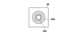
また、図5IVに示すように、赤色調整パターン22aおよび緑色調整パターン22bを表示することなく、青色調整パターン22cのみを表示した場合には、観察対象Sを透過した光のうち青色光の直接光が吸収されて減光され、赤色光および緑色光の直接光は透過するので、青色光の位相差画像のコントラストと黄色光の明視野画像の色特性を有する画像が得られる。
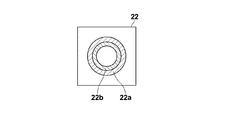
また、図5Vに示すように、赤色調整パターン22aおよび青色調整パターン22cを表示することなく、緑色調整パターン22bのみを表示した場合には、観察対象Sを透過した光のうち緑色光の直接光が吸収されて減光され、赤色光および青色光の直接光は透過するので、緑色光の位相差画像のコントラストと紫色光の明視野画像の色特性を有する画像が得られる。
また、図5VIに示すように、緑色調整パターン22bおよび青色調整パターン22cを表示することなく、赤色調整パターン22aのみを表示した場合には、観察対象Sを透過した光のうち赤色光の直接光が吸収されて減光され、緑色光および青色光の直接光は透過するので、上述したように赤色光の位相差画像のコントラストとみず色光の明視野画像の色特性を有する画像が得られる。
また、赤色調整パターン22a、緑色調整パターン22bおよび青色調整パターン22cの範囲を全て黒の表示とした場合には、従来の黒色のスリットを有する位相板を用いた場合と同様の位相差画像が撮像される。
図1に戻り、結像レンズ24は、透過型表示部22および位相板23を通過した直接光および回折光が入射され、これらの光を撮像部30に結像するものである。
撮像部30は、結像レンズ24によって結像された画像を撮像する撮像素子を備えたものである。撮像素子としては、CCD(charge-coupled device)イメージセンサやCMOS(Complementary Metal-Oxide Semiconductor)イメージセンサなどが用いられる。なお、本実施形態では、上述したように透過型表示部22において赤色光、緑色光および青色光の透過濃度を調整するようにしているので、撮像素子としては、赤色フィルタ、緑色フィルタおよび青色フィルタからなるカラーフィルタを備えた撮像素子が用いられる。
顕微鏡制御装置40は、CPU(Central Processing Unit)やストレージデバイスを備えたコンピュータから構成されるものである。
顕微鏡制御装置40は、具体的には、図1に示すように、透過型表示部22の各パターンの表示を制御することによって、各色の光の透過濃度を制御する透過濃度制御部41と、ステージ駆動部62を制御するステージ制御部42とを備えている。
透過濃度制御部41は、ユーザが入力装置55を用いて設定入力した所望の位相差画像の種類の情報を受け付け、その情報に基づいて、透過型表示部22の各パターンの表示を制御するものである。具体的には、たとえばユーザは、入力装置55を用いて位相差画像のベースとなる色の設定入力を行う。位相差画像のベースとなる色とは、透過型表示部22における透過濃度を相対的に高くする色のことである。たとえば位相差画像のベースとなる色を赤色としたい場合には、その情報がユーザによって設定入力される。透過濃度制御部41は、ユーザによって設定入力された色の情報に基づいて、赤色の透過濃度が相対的に高くなるように透過型表示部22を制御する。具体的には、緑色調整パターン22bおよび青色調整パターン22cを表示することなく、赤色調整パターン22aのみを表示するように制御する。このように、透過濃度制御部41は、ユーザによって設定入力された位相差画像のベースとなる色の情報に応じて、透過型表示部22における各パターンの表示を制御する。
また、顕微鏡制御装置40は、撮像部30の撮像素子を駆動制御し、撮像素子から出力された画像信号を取得し、その画像信号に基づいて表示装置50に画像を表示させるものである。
顕微鏡制御装置40には、入力装置55と表示装置50とが接続されている。入力装置55は、キーボードやマウスなどの入力デバイスを備えたものであり、ユーザによる設定入力を受け付けるものである。特に、本実施形態における入力装置55は、上述したように透過型表示部22において相対的に透過濃度を高くする色の情報の設定入力を受け付けるものである。本実施形態においては、入力装置55が、本発明の波長選択受付部に相当するものである。
表示装置50は、液晶ディスプレイなどの表示デバイスから構成されるものであり、撮像部30において撮像された画像などを表示するものである。なお、表示装置50と入力装置55とをタッチパネルによって構成することにより兼用するようにしてもよい。
次に、本実施形態の顕微鏡システムの作用について、図6に示すフローチャートを参照しながら説明する。
まず、観察対象Sおよび培養液Cが収容された培養容器60がステージ61上に設置される(S10)。次に、ユーザが、入力装置55を用いて位相差画像のベースとなる色を選択して設定入力する(S12)。
ユーザによって設定入力された位相差画像のベースとなる色の情報は透過濃度制御部41に入力され、透過濃度制御部41は、入力された色の情報に基づいて、透過型表示部22に各色の調整パターンを表示させる(S14)。
そして、照明光照射部10からリング状照明光が出射され、培養容器60の観察対象Sに照射される(S16)。
観察対象Sを透過した光は、第2の対物レンズ21によって集光されて透過型表示部22および位相板23に入射される。
透過型表示部22に表示された調整パターンの色と位相板23の作用によって観察対象Sの位相差画像が形成され、さらにその位相差画像を形成する波長以外の波長の色の明視野画像が形成される。そして、これらの画像が結像レンズ24によって撮像部30に結像されることによって、位相差画像のコントラストと明視野画像の色特性を有する観察対象Sの画像が撮像部30によって撮像される(S18)。
撮像部30によって撮像された画像信号は、顕微鏡制御装置40に出力され、顕微鏡制御装置40は、入力された画像信号に基づいて、表示装置50に観察対象Sの画像を表示させる(S20)。
上記実施形態の顕微鏡システムによれば、位相差計測用照明光の照射によって観察対象Sを透過した光を透過型表示部22に入射させ、観察対象Sを透過した光に含まれる複数の波長の光毎に透過濃度が異なるパターンを透過型表示部22に表示させ、上記パターンが表示された透過型表示部22を透過した光を検出することによって観察対象Sを撮像する。これにより、相対的に透過濃度が高い波長の光については、上記パターンによって減光されるので位相差観察と同等の効果を得ることができ、相対的に透過濃度が低い波長の光については、上記パターンによって減光されないので明視野観察と同等の効果を得ることができる。すなわち、透過型表示部22を透過した光を検出することによって、観察対象Sの色とコントラストの両方が明瞭な画像を撮像することができる。
なお、上記実施形態においては、図5I~図5VIに示したような種々のパターンを透過型表示部22に表示可能としたが、必ずしもこれらの全てのパターンを表示可能としなくてもよく、いずれかのパターンの表示に固定するようにしてもよい。その場合、相対的に波長が短い光に対する透過濃度の方が、相対的に波長が長い光に対する透過濃度よりも高いパターンを表示することが望ましい。波長が短い光の方が回折角が小さく、コントラストをより明確にすることができるので、この光の透過濃度を高くし、位相差画像に対する寄与度を大きくすることが望ましい。
具体的には、青色光に対する透過濃度の方が赤色光および緑色光に対する透過濃度よりも高いパターンを表示することが望ましい。すなわち、図5IVに示すように、赤色調整パターン22aおよび緑色調整パターン22bを表示することなく、青色調整パターン22cのみを表示させることが望ましい。
また、上記実施形態においては、ユーザが位相差画像のベースとなる色の情報を設定入力するようにしたが、これに限らず、観察対象Sの種類の情報と透過型表示部22に表示させるパターンの種類の情報とを対応づけたテーブルを透過濃度制御部41に予め設定しておき、ユーザによって設定入力された観察対象Sの種類の情報に基づいて、透過型表示部22に表示させるパターンを制御するようにしてもよい。なお、観察対象Sの種類の情報としては、細胞の種類の情報やアルカリホスファターゼのような試薬の種類の情報などがある。
また、細胞の種類によって細胞内での光の散乱の程度が異なる場合があるので、細胞の種類の情報に応じて透過型表示部22に表示される各色のパターンの大きさを変更するようにしてもよい。具体的には、散乱が大きい細胞の場合ほど各色のパターンの径を大きくすればよい。
また、上記実施形態においては、赤色調整パターン22aと緑色調整パターン22bと青色調整パターン22cとを同心円状にそれぞれ異なる位置に表示させるようにしたが、これらのパターンの表示位置を同じ位置とし、ユーザにより設定入力された色の情報に基づいて、これらのパターンを切り替えて表示させるようにしてもよい。
また、上記実施形態において、ユーザによる位相差観察モードと明視野観察モードの設定入力を可能とし、位相差観察モードが設定入力された場合には、上述したように透過濃度制御部41が透過型表示部22に所望のパターンを表示させ、観察対象Sの位相差画像を撮像部30によって撮像するようにし、明視野観察モードが設定された場合には、透過濃度制御部41が透過型表示部22には何も表示せず、観察対象Sの明視野画像を撮像部30によって撮像するようにしてもよい。
また、上記実施形態においては、赤色調整パターン22a、緑色調整パターン22bおよび青色調整パターン22cを透過型表示部22に表示させるようにしたが、すなわちRGB(Red、Green、Blue)の光を吸収するパターンを表示させるようにしたが、シアン、マゼンダおよびイエローの光を吸収するパターンを表示させるようにしてもよい。その場合、撮像素子としては、シアン、マゼンダおよびイエローのカラーフィルタを有する補色系の撮像素子を用いるようにすればよい。
また、上記実施形態においては、観察対象に対して白色光からなる位相差計測用照明光を照射するようにしたが、これに限らず、たとえば細胞などの観察対象に対して励起光からなる位相差計測用照明光を照射し、細胞から発生せられる蛍光や試薬から発せられる蛍光などを検出して観察対象の蛍光画像を撮像するようにしてもよい。
10 照明光照射部
11 白色光源
12 スリット板
12a スリット
12b 遮光板
13 第1の対物レンズ
20 結像光学系
21 第2の対物レンズ
22 透過型表示部
22a 赤色調整パターン
22b 緑色調整パターン
22c 青色調整パターン
23 位相板
23a 位相リング
24 結像レンズ
30 撮像部
40 顕微鏡制御装置
41 透過濃度制御部
42 ステージ制御部
50 表示装置
55 入力装置
60 培養容器
61 ステージ
62 ステージ駆動部
11 白色光源
12 スリット板
12a スリット
12b 遮光板
13 第1の対物レンズ
20 結像光学系
21 第2の対物レンズ
22 透過型表示部
22a 赤色調整パターン
22b 緑色調整パターン
22c 青色調整パターン
23 位相板
23a 位相リング
24 結像レンズ
30 撮像部
40 顕微鏡制御装置
41 透過濃度制御部
42 ステージ制御部
50 表示装置
55 入力装置
60 培養容器
61 ステージ
62 ステージ駆動部
Claims (12)
- 観察対象に位相差計測用照明光を照射する照明光照射部と、
前記位相差計測用照明光の照射によって前記観察対象を透過した光が入射される透過型表示部とを備え、
前記透過型表示部が、前記観察対象を透過した光に含まれる複数の波長の光毎に透過濃度が異なるパターンを表示することを特徴とする顕微鏡装置。 - 前記透過型表示部が、前記複数の波長の光毎のパターンをそれぞれ異なる位置に表示する請求項1記載の顕微鏡装置。
- 前記透過型表示部が、前記複数の波長の光毎のパターンを同心円状に表示する請求項2記載の顕微鏡装置。
- 前記透過型表示部が、相対的に波長が短い光に対する透過濃度の方が、相対的に波長が長い光に対する透過濃度よりも高いパターンを表示する請求項1から3いずれか1項記載の顕微鏡装置。
- 前記透過型表示部が、青色光に対する透過濃度の方が赤色光および緑色光に対する透過濃度よりも高いパターンを表示する請求項4記載の顕微鏡装置。
- 相対的に透過濃度を高くする波長の光の選択を受け付ける波長選択受付部を備え、
前記透過型表示部が、前記波長選択受付部によって受け付けられた波長の光に応じて、前記パターンの各波長の光の透過濃度を変更する請求項1から5いずれか1項記載の顕微鏡装置。 - 前記複数の波長の光が、赤色光、緑色光および青色光である請求項1から6いずれか1項記載の顕微鏡装置。
- 前記透過型表示部が、前記パターンを表示する位相差観察モードと前記パターンを非表示とする明視野観察モードとを有する請求項1から7いずれか1項記載の顕微鏡装置。
- 前記透過型表示部が、前記位相差観察モードの場合において、前記位相差計測用照明光に含まれる全ての波長の光を遮光するパターンを表示する請求項8記載の顕微鏡装置。
- 前記パターンが、リング状のパターンである請求項1から9いずれか1項記載の顕微鏡装置。
- 前記位相差計測用照明光の照射によって前記観察対象を透過した光が入射され、該入射された光の位相をずらす位相変更部をさらに備えた請求項1から10いずれか1項記載の顕微鏡装置。
- 観察対象に位相差計測用照明光を照射し、
該位相差計測用照明光の照射によって前記観察対象を透過した光を透過型表示部に入射させ、
前記観察対象を透過した光に含まれる複数の波長の光毎に透過濃度が異なるパターンを前記透過型表示部に表示させ、
前記パターンが表示された透過型表示部を透過した光を結像することを特徴とする結像方法。
Priority Applications (3)
| Application Number | Priority Date | Filing Date | Title |
|---|---|---|---|
| KR1020187009428A KR20180049006A (ko) | 2015-10-07 | 2016-10-05 | 현미경 장치 및 결상 방법 |
| EP16853267.9A EP3361302A4 (en) | 2015-10-07 | 2016-10-05 | Microscope device and image-forming method |
| US15/946,332 US20180224646A1 (en) | 2015-10-07 | 2018-04-05 | Microscope apparatus and image forming method |
Applications Claiming Priority (2)
| Application Number | Priority Date | Filing Date | Title |
|---|---|---|---|
| JP2015199061A JP6562807B2 (ja) | 2015-10-07 | 2015-10-07 | 顕微鏡装置および結像方法 |
| JP2015-199061 | 2015-10-07 |
Related Child Applications (1)
| Application Number | Title | Priority Date | Filing Date |
|---|---|---|---|
| US15/946,332 Continuation US20180224646A1 (en) | 2015-10-07 | 2018-04-05 | Microscope apparatus and image forming method |
Publications (1)
| Publication Number | Publication Date |
|---|---|
| WO2017061110A1 true WO2017061110A1 (ja) | 2017-04-13 |
Family
ID=58488309
Family Applications (1)
| Application Number | Title | Priority Date | Filing Date |
|---|---|---|---|
| PCT/JP2016/004476 WO2017061110A1 (ja) | 2015-10-07 | 2016-10-05 | 顕微鏡装置および結像方法 |
Country Status (5)
| Country | Link |
|---|---|
| US (1) | US20180224646A1 (ja) |
| EP (1) | EP3361302A4 (ja) |
| JP (1) | JP6562807B2 (ja) |
| KR (1) | KR20180049006A (ja) |
| WO (1) | WO2017061110A1 (ja) |
Cited By (2)
| Publication number | Priority date | Publication date | Assignee | Title |
|---|---|---|---|---|
| JP2019124542A (ja) * | 2018-01-15 | 2019-07-25 | 株式会社東芝 | 光学検査装置及び光学検査方法 |
| JP7448609B2 (ja) | 2018-05-23 | 2024-03-12 | 株式会社東芝 | 光学検査装置、方法及びプログラム |
Families Citing this family (2)
| Publication number | Priority date | Publication date | Assignee | Title |
|---|---|---|---|---|
| WO2018198908A1 (ja) * | 2017-04-24 | 2018-11-01 | 国立研究開発法人理化学研究所 | 毛髪観察方法、位相差顕微鏡システム及びプレパラート |
| KR20220102324A (ko) * | 2021-01-12 | 2022-07-20 | 정홍준 | 투명 디스플레이 패널을 이용한 현미경의 투과광 형성장치 |
Citations (5)
| Publication number | Priority date | Publication date | Assignee | Title |
|---|---|---|---|---|
| JPH04254815A (ja) * | 1991-02-07 | 1992-09-10 | Fuji Photo Film Co Ltd | 走査型顕微鏡 |
| JPH10206740A (ja) * | 1997-01-23 | 1998-08-07 | Yokogawa Electric Corp | 共焦点装置 |
| JP2003121749A (ja) * | 2001-08-09 | 2003-04-23 | Olympus Optical Co Ltd | 顕微鏡 |
| JP2006512620A (ja) * | 2002-12-31 | 2006-04-13 | アプライド プリシジョン, エルエルシー | 波長特異的位相顕微鏡検査法 |
| JP2011007598A (ja) * | 2009-06-25 | 2011-01-13 | Nikon Corp | 測定顕微鏡および測定顕微鏡の接眼レンズ部 |
Family Cites Families (3)
| Publication number | Priority date | Publication date | Assignee | Title |
|---|---|---|---|---|
| GB648801A (en) * | 1948-07-29 | 1951-01-10 | Peter Milton Barham | Improvements in phase-contrast microscopy |
| JP2011248278A (ja) * | 2010-05-31 | 2011-12-08 | Nikon Corp | 位相差分散顕微鏡 |
| JP5761458B2 (ja) * | 2012-06-05 | 2015-08-12 | 株式会社ニコン | 顕微鏡装置 |
-
2015
- 2015-10-07 JP JP2015199061A patent/JP6562807B2/ja active Active
-
2016
- 2016-10-05 KR KR1020187009428A patent/KR20180049006A/ko not_active Application Discontinuation
- 2016-10-05 EP EP16853267.9A patent/EP3361302A4/en active Pending
- 2016-10-05 WO PCT/JP2016/004476 patent/WO2017061110A1/ja active Application Filing
-
2018
- 2018-04-05 US US15/946,332 patent/US20180224646A1/en not_active Abandoned
Patent Citations (5)
| Publication number | Priority date | Publication date | Assignee | Title |
|---|---|---|---|---|
| JPH04254815A (ja) * | 1991-02-07 | 1992-09-10 | Fuji Photo Film Co Ltd | 走査型顕微鏡 |
| JPH10206740A (ja) * | 1997-01-23 | 1998-08-07 | Yokogawa Electric Corp | 共焦点装置 |
| JP2003121749A (ja) * | 2001-08-09 | 2003-04-23 | Olympus Optical Co Ltd | 顕微鏡 |
| JP2006512620A (ja) * | 2002-12-31 | 2006-04-13 | アプライド プリシジョン, エルエルシー | 波長特異的位相顕微鏡検査法 |
| JP2011007598A (ja) * | 2009-06-25 | 2011-01-13 | Nikon Corp | 測定顕微鏡および測定顕微鏡の接眼レンズ部 |
Non-Patent Citations (1)
| Title |
|---|
| See also references of EP3361302A4 * |
Cited By (2)
| Publication number | Priority date | Publication date | Assignee | Title |
|---|---|---|---|---|
| JP2019124542A (ja) * | 2018-01-15 | 2019-07-25 | 株式会社東芝 | 光学検査装置及び光学検査方法 |
| JP7448609B2 (ja) | 2018-05-23 | 2024-03-12 | 株式会社東芝 | 光学検査装置、方法及びプログラム |
Also Published As
| Publication number | Publication date |
|---|---|
| JP6562807B2 (ja) | 2019-08-21 |
| EP3361302A4 (en) | 2018-11-07 |
| EP3361302A1 (en) | 2018-08-15 |
| JP2017072700A (ja) | 2017-04-13 |
| KR20180049006A (ko) | 2018-05-10 |
| US20180224646A1 (en) | 2018-08-09 |
Similar Documents
| Publication | Publication Date | Title |
|---|---|---|
| WO2017061110A1 (ja) | 顕微鏡装置および結像方法 | |
| US9069175B2 (en) | Adaptive phase contrast microscope | |
| US10754138B2 (en) | Multi-well fourier ptychographic and fluorescence imaging | |
| CN104765138B (zh) | 基于led阵列的多模式显微成像系统及其方法 | |
| CN110023812B (zh) | 单平面照明显微镜 | |
| US20120057013A1 (en) | Method and apparatus for visualizing phase object | |
| CN105158887A (zh) | 基于可编程led阵列照明的多模式显微成像方法 | |
| JPWO2016125281A1 (ja) | 構造化照明顕微鏡、観察方法、及び制御プログラム | |
| CN105158888A (zh) | 基于lcd液晶面板的可编程显微镜聚光镜装置及其成像方法 | |
| CN109407297B (zh) | 一种基于可编程led阵列照明的多模式光场显微成像方法 | |
| TW201403122A (zh) | 顯微鏡裝置 | |
| WO2017145487A1 (ja) | 顕微鏡および観察方法 | |
| CN103529542A (zh) | 偏振光调制相衬显微镜 | |
| JP2009009139A (ja) | 波長特異的位相顕微鏡検査法 | |
| US11268906B2 (en) | Microscope and method for observing biological specimen in living state | |
| CN203561790U (zh) | 一种偏振光调制相衬显微镜 | |
| US20090097110A1 (en) | Polarized phase microscopy | |
| JP2020085988A (ja) | 顕微鏡装置 | |
| JP6371686B2 (ja) | 観察対象抽出処理装置、方法およびプログラム並びに観察画像撮像表示システム | |
| WO2015129138A1 (ja) | 観察装置 | |
| JP2016161610A (ja) | 撮像装置および方法 | |
| JP6534294B2 (ja) | 撮像装置および方法並びに撮像制御プログラム | |
| JP6587709B2 (ja) | 観察対象抽出処理装置、方法およびプログラム並びに観察画像撮像表示システム | |
| JP6269096B2 (ja) | 顕微鏡装置および顕微鏡システム | |
| WO2016132563A1 (ja) | 標本観察装置及び標本観察方法 |
Legal Events
| Date | Code | Title | Description |
|---|---|---|---|
| 121 | Ep: the epo has been informed by wipo that ep was designated in this application |
Ref document number: 16853267 Country of ref document: EP Kind code of ref document: A1 |
|
| ENP | Entry into the national phase |
Ref document number: 20187009428 Country of ref document: KR Kind code of ref document: A |
|
| NENP | Non-entry into the national phase |
Ref country code: DE |
|
| WWE | Wipo information: entry into national phase |
Ref document number: 2016853267 Country of ref document: EP |