WO2017056874A1 - ターボファンおよびそれを用いた空気調和機 - Google Patents
ターボファンおよびそれを用いた空気調和機 Download PDFInfo
- Publication number
- WO2017056874A1 WO2017056874A1 PCT/JP2016/076156 JP2016076156W WO2017056874A1 WO 2017056874 A1 WO2017056874 A1 WO 2017056874A1 JP 2016076156 W JP2016076156 W JP 2016076156W WO 2017056874 A1 WO2017056874 A1 WO 2017056874A1
- Authority
- WO
- WIPO (PCT)
- Prior art keywords
- blade
- air flow
- hub
- shroud
- curved surface
- Prior art date
- Legal status (The legal status is an assumption and is not a legal conclusion. Google has not performed a legal analysis and makes no representation as to the accuracy of the status listed.)
- Ceased
Links
Images


Classifications
-
- F—MECHANICAL ENGINEERING; LIGHTING; HEATING; WEAPONS; BLASTING
- F04—POSITIVE - DISPLACEMENT MACHINES FOR LIQUIDS; PUMPS FOR LIQUIDS OR ELASTIC FLUIDS
- F04D—NON-POSITIVE-DISPLACEMENT PUMPS
- F04D29/00—Details, component parts, or accessories
- F04D29/26—Rotors specially for elastic fluids
- F04D29/28—Rotors specially for elastic fluids for centrifugal or helico-centrifugal pumps for radial-flow or helico-centrifugal pumps
- F04D29/30—Vanes
-
- F—MECHANICAL ENGINEERING; LIGHTING; HEATING; WEAPONS; BLASTING
- F04—POSITIVE - DISPLACEMENT MACHINES FOR LIQUIDS; PUMPS FOR LIQUIDS OR ELASTIC FLUIDS
- F04D—NON-POSITIVE-DISPLACEMENT PUMPS
- F04D29/00—Details, component parts, or accessories
- F04D29/26—Rotors specially for elastic fluids
- F04D29/28—Rotors specially for elastic fluids for centrifugal or helico-centrifugal pumps for radial-flow or helico-centrifugal pumps
- F04D29/281—Rotors specially for elastic fluids for centrifugal or helico-centrifugal pumps for radial-flow or helico-centrifugal pumps for fans or blowers
- F04D29/282—Rotors specially for elastic fluids for centrifugal or helico-centrifugal pumps for radial-flow or helico-centrifugal pumps for fans or blowers the leading edge of each vane being substantially parallel to the rotation axis
-
- F—MECHANICAL ENGINEERING; LIGHTING; HEATING; WEAPONS; BLASTING
- F24—HEATING; RANGES; VENTILATING
- F24F—AIR-CONDITIONING; AIR-HUMIDIFICATION; VENTILATION; USE OF AIR CURRENTS FOR SCREENING
- F24F1/00—Room units for air-conditioning, e.g. separate or self-contained units or units receiving primary air from a central station
-
- F—MECHANICAL ENGINEERING; LIGHTING; HEATING; WEAPONS; BLASTING
- F05—INDEXING SCHEMES RELATING TO ENGINES OR PUMPS IN VARIOUS SUBCLASSES OF CLASSES F01-F04
- F05D—INDEXING SCHEME FOR ASPECTS RELATING TO NON-POSITIVE-DISPLACEMENT MACHINES OR ENGINES, GAS-TURBINES OR JET-PROPULSION PLANTS
- F05D2240/00—Components
- F05D2240/20—Rotors
- F05D2240/30—Characteristics of rotor blades, i.e. of any element transforming dynamic fluid energy to or from rotational energy and being attached to a rotor
- F05D2240/303—Characteristics of rotor blades, i.e. of any element transforming dynamic fluid energy to or from rotational energy and being attached to a rotor related to the leading edge of a rotor blade
-
- F—MECHANICAL ENGINEERING; LIGHTING; HEATING; WEAPONS; BLASTING
- F05—INDEXING SCHEMES RELATING TO ENGINES OR PUMPS IN VARIOUS SUBCLASSES OF CLASSES F01-F04
- F05D—INDEXING SCHEME FOR ASPECTS RELATING TO NON-POSITIVE-DISPLACEMENT MACHINES OR ENGINES, GAS-TURBINES OR JET-PROPULSION PLANTS
- F05D2240/00—Components
- F05D2240/20—Rotors
- F05D2240/30—Characteristics of rotor blades, i.e. of any element transforming dynamic fluid energy to or from rotational energy and being attached to a rotor
- F05D2240/304—Characteristics of rotor blades, i.e. of any element transforming dynamic fluid energy to or from rotational energy and being attached to a rotor related to the trailing edge of a rotor blade
Definitions
- the present invention relates to a turbofan that blows air that has been axially sucked from the shroud side in the radial direction and blows it out, and an air conditioner using the same.
- the turbo fan is composed of a hub that is rotationally driven by a motor or the like, a shroud disposed opposite to the hub, and a plurality of blades disposed between the hub and the shroud. Many of the blades of this turbo fan are disposed between the hub and the shroud in the rotational direction side of the trailing edge, which is the end on the inner circumferential side, than the trailing edge, which is the outer circumferential end.
- the cross-sectional shape is generally a two-dimensional shape that is uniform in the axial direction due to molding restrictions and the like (see, for example, Patent Document 1).
- Patent Document 1 shows a two-dimensional shape that is uniform in the axial direction due to molding restrictions and the like.
- Patent Document 5-7 for example, in order to suppress the horseshoe vortices generated at the connection portion between the hub and the blade, as shown in Patent Document 5-7, for example, as shown in Patent Document 5-7.
- the vicinity of the hub side front edge has a curved structure in the direction of rotation or counter-rotation, and a horseshoe-shaped vortex suppressor is formed, or a part of the blades is counter-rotated to form a dead water reduction space between the blades and the shroud.
- the air flow sucked in from the outer edge side of the suction port is not bent by the inertia force, and the flow is biased toward the hub side internally because the air flow sucked in in the axial direction is turned in the radial direction.
- the blade is not effective at locations close to the suction port, resulting in a drop in efficiency, high-speed jet flow due to uneven air flow on the blowout side, backflow near the suction port, and noise It was easy to grow.
- a turbofan is used in an air conditioner, air is drawn from a square passage passing through a grill or a filter, and the air outlet side is operated with a non-axisymmetric pressure field surrounded by a square heat exchanger. It is difficult to achieve uniform flow over the entire span direction (axial direction) of the fan, and as described above, various ideas have been proposed aiming at noise reduction and high efficiency.
- JP 2002-235695 A JP 2007-170331 A JP 2007-170771 A Unexamined-Japanese-Patent No. 2010-216486 JP, 2009-127541, A WO 2009/069606 WO 2010/128618
- the turbo fan when the fan input which is the driving force of the turbo fan is used as an evaluation parameter, the turbo fan still has room for improvement.
- reducing the fan input is an eternal problem, and from such a point of view, when the fluid flow analysis of the turbo fan by the finite volume method is performed, in the current turbo fan, the negative pressure surface of the outer peripheral side (rear edge side) of the blade While the air flow along the blade tends to separate from the blade surface, a high static pressure region is generated on the pressure surface side of the blade, which causes the air flow along the blade to decelerate (a loss of driving force) ) And found that the fan efficiency has dropped.
- the present invention has been made in view of such circumstances, and suppresses the separation of the air flow on the negative pressure surface on the outer peripheral side (rear edge side) of the blade and also reduces the air flow on the pressure surface side of the blade. It is an object of the present invention to provide a turbofan capable of improving fan efficiency and reducing fan input which is a driving force of the fan and an air conditioner using the same.
- the turbo fan of the present invention and an air conditioner using the same adopt the following means. That is, according to the first aspect of the present invention, there is provided a hub connected to a motor drive shaft and driven to rotate, an annular shroud disposed opposite to the hub and forming an air inlet, and between the hub and the shroud And the plurality of blades are disposed such that the front edge on the inner peripheral side is disposed on the rotational direction side with respect to the rear edge on the outer peripheral side, the plurality of blades being the rear edge Is a turbo fan characterized in that it is concave in the direction of air flow with respect to the connection to the hub and the shroud.
- the trailing edges (also referred to as trailing edge lines) of the plurality of blades are recessed in the direction opposite to the air flow with respect to the coupling portion to the hub and the shroud, the trailing edge lines of the blades are straight As compared with the one having a shape like or convex in the air flow direction, the separation of the air flow on the negative pressure surface side of the blade can be improved, the disturbance of the air flow can be suppressed, and the pressure on the pressure surface side of the blade It is possible to improve fan efficiency and reduce the driving force (fan input) of the fan by reducing the generated high static pressure region and suppressing the deceleration of the air flow (the loss of the driving force).
- the radius of the concave region becomes smaller than the original shape, and when the fan is rotated at the same rotational speed, the air passing through the fan
- the pressure rise of the flow can be reduced, which makes the air flow easier to flow as the pressure (static pressure) near the trailing edge of the blade is reduced at the suction surface, especially at the easily peelable point on the shroud side.
- the separation can be suppressed, on the positive pressure surface, the air flow passing through the fan has a significant effect of being biased toward the hub side, and the pressure on the blade surface also exhibits a sharp increase toward the hub side.
- the pressure (static pressure) near the trailing edge of the blade can be reduced, the static pressure on the positive pressure surface can be reduced, the fan efficiency can be improved, and the fan input can be reduced. is there. Therefore, it is possible to further increase the efficiency and reduce the noise of the turbo fan.
- the trailing edge of the blade is opposite to the air flow direction as described above, with the central portion in the span direction of the blade being in the range of 25% to 75% of the span direction. It may be concave.
- the central portion of the trailing edge line of the blade is recessed in the direction opposite to the air flow in the range of 25 to 75% of the span direction of the blade, the function of the connection of the blade to the hub and shroud The vanes can be coupled to the hub and shroud without affecting performance. Therefore, the air flow is not disturbed at the hub side coupling portion and the shroud side coupling portion of the blades, and noise reduction and high efficiency can be achieved.
- the concave amount (indicated by-) of the trailing edge of the blade in the direction opposite to the air flow is -0.0142 D to the fan outer diameter D. It may be in the range of -0.0153D.
- the amount of concave (-display) in the anti-air flow direction of the trailing edge line of the blade is in the range of -0.0142 D to -0.0153 D with respect to the fan outer diameter D.
- the fan input which is the driving force of the turbo fan can be reduced to a preferable range. Therefore, it is possible to increase the efficiency and reduce the noise of the turbo fan.
- the leading edge of the blade is concaved in the air flow direction or convexed in the airflow direction with respect to the coupling portion to the hub and the shroud. It may be
- the leading edge (also referred to as a leading edge line) of the blade is concaved in the air flow direction or convex in the opposite air flow direction with respect to the joint to the hub and the shroud.
- a leading edge line By slightly displacing the air flow direction in the air flow direction, slight disturbance may occur in the air flow on the suction surface of the blade, but the high static pressure area on the pressure surface is reduced to suppress the air flow deceleration.
- the high static pressure region on the positive pressure surface side may be slightly enlarged by slightly displacing the leading edge line in the direction opposite to the air flow, and the effect of suppressing air flow deceleration may be slightly reduced.
- the disturbance of the air flow on the negative pressure surface can be suppressed to suppress the separation.
- the leading edge line of the blade concave in the air flow direction by making the leading edge line of the blade concave in the air flow direction, the length in the air flow direction of the blade can be shortened, the friction loss between the air flow and the blade surface can be reduced, and the fan input can be reduced.
- the shape is too concave, the blade length in the air flow direction relative to the distance between adjacent blades becomes too short, and blade performance deteriorates.
- the concave amount (indicated by +) in the air flow direction of the front edge of the blade is in the range of 0.0091 D to 0.0153 D with respect to the fan outer diameter D.
- the convex amount in the direction opposite to the air flow (-indication) may be -0.0438 D with respect to the fan outer diameter D.
- the concave amount (+ indication) in the air flow direction of the leading edge line is in the range of 0.0091 D to 0.0153 D with respect to the fan outer diameter D
- the convex in the anti-air flow direction (-Indication) is -0.0438 D with respect to the fan outer diameter D
- the air in the span direction of the blade is in the range 25% to 75% of the span direction. It may be concave in the flow direction or convex in the anti-air flow direction.
- the central portion of the leading edge line of the blade is recessed in the direction of air flow or convex in the direction of air flow within a range of 25% to 75% of the span direction of the blade.
- the vanes can be coupled to the hub and the shroud without affecting the function and performance of the connection to the hub and the shroud. Therefore, the air flow is not disturbed at the hub side coupling portion and the shroud side coupling portion of the blades, and noise reduction and high efficiency can be achieved.
- connection of the blade to the hub is a smooth curved surface in the opposite rotational direction
- connection of the blade to the shroud is a rotary It may be a smooth curved surface in the direction.
- connection between the blade and the hub is a smooth curved surface in the opposite rotational direction
- connection between the blade and the shroud is a smooth curved surface in the rotational direction.
- the angle (+ display) of the curved surface in the opposite rotational direction of the coupling portion of the blade to the hub is 0. 0 with respect to one pitch angle ⁇ of the blade.
- the angle (-indication) of the curved surface in the rotational direction of the joint with respect to the shroud is -0.0154.theta. To -0.0972.theta. With respect to one pitch angle .theta. It may be in the range of
- the angle (+ display) of the curved surface in the opposite rotational direction of the coupling portion of the blade to the hub is set in the range of 0.0563 ⁇ to 0.0972 ⁇ with respect to one pitch angle ⁇ of the blade, Since the angle (-indication) of the curved surface in the rotational direction of the joint with respect to the shroud is in the range of -0.0154 ⁇ to -0.0972 ⁇ with respect to one pitch angle ⁇ of the blade, the hub side joint It is possible to suppress stagnation of the air flow at the same time, and to suppress separation of the air flow on the negative pressure surface side by the wing force to further improve the blade performance. Therefore, the fan input which is the driving force of the turbo fan can be reduced to a preferable range, and the turbo fan can be made highly efficient and low in noise.
- connection of the blade to the hub is a smooth curved surface in the rotational direction
- connection of the blade to the shroud is anti-rotation It may be a smooth curved surface in the direction.
- connection between the blade and the hub is a smooth curved surface in the rotational direction
- connection between the blade and the shroud is a smooth curved surface in the opposite rotational direction.
- the angle (indicated by-) of the curved surface in the rotational direction of the coupling portion of the blade to the hub is -0.
- the angle (plus sign) of the curved surface in the opposite rotational direction of the joint with respect to the shroud may be 0.0031 ⁇ with respect to one pitch angle ⁇ of the blade.
- the angle (-indication) of the curved surface in the rotational direction of the coupling portion of the blade to the hub is ⁇ 0.0768 ⁇ with respect to one pitch angle ⁇ of the blade, and the coupling to the shroud Since the angle (+ display) of the curved surface in the counter-rotation direction of the part is 0.0031 ⁇ with respect to one pitch angle ⁇ of the blades, the stagnation of the air flow at the hub side joint part is suppressed It is possible to suppress the separation of the air flow on the suction surface side in the vicinity of the shroud and to further improve the blade performance. Therefore, the fan input which is the driving force of the turbo fan can be reduced to a preferable range, and the turbo fan can be made highly efficient and low in noise.
- the coupling portion of the blade to the hub is a smooth curved surface in the rotational direction
- the coupling portion of the blade to the shroud is the rotational direction. It may be a smooth curved surface.
- connection between the blade and the hub is a smooth curved surface in the rotational direction
- connection between the blade and the shroud is a smooth curved surface in the rotational direction.
- the angle (indicated by-) of the curved surface in the rotational direction of the coupling portion of the blade to the hub is -0.
- the angle (-indication) of the curved surface in the rotational direction of the connecting portion with respect to the shroud may be ⁇ 0.0461 ⁇ with respect to one pitch angle ⁇ of the blade.
- the angle (-indication) of the curved surface in the rotational direction of the connection of the blade to the hub is -0.0154 ⁇ with respect to one pitch angle ⁇ of the blade
- the rotation of the connection to the shroud is Since the angle (-display) of the curved surface in the direction is -0.0461 ⁇ with respect to the 1 pitch angle ⁇ of the blade, stagnation of air flow at the hub side joint portion can be suppressed.
- the separation of the air flow on the suction side can be suppressed by the blade force, and the blade performance can be further improved. Therefore, the fan input which is the driving force of the turbo fan can be reduced to a preferable range, and the turbo fan can be made highly efficient and low in noise.
- the second aspect of the present invention comprises a blower for sucking and blowing out indoor air, and a heat exchanger disposed on either the suction side or the blowing side of the blower for cooling or heating the indoor air.
- the air conditioner is characterized in that the blower is any one of the above-described turbofans.
- the blower that sucks in the indoor air and cools or heats it with the heat exchanger and blows out the temperature-controlled air into the room is any of the above-described turbofans
- the driving force of the turbofan The fan input can be reduced to improve the efficiency and noise of the turbo fan. Therefore, the air conditioner can be further improved in performance and noise.
- turbo fan of the present invention it is possible to improve the separation of the air flow on the suction side of the blade and suppress the turbulence of the air flow, and reduce the high static pressure region generated on the pressure side of the blade. Since the fan efficiency can be improved and the driving force (fan input) of the fan can be reduced by suppressing the deceleration of the air flow (the loss of the driving force), the efficiency of the turbo fan can be further enhanced and the noise can be reduced. Can be
- the fan input which is the driving force of the turbo fan can be reduced, and the turbo fan can be made high efficiency and low noise, so the air conditioner can be further enhanced in performance and low in noise.
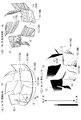
- FIG. 1 It is an exploded perspective view of an air conditioner concerning one embodiment of the present invention. It is a figure which shows fan shape (A) of the turbo fan applied to the said air conditioner, the limit flow line (B) in the blade
- FIG. 1 An exploded perspective view of an air conditioner according to an embodiment of the present invention is shown in FIG.
- the air conditioner 1 according to the present embodiment is a ceiling-embedded air conditioner 1
- the present invention is not limited to the ceiling-embedded air conditioner 1, and other types of air conditioners Of course, it may be applied to 1.
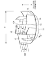
- the ceiling-embedded air conditioner 1 includes a substantially square unit body 2 suspended by a bolt or the like in a ceiling, an indoor air inlet 4 and a temperature-controlled air outlet provided on the lower surface of the unit body 2. 5, a bell mouth 6 disposed in the unit body 2 so as to face the room air inlet 4 of the ceiling panel 3 and a unit body 2 so as to face the bell mouth 6 And a rectangular heat exchanger 8 installed in the unit main body 2 so as to surround the turbo fan 7 (blower).
- the turbo fan 7 is connected to a motor 9 fixedly installed on the top plate of the unit body 2, a rotating shaft 9 A of the motor 9, and a hub (main plate) 10 rotationally driven by the motor 9, a hub (main plate) 10 and Casingless comprising an annular shroud (side plate) 11 disposed opposite to each other, and a plurality of blades 12 disposed with both ends coupled to the hub (main plate) 10 and the shroud (side plate) 11, respectively.
- the plurality of blades 12 of the turbofan 7 have a front edge (sometimes referred to as a leading edge line) 13 on the inner circumferential side with respect to a trailing edge (sometimes referred to as a trailing edge line) 14 on the outer circumferential side. Is disposed on the rotational direction N side.
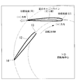
- the turbo fan 7 of the present embodiment is a modification of the shape of the blade 12 as described later, whereby the air flow on the negative pressure surface 15 side of the blade 12 can be reduced as shown in FIG.
- FIG. 2B a sharp streamline with few sharp changes in the distance (without peeling) as in the critical streamline shown in FIG.
- FIG. 2C the static pressure on the air side is eliminated or reduced as much as possible in the high static pressure region to suppress deceleration (loss) of the air flow. It is intended to reduce the fan input which is the driving force.
- the turbo fan 7 in order to evaluate the performance of the turbo fan 7 using the fan input which is the driving force of the turbo fan 7 as a parameter, the turbo fan 7 is analyzed by the finite volume method with the air conditioner 1 attached.
- the shape of the wing 12 is set.
- (1) displacement (movement amount) of the front edge 13 of the blade 12, (2) displacement (movement amount) of the trailing edge 14 of the blade 12 3) Curved (rotational angle) of hub-side joint 17 of blade 12 (4) Curved (rotational angle) of shroud-side joint 18 of blade 12 as a design variable I made an evaluation.
- the optimum shape (No. 59) was determined based on the first shape (No. 31) in the parameter study.
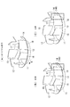
- Figures 2 (A) and 3 (A) to 3 (E) show that the fan with the optimal shape (No. 59) and the 41 cases evaluated by the parameter study were evaluated 1st (No. 31) and 2nd (No. 32), the fan of the third place (No. 06), the fan of the original shape as the evaluation standard (No. 0), and the shape of the fan (No. 14) of the lowest evaluation (the 41st place) It is shown.
- the detailed shape of the fan shown in FIG. 2 (A) and FIGS. 3 (A) to 3 (E) will be described later, but as for the fan of the original shape, as shown in FIG.
- the fan shape 14 has a front edge line 13 of the blade 12 made concave 13A in the air flow direction with respect to the original fan shape shown in FIG. 3 (D).
- the line 14 has a convex shape 14B in the air flow direction
- the hub side joint portion 17 has a curved surface 17A curved in the reverse rotational direction
- the shroud side joint portion 18 has a curved surface 18A curved in the reverse rotational direction. It is done.
- the limit flow lines of the fans corresponding to the fan shapes shown in (A) to (E) of FIG. A diagram comparing the static pressure contour and the static pressure contour is shown.
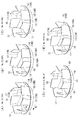
- the displacement (displacement amount) of the front edge 13 of the blade 12 corresponds to the original shape shown in FIG. 6A in which the front edge 13 of the blade 12 is linear as shown in FIG.
- the leading edge line 13 is concaved in the air flow direction with respect to the coupling portions 17 and 18 to the hub 10 and the shroud 11 (the displacement is indicated by +), or FIG.
- the convex 13 B moving amount is indicated-
- the convex 13 B moving amount is indicated-
- the curvature (rotational angle) of the hub-side coupling portion 17 of the blade 12 refers to the case where the hub-side coupling portion 17 of the blade 12 is coupled substantially perpendicularly to the hub 10 as shown in FIG.
- the hub 10 when the hub side coupling portion 17 of the blade 12 is a curved surface 17A curved in the anti-rotation direction (counterclockwise direction).
- the connecting portions 17 and 18 of the blade 12 to the hub 10 and the shroud 11 are such that the entire blade is with respect to the center O of the rotation shaft 9A so that the angle between the blade 12 and the air flow does not change. It is curved in the reverse rotation direction (counterclockwise direction) or in the rotation direction (clockwise direction).
- the displacement (moving amount) of the front edge 13 and the rear edge 14 of the blade 12 is such that the outer diameter direction of the blade 12 is the + direction, and the camber line of the blade (blade) 12 And on its extension, it is made to be displaced in a concave or convex shape. That is, as shown in FIG. 12, the displacement of the front edge 13 and the rear edge 14 of the blade 12 is substantially equal to the blade height in the span direction (rotational axis direction) on both the front edge 13 side and the rear edge 14 side. It is moved by the same amount along the camber line (camber line) in the range of 25% to 75%, and is made concave or convex.
- the hub 10 and the shroud 11 are connected by smooth curves.
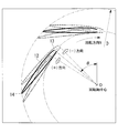
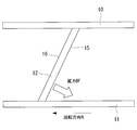
- FIG. 13 illustrates the wing force BF of the turbo fan 7.
- the wing force BF of the turbofan 7 corresponds to a pressure gradient acting between a plurality of blades (blades 12), and is a force exerted on the air flow which is the fluid, and as shown in FIG.
- the blade force BF acts in a direction perpendicular to the wing surface by inclining the).
- the wing force BF functions to suppress the separation on the negative pressure surface side by pressing the air flow against the wall surface (the wall surface of the shroud 11 in FIG. 13).
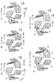
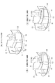
- FIG. 5 is a perspective view of a turbofan 7 with vanes 12 of the 59 optimum configuration.
- the leading edge line 13 has a concave shape 13A (see FIG. 6B) in the air flow direction
- the trailing edge line 14 has a concave shape 14A (see FIG. 7B) in the air flow direction. It is supposed to be configured.
- the connecting portion (hub-side connecting portion) 17 of the blade 12 to the hub 10 is a curved surface 17A (see FIG. 8B) that curves in the anti-rotation direction (counterclockwise direction).
- the coupling portion (shroud side coupling portion) 18 to the shroud 11 is configured as a curved surface 18B (see FIG. 9C) that curves in the rotational direction (clockwise direction).
- the entire blade is curved with respect to the rotation axis O so that the angle between the blade 12 and the air flow does not change. ing.
- leading edge line 13 and the trailing edge line 14 have center portions in the span direction (rotational axis direction) of the blades 12 in the range of 25 to 75% of the span direction dimension
- the leading edge line 13 is concaved 13A in the air flow direction and the trailing edge line 14 is concaved 14A in the opposite air flow direction by being moved by the same amount along the camber line of the wing (wing) 12 and its extension. It is supposed to be configured.
- the curvature (rotation angle) of the hub-side coupling portion 17 of the blade 12 is made to be a curved surface 17A of 0.0972 ⁇ in the reverse rotation direction (counterclockwise direction, + display), and (4) the blade 12
- the curvature (rotation angle) of the shroud-side joint portion 18 is a curved surface 18B of -0.0972 ⁇ in the rotational direction (clockwise direction,-display).
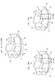
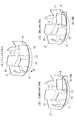
- FIG. 3 A perspective view of a turbofan 7 with a 31 (first place) blade shape is shown.
- the leading edge line 13 is concaved in the air flow direction 13 A (see FIG. 6B)
- the trailing edge line 14 is concaved in the opposite air flow direction 14 A ( It is set as the structure made into FIG. 7 (B).
- the connecting portion (hub-side connecting portion) 17 of the blade 12 to the hub 10 is a curved surface 17A (see FIG. 8B) that curves in the anti-rotation direction (counterclockwise direction).
- the coupling portion (shroud side coupling portion) 18 to the shroud 11 is configured as a curved surface 18B (see FIG. 9C) that curves in the rotational direction (clockwise direction).
- the entire blade is curved with respect to the rotation axis O so that the angle between the blade 12 and the air flow does not change. ing.
- leading edge line 13 and the trailing edge line 14 are vanes in the span direction (rotational axis direction) central portion of the vane 12 in the range of 25 to 75% of the spanwise dimension.
- the leading edge line 13 is made concave 13A in the air flow direction
- the trailing edge line 14 is made concave 14A in the opposite air flow direction by being moved by the same amount along the camber line of the (wing) 12 and its extension. It is considered to be
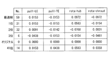
- the above-mentioned design variables (1) to (4) are, as shown in the table of FIG. 15, (1) displacement (movement amount of the leading edge (pull-LE) 13 of the blade 12 Is a concave 13A equivalent to 0.0153 D with respect to the air flow direction (+ display), and (2) the displacement (movement amount) of the trailing edge (pull-TE) 14 of the blade 12 is the anti-air flow direction -Indicated a concave 14A equivalent to -0.0153D.
- the curvature (rotational angle) of the hub-side coupling portion 17 of the blade 12 is a curved surface 17A of 0.0563 ⁇ in the reverse rotation direction (counterclockwise direction, + display), and (4) the blade 12
- the curvature (rotation angle) of the shroud-side joint portion 18 is a curved surface 18B of ⁇ 0.0154 ⁇ in the rotation direction (clockwise direction, ⁇ display).
- FIG. 3 A perspective view of a turbofan 7 with a 32 (2nd) blade shape is shown.
- the leading edge line 13 is concaved in the air flow direction 13 A (see FIG. 6B)
- the trailing edge line 14 is concaved in the opposite air flow direction 14 A ( It is set as the structure made into FIG. 7 (B).
- the connecting portion (hub side connecting portion) 17 of the blade 12 to the hub 10 is a curved surface 17B (see FIG. 8C) curved in the rotational direction (clockwise direction).
- the coupling portion (shroud side coupling portion) 18 is configured to be a curved surface 18A (see FIG. 9B) that curves in the counter-rotation direction (counterclockwise direction).
- the entire blade is curved with respect to the rotation axis O so that the angle between the blade 12 and the air flow does not change. ing.
- leading edge line 13 and the trailing edge line 14 are vanes in the span direction (rotational axis direction) central portion of the vane 12 in the range of 25 to 75% of the spanwise dimension.
- the curve (rotation angle) of the hub-side joint 17 of the blade 12 of (3) is a curved surface 17B of -0.0768 ⁇ in the rotational direction (clockwise direction,-display), and the blade of (4)
- the curvature (rotational angle) of the twelve shroud side coupling portions 18 is taken as a curved surface 18A of 0.0031 ⁇ in the reverse rotation direction (counterclockwise direction, + display).
- FIG. 3 A perspective view of a turbofan 7 with a 06 (3rd) blade shape is shown.
- the leading edge line 13 has a convex shape 13B (see FIG. 6C) in the air flow direction
- the trailing edge line 14 has a concave shape 14A in the air flow direction (see FIG. 7B).
- the composition it is considered to be the composition.
- the connecting portion (hub side connecting portion) 17 of the blade 12 to the hub 10 is a curved surface 17B (see FIG. 8C) curved in the rotational direction (clockwise direction).
- the coupling portion (shroud side coupling portion) 18 is configured to be a curved surface 18B (see FIG. 9C) that curves in the counter-rotation direction (counterclockwise direction).
- the entire blade is curved with respect to the rotation axis O so that the angle between the blade 12 and the air flow does not change. ing.
- leading edge line 13 and the trailing edge line 14 are vanes in the span direction (rotational axis direction) central portion of the vane 12 in the range of 25 to 75% of the spanwise dimension.
- the leading edge line 13 is convex 13B in the opposite air flow direction and the trailing edge line 14 is concave 14A in the opposite air flow direction. It is supposed to be configured.
- the curve (rotation angle) of the hub-side coupling portion 17 of the blade 12 of (3) is a curved surface 17B of ⁇ 0.0154 ⁇ in the rotational direction (clockwise direction,-display), and the blade of (4)
- the curvature (rotational angle) of the twelve shroud side coupling portions 18 is a curved surface 18B of -0.0461 ⁇ in the rotational direction (clockwise direction,-indication).
- the room air sucked from the room air suction port 4 of the ceiling panel 3 by the rotation of the turbo fan 7 is an opening on the shroud 11 side of the turbo fan 7 via the bell mouth 6. It is sucked in from the axial direction.
- the air flow taken in by the turbo fan 7 is directed in the radial direction by the plurality of blades 12 and blown out, and is cooled in the process of passing through the heat exchanger 8 disposed so as to surround the turbo fan 7 Alternatively, by being heated, the air is blown out into the room from the four temperature control outlets 5 provided on the four sides of the ceiling panel 3 as the temperature control wind, and the room is air-conditioned.
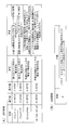
- the turbo fan 7 performs fluid analysis by the finite volume method parametrically using the four items (1) to (4) shown in FIG.
- the shape of the blade 12 is set based on the value of the variable.
- the definition of the objective function D ' is shown in FIG. 14 (B).
- the list of FIG. 15 summarizes the values of design variables in the analysis results by the finite volume method.
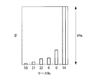
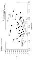
- FIG. 16 shows a bar graph comparing the values of the above six cases with respect to the objective function D ′.
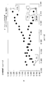
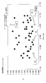
- FIGS. 17 to 20 show an objective function D ′, a design variable (1) and an objective function D ′. And a graph showing the correlation between the design variable (2), the objective function D 'and the design variable (3), and the objective function D' and the design variable (4).
- the central portion of the trailing edge line 14 of the plurality of blades 12 is as shown in FIG. 2 (A) or 3 (A) to 3 (C).
- the air flow on the negative pressure surface 15 side of the blade 12 is shown in the figure because it is configured to be concave 14A in the anti-air flow direction.
- a sharp flow with few abrupt changes in the spacing (no peeling) as in the limit flow line (the flow of the blade surface visualized in a linear manner). It can be a line.
- Case No. Case No. 0 in which the original shape or the evaluation was the lowest.
- the air flow on the negative pressure surface 15 side of the blade 12 has a turbulent spot X like the critical streamline shown in FIGS. 4 (D) and (E), and separation occurs in the air flow.
- case No. 2 shown in FIG. 2 (A) or FIGS. Case No. 59 where the optimum shape of 59 or the evaluation was ranked first to third. 31, Case No. 32 and Case No.
- Case No. Case No. 0 in which the original shape or the evaluation was the lowest.
- the high static pressure area Y generated on the pressure surface 16 of the blade 12 is generated in a relatively large area Y as shown in FIGS. 5 (D) and (E).
- the high static pressure region Y is not generated, or the region Y is made very small, and it is understood that the air flow does not decelerate and the fan efficiency is not reduced by the loss due to the deceleration .
- the air flow passing through the turbofan 7 is significantly affected by the bias toward the hub 10 side, and the pressure on the surface of the blade 12 also shows a distribution rising sharply toward the hub 10 side.
- the pressure (static pressure) in the vicinity of the trailing edge 14 of the blade 12 can be reduced, and the static pressure at the pressure surface 16 can be reduced, thereby improving the fan efficiency of the turbofan 7.
- the fan input can be reduced, and therefore, the noise and efficiency of the turbo fan 7 can be further reduced.
- trailing edge line 14 may be concaved 14A in the direction opposite to the air flow in the range of 25 to 75% of the central portion in the span direction, and the function and performance of the coupling portions 17 and 18 with respect to the hub 10 and the shroud 11
- the vanes 12 can be coupled to the hub 10 and the shroud 11 without affecting. Therefore, the air flow is not disturbed in the hub side coupling portion 17 and the shroud side coupling portion 18, and noise reduction and high efficiency can be achieved.
- the concave amount (indicated-) of the trailing edge line 14 of the blade 12 in the anti-air flow direction is in the range of -0.0142 D to -0.0153 D.
- the fan input which is the driving force of the turbo fan 7 can be reduced to a preferable range.
- the front edge line 13 of the blade 12 is span direction (rotational axis direction) In the direction of air flow with respect to the joints 17 and 18 with respect to the hub 10 and the shroud 11 in the range of 25 to 75% of the above, or in the direction of anti-air flow as shown in FIG. It is made convex 13B.
- the friction loss between the air flow and the surface of the vane 12 generally increases while the air flow direction length of the vane 12 Because the flow flowing from the upstream side of the blade is stably guided to the downstream side, the peak value of the static pressure on the surface of the blade 12 is suppressed to make it difficult to separate the flow. While being able to reduce input, fan noise can be reduced.
- the fan input which is the driving force of the turbo fan 7 can be reduced to a preferable range, and the turbo fan 7 has high efficiency and low efficiency. Noise can be improved.
- the central portion of the front edge line 13 of the blade 12 is shown in FIG. 2 (A) or 3 (A) to 3 (C) in the range of 25 to 75% of the span direction (rotational axis direction).
- the connecting portion 17 with the hub 10 and the shroud 11 is , 18 can be coupled to the hub 10 and the shroud 11 without affecting the function or performance. Therefore, the air flow is not disturbed in the hub side coupling portion 17 and the shroud side coupling portion 18, and noise reduction and high efficiency can be achieved.
- the concave amount (indicated by +) of the concave 13A in the air flow direction is in the range of 0.0091 D to 0.0153 D with respect to the fan outer diameter D, Because the amount of convexity (indicated-) of the convex 13B in the direction is -0.0438 D with respect to the fan outer diameter D, as shown in FIGS. 16 and 18, the fan input which is the driving force of the turbo fan 7 Can be reduced to a preferred range. By this, the noise reduction and the efficiency improvement of the turbo fan 7 can be achieved.
- connection portion (hub-side connection portion) 17 of the blade 12 to the hub 10 is smooth in the reverse rotation direction.
- a curved surface 17A is provided, and a coupling portion (shroud side coupling portion) 18 of the blade 12 to the shroud 11 is configured as a curved surface 18B that is smooth in the rotational direction.
- the connecting portion 17 of the blade 12 to the hub 10 has a smooth curved surface 17A in the opposite rotational direction, whereby the connecting portion 17 with the hub 10 is left-right asymmetrical, and air flow stagnation at the connecting portion 17 Can be suppressed, and the separation of the flow can be suppressed by the wing force BF, and the air flow can be smoothed, by forming the coupling portion of the blade 12 with the shroud 11 as the smooth curved surface 18B in the rotational direction. .
- FIG. 2 (B) and FIG. 4 (A) the disturbance of the air flow on the negative pressure surface 15 side of the blade 12 can be suppressed
- FIG. 2 (C) and FIG. 5 (A) As shown in the diagram, by reducing the high static pressure region on the pressure surface 16 side of the blade 12, it is possible to suppress the deceleration of the air flow (the loss of the driving force).
- the blade performance of the turbo fan 7 can be improved, and as shown in FIGS. 16, 19 and 20, the fan input which is the driving force of the turbo fan 7 can be reduced to achieve high efficiency and The disturbance of the flow can be suppressed and noise reduction can be achieved.
- the present invention is not limited to the invention according to the above-described embodiment, and appropriate modifications can be made without departing from the scope of the invention.
- the said embodiment demonstrated the example applied to the ceiling-embedded air conditioner 1 which arrange
- the present invention can be applied to an air conditioner or the like in which the temperature control air heat-exchanged through the heat exchanger is suctioned and blown out into the room from the upper and lower outlets in the centrifugal direction.
- the turbo fan 7 itself may be applied to devices other than the air conditioner.
- Air conditioner 7 Turbo fan (fan) 8 Heat Exchanger 10 Hub 11 Shroud 12 Blade 13 Front Edge (Front Edge Line) 13A concave 13B convex 14 rear edge (rear edge line) 14A concave 15 negative pressure surface 16 positive pressure surface 17 joint (hub side joint) 17A, 17B Curved surface 18 joint (shroud side joint) 18A, 18B Curved surface
Landscapes
- Engineering & Computer Science (AREA)
- Mechanical Engineering (AREA)
- General Engineering & Computer Science (AREA)
- Chemical & Material Sciences (AREA)
- Combustion & Propulsion (AREA)
- Structures Of Non-Positive Displacement Pumps (AREA)
- Air-Conditioning Room Units, And Self-Contained Units In General (AREA)
Priority Applications (2)
| Application Number | Priority Date | Filing Date | Title |
|---|---|---|---|
| EP16851050.1A EP3315786A4 (en) | 2015-10-02 | 2016-09-06 | Turbofan and air conditioner in which same is used |
| CN201680042586.5A CN107850081B (zh) | 2015-10-02 | 2016-09-06 | 涡轮风扇及使用了该涡轮风扇的空调 |
Applications Claiming Priority (2)
| Application Number | Priority Date | Filing Date | Title |
|---|---|---|---|
| JP2015196839A JP6642913B2 (ja) | 2015-10-02 | 2015-10-02 | ターボファンおよびそれを用いた空気調和機 |
| JP2015-196839 | 2015-10-02 |
Publications (1)
| Publication Number | Publication Date |
|---|---|
| WO2017056874A1 true WO2017056874A1 (ja) | 2017-04-06 |
Family
ID=58423422
Family Applications (1)
| Application Number | Title | Priority Date | Filing Date |
|---|---|---|---|
| PCT/JP2016/076156 Ceased WO2017056874A1 (ja) | 2015-10-02 | 2016-09-06 | ターボファンおよびそれを用いた空気調和機 |
Country Status (4)
| Country | Link |
|---|---|
| EP (1) | EP3315786A4 (enExample) |
| JP (1) | JP6642913B2 (enExample) |
| CN (1) | CN107850081B (enExample) |
| WO (1) | WO2017056874A1 (enExample) |
Families Citing this family (1)
| Publication number | Priority date | Publication date | Assignee | Title |
|---|---|---|---|---|
| CN116507808B (zh) | 2020-11-25 | 2025-04-22 | 三菱电机株式会社 | 涡轮风扇以及空调机 |
Citations (7)
| Publication number | Priority date | Publication date | Assignee | Title |
|---|---|---|---|---|
| JP2008144667A (ja) * | 2006-12-11 | 2008-06-26 | Daikin Ind Ltd | 送風機の羽根車 |
| WO2009069606A1 (ja) * | 2007-11-26 | 2009-06-04 | Daikin Industries, Ltd. | 遠心ファン |
| WO2009128299A1 (ja) * | 2008-04-18 | 2009-10-22 | 三菱電機株式会社 | ターボファンおよび空気調和機 |
| JP2011226448A (ja) * | 2010-04-23 | 2011-11-10 | Toshiba Carrier Corp | 遠心ファン及び空気調和機 |
| JP2013096378A (ja) * | 2011-11-04 | 2013-05-20 | Daikin Industries Ltd | 遠心送風機 |
| JP2013124575A (ja) * | 2011-12-14 | 2013-06-24 | Mitsubishi Electric Corp | ターボファン、空気調和装置 |
| WO2014061642A1 (ja) * | 2012-10-16 | 2014-04-24 | 三菱電機株式会社 | ターボファンおよび空気調和機 |
Family Cites Families (3)
| Publication number | Priority date | Publication date | Assignee | Title |
|---|---|---|---|---|
| DE1058200B (de) * | 1952-02-27 | 1959-05-27 | Bruno Eck Dr Ing | Blechschaufelrad fuer Radialgeblaese und meridianbeschleunigte Axialgeblaese |
| JP2009127541A (ja) * | 2007-11-26 | 2009-06-11 | Daikin Ind Ltd | 遠心ファン |
| JP4994421B2 (ja) * | 2009-05-08 | 2012-08-08 | 三菱電機株式会社 | 遠心ファン及び空気調和機 |
-
2015
- 2015-10-02 JP JP2015196839A patent/JP6642913B2/ja active Active
-
2016
- 2016-09-06 EP EP16851050.1A patent/EP3315786A4/en not_active Withdrawn
- 2016-09-06 CN CN201680042586.5A patent/CN107850081B/zh active Active
- 2016-09-06 WO PCT/JP2016/076156 patent/WO2017056874A1/ja not_active Ceased
Patent Citations (7)
| Publication number | Priority date | Publication date | Assignee | Title |
|---|---|---|---|---|
| JP2008144667A (ja) * | 2006-12-11 | 2008-06-26 | Daikin Ind Ltd | 送風機の羽根車 |
| WO2009069606A1 (ja) * | 2007-11-26 | 2009-06-04 | Daikin Industries, Ltd. | 遠心ファン |
| WO2009128299A1 (ja) * | 2008-04-18 | 2009-10-22 | 三菱電機株式会社 | ターボファンおよび空気調和機 |
| JP2011226448A (ja) * | 2010-04-23 | 2011-11-10 | Toshiba Carrier Corp | 遠心ファン及び空気調和機 |
| JP2013096378A (ja) * | 2011-11-04 | 2013-05-20 | Daikin Industries Ltd | 遠心送風機 |
| JP2013124575A (ja) * | 2011-12-14 | 2013-06-24 | Mitsubishi Electric Corp | ターボファン、空気調和装置 |
| WO2014061642A1 (ja) * | 2012-10-16 | 2014-04-24 | 三菱電機株式会社 | ターボファンおよび空気調和機 |
Non-Patent Citations (1)
| Title |
|---|
| See also references of EP3315786A4 * |
Also Published As
| Publication number | Publication date |
|---|---|
| CN107850081A (zh) | 2018-03-27 |
| CN107850081B (zh) | 2019-10-01 |
| JP2017067056A (ja) | 2017-04-06 |
| JP6642913B2 (ja) | 2020-02-12 |
| EP3315786A1 (en) | 2018-05-02 |
| EP3315786A4 (en) | 2018-07-04 |
Similar Documents
| Publication | Publication Date | Title |
|---|---|---|
| CN103597288B (zh) | 空气调节机 | |
| CN102422025B (zh) | 离心风扇及空调机 | |
| JP5263198B2 (ja) | 羽根車と送風機及びそれを用いた空気調和機 | |
| US9829004B2 (en) | Turbo fan and air conditioner | |
| JP5430754B2 (ja) | 軸流送風機 | |
| US10052931B2 (en) | Outdoor cooling unit in vehicle air-conditioning apparatus | |
| JP6463548B2 (ja) | 軸流送風機および室外機 | |
| JP6524331B2 (ja) | 送風機及びそれを用いた空気調和機 | |
| TR201901081T4 (tr) | Eksenel akımlı fan ve söz konusu eksenel akımlı fana sahip iklimlendirici. | |
| WO2014162552A1 (ja) | プロペラファン、送風装置及び室外機 | |
| JP6739656B2 (ja) | 羽根車、送風機、及び空気調和装置 | |
| JP5274278B2 (ja) | ターボファン及びターボファンを備えた空気調和装置 | |
| JP2016121580A (ja) | 遠心型送風機 | |
| JP6611676B2 (ja) | 送風機および冷凍サイクル装置の室外機 | |
| JP5984162B2 (ja) | プロペラファン、送風装置、および室外機 | |
| WO2017056874A1 (ja) | ターボファンおよびそれを用いた空気調和機 | |
| JP2016003641A (ja) | 遠心ファン | |
| CN108019847A (zh) | 出风罩及空调室外机 | |
| CN213360556U (zh) | 轴流风叶、轴流风机和空调器 | |
| WO2022191034A1 (ja) | プロペラファンおよび冷凍装置 | |
| JP2017067056A5 (enExample) | ||
| JP2012207612A (ja) | 軸流ファン | |
| WO2019021391A1 (ja) | 空気調和機 | |
| JP6429887B2 (ja) | 空気調和装置用室内機および空気調和装置 |
Legal Events
| Date | Code | Title | Description |
|---|---|---|---|
| 121 | Ep: the epo has been informed by wipo that ep was designated in this application |
Ref document number: 16851050 Country of ref document: EP Kind code of ref document: A1 |
|
| WWE | Wipo information: entry into national phase |
Ref document number: 2016851050 Country of ref document: EP |
|
| NENP | Non-entry into the national phase |
Ref country code: DE |