WO2017056869A1 - シリンダヘッドの冷却構造 - Google Patents
シリンダヘッドの冷却構造 Download PDFInfo
- Publication number
- WO2017056869A1 WO2017056869A1 PCT/JP2016/076099 JP2016076099W WO2017056869A1 WO 2017056869 A1 WO2017056869 A1 WO 2017056869A1 JP 2016076099 W JP2016076099 W JP 2016076099W WO 2017056869 A1 WO2017056869 A1 WO 2017056869A1
- Authority
- WO
- WIPO (PCT)
- Prior art keywords
- cooling water
- flow path
- water flow
- cylinder
- exhaust
- Prior art date
- Legal status (The legal status is an assumption and is not a legal conclusion. Google has not performed a legal analysis and makes no representation as to the accuracy of the status listed.)
- Ceased
Links
Images





Classifications
-
- F—MECHANICAL ENGINEERING; LIGHTING; HEATING; WEAPONS; BLASTING
- F01—MACHINES OR ENGINES IN GENERAL; ENGINE PLANTS IN GENERAL; STEAM ENGINES
- F01P—COOLING OF MACHINES OR ENGINES IN GENERAL; COOLING OF INTERNAL-COMBUSTION ENGINES
- F01P3/00—Liquid cooling
- F01P3/02—Arrangements for cooling cylinders or cylinder heads
-
- F—MECHANICAL ENGINEERING; LIGHTING; HEATING; WEAPONS; BLASTING
- F02—COMBUSTION ENGINES; HOT-GAS OR COMBUSTION-PRODUCT ENGINE PLANTS
- F02F—CYLINDERS, PISTONS OR CASINGS, FOR COMBUSTION ENGINES; ARRANGEMENTS OF SEALINGS IN COMBUSTION ENGINES
- F02F1/00—Cylinders; Cylinder heads
- F02F1/02—Cylinders; Cylinder heads having cooling means
- F02F1/10—Cylinders; Cylinder heads having cooling means for liquid cooling
-
- F—MECHANICAL ENGINEERING; LIGHTING; HEATING; WEAPONS; BLASTING
- F02—COMBUSTION ENGINES; HOT-GAS OR COMBUSTION-PRODUCT ENGINE PLANTS
- F02F—CYLINDERS, PISTONS OR CASINGS, FOR COMBUSTION ENGINES; ARRANGEMENTS OF SEALINGS IN COMBUSTION ENGINES
- F02F1/00—Cylinders; Cylinder heads
- F02F1/24—Cylinder heads
- F02F1/26—Cylinder heads having cooling means
- F02F1/36—Cylinder heads having cooling means for liquid cooling
-
- F—MECHANICAL ENGINEERING; LIGHTING; HEATING; WEAPONS; BLASTING
- F02—COMBUSTION ENGINES; HOT-GAS OR COMBUSTION-PRODUCT ENGINE PLANTS
- F02F—CYLINDERS, PISTONS OR CASINGS, FOR COMBUSTION ENGINES; ARRANGEMENTS OF SEALINGS IN COMBUSTION ENGINES
- F02F1/00—Cylinders; Cylinder heads
- F02F1/24—Cylinder heads
- F02F1/26—Cylinder heads having cooling means
- F02F1/36—Cylinder heads having cooling means for liquid cooling
- F02F1/38—Cylinder heads having cooling means for liquid cooling the cylinder heads being of overhead valve type
-
- F—MECHANICAL ENGINEERING; LIGHTING; HEATING; WEAPONS; BLASTING
- F02—COMBUSTION ENGINES; HOT-GAS OR COMBUSTION-PRODUCT ENGINE PLANTS
- F02F—CYLINDERS, PISTONS OR CASINGS, FOR COMBUSTION ENGINES; ARRANGEMENTS OF SEALINGS IN COMBUSTION ENGINES
- F02F1/00—Cylinders; Cylinder heads
- F02F1/24—Cylinder heads
- F02F1/26—Cylinder heads having cooling means
- F02F1/36—Cylinder heads having cooling means for liquid cooling
- F02F1/40—Cylinder heads having cooling means for liquid cooling cylinder heads with means for directing, guiding, or distributing liquid stream
Definitions
- This disclosure relates to a cylinder head cooling structure.
- a cooling structure is adopted in which a cooling water flow path is provided around the exhaust port and the injector boss to reduce the temperature of the cylinder head.
- Patent Document 1 in a cylinder head having a pair of exhaust ports for each cylinder, between the exhaust ports that are likely to become the highest temperature or between the exhaust ports so that cooling water is supplied near the injector boss.
- a cooling structure of a cylinder head provided with an extending exhaust port passage is disclosed.
- the cooling water supplied to the cylinder head is introduced from a water jacket in the cylinder block to a cooling water introducing portion formed below the exhaust port of the cylinder head.
- the cooling water introduction section is connected to a flow path between exhaust ports, a head bolt boss side flow path that flows in the vicinity of the head bolt boss section, and the like.
- an exhaust port upper flow path extending in the crankshaft direction (longitudinal direction) of the engine is formed above the flow path between exhaust ports, and an inter-cylinder flow extending between the cylinders in the short direction of the engine is formed between the cylinders. Roads are also formed.
- the cooling water introduced from the cylinder block to the cooling water introducing section is not supplied to the flow path between the exhaust ports at a high temperature, and the flow path between the cylinders and the flow path between the cylinders from the head bolt boss side flow path. There is a possibility that the cooling efficiency of the cylinder head will be lowered by flowing into the upper flow path of the exhaust port.
- the disclosed cooling structure is intended to improve the cooling efficiency of the cylinder head by effectively securing the cooling water flow rate from the cooling water introduction part of the cylinder head to the flow path between the exhaust ports.
- a plurality of cylinders are arranged in series in the longitudinal direction of the engine, and a pair of intake ports and a pair of exhaust ports are arranged in the longitudinal direction of the engine.
- a cooling structure for a cylinder head provided with a head bolt boss, and is provided below the exhaust port, and a cooling water introduction part for introducing cooling water supplied from the cylinder block side into the cylinder head;
- a boss side cooling water flow path that branches off from the cooling water introduction part and extends in the vicinity of the engine inside of the head bolt boss part, extends between the plurality of cylinders in the short direction of the engine, and an upstream end of the boss
- An inter-cylinder cooling water channel that merges with the side cooling water channel, a first inter-exhaust port cooling water channel that branches from the cooling water introduction part and extends between the pair of exhaust ports, It provided to the scan side cooling water channel, and a blocking wall for blocking flow of cooling water from the cooling water introduction section to the inter-cylinder coolant passage passing through said boss side cooling water flow path
- a plurality of cylinders are arranged in series in the longitudinal direction of the engine, and a pair of intake ports and a pair of exhaust ports are arranged in the longitudinal direction of the engine.
- a cooling structure for a cylinder head provided with a head bolt boss, and is provided below the exhaust port, and a cooling water introduction part for introducing cooling water supplied from the cylinder block side into the cylinder head;
- a boss side cooling water flow path that branches off from the cooling water introduction part and extends in the vicinity of the engine inside of the head bolt boss part, extends between the plurality of cylinders in the short direction of the engine, and an upstream end of the boss
- An inter-cylinder cooling water channel that merges with the side cooling water channel, a first inter-exhaust port cooling water channel that branches from the cooling water introduction part and extends between the pair of exhaust ports, Provided cylinder between the cooling water channel, and a first barrier wall that blocks the flow of cooling water to the inter-cylinder coolant passage passing through said boss side coolant passage from the cooling water in
- the cooling water is provided above the exhaust port in the longitudinal direction of the engine, and is provided in the cooling water flow path on the exhaust port where the downstream end of the boss side cooling water flow path joins, and in the inter-cylinder cooling water flow path.
- a second blocking wall that blocks the flow of the cooling water from the introduction part to the cooling water flow path on the exhaust port via the boss side cooling water flow path may be further provided.
- a third blocking wall that blocks a flow of cooling water from the water introduction part to the cooling water flow path between the second exhaust ports via the cooling water flow path between the first exhaust ports.
- an outer boss side cooling water flow path may be further provided which branches from the cooling water introduction part and extends outside the engine of the head bolt boss part in the longitudinal direction of the engine.
- a protrusion may be further provided that protrudes in the cooling water introduction portion with a predetermined protrusion amount and restricts the flow path of the cooling water from the cooling water introduction portion to the boss side cooling water flow passage.
- the cooling efficiency of the cylinder head can be improved by effectively securing the cooling water flow rate from the cooling water introduction part of the cylinder head to the flow path between the exhaust ports.
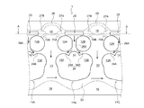
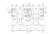
- FIG. 1A is a schematic bottom view of a part of the cooling structure of the cylinder head according to the first embodiment as viewed from below (cylinder block side).
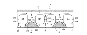
- 1B is a cross-sectional view taken along line AA in FIG. 1A.
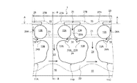
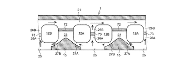
- FIG. 2A is a schematic bottom view of a part of the cylinder head cooling structure according to the second embodiment as viewed from below.
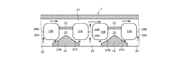
- 2B is a cross-sectional view taken along line AA in FIG. 2A.
- 2C is a cross-sectional view taken along line BB in FIG. 2A.
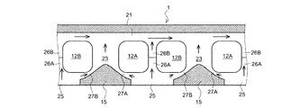
- FIG. 3A is a schematic bottom view of a part of the cylinder head cooling structure according to the third embodiment as viewed from below.
- 3B is a cross-sectional view taken along line AA in FIG. 3A.
- FIG. 3C is a cross-sectional view taken along line BB of FIG. 3A.
- FIG. 4A is a schematic bottom view of a part of a cylinder head cooling structure according to another embodiment as viewed from below (cylinder block side).
- 4B is a cross-sectional view taken along line AA in FIG. 4A.
- FIG. 5A is a schematic bottom view of a part of the cooling structure of the cylinder head according to another embodiment as viewed from below (cylinder block side).
- 5B is a cross-sectional view taken along line AA in FIG. 5A.
- FIG. 6A is a schematic bottom view of a part of the cooling structure of the cylinder head according to another embodiment viewed from below (cylinder block side). 6B is a cross-sectional view taken along line AA in FIG. 6A.
- FIGS. 1A and 1B are views for explaining a cooling structure of a cylinder head according to the first embodiment.
- the cooling structure of this embodiment is applied to a multi-cylinder in-line engine in which a plurality of cylinders are arranged in series in the longitudinal direction (crankshaft direction) of the engine.
- Each cylinder 11A to 11C of the cylinder head 1 has a pair of exhaust ports 12A and B that accommodate two exhaust valves (not shown) and a pair of intake ports 13A and B that respectively accommodate two intake valves (not shown). (Shown only in FIG. 1A) are opposed to each other at an interval. Further, an injector boss portion 14 (shown only in FIG. 1A) for installing an injector (not shown) is provided between the intake ports 13A and B facing the exhaust ports 12A and B.
- An exhaust side head bolt boss portion 15 for inserting a head bolt is provided between the cylinders 11A to 11C on the exhaust side of the cylinder head 1 at intervals. Further, an intake side head bolt boss portion 16 (shown only in FIG. 1A) for inserting a head bolt (not shown) is provided between the respective cylinders 11A to 11C on the intake side of the cylinder head 1 with an interval therebetween. Yes.
- an intake-side cooling water flow path 20 (shown only in FIG. 1A) is provided that extends in the vicinity of the intake ports 13 ⁇ / b> A and B along the longitudinal direction of the engine (hereinafter also referred to as the vertical direction). ing.
- a cooling water outlet (not shown) for returning the cooling water to a radiator (not shown) is provided at the downstream end of the intake-side cooling water channel 20.
- an exhaust port upper cooling water passage 21 (shown only in FIG. 1B) extending above the exhaust ports 12A and B along the longitudinal direction of the engine.
- the downstream side of the cooling water flow path 21 on the exhaust port is connected to the above-described cooling water outlet (not shown).
- an inter-cylinder cooling water passage 23 extending in the short direction of the engine is provided.
- the inter-cylinder cooling water passage 23 is formed so as to branch from inner head bolt boss side cooling water passages 27A and B, the details of which will be described later, and the downstream end thereof merges with the intake side cooling water passage 20.
- the inter-intake / exhaust port cooling water flow path 24 includes a first intake / exhaust port cooling water flow path 24A that flows between the intake port 13A and the exhaust port 12A, and a second intake path that flows between the intake port 13B and the exhaust port 12B. It is comprised by the cooling water flow path 24B between exhaust ports.
- a cooling water introduction part 25 for introducing cooling water into the cylinder head 1 from a water jacket of a cylinder block (not shown) is provided in the longitudinal direction of the engine. .
- each exhaust port 12A, B of the cylinder head 1 branches from the substantially longitudinal center of the cooling water introduction part 25 and extends between the exhaust ports 12A, B, and its downstream end is an intake / exhaust near the injector boss part 14.
- a first inter-exhaust-port cooling water passage 26 ⁇ / b> A joined to the inter-port cooling water passage 24 is provided.
- the second exhaust port extends upward from the first inter-exhaust-port cooling water flow channel 26A and extends downstream from the first inter-exhaust-port cooling water flow channel 26A.
- An inter-exhaust-port cooling water passage 26B (shown only in FIG. 1B) is provided.
- the outside head bolt boss side cooling water flow path 28 extending in the longitudinal direction of the engine is provided outside the engine of the exhaust side head bolt boss portion 15.
- the strength of the core used for casting is effectively ensured by connecting the cylinders by the outside head bolt boss side cooling water flow path 28.
- the blocking walls 70A, B are extended in the inner head bolt boss side cooling water passages 27A, B from the exhaust ports 12A, B toward the exhaust side head bolt boss portion 15, and the inner head bolt boss side cooling water passages 27A. , B and the inter-cylinder cooling water flow path 23 are divided. That is, the cooling water flow from the cooling water introduction part 25 to the inner head bolt boss side cooling water flow paths 27A and B ⁇ the inter-cylinder cooling water flow path 23 ⁇ the cooling water flow path 24 between the intake and exhaust ports is blocked by the blocking walls 70A and B. Thus, the cooling water is forced to flow from the cooling water introduction part 25 to the cooling water flow path 26A between the first exhaust ports.
- the junction between the inner head bolt boss side cooling water flow paths 27A and B and the inter-cylinder cooling water flow paths 23 is divided by the blocking walls 70A and B.
- the cooling water can easily flow from the cooling water introduction part 25 to the first inter-exhaust-port cooling water flow path 26A, and the cooling efficiency of the cylinder head 1 can be effectively improved.
- the outer head bolt boss side cooling water passage 28 extending in the longitudinal direction of the engine is provided outside the exhaust side head bolt boss portion 15, thereby effectively ensuring the strength of the core used for casting the cylinder head 1. be able to.
- FIGS. 2A to 2C are views for explaining a cooling structure of the cylinder head according to the second embodiment.
- symbol is attached
- the cooling structure of the second embodiment includes a first blocking wall 71 (shown in FIGS. 2A and 2C) and a second blocking wall 72 (shown in FIGS. 2B and 2C) provided in the inter-cylinder cooling water flow path 23. It is configured with.
- the first blocking wall 71 passes through the inter-cylinder cooling water passage 23 from the exhaust port 12B located on the upstream side in the longitudinal direction (left side in FIG. 2A) with respect to the inter-cylinder cooling water passage 23. 23 extends toward the exhaust port 12A located on the downstream side in the vertical direction (right side in FIG. 2A). In other words, the inter-cylinder cooling water flow path 23 that leads from the cooling water introducing portion 25 to the intake / exhaust port cooling water flow path 24 is divided by the first blocking wall 71.
- the second blocking wall 72 is located on the upstream side in the longitudinal direction with respect to the inter-cylinder cooling water flow channel 23 (on the left side in FIG. 2A) in the vicinity of the junction with the exhaust water cooling water flow channel 21 in the inter-cylinder cooling water flow channel 23. From the exhaust port 12B located, it extends toward the exhaust port 12A located on the downstream side in the longitudinal direction (the right side in FIG. 2A) with respect to the inter-cylinder coolant flow path 23 (see also FIG. 2B). That is, the second blocking wall 72 divides the inter-cylinder cooling water passage 23 that leads from the cooling water introduction portion 25 to the exhaust port cooling water passage 21.
- the first blocking wall 71 cools the cooling water introduction part 25 to the inter-cylinder cooling water passage 23 via the inter-cylinder cooling water passage 23.
- the flow of water is blocked, and further, the flow of the cooling water from the cooling water introduction part 25 to the cooling water flow path 21 on the exhaust port is blocked by the second blocking wall 72, so that the first exhaust from the cooling water introduction part 25.
- the amount of cooling water to the inter-port cooling water flow path 26A can be effectively increased, and the cooling efficiency of the cylinder head 1 can be reliably improved.
- FIGS. 3A to 3C are diagrams for explaining a cooling structure of the cylinder head according to the third embodiment.
- the second inter-exhaust port cooling water channel 26B is connected to the second inter-exhaust port cooling water channel 26B that connects the first inter-exhaust port cooling water channel 26A and the upper exhaust port cooling water channel 21.
- a horizontal third blocking wall 73 (shown in FIGS. 3B and 3C) that divides 26B and a vertical fourth blocking wall 74 (shown in FIGS. 3A and 3C) are provided.
- the second inter-exhaust port cooling water flow path 26B is divided by the third and fourth blocking walls 73 and 74, so that the first inter-exhaust port cooling water flow path 26A is connected to the intake / exhaust inter-port cooling water flow path 24.
- the flow of the cooling water is not hindered, and the cooling efficiency of the cylinder head 1 can be effectively improved.
- the first blocking wall 71 is extended to the upper surface side of the cylinder head 1 without providing the second blocking wall 72, so that the flow of the cooling water is completely completed. You may comprise so that it may interrupt
- a part of the first blocking wall 71 or the second blocking wall 72 is selectively omitted to change the flow of cooling water or to secure the strength of the core. May be.
- flow passage restricting protrusions 30A and B that protrude from the exhaust ports 12A and B by a predetermined protrusion amount are provided in the cooling water introduction part 25 so that the cooling head introduction part 25 and the inner head You may comprise so that the amount of cooling water to the bolt boss side cooling water flow path 27A, B can be adjusted or interrupted
- FIG. 6 shows an example in which the channel restricting protrusions 30A and 30B are provided in the second embodiment, but the present invention can also be applied to other embodiments such as the first embodiment and the third embodiment.
- outer head bolt boss side cooling water flow path 28 can be applied not only to the first embodiment but also to other embodiments such as the second embodiment and the third embodiment.
- the present invention has an effect of improving the cooling efficiency of the cylinder head and is useful for a cooling structure of the cylinder head.
Landscapes
- Engineering & Computer Science (AREA)
- Chemical & Material Sciences (AREA)
- Combustion & Propulsion (AREA)
- Mechanical Engineering (AREA)
- General Engineering & Computer Science (AREA)
- Cylinder Crankcases Of Internal Combustion Engines (AREA)
Abstract
複数の気筒11A~Cが直列に配置され、気筒11A~Cには吸気ポート13A,B及び排気ポート12A,Bが配置され、各気筒11A~C間の排気側にはヘッドボルトボス部15が設けられたシリンダヘッド冷却構造であって、排気ポート12A,Bの下方に設けられて冷却水をシリンダヘッド1内に導入する冷却水導入部25と、冷却水導入部25から分岐してヘッドボルトボス部15の近傍を延びるボス脇冷却水流路27A,Bと、複数の気筒11A~C間を延びると共に、その上流端がボス脇冷却水流路27A,Bに合流する気筒間冷却水流路23と、冷却水導入部25から分岐して排気ポート12A,B間を延びる排気ポート間冷却水流路26Aと、冷却水導入部25からボス脇冷却水流路27A,Bを経由した冷却水の流れを遮断する遮断壁70~74とを備える。
Description
本開示は、シリンダヘッドの冷却構造に関する。
一般的に、シリンダヘッドの触火面は高温になりやすいため、排気ポートやインジェクタボス部の周囲に冷却水流路を設けて、シリンダヘッドの温度低下を図る冷却構造が採用されている。
例えば、特許文献1には、各気筒に一対の排気ポートを備えたシリンダヘッドにおいて、最も高温になりやすい排気ポート間やインジェクタボス部近傍に冷却水が供給されるように、各排気ポート間を延びる排気ポート間流路を設けたシリンダヘッドの冷却構造が開示されている。
一般的に、シリンダヘッドに供給される冷却水は、シリンダブロック内のウォータジャケットからシリンダヘッドの排気ポート下方に形成された冷却水導入部に導入される。この冷却水導入部には、排気ポート間流路や、ヘッドボルトボス部の近傍を流れるヘッドボルトボス脇流路等が接続されている。また、排気ポート間流路の上方には、エンジンのクランク軸方向(長手方向)に延びる排気ポート上流路が形成され、各気筒間には、気筒間をエンジンの短手方向に延びる気筒間流路等も形成されている。
このような流路構造においては、シリンダブロックから冷却水導入部に導入された冷却水が、温度の高い排気ポート間流路に供給されずに、ヘッドボルトボス脇流路から気筒間流路や排気ポート上流路に流れてしまい、シリンダヘッドの冷却効率を低下させてしまう可能性がある。
開示の冷却構造は、シリンダヘッドの冷却水導入部から排気ポート間流路への冷却水流量を効果的に確保することで、シリンダヘッドの冷却効率を向上することを目的とする。
開示の冷却構造は、エンジンの長手方向に複数の気筒が直列に配置され、前記気筒には一対の吸気ポート及び一対の排気ポートが前記エンジンの長手方向にそれぞれ配置され、各気筒間の排気側にはヘッドボルトボス部が設けられたシリンダヘッドの冷却構造であって、前記排気ポートの下方に設けられて、シリンダブロック側から供給される冷却水をシリンダヘッド内に導入する冷却水導入部と、前記冷却水導入部から分岐して前記ヘッドボルトボス部のエンジン内側近傍を延びるボス脇冷却水流路と、前記複数の気筒間を前記エンジンの短手方向に延びると共に、その上流端が前記ボス脇冷却水流路に合流する気筒間冷却水流路と、前記冷却水導入部から分岐して前記一対の排気ポート間を延びる第1排気ポート間冷却水流路と、前記ボス脇冷却水流路内に設けられて、前記冷却水導入部から前記ボス脇冷却水流路を経由した前記気筒間冷却水流路への冷却水の流れを遮断する遮断壁と、を備える。
開示の冷却構造は、エンジンの長手方向に複数の気筒が直列に配置され、前記気筒には一対の吸気ポート及び一対の排気ポートが前記エンジンの長手方向にそれぞれ配置され、各気筒間の排気側にはヘッドボルトボス部が設けられたシリンダヘッドの冷却構造であって、前記排気ポートの下方に設けられて、シリンダブロック側から供給される冷却水をシリンダヘッド内に導入する冷却水導入部と、前記冷却水導入部から分岐して前記ヘッドボルトボス部のエンジン内側近傍を延びるボス脇冷却水流路と、前記複数の気筒間を前記エンジンの短手方向に延びると共に、その上流端が前記ボス脇冷却水流路に合流する気筒間冷却水流路と、前記冷却水導入部から分岐して前記一対の排気ポート間を延びる第1排気ポート間冷却水流路と、前記気筒間冷却水流路内に設けられて、前記冷却水導入部から前記ボス脇冷却水流路を経由した前記気筒間冷却水流路への冷却水の流れを遮断する第1遮断壁と、を備える。
前記排気ポートの上方を前記エンジンの長手方向に延びると共に、前記ボス脇冷却水流路の下流端が合流する排気ポート上冷却水流路と、前記気筒間冷却水流路内に設けられて、前記冷却水導入部から前記ボス脇冷却水流路を経由した前記排気ポート上冷却水流路への冷却水の流れを遮断する第2遮断壁と、をさらに備えてもよい。
前記排気ポートと前記吸気ポートとの間を前記エンジンの長手方向に延びると共に、前記第1排気ポート間冷却水流路の下流端が合流する吸排気ポート間流路と、前記第1排気ポート間冷却水流路から上方に分岐すると共に、その下流端が前記排気ポート上冷却水流路に合流する第2排気ポート間冷却水流路と、前記第2排気ポート間冷却水流路内に設けられて、前記冷却水導入部から前記第1排気ポート間冷却水流路を経由した前記第2排気ポート間冷却水流路への冷却水の流れを遮断する第3遮断壁と、をさらに備えてもよい。
前記冷却水導入部から分岐して前記ヘッドボルトボス部のエンジン外側を前記エンジンの長手方向に延びる外側ボス脇冷却水流路をさらに備えてもよい。
前記冷却水導入部内に所定の突出量で突出して設けられて、前記冷却水導入部から前記ボス脇冷却水流路への冷却水の流路を絞る突起部をさらに備えてもよい。
開示の冷却構造によれば、シリンダヘッドの冷却水導入部から排気ポート間流路への冷却水流量を効果的に確保することで、シリンダヘッドの冷却効率を向上することができる。
以下、添付図面に基づいて、本開示の各実施形態に係るシリンダヘッドの冷却構造を説明する。
[第一実施形態]
図1A,図1Bは、第一実施形態に係るシリンダヘッドの冷却構造を説明する図である。本実施形態の冷却構造は、複数の気筒がエンジンの長手方向(クランク軸方向)に直列に配置された多気筒直列エンジンに適用される。
図1A,図1Bは、第一実施形態に係るシリンダヘッドの冷却構造を説明する図である。本実施形態の冷却構造は、複数の気筒がエンジンの長手方向(クランク軸方向)に直列に配置された多気筒直列エンジンに適用される。
シリンダヘッド1の各気筒11A~Cには、図示しない二本の排気バルブをそれぞれ収容した一対の排気ポート12A,B及び、図示しない二本の吸気バルブをそれぞれ収容した一対の吸気ポート13A,B(図1Aにのみ示す)がそれぞれ間隔を隔てて対向配置されている。また、各排気ポート12A,B間に臨む吸気ポート13A,B間には、図示しないインジェクタを設置するためのインジェクタボス部14(図1Aにのみ示す)が設けられている。
シリンダヘッド1の排気側の各気筒11A~C間には、図示しないヘッドボルトを挿入するための排気側ヘッドボルトボス部15がそれぞれ間隔を隔てて設けられている。また、シリンダヘッド1の吸気側の各気筒11A~C間には、図示しないヘッドボルトを挿入するための吸気側ヘッドボルトボス部16(図1Aにのみ示す)がそれぞれ間隔を隔てて設けられている。
シリンダヘッド1の吸気側には、各吸気ポート13A,Bの近傍をエンジンの長手方向(以下、縦方向ともいう)に沿って延びる吸気側冷却水流路20(図1Aにのみ示す)が設けられている。この吸気側冷却水流路20の下流端には、ラジエータ(不図示)に冷却水を戻すための冷却水出口部(不図示)が設けられている。
シリンダヘッド1の排気側には、排気ポート12A,Bの上方をエンジンの長手方向に沿って延びる排気ポート上冷却水流路21(図1Bにのみ示す)が設けられている。この排気ポート上冷却水流路21の下流側は、上述した冷却水出口部(不図示)に接続されている。
シリンダヘッド1の各気筒11A~C間には、エンジンの短手方向に延びる気筒間冷却水流路23が設けられている。この気筒間冷却水流路23は、詳細を後述する内側ヘッドボルトボス脇冷却水流路27A,Bから分岐すると共に、その下流端が吸気側冷却水流路20に合流するように形成されている。
シリンダヘッド1の排気ポート12A,Bと吸気ポート13A,Bとの間には、エンジンの略中央を長手方向に延びて気筒間冷却水流路23に合流する吸排気ポート間冷却水流路24(図1Aにのみ示す)が設けられている。この吸排気ポート間冷却水流路24は、吸気ポート13Aと排気ポート12Aとの間を流れる第1吸排気ポート間冷却水流路24A及び、吸気ポート13Bと排気ポート12Bとの間を流れる第2吸排気ポート間冷却水流路24Bで構成されている。
シリンダヘッド1の各排気ポート12A,Bの下方には、図示しないシリンダブロックのウォータジャケットからシリンダヘッド1内に冷却水を導入するための冷却水導入部25がエンジンの長手方向に設けられている。
シリンダヘッド1の各排気ポート12A,B間には、冷却水導入部25の長手方向略中央から分岐して排気ポート12A,B間を延びると共に、その下流端をインジェクタボス部14近傍の吸排気ポート間冷却水流路24に合流させた第1排気ポート間冷却水流路26Aが設けられている。また、第1排気ポート間冷却水流路26Aの上方には、第1排気ポート間冷却水流路26Aから上方に向かって延びると共に、その下流端を排気ポート上冷却水流路21に合流させた第2排気ポート間冷却水流路26B(図1Bにのみ示す)が設けられている。
シリンダヘッド1の各排気ポート12A,Bと排気側ヘッドボルトボス部15との間には、冷却水導入部25の長手方向両端から分岐して、排気側ヘッドボルトボス部15のエンジン内側を延びると共に、気筒間冷却水流路23及び、排気ポート上冷却水流路21に合流する一対の内側ヘッドボルトボス脇冷却水流路27A,Bが設けられている。この内側ヘッドボルトボス脇冷却水流路27A,Bには、詳細を後述する遮断壁70A,Bがそれぞれ設けられている。
排気側ヘッドボルトボス部15のエンジン外側には、エンジンの長手方向に延びる外側ヘッドボルトボス脇冷却水流路28が設けられている。このように、外側ヘッドボルトボス脇冷却水流路28によって各気筒間を繋ぐことで、鋳造に用いる中子の強度が効果的に確保されるようになっている。
遮断壁70A,Bは、内側ヘッドボルトボス脇冷却水流路27A,B内を排気ポート12A,Bから排気側ヘッドボルトボス部15に向かって延設されて、内側ヘッドボルトボス脇冷却水流路27A,Bと気筒間冷却水流路23との合流部を分断する。すなわち、冷却水導入部25→内側ヘッドボルトボス脇冷却水流路27A,B→気筒間冷却水流路23→吸排気ポート間冷却水流路24への冷却水の流れが遮断壁70A,Bによって遮断されることで、冷却水が冷却水導入部25から第1排気ポート間冷却水流路26Aに強制的に流されるように構成されている。
以上詳述したように、第一実施形態の冷却構造によれば、内側ヘッドボルトボス脇冷却水流路27A,B内の気筒間冷却水流路23との合流部を遮閉壁70A,Bによって分断したことで、冷却水が冷却水導入部25から第1排気ポート間冷却水流路26Aに流れやすい状態になり、シリンダヘッド1の冷却効率を効果的に向上することができる。また、排気側ヘッドボルトボス部15の外側にエンジンの長手方向に延びる外側ヘッドボルトボス脇冷却水流路28を設けたことで、シリンダヘッド1の鋳造に用いる中子の強度を効果的に確保することができる。
[第二実施形態]
図2A~図2Cは、第二実施形態に係るシリンダヘッドの冷却構造を説明する図である。第一実施形態と同一の構成には同一の符号を付してあり、それらの名称及び機能も同じである。したがって、それらについての詳細な説明は省略する。
図2A~図2Cは、第二実施形態に係るシリンダヘッドの冷却構造を説明する図である。第一実施形態と同一の構成には同一の符号を付してあり、それらの名称及び機能も同じである。したがって、それらについての詳細な説明は省略する。
第二実施形態の冷却構造は、気筒間冷却水流路23内に設けられた第1遮断壁71(図2A、図2Cに示す)及び、第2遮断壁72(図2B、図2Cに示す)を備えて構成されている。
第1遮断壁71は、気筒間冷却水流路23内を、当該気筒間冷却水流路23に対して縦方向上流側(図2A中左側)に位置する排気ポート12Bから、当該気筒間冷却水流路23に対して縦方向下流側(図2A中右側)に位置する排気ポート12Aに向かって延設されている。すなわち、第1遮断壁71によって、冷却水導入部25から吸排気ポート間冷却水流路24に通じる気筒間冷却水流路23が分断されるようになっている。
第2遮断壁72は、気筒間冷却水流路23内の排気ポート上冷却水流路21との合流部近傍を、当該気筒間冷却水流路23に対して縦方向上流側(図2A中左側)に位置する排気ポート12Bから、当該気筒間冷却水流路23に対して縦方向下流側(図2A中右側)に位置する排気ポート12Aに向かって延設されている(図2Bも参照)。すなわち、第2遮断壁72によって、冷却水導入部25から排気ポート上冷却水流路21に通じる気筒間冷却水流路23が分断されるようになっている。
以上詳述したように、第二実施形態の冷却構造によれば、第1遮断壁71によって冷却水導入部25から気筒間冷却水流路23を経由した吸排気ポート間冷却水流路24への冷却水の流れが遮断され、さらに、第2遮断壁72によって冷却水導入部25から排気ポート上冷却水流路21への冷却水の流れが遮断されることで、冷却水導入部25から第1排気ポート間冷却水流路26Aへの冷却水量を効果的に増加されるようになり、シリンダヘッド1の冷却効率を確実に向上することができる。
[第三実施形態]
図3A~図3Cは、第三実施形態に係るシリンダヘッドの冷却構造を説明する図である。第三実施形態の冷却構造は、第1排気ポート間冷却水流路26Aと排気ポート上冷却水流路21とを接続する第2排気ポート間冷却水流路26Bに、当該第2排気ポート間冷却水流路26Bを分断する横方向の第3遮断壁73(図3B、図3Cに示す)と、上下方向の第4遮断壁74(図3A、図3Cに示す)とを備えて構成されている。このように、第2排気ポート間冷却水流路26Bを第3及び第4遮断壁73,74によって分断することで、第1排気ポート間冷却水流路26Aから吸排気ポート間冷却水流路24への冷却水の流れが阻害されなくなり、シリンダヘッド1の冷却効率を効果的に向上することができる。
図3A~図3Cは、第三実施形態に係るシリンダヘッドの冷却構造を説明する図である。第三実施形態の冷却構造は、第1排気ポート間冷却水流路26Aと排気ポート上冷却水流路21とを接続する第2排気ポート間冷却水流路26Bに、当該第2排気ポート間冷却水流路26Bを分断する横方向の第3遮断壁73(図3B、図3Cに示す)と、上下方向の第4遮断壁74(図3A、図3Cに示す)とを備えて構成されている。このように、第2排気ポート間冷却水流路26Bを第3及び第4遮断壁73,74によって分断することで、第1排気ポート間冷却水流路26Aから吸排気ポート間冷却水流路24への冷却水の流れが阻害されなくなり、シリンダヘッド1の冷却効率を効果的に向上することができる。
なお、本発明は、上述の各実施形態に限定されるものではなく、本発明の趣旨を逸脱しない範囲で、適宜変形して実施することが可能である。
例えば、図4に示すように、第二実施形態において、第2遮断壁72を設けることなく、第1遮断壁71をシリンダヘッド1の上面側まで延設することで、冷却水の流れを完全に遮断するように構成してもよい。また、図5に示すように、第1遮断壁71又は第2遮断壁72の一部を選択的に省略して、冷却水の流れを変えたり、中子の強度を確保するように構成してもよい。
また、図6に示すように、冷却水導入部25内に排気ポート12A,B側から所定の突出量で突出する流路絞り突起部30A,Bを設けて、冷却水導入部25から内側ヘッドボルトボス脇冷却水流路27A,Bへの冷却水量を調整或は遮断できるように構成してもよい。なお、図6は、第二実施形態に流路絞り突起部30A,Bを設けた例を示すが、第一実施形態や第三実施形態等、他の実施形態にも適用することができる。
また、外側ヘッドボルトボス脇冷却水流路28は、第一実施形態のみならず、第二実施形態や第三実施形態等、他の実施形態にも適用することができる。
本出願は、2015年9月30日付で出願された日本国特許出願(特願2015-194307)に基づくものであり、その内容はここに参照として取り込まれる。
本発明は、シリンダヘッドの冷却効率を向上するという効果を有し、シリンダヘッドの冷却構造等に有用である。
1 シリンダヘッド
11A~C 気筒
12A,B 排気ポート
13A,B 吸気ポート
14 インジェクタボス部
15 排気側ヘッドボルトボス部
16 吸気側ヘッドボルトボス部
20 吸気側冷却水流路
21 排気ポート上冷却水流路
23 気筒間冷却水流路
24 吸排気ポート間冷却水流路
25 冷却水導入部
26A 第1排気ポート間冷却水流路
26B 第2排気ポート間冷却水流路
27A,B 内側ヘッドボルトボス脇冷却水流路
28 外側ヘッドボルトボス脇冷却水流路
70 遮断壁
71 第1遮断壁
72 第2遮断壁
73 第3遮断壁
74 第4遮断壁
11A~C 気筒
12A,B 排気ポート
13A,B 吸気ポート
14 インジェクタボス部
15 排気側ヘッドボルトボス部
16 吸気側ヘッドボルトボス部
20 吸気側冷却水流路
21 排気ポート上冷却水流路
23 気筒間冷却水流路
24 吸排気ポート間冷却水流路
25 冷却水導入部
26A 第1排気ポート間冷却水流路
26B 第2排気ポート間冷却水流路
27A,B 内側ヘッドボルトボス脇冷却水流路
28 外側ヘッドボルトボス脇冷却水流路
70 遮断壁
71 第1遮断壁
72 第2遮断壁
73 第3遮断壁
74 第4遮断壁
Claims (6)
- エンジンの長手方向に複数の気筒が直列に配置され、前記気筒には一対の吸気ポート及び一対の排気ポートが前記エンジンの長手方向にそれぞれ配置され、各気筒間の排気側にはヘッドボルトボス部が設けられたシリンダヘッドの冷却構造であって、
前記排気ポートの下方に設けられて、シリンダブロック側から供給される冷却水をシリンダヘッド内に導入する冷却水導入部と、
前記冷却水導入部から分岐して前記ヘッドボルトボス部のエンジン内側近傍を延びるボス脇冷却水流路と、
前記複数の気筒間を前記エンジンの短手方向に延びると共に、その上流端が前記ボス脇冷却水流路に合流する気筒間冷却水流路と、
前記冷却水導入部から分岐して前記一対の排気ポート間を延びる第1排気ポート間冷却水流路と、
前記ボス脇冷却水流路内に設けられて、前記冷却水導入部から前記ボス脇冷却水流路を経由した前記気筒間冷却水流路への冷却水の流れを遮断する遮断壁と、を備える
シリンダヘッドの冷却構造。 - エンジンの長手方向に複数の気筒が直列に配置され、前記気筒には一対の吸気ポート及び一対の排気ポートが前記エンジンの長手方向にそれぞれ配置され、各気筒間の排気側にはヘッドボルトボス部が設けられたシリンダヘッドの冷却構造であって、
前記排気ポートの下方に設けられて、シリンダブロック側から供給される冷却水をシリンダヘッド内に導入する冷却水導入部と、
前記冷却水導入部から分岐して前記ヘッドボルトボス部のエンジン内側近傍を延びるボス脇冷却水流路と、
前記複数の気筒間を前記エンジンの短手方向に延びると共に、その上流端が前記ボス脇冷却水流路に合流する気筒間冷却水流路と、
前記冷却水導入部から分岐して前記一対の排気ポート間を延びる第1排気ポート間冷却水流路と、
前記気筒間冷却水流路内に設けられて、前記冷却水導入部から前記ボス脇冷却水流路を経由した前記気筒間冷却水流路への冷却水の流れを遮断する第1遮断壁と、を備える
シリンダヘッドの冷却構造。 - 前記排気ポートの上方を前記エンジンの長手方向に延びると共に、前記ボス脇冷却水流路の下流端が合流する排気ポート上冷却水流路と、
前記気筒間冷却水流路内に設けられて、前記冷却水導入部から前記ボス脇冷却水流路を経由した前記排気ポート上冷却水流路への冷却水の流れを遮断する第2遮断壁と、をさらに備える
請求項2に記載のシリンダヘッドの冷却構造。 - 前記排気ポートと前記吸気ポートとの間を前記エンジンの長手方向に延びると共に、前記第1排気ポート間冷却水流路の下流端が合流する吸排気ポート間流路と、
前記第1排気ポート間冷却水流路から上方に分岐すると共に、その下流端が前記排気ポート上冷却水流路に合流する第2排気ポート間冷却水流路と、
前記第2排気ポート間冷却水流路内に設けられて、前記冷却水導入部から前記第1排気ポート間冷却水流路を経由した前記第2排気ポート間冷却水流路への冷却水の流れを遮断する第3遮断壁と、をさらに備える
請求項2又は3に記載のシリンダヘッドの冷却構造。 - 前記冷却水導入部から分岐して前記ヘッドボルトボス部のエンジン外側を前記エンジンの長手方向に延びる外側ボス脇冷却水流路をさらに備える
請求項1から4の何れか一項に記載のシリンダヘッドの冷却構造。 - 前記冷却水導入部内に所定の突出量で突出して設けられて、前記冷却水導入部から前記ボス脇冷却水流路への冷却水の流路を絞る突起部をさらに備える
請求項1から5の何れか一項に記載のシリンダヘッドの冷却構造。
Priority Applications (1)
| Application Number | Priority Date | Filing Date | Title |
|---|---|---|---|
| CN201680055975.1A CN108138691B (zh) | 2015-09-30 | 2016-09-06 | 汽缸盖的冷却构造 |
Applications Claiming Priority (2)
| Application Number | Priority Date | Filing Date | Title |
|---|---|---|---|
| JP2015194307A JP6665472B2 (ja) | 2015-09-30 | 2015-09-30 | シリンダヘッドの冷却構造 |
| JP2015-194307 | 2015-09-30 |
Publications (1)
| Publication Number | Publication Date |
|---|---|
| WO2017056869A1 true WO2017056869A1 (ja) | 2017-04-06 |
Family
ID=58423270
Family Applications (1)
| Application Number | Title | Priority Date | Filing Date |
|---|---|---|---|
| PCT/JP2016/076099 Ceased WO2017056869A1 (ja) | 2015-09-30 | 2016-09-06 | シリンダヘッドの冷却構造 |
Country Status (3)
| Country | Link |
|---|---|
| JP (1) | JP6665472B2 (ja) |
| CN (1) | CN108138691B (ja) |
| WO (1) | WO2017056869A1 (ja) |
Families Citing this family (1)
| Publication number | Priority date | Publication date | Assignee | Title |
|---|---|---|---|---|
| JP7015209B2 (ja) * | 2018-05-23 | 2022-02-02 | カワサキモータース株式会社 | 鞍乗車両用エンジンの冷却水流路構造 |
Citations (4)
| Publication number | Priority date | Publication date | Assignee | Title |
|---|---|---|---|---|
| JPH0921348A (ja) * | 1995-07-06 | 1997-01-21 | Nissan Motor Co Ltd | 水冷式内燃機関のシリンダヘッド |
| DE19608576C1 (de) * | 1996-03-06 | 1997-06-19 | Daimler Benz Ag | Flüssigkeitsgekühlter Zylinderkopf für eine mehrzylindrige Brennkraftmaschine |
| JP2008190497A (ja) * | 2007-02-07 | 2008-08-21 | Toyota Motor Corp | 多気筒エンジンの冷却装置 |
| US20090260588A1 (en) * | 2008-04-21 | 2009-10-22 | Hyundai Motor Company | Cylinder head |
Family Cites Families (1)
| Publication number | Priority date | Publication date | Assignee | Title |
|---|---|---|---|---|
| JP4112391B2 (ja) * | 2003-02-06 | 2008-07-02 | 本田技研工業株式会社 | 内燃機関のシリンダヘッド |
-
2015
- 2015-09-30 JP JP2015194307A patent/JP6665472B2/ja active Active
-
2016
- 2016-09-06 WO PCT/JP2016/076099 patent/WO2017056869A1/ja not_active Ceased
- 2016-09-06 CN CN201680055975.1A patent/CN108138691B/zh active Active
Patent Citations (4)
| Publication number | Priority date | Publication date | Assignee | Title |
|---|---|---|---|---|
| JPH0921348A (ja) * | 1995-07-06 | 1997-01-21 | Nissan Motor Co Ltd | 水冷式内燃機関のシリンダヘッド |
| DE19608576C1 (de) * | 1996-03-06 | 1997-06-19 | Daimler Benz Ag | Flüssigkeitsgekühlter Zylinderkopf für eine mehrzylindrige Brennkraftmaschine |
| JP2008190497A (ja) * | 2007-02-07 | 2008-08-21 | Toyota Motor Corp | 多気筒エンジンの冷却装置 |
| US20090260588A1 (en) * | 2008-04-21 | 2009-10-22 | Hyundai Motor Company | Cylinder head |
Also Published As
| Publication number | Publication date |
|---|---|
| JP6665472B2 (ja) | 2020-03-13 |
| JP2017066997A (ja) | 2017-04-06 |
| CN108138691B (zh) | 2020-07-07 |
| CN108138691A (zh) | 2018-06-08 |
Similar Documents
| Publication | Publication Date | Title |
|---|---|---|
| JP5631859B2 (ja) | 一体化した排気マニホールドおよび重ね合わされ互いに間隔をあけたマニホールド部分に合流する排気導管のサブグループを有する内部燃焼エンジン用シリンダヘッド | |
| US8671904B2 (en) | Cylinder head for an internal combustion engine, with integrated exhaust manifold and subgroups of exhaust conduits merging into manifold portions which are superimposed and spaced apart from each other | |
| JP4438643B2 (ja) | エンジンのシリンダヘッド構造 | |
| US20160186641A1 (en) | Cooling structure of internal combustion engine | |
| CN108252816B (zh) | 水冷发动机的冷却结构 | |
| CN110366636B (zh) | 用于内燃机的气缸盖 | |
| JP2014139421A5 (ja) | ||
| JP5278299B2 (ja) | シリンダヘッドの冷却構造 | |
| JP2011202578A (ja) | シリンダヘッドのウォータジャケット構造 | |
| CN105814300A (zh) | 发动机的气缸盖 | |
| JP2016173107A (ja) | 冷却チャネルを有する内燃機関用シリンダヘッド | |
| CN107208568A (zh) | 气缸盖 | |
| JP2007278065A (ja) | 排気マニホールド一体型シリンダヘッドの冷却構造 | |
| WO2017030075A1 (ja) | シリンダヘッドの冷却構造 | |
| JP2015059492A (ja) | シリンダヘッド | |
| WO2017056869A1 (ja) | シリンダヘッドの冷却構造 | |
| JP6052135B2 (ja) | エンジンの冷却装置 | |
| JP2018080679A (ja) | シリンダヘッド | |
| JP6696125B2 (ja) | シリンダヘッドの冷却構造 | |
| JP2003184643A (ja) | シリンダヘッドの冷却水通路構造 | |
| JP2017193971A (ja) | シリンダヘッド | |
| JP6728952B2 (ja) | 内燃機関のシリンダヘッド | |
| JP2020101090A (ja) | シリンダヘッド | |
| JP2008231934A (ja) | 頭上四弁式多気筒内燃機関におけるシリンダヘッド | |
| CN206522194U (zh) | 进气道的冷却及隔热结构 |
Legal Events
| Date | Code | Title | Description |
|---|---|---|---|
| 121 | Ep: the epo has been informed by wipo that ep was designated in this application |
Ref document number: 16851045 Country of ref document: EP Kind code of ref document: A1 |
|
| NENP | Non-entry into the national phase |
Ref country code: DE |
|
| 122 | Ep: pct application non-entry in european phase |
Ref document number: 16851045 Country of ref document: EP Kind code of ref document: A1 |