WO2017056840A1 - 自動変速機の制御装置 - Google Patents
自動変速機の制御装置 Download PDFInfo
- Publication number
- WO2017056840A1 WO2017056840A1 PCT/JP2016/075592 JP2016075592W WO2017056840A1 WO 2017056840 A1 WO2017056840 A1 WO 2017056840A1 JP 2016075592 W JP2016075592 W JP 2016075592W WO 2017056840 A1 WO2017056840 A1 WO 2017056840A1
- Authority
- WO
- WIPO (PCT)
- Prior art keywords
- gear
- speed
- shift
- pressure
- automatic transmission
- Prior art date
- Legal status (The legal status is an assumption and is not a legal conclusion. Google has not performed a legal analysis and makes no representation as to the accuracy of the status listed.)
- Ceased
Links
Images





Classifications
-
- F—MECHANICAL ENGINEERING; LIGHTING; HEATING; WEAPONS; BLASTING
- F16—ENGINEERING ELEMENTS AND UNITS; GENERAL MEASURES FOR PRODUCING AND MAINTAINING EFFECTIVE FUNCTIONING OF MACHINES OR INSTALLATIONS; THERMAL INSULATION IN GENERAL
- F16H—GEARING
- F16H61/00—Control functions within control units of change-speed- or reversing-gearings for conveying rotary motion ; Control of exclusively fluid gearing, friction gearing, gearings with endless flexible members or other particular types of gearing
- F16H61/04—Smoothing ratio shift
- F16H61/08—Timing control
-
- F—MECHANICAL ENGINEERING; LIGHTING; HEATING; WEAPONS; BLASTING
- F16—ENGINEERING ELEMENTS AND UNITS; GENERAL MEASURES FOR PRODUCING AND MAINTAINING EFFECTIVE FUNCTIONING OF MACHINES OR INSTALLATIONS; THERMAL INSULATION IN GENERAL
- F16H—GEARING
- F16H61/00—Control functions within control units of change-speed- or reversing-gearings for conveying rotary motion ; Control of exclusively fluid gearing, friction gearing, gearings with endless flexible members or other particular types of gearing
- F16H61/68—Control functions within control units of change-speed- or reversing-gearings for conveying rotary motion ; Control of exclusively fluid gearing, friction gearing, gearings with endless flexible members or other particular types of gearing specially adapted for stepped gearings
Definitions
- the present invention relates to a control device for an automatic transmission.
- Patent Document 1 The technology described in Patent Document 1 is known as an automatic transmission control device.
- the loss stroke of the piston is compensated for the frictional engagement element engaged at the 3rd speed and 2nd speed.
- Simultaneous preparation hydraulic pressure (hereinafter referred to as “precharge pressure”) is simultaneously applied, thereby ensuring responsiveness when a request to another gear stage is made.
- the present invention has been made paying attention to the above problems, and an object of the present invention is to provide a control device for an automatic transmission that can suppress a shift shock and a decrease in shift response.
- the shift is performed before the target shift stage is determined.
- the frictional engagement elements that are engaged at a certain speed are precharged, and then the frictional engagement elements that are engaged at other speeds that are likely to be shifted are precharged.
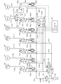
- FIG. 1 is a skeleton diagram showing a configuration of an automatic transmission that achieves an FR type forward seventh speed reverse first speed of Example 1.
- FIG. FIG. 3 is a circuit diagram illustrating a hydraulic circuit of the control valve unit according to the first embodiment. It is a figure which shows the fastening operation
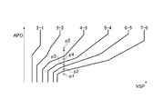
- FIG. 3 is a diagram illustrating an operation table of solenoid valves SOL1 to SOL7 at each gear position according to the first embodiment. It is a figure which shows a downshift line among the shift maps of Example 1.
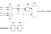
- FIG. FIG. 3 is a control block diagram illustrating precharge control according to the first embodiment. 3 is a flowchart illustrating a precharge control process according to the first embodiment.
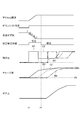
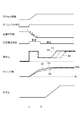
- FIG. 6 is a time chart when a sufficient oil pump discharge flow rate is ensured when downshifting from the seventh speed in the precharge control process of the first embodiment.
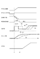
- 7 is a time chart when the oil pump discharge flow rate is Qc ⁇ Qb ⁇ Qa when downshifting from the seventh speed in the precharge control processing of the first embodiment.
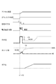
- FIG. 6 is a time chart when a target shift stage is determined during precharge when downshifting from the seventh speed in the precharge control process of Embodiment 1.
- FIG. 1 is a skeleton diagram showing the configuration of an automatic transmission that achieves the FR type 7-speed forward and reverse 1-speed of Embodiment 1 and an overall system diagram showing the control configuration of the automatic transmission.
- the automatic transmission according to the first embodiment is connected to the engine Eg via a torque converter TC in which a lockup clutch LUC is mounted.
- the rotation output from the engine Eg rotationally drives the pump impeller and the oil pump OP of the torque converter TC.
- the oil stirred by the rotation of the pump impeller is transmitted to the turbine runner through the stator, and drives the input shaft Input.
- An engine controller (hereinafter referred to as “ECU”) 10 that controls the drive state of the engine Eg and an automatic transmission controller (hereinafter referred to as “ATCU”) 20 that controls the shift state of the automatic transmission and the like.
- a control valve unit CVU that performs hydraulic control of each fastening element based on the output signal of the ATCU 20.
- the ECU 10 and the ATCU 20 are connected via a CAN communication line or the like, and share sensor information and control information with each other by communication.
- the ECU 10 is connected to an APO sensor 1 that detects the amount of accelerator pedal operation by the driver and an engine speed sensor 2 that detects the engine speed.
- the ECU 10 controls the fuel injection amount and the throttle opening based on the engine speed and the accelerator pedal operation amount, and controls the engine output speed and the engine torque.
- the ATCU 20 includes a first turbine rotation speed sensor 3 that detects the rotation speed of a first carrier PC1, which will be described later, a second turbine rotation speed sensor 4 that detects the rotation speed of the first ring gear R1, and the rotation speed of the output shaft Output. Is connected to an output shaft rotational speed sensor 5 and an inhibitor switch 6 for detecting a driver's shift lever operation state.
- the shift lever is an engine brake in which an engine brake is applied in addition to P, R, N, and D. A range position and a normal forward travel range position where the engine brake does not act are provided.
- the optimum command shift speed is determined from the shift map for the seventh forward speed shown in FIG. 5 based on the vehicle speed Vsp and the accelerator pedal opening APO when normal. And a control unit for outputting a control command for achieving the command shift speed to the control valve unit CVU.
- the first planetary gear set GS1 and the second planetary gear set GS2 are arranged in this order from the input shaft Input side toward the axial output shaft Output side.
- a plurality of clutches C1, C2, C3 and brakes B1, B2, B3, B4 are arranged as frictional engagement elements.
- a plurality of one-way clutches F1 and F2 are arranged.
- the first planetary gear G1 is a single pinion planetary gear having a first sun gear S1, a first ring gear R1, and a first carrier PC1 that supports a first pinion P1 that meshes with both gears S1 and R1.
- the second planetary gear G2 is a single pinion type planetary gear having a second sun gear S2, a second ring gear R2, and a second carrier PC2 that supports a second pinion P2 that meshes with both gears S2 and R2.
- the third planetary gear G3 is a single pinion planetary gear having a third sun gear S3, a third ring gear R3, and a third carrier PC3 that supports a third pinion P3 that meshes with both gears S3 and R3.
- the fourth planetary gear G4 is a single pinion planetary gear having a fourth sun gear S4, a fourth ring gear R4, and a fourth carrier PC4 that supports a fourth pinion P4 that meshes with both the gears S4, R4.
- the input shaft Input is connected to the second ring gear R2 and inputs the rotational driving force from the engine Eg via the torque converter TC or the like.
- the output shaft Output is connected to the third carrier PC3, and transmits the output rotational driving force to the driving wheels via a final gear or the like (not shown).
- the first connecting member M1 is a member that integrally connects the first ring gear R1, the second carrier PC2, and the fourth ring gear R4.
- the second connecting member M2 is a member that integrally connects the third ring gear R3 and the fourth carrier PC4.
- the third connecting member M3 is a member that integrally connects the first sun gear S1 and the second sun gear S2.
- the first planetary gear set GS1 is configured by connecting a first planetary gear G1 and a second planetary gear G2 by a first connecting member M1 and a third connecting member M3, and is configured by four rotating elements.
- the second planetary gear set GS2 includes a third planetary gear G3 and a fourth planetary gear G4 connected by a second connecting member M2 and configured by five rotating elements.
- the first planetary gear set GS1 has a torque input path that is input from the input shaft Input to the second ring gear R2.
- the torque input to the first planetary gear set GS1 is output from the first connecting member M1 to the second planetary gear set GS2.
- the second planetary gear set GS2 has a torque input path that is input from the input shaft Input to the second connection member M2, and a torque input path that is input from the first connection member M1 to the fourth ring gear R4.
- the torque input to the second planetary gear set GS2 is output from the third carrier PC3 to the output shaft Output.
- the input clutch C1 is a clutch that selectively connects and disconnects the input shaft Input and the second connecting member M2.
- the direct clutch C2 is a clutch that selectively connects and disconnects the fourth sun gear S4 and the fourth carrier PC4.
- the H & LR clutch C3 is a clutch that selectively connects and disconnects the third sun gear S3 and the fourth sun gear S4.
- a second one-way clutch F2 is disposed between the third sun gear S3 and the fourth sun gear.
- the front brake B1 is a brake that selectively stops the rotation of the first carrier PC1.
- the first one-way clutch F1 is disposed in parallel with the front brake B1.
- the low brake B2 is a brake that selectively stops the rotation of the third sun gear S3.
- the 2-3-4-6 brake B3 is a brake that selectively stops the rotation of the third connecting member M3 (the first sun gear S1 and the second sun gear S2).
- the reverse brake B4 is a brake that selectively stops the rotation of the fourth carrier PC4.
- FIG. 2 is a circuit diagram showing a hydraulic circuit of the control valve unit CVU.
- the circuit configuration will be described below.
- the hydraulic circuit according to the first embodiment includes an oil pump OP as a hydraulic source driven by an engine, a manual valve MV that switches an oil passage that supplies a line pressure PL in conjunction with a driver's shift lever operation, and a line A pilot valve PV is provided to reduce the pressure to a predetermined constant pressure.
- a first pressure regulating valve CV1 for regulating the engagement pressure of the low brake B2, a second pressure regulating valve CV2 for regulating the engagement pressure of the input clutch C1, a third pressure regulating valve CV3 for regulating the engagement pressure of the front brake B1,
- a fourth pressure regulation valve CV4 for regulating the engagement pressure of the H & RL clutch C3, a fifth pressure regulation valve CV5 for regulating the engagement pressure of the 2346 brake B3, and a sixth pressure regulation valve CV6 for regulating the engagement pressure of the direct clutch C2 are provided. Yes.
- the second switching valve SV2 that switches the direct clutch C2 to the state where only one of the supply oil passages of the D range pressure and the R range pressure communicates, and the hydraulic pressure supplied to the reverse brake B4 are the sixth pressure regulating valve CV6.
- the third switching valve SV3 that switches between the supply hydraulic pressure from the R range pressure and the supply hydraulic pressure from the R range pressure, and the fourth switching that switches the hydraulic pressure output from the sixth pressure regulating valve CV6 between the oil passage 123 and the oil passage 122 A valve SV4 is provided.
- a first solenoid valve SOL1 that outputs a pressure regulating signal to the first pressure regulating valve CV1, and a second solenoid valve SOL2 that outputs a pressure regulating signal to the second pressure regulating valve CV2;
- the third solenoid valve SOL3 that outputs a pressure regulating signal to the third pressure regulating valve CV3, the fourth solenoid valve SOL4 that outputs the pressure regulating signal to the fourth pressure regulating valve CV4, and the pressure regulated to the fifth pressure regulating valve CV5
- a fifth solenoid valve SOL5 that outputs a signal
- a sixth solenoid valve SOL6 that outputs a pressure regulation signal to the sixth pressure regulation valve CV6, and a seventh solenoid valve SOL7 that outputs a switching signal to the third switching valve SV3 are provided. It has been.
- Each of the solenoid valves SOL2, SOL5 and SOL6 is a three-way proportional solenoid valve having three ports.
- the first port is supplied with pilot pressure described later, the second port is connected to a drain oil passage, Each port is connected to a pressure receiving portion of a pressure regulating valve or a switching valve.
- the solenoid valves SOL1, SOL3, and SOL4 are two-way proportional solenoid valves having two ports, and the solenoid valve SOL7 is a three-way on / off solenoid valve having three ports.
- the first solenoid valve SOL1, the third solenoid valve SOL3, and the seventh solenoid valve SOL7 are normally closed types (closed when not energized).
- the second solenoid valve SOL2, the fourth solenoid valve SOL4, the fifth solenoid valve SOL5, and the sixth solenoid valve SOL6 are of a normally open type (open state when not energized).
- the discharge pressure of the oil pump OP driven by the engine is adjusted to the line pressure and then supplied to the oil passage 101 and the oil passage 102.
- the oil passage 101 includes an oil passage 101a connected to a manual valve MV that operates in conjunction with the driver's shift lever operation, an oil passage 101b that supplies the original pressure of the fastening pressure of the front brake B1, and an H & LR clutch C3.
- An oil passage 101c that supplies the original pressure of the fastening pressure is connected.
- the manual valve MV is connected to an oil passage 105 and an oil passage 106 that supplies an R range pressure selected during reverse travel, and switches between the oil passage 105 and the oil passage 106 in accordance with a shift lever operation.
- oil passage 105 there are an oil passage 105a that supplies the original pressure of the engagement pressure of the low brake B2, an oil passage 105b that supplies the original pressure of the engagement pressure of the input clutch C1, and an original pressure of the engagement pressure of the 2346 brake B3.
- An oil passage 105c to be supplied, an oil passage 105d to supply an original pressure of the engagement pressure of the direct clutch C2, and an oil passage 105e to supply a switching pressure of a second switching valve SV2 described later are connected.
- an oil passage 106a that supplies the switching pressure of the second switching valve SV2, an oil passage 106b that supplies the original pressure of the engagement pressure of the direct clutch C2, and an oil passage that supplies the engagement pressure of the reverse brake B4. 106c is connected.
- An oil passage 103 for supplying pilot pressure is connected to the oil passage 102 via a pilot valve PV.
- the oil passage 103 has an oil passage 103a for supplying pilot pressure to the first solenoid valve SOL1, an oil passage 103b for supplying pilot pressure to the second solenoid valve SOL2, and an oil for supplying pilot pressure to the third solenoid valve SOL3.
- an oil passage 103g for supplying pilot pressure to the seventh solenoid valve SOL7 And an oil passage 103g for supplying pilot pressure to the seventh solenoid valve SOL7.
- the first pressure regulating valve CV1 has a first port connected to the oil passage 105a, a second port connected to the drain circuit, a third port connected to the oil passage 115a connected to the low brake B2, The fourth port to which the signal pressure of the first solenoid valve SOL1 is supplied, the fifth port to which the oil passage fed back from the oil passage 115a as the counter pressure of this signal pressure is connected, and the hydraulic pressure supplied to the fourth port There is provided a spring that acts oppositely.
- the first pressure regulating valve CV1 moves upward, the oil passage 105a communicates with the oil passage 115a, while when moved downward, the oil passage 115a communicates with the drain.
- the second pressure regulating valve CV2 to the sixth pressure regulating valve CV6 are provided with the same configuration as the first port to the fifth port and the spring, and thus the description thereof is omitted.
- the second switching valve SV2 has a first port connected to the oil passage 105d for supplying the D range pressure, a second port connected to the oil passage 106d for supplying the R range pressure, and the sixth pressure regulating valve CV6.
- a third port connected to an oil passage 120 for supplying hydraulic pressure, a fourth port connected to an oil passage 105e for supplying D-range pressure, and an oil passage 106a for supplying an R-range pressure as a counter pressure of the fourth port.
- a spring acting opposite to the hydraulic pressure supplied to the fourth port In FIG. 2, when the second switching valve SV2 moves to the right, the oil passage 106b communicates with the oil passage 120, while when moved to the left, the oil passage 105d communicates with the oil passage 120.
- the third switching valve SV3 includes a first port connected to an oil passage 122 that supplies hydraulic pressure from the fourth switching valve SV4, a second port connected to an oil passage 106c that supplies R range pressure, and reverse
- the third port connected to the oil passage 130 for supplying hydraulic pressure to the brake B4, the fourth port connected to the oil passage 140a for supplying the signal pressure of the seventh solenoid valve SOL7, and the fourth port d4 are supplied.
- a spring is provided to act against the hydraulic pressure. In FIG. 2, when the third switching valve SV3 moves to the right, the oil passage 106c and the oil passage 130 are communicated, and when moved to the left, the oil passage 122 and the oil passage 130 are communicated.
- the fourth switching valve SV4 has a first port connected to the oil passage 121 for supplying hydraulic pressure from the sixth pressure regulating valve CV6, a second port and a third port connected to the drain circuit, and an R range pressure.
- the fourth port to be supplied, the fifth port to which the D-range pressure is supplied, the spring acting opposite to the fourth port, the seventh port connected to the oil passage 122, and the oil passage 123.
- An eighth port is provided.
- FIG. 2 when the fourth switching valve SV4 moves to the right, the oil passage 121 and the oil passage 123 communicate with each other and the oil passage 122 and the drain circuit communicate with each other.
- the fourth switching valve SV4 moves to the left, 122 and the oil passage 123 and the drain circuit are communicated.
- FIG. 3 is a diagram showing an engagement operation table for forward 7-speed reverse 1-speed in the gear transmission for an automatic transmission according to the first embodiment
- FIG. 4 is an operation table for solenoid valves SOL1 to SOL7 at each gear stage. .
- the clutches C1, C2, C3 and brakes B1, B2, B3, B4 are in a normal state, as shown in the engagement operation table of FIG. ) And release pressure (no mark).
- the front brake B1 and the H & LR clutch C3 are released, only the low brake B2 is engaged, and torque is transmitted by the first one-way clutch F1 and the second one-way clutch F2.
- the first to third solenoid valves SOL1 to SOL3 and the sixth and seventh solenoid valves SOL6 and SOL7 are turned on, and the others are turned off.
- the fastening pressure is supplied to the fastening elements.
- the first, second, fifth to seventh solenoid valves SOL1, SOL2, SOL5, SOL6, SOL7 are turned on and the others are turned off.
- a fastening pressure is supplied to the desired fastening element.
- the third speed is obtained by engaging the 2-3-4-6 brake B3, the low brake B2, and the direct clutch C2, as shown in FIG.
- the 2-3-4-6 brake B3 since the 2-3-4-6 brake B3 is engaged, the rotation input from the input shaft Input to the second ring gear R2 is decelerated by the second planetary gear G2. This decelerated rotation is output from the first connecting member M1 to the fourth ring gear R4.
- the direct clutch C2 since the direct clutch C2 is engaged, the fourth planetary gear G4 rotates integrally.
- the low brake B2 since the low brake B2 is engaged, the rotation input to the third ring gear R3 via the second connecting member M2 from the fourth carrier PC4 that rotates integrally with the fourth ring gear R4 is the third planetary gear G3.
- the fourth planetary gear G4 is involved in torque transmission but not in deceleration.
- the first, second, fourth, fifth and seventh solenoid valves SOL1, SOL2, SOL4, SOL5, SOL7 are turned on, and the others are turned off.
- the fastening pressure is supplied to the desired fastening element.
- the fourth speed is obtained by engaging the 2-3-4-6 brake B3, the direct clutch C2, and the H & LR clutch C3.
- the rotation input from the input shaft Input to the second ring gear R2 is decelerated only by the second planetary gear G2.
- This decelerated rotation is output from the first connecting member M1 to the fourth ring gear R4.
- the direct clutch C2 and the H & LR clutch C3 are engaged, the second planetary gear set GS2 rotates integrally. Therefore, the rotation input to the fourth ring gear R4 is output from the third carrier PC3 as it is.
- the second and fifth solenoid valves SOL2 and SOL5 are turned on, and the others are turned off, whereby the fastening pressure is supplied to a desired fastening element.
- the fifth speed is obtained by engaging the input clutch C1, the direct clutch C2, and the H & LR clutch C3.
- the rotation of the input shaft Input is input to the second connecting member M2.
- the direct clutch C2 and the H & LR clutch C3 are engaged, the third planetary gear G3 rotates integrally. Therefore, the rotation of the input shaft Input is output as it is from the third carrier PC3.
- the solenoid valve operation table of FIG. 4 by turning off all the solenoid valves SOL1 to SOL7, a fastening pressure is supplied to a desired fastening element.
- the sixth speed is obtained by engaging the input clutch C1, the H & LR clutch C3, and the 2-3-4-6 brake B3.
- the rotation of the input shaft Input is input to the second ring gear and also to the second connecting member M2.
- the 2-3-4-6 brake B3 is engaged, the rotation decelerated by the second planetary gear G2 is output from the first connecting member M1 to the fourth ring gear R4.
- the second planetary gear set GS2 outputs the rotation defined by the rotation of the fourth ring gear R4 and the rotation of the second connecting member M4 from the third carrier PC3.
- the fifth and sixth solenoid valves SOL5, SOL6 are turned on, and the other solenoid valves SOL1, SOL2, SOL3, SOL4, SOL7 are turned off.
- the fastening pressure is supplied to the fastening elements.
- the seventh speed is obtained by engaging the input clutch C1, the H & LR clutch C3, and the front brake B1 (first one-way clutch F1).
- the seventh speed since the input clutch C1 is engaged, the rotation of the input shaft Input is input to the second ring gear and also to the second connecting member M2.
- the front brake B1 since the front brake B1 is engaged, the rotation decelerated by the first planetary gear set GS1 is output from the first connecting member M1 to the fourth ring gear R4.
- the second planetary gear set GS2 outputs the rotation defined by the rotation of the fourth ring gear R4 and the rotation of the second connecting member M4 from the third carrier PC3.
- the third and sixth solenoid valves SOL3, SOL6 are turned on, and the other solenoid valves SOL1, SOL2, SOL4, SOL5, SOL7 are turned off.
- the fastening pressure is supplied to the fastening elements.
- the reverse speed is obtained by engaging the H & LR clutch C3, the front brake B1, and the reverse brake B4.
- the second, third and sixth solenoid valves SOL2, SOL3, SOL6 are turned on, and the other solenoid valves SOL1, SOL4, SOL5, SOL7 are turned off.
- the seventh solenoid SOL7 is turned on at the initial stage of R range switching, and turned off after completion of the fastening.
- FIG. 5 is a diagram showing a downshift line in the shift map of the first embodiment.
- the gear position in the region to which the operating point defined by the vehicle speed VSP and the accelerator pedal opening APO belongs is set as the target gear position.
- the shift line shown in FIG. 5 is a downshift line.
- the downshift request is output when the downshift line is crossed.
- an upshift line (not shown) is also set in the shift map in the same manner, and an upshift request is output when the operating point crosses the upshift line when moving from the low shift speed region to the high shift speed region. .
- the current operating point is p1 in the 7th speed region.
- the driving point moves upward in FIG. 5 from p1, and there is a possibility of movement such as p2, p3, p4, and p5 (hereinafter, the possibility of movement occurs).
- the shift speed is referred to as a temporary shift speed.
- the extent to which the driver depresses the accelerator pedal cannot be determined when the 7-6 downshift line is crossed. Therefore, normally, for example, an APO change rate indicating a change in driving point is obtained until a predetermined time that is considered to be settled, or even before the predetermined time elapses.
- the determination of the target shift stage is prohibited. Then, after a predetermined time has elapsed after crossing the 7-6 downshift line, or before the predetermined time has elapsed and the APO change rate is equal to or lower than a predetermined value, the target shift stage is determined and the downshift is executed. .
- FIG. 8 is a time chart in a case where all friction engagement elements are precharged in a state where the discharge flow rate of the oil pump is insufficient as a comparative example.
- FIG. 9 is a time chart in the case of sequentially precharging one friction engagement element as a comparative example.
- a downshift request is output, precharge is started, and when the target shift stage is determined at time t2, even if the discharge flow rate of the oil pump is secured, the precharge is performed sequentially.
- the discharge flow rate of the oil pump OP is estimated from when the downshift request is output until the target shift speed is determined, and the estimated discharge flow rate is preliminarily applied to the frictional engagement element of the temporary shift speed.
- FIG. 6 is a control block diagram showing the precharge control of the first embodiment.
- the discharge flow rate estimation unit 201 estimates and calculates the discharge flow rate of the oil pump OP based on the engine speed Ne and the automatic transmission oil temperature Ta.
- the leak amount calculation unit 202 calculates a leak amount leaking from each friction engagement element, a valve, and the like based on the line pressure PL and the automatic transmission oil temperature Ta. For example, in the friction engagement element that has already been engaged, the amount of oil that compensates for the leak is consumed, and thus that amount is estimated and calculated.
- the surplus flow rate calculation unit 203 calculates the surplus flow rate Qb by subtracting the leak amount from the estimated discharge flow rate.
- the stroke required flow rate calculation unit 204 individually calculates the precharge amount of the frictional engagement element that needs to be precharged based on the information on the provisional shift stage. Then, priorities are set in order from the smallest difference from the gear ratio of the current gear, and information on each precharge amount and priority is output. For example, as indicated by the operating points described in the shift map in FIG. 5, the current shift stage is the seventh speed, and the temporary shift stages are the sixth speed, the fifth speed, the fourth speed, and the third speed. In this case, the gear stage having the highest priority is the sixth speed, and the gear stage having the lowest priority is the third speed. Further, as shown in the engagement table of FIG.
- the flow rate combination calculation unit 205 calculates the first required flow rate Qa and the second required flow rate Qc based on each precharge amount and priority. For example, in the case of downshift from the seventh speed, the first required flow rate Qa is determined by the precharge amount of 2-3-4-6 brake B3, the precharge amount of the direct clutch C2, and the precharge amount of the low brake B2. It is the sum.
- the second required flow rate Qc is a flow rate obtained by combining the two in descending order of priority, and is the sum of the precharge amount of the 2-3-4-6 brake B3 and the precharge amount of the direct clutch C2.
- the simultaneous charge availability determination unit 206 compares the surplus flow rate Qb with the first necessary flow rate Qa and compares the surplus flow rate Qb with the second necessary flow rate Qc. If Qb ⁇ Qa, all can be precharged simultaneously. If Qc ⁇ Qb ⁇ Qa, it is determined that two of the higher priority levels can be precharged simultaneously, and if Qb ⁇ Qc, it is determined that precharge is performed sequentially sequentially.
- the precharge command calculation unit 207 outputs a precharge command based on the determination result of the simultaneous charge availability determination unit 206 and the priority order information of the stroke required flow rate calculation unit 204. For example, in the case of downshift from the 7th speed, when Qb ⁇ Qa, a command to precharge all of the 2-3-4-6 brake B3, the direct clutch C2 and the low brake B2 is output at the same time, and Qc ⁇ Qb ⁇ When Qa, a command to precharge the 2-3-4-6 brake B3 and the direct clutch C2 at the same time is output, and thereafter a command to precharge the low brake B2 is output. When Qb ⁇ Qc, 2 -3-4-6 Precharge commands are output individually in the order of brake B3 ⁇ direct clutch C2 ⁇ low brake B2.
- FIG. 7 is a flowchart showing precharge control processing during downshifting according to the first embodiment.
- step S1 the possibility of a downshift request is determined.
- step S2 the control flow is terminated.
- step S2 friction engagement element determination is performed. Specifically, as described in the stroke required flow rate calculation unit 204, the friction engagement element that needs to be precharged based on the provisional shift stage is specified and the priority order is determined.
- step S3 the first required flow rate Qa is calculated.
- step S4 the surplus flow rate Qb is calculated.
- step S5 it is determined whether or not Qa ⁇ Qb ⁇ 0. If negative, the process proceeds to step S6, and if positive, the process proceeds to step S7. In step S6, all precharges are executed simultaneously.
- step S7 the second required flow rate Qc is calculated.
- step S8 it is determined whether Qb ⁇ Qc ⁇ 0. If positive, the process proceeds to step S9, and if negative, the process proceeds to step S10.
- step S9 two high priority items are precharged at the same time, and then the remaining precharges are executed.
- precharge is performed individually in order of priority.
- step S11 it is determined whether or not the target gear position is determined during precharge. If it is determined, the process proceeds to step S13, and otherwise, the process proceeds to step S12.
- step S12 it is determined whether or not all precharges are completed. If completed, this control flow is terminated. If not completed, the process returns to step S11 to continue the precharge.
- step S13 a precharge process after the target shift stage is determined is performed. For example, when the 2-3-4-6 brake B3 and the direct clutch C2 are simultaneously precharged when a downshift is requested from the seventh speed, if the target shift speed is determined to be the fifth speed, -4-6 The charge rate of the direct clutch C2 is quickly increased by immediately stopping the precharge to the brake B3.
- FIG. 10 is a time chart when the oil pump discharge flow rate is sufficiently secured when downshifting from the seventh speed in the precharge control process of the first embodiment.
- FIG. 11 is a time chart when the oil pump discharge flow rate is Qc ⁇ Qb ⁇ Qa when downshifting from the seventh speed in the precharge control process of the first embodiment.
- precharge is simultaneously performed on the 2346 brake B3 and the direct clutch C2, and then precharge is performed on the low brake B2.
- the charge rate of the 2-3-4-6 brake B3 and the direct clutch C2 can be increased as compared with the case where all are precharged simultaneously.
- the precharge of the 2-3-4-6 brake B3 and the direct clutch C2 can be completed in a shorter time compared to the case where the precharges are sequentially performed one by one.
- FIG. 12 is a time chart when the target shift stage is determined during precharge when downshifting from the seventh speed in the precharge control process of the first embodiment.
- a downshift request is output, and all the frictional engagement elements based on the provisional shift stage are precharged.
- 2-3-4-6 brake B3 and low brake B2 are precharged immediately. And only precharge of the direct clutch C2 is continued. As a result, quick precharge is possible, and a highly responsive shift can be realized without causing engine blow-up or a decrease in shift speed.
- the first required flow rate Qa which is the amount of oil required for precharging to stroke the piston of the frictional engagement element from the release position to the engagement position, is estimated, and it is determined whether the first required flow rate Qa can be discharged from the oil pump OP.
- precharge is performed with all friction engagement elements (2-3-4-6 brake B3, direct clutch C2, low brake B2) of the temporary shift stage, otherwise there is a possibility of shifting
- the frictional engagement elements that are engaged at a certain speed are precharged, and then the frictional engagement elements that are engaged at other speeds that are likely to be shifted are precharged.
- the number of friction engagement elements that precharge is changed according to the oil pump discharge flow rate, engine blow-up and shift shock due to insufficient precharge are suppressed, and reduction in shift response due to precharge delay is suppressed. it can.
- the difference in gear ratio with respect to the predetermined shift speed among the temporary shift speeds is smaller than in other gear speeds where there is a possibility of shifting.
- the friction engagement element that is engaged at a gear position close to the gear position at the start of gear shifting is precharged, for example, the change rate of the accelerator pedal opening APO becomes small after the accelerator pedal is operated, so Even when the speed is determined as the target shift speed, a highly responsive shift can be achieved.
- precharge for the frictional engagement elements other than the frictional engagement elements that are engaged at the determined shift speed is terminated. Therefore, quick precharging can be performed for the determined shift stage, and a highly responsive shift can be realized without causing engine blow-up or a decrease in shift speed.
- the precharge control is performed when there is a downshift request, but may be performed when an upshift request is made.
- the priority of the friction engagement elements is increased according to the gear position close to the gear position when the downshift request is output. For example, depending on the capacity of the friction engagement elements and the torque sharing ratio, Priorities may be determined.
- the necessary flow rate associated with the combination of the other friction engagement elements is calculated in addition to the second necessary flow rate Qc, and the combination thereof is calculated. From the optimal order.
- a plurality of precharges are performed at the first precharge, and after completion of the precharge, again based on the relationship between the discharge flow rate of the oil pump and the required flow rate. A plurality of precharges may be performed.
Landscapes
- Engineering & Computer Science (AREA)
- General Engineering & Computer Science (AREA)
- Mechanical Engineering (AREA)
- Control Of Transmission Device (AREA)
Abstract
所定変速段での走行中に、変速の可能性があると判断すると、目標変速段が確定する前に、変速の可能性がある全ての変速段で締結される全ての摩擦締結要素のピストンを解放位置から締結位置にストロークさせるプリチャージに必要な油量を推定する。推定された油量がオイルポンプから吐出可能か否かを判断し、吐出可能なときは変速の可能性がある全ての変速段でプリチャージを行う。それ以外のときは、変速の可能性がある一部の変速段でプリチャージを行い、その後、変速の可能性がある他の変速段で締結される摩擦締結要素のプリチャージを行う。これにより、変速ショックや変速応答性の低下を抑制可能となる。
Description
本発明は、自動変速機の制御装置に関する。
自動変速機の制御装置として特許文献1に記載の技術が知られている。この特許文献1に記載された技術では、5速から4速へのアクセルペダル踏み込みに伴うダウンシフト中に、3速及び2速時に係合する摩擦締結要素にピストンのロスストローク分を補償する係合準備油圧(以下、「プリチャージ圧」と称する。)を同時に作用させ、これにより他の変速段への要求が行われた際の応答性を確保している。
近年、有段式自動変速機は更なる多段化が行われており、同時にプリチャージする変速段の数が増大すると、油量不足となって変速ショックや変速応答性の低下を招くおそれがあった。
本発明は、上記課題に着目してなされたもので、変速ショックや変速応答性の低下を抑制可能な自動変速機の制御装置を提供することを目的とする。
上記目的を達成するため、本発明の自動変速機の制御装置にあっては、所定変速段での走行中に、変速の可能性があると判断すると、目標変速段が確定する前に、変速の可能性がある全ての変速段で締結される全ての摩擦締結要素のピストンを解放位置から締結位置にストロークさせるプリチャージに必要な油量を推定し、推定された必要な油量がオイルポンプから吐出可能か否かを判断し、吐出可能なときは変速の可能性がある全ての変速段で締結される全ての摩擦締結要素のプリチャージを行い、それ以外のときは変速の可能性がある一部の変速段で締結される摩擦締結要素のプリチャージを行い、その後、変速の可能性がある他の変速段で締結される摩擦締結要素のプリチャージを行うこととした。
すなわち、オイルポンプ吐出流量に応じてプリチャージを行う摩擦締結要素の数を変更するため、プリチャージ不足によるエンジン吹き上がりや変速ショックを抑制し、また、プリチャージ遅れによる変速応答性の低下を抑制できる。
図1は実施例1のFR型の前進7速後退1速を達成する自動変速機の構成を表すスケルトン図及び自動変速機の制御構成を表す全体システム図である。実施例1の自動変速機は、エンジンEgに対し、ロックアップクラッチLUCが装着されたトルクコンバータTCを介して接続されている。エンジンEgから出力された回転は、トルクコンバータTCのポンプインペラ及びオイルポンプOPを回転駆動する。このポンプインペラの回転により攪拌されたオイルはステータを介してタービンランナに伝達され、入力軸Inputを駆動する。
また、エンジンEgの駆動状態を制御するエンジンコントローラ(以下、「ECU」と称する。)10と、自動変速機の変速状態等を制御する自動変速機コントローラ(以下、「ATCU」と称する。)20と、ATCU20の出力信号に基づいて各締結要素の油圧制御を実行するコントロールバルブユニットCVUと、が設けられている。尚、ECU10とATCU20とは、CAN通信線等を介して接続され、相互にセンサ情報や制御情報を通信により共有している。
ECU10には、運転者のアクセルペダル操作量を検出するAPOセンサ1と、エンジン回転数を検出するエンジン回転数センサ2が接続されている。ECU10は、エンジン回転数やアクセルペダル操作量に基づいて燃料噴射量やスロットル開度を制御し、エンジン出力回転数及びエンジントルクを制御する。
ATCU20には、後述する第1キャリヤPC1の回転数を検出する第1タービン回転数センサ3と、第1リングギヤR1の回転数を検出する第2タービン回転数センサ4と、出力軸Outputの回転数を検出する出力軸回転数センサ5と、運転者のシフトレバー操作状態を検出するインヒビタスイッチ6が接続されており、シフトレバーはP,R,N,Dの他にエンジンブレーキが作用するエンジンブレーキレンジ位置とエンジンブレーキが作用しない通常前進走行レンジ位置とを備える。
ATCU20内では、入力軸Inputの回転数を演算する回転数算出部と共に、正常時には車速Vspとアクセルペダル開度APOに基づいて、図5に示す前進7速段の変速マップから最適な指令変速段を選択し、コントロールバルブユニットCVUに指令変速段を達成する制御指令を出力する変速制御部が設けられている。
〈自動変速機の構成について〉
次に、自動変速機の構成について説明する。入力軸Input側から軸方向出力軸Output側に向けて、第1遊星ギヤセットGS1,第2遊星ギヤセットGS2の順に配置されている。また、摩擦締結要素として複数のクラッチC1,C2,C3及びブレーキB1,B2,B3,B4が配置されている。また、複数のワンウェイクラッチF1,F2が配置されている。
次に、自動変速機の構成について説明する。入力軸Input側から軸方向出力軸Output側に向けて、第1遊星ギヤセットGS1,第2遊星ギヤセットGS2の順に配置されている。また、摩擦締結要素として複数のクラッチC1,C2,C3及びブレーキB1,B2,B3,B4が配置されている。また、複数のワンウェイクラッチF1,F2が配置されている。
第1遊星ギヤG1は、第1サンギヤS1と、第1リングギヤR1と、両ギヤS1,R1に噛み合う第1ピニオンP1を支持する第1キャリヤPC1と、を有するシングルピニオン型遊星ギヤである。
第2遊星ギヤG2は、第2サンギヤS2と、第2リングギヤR2と、両ギヤS2,R2に噛み合う第2ピニオンP2を支持する第2キャリヤPC2と、を有するシングルピニオン型遊星ギヤである。
第3遊星ギヤG3は、第3サンギヤS3と、第3リングギヤR3と、両ギヤS3,R3に噛み合う第3ピニオンP3を支持する第3キャリヤPC3と、を有するシングルピニオン型遊星ギヤである。
第4遊星ギヤG4は、第4サンギヤS4と、第4リングギヤR4と、両ギヤS4,R4に噛み合う第4ピニオンP4を支持する第4キャリヤPC4と、を有するシングルピニオン型遊星ギアである。
第2遊星ギヤG2は、第2サンギヤS2と、第2リングギヤR2と、両ギヤS2,R2に噛み合う第2ピニオンP2を支持する第2キャリヤPC2と、を有するシングルピニオン型遊星ギヤである。
第3遊星ギヤG3は、第3サンギヤS3と、第3リングギヤR3と、両ギヤS3,R3に噛み合う第3ピニオンP3を支持する第3キャリヤPC3と、を有するシングルピニオン型遊星ギヤである。
第4遊星ギヤG4は、第4サンギヤS4と、第4リングギヤR4と、両ギヤS4,R4に噛み合う第4ピニオンP4を支持する第4キャリヤPC4と、を有するシングルピニオン型遊星ギアである。
入力軸Inputは、第2リングギヤR2に連結され、エンジンEgからの回転駆動力を、トルクコンバータTC等を介して入力する。
出力軸Outputは、第3キャリヤPC3に連結され、出力回転駆動力を図外のファイナルギヤ等を介して駆動輪に伝達する。
出力軸Outputは、第3キャリヤPC3に連結され、出力回転駆動力を図外のファイナルギヤ等を介して駆動輪に伝達する。
第1連結メンバM1は、第1リングギヤR1と第2キャリヤPC2と第4リングギヤR4とを一体的に連結するメンバである。
第2連結メンバM2は、第3リングギヤR3と第4キャリヤPC4とを一体的に連結するメンバである。
第3連結メンバM3は、第1サンギヤS1と第2サンギヤS2とを一体的に連結するメンバである。
第2連結メンバM2は、第3リングギヤR3と第4キャリヤPC4とを一体的に連結するメンバである。
第3連結メンバM3は、第1サンギヤS1と第2サンギヤS2とを一体的に連結するメンバである。
第1遊星ギヤセットGS1は、第1遊星ギヤG1と第2遊星ギヤG2とを、第1連結メンバM1と第3連結メンバM3により連結して構成し4つの回転要素から構成している。また、第2遊星ギヤセットGS2は、第3遊星ギヤG3と第4遊星ギヤG4とを、第2連結メンバM2により連結し5つの回転要素から構成している。
第1遊星ギヤセットGS1は、入力軸Inputから第2リングギヤR2に入力されるトルク入力経路を有する。第1遊星ギヤセットGS1に入力されたトルクは、第1連結メンバM1から第2遊星ギヤセットGS2に出力される。
第2遊星ギヤセットGS2は、入力軸Inputから第2連結メンバM2に入力されるトルク入力経路と、第1連結メンバM1から第4リングギヤR4に入力されるトルク入力経路を有する。第2遊星ギヤセットGS2に入力されたトルクは、第3キャリヤPC3から出力軸Outputに出力される。
尚、H&LRクラッチC3が解放され、第3サンギヤS3よりも第4サンギヤS4の回転数が大きい時は、第3サンギヤS3と第4サンギヤS4は独立した回転数を発生する。よって、第3遊星ギヤG3と第4遊星ギヤG4が第2連結メンバM2を介して接続された構成となり、それぞれの遊星ギヤが独立したギヤ比を達成する。
第1遊星ギヤセットGS1は、入力軸Inputから第2リングギヤR2に入力されるトルク入力経路を有する。第1遊星ギヤセットGS1に入力されたトルクは、第1連結メンバM1から第2遊星ギヤセットGS2に出力される。
第2遊星ギヤセットGS2は、入力軸Inputから第2連結メンバM2に入力されるトルク入力経路と、第1連結メンバM1から第4リングギヤR4に入力されるトルク入力経路を有する。第2遊星ギヤセットGS2に入力されたトルクは、第3キャリヤPC3から出力軸Outputに出力される。
尚、H&LRクラッチC3が解放され、第3サンギヤS3よりも第4サンギヤS4の回転数が大きい時は、第3サンギヤS3と第4サンギヤS4は独立した回転数を発生する。よって、第3遊星ギヤG3と第4遊星ギヤG4が第2連結メンバM2を介して接続された構成となり、それぞれの遊星ギヤが独立したギヤ比を達成する。
インプットクラッチC1は、入力軸Inputと第2連結メンバM2とを選択的に断接するクラッチである。
ダイレクトクラッチC2は、第4サンギヤS4と第4キャリヤPC4とを選択的に断接するクラッチである。
H&LRクラッチC3は、第3サンギヤS3と第4サンギヤS4とを選択的に断接するクラッチである。尚、第3サンギヤS3と第4サンギヤの間には、第2ワンウェイクラッチF2が配置されている。
フロントブレーキB1は、第1キャリヤPC1の回転を選択的に停止させるブレーキである。また、第1ワンウェイクラッチF1は、フロントブレーキB1と並列に配置されている。
ローブレーキB2は、第3サンギヤS3の回転を選択的に停止させるブレーキである。
2-3-4-6ブレーキB3は、第3連結メンバM3(第1サンギヤS1及び第2サンギヤS2)の回転を選択的に停止させるブレーキである。
リバースブレーキB4は、第4キャリヤPC4の回転を選択的に停止させるブレーキである。
ダイレクトクラッチC2は、第4サンギヤS4と第4キャリヤPC4とを選択的に断接するクラッチである。
H&LRクラッチC3は、第3サンギヤS3と第4サンギヤS4とを選択的に断接するクラッチである。尚、第3サンギヤS3と第4サンギヤの間には、第2ワンウェイクラッチF2が配置されている。
フロントブレーキB1は、第1キャリヤPC1の回転を選択的に停止させるブレーキである。また、第1ワンウェイクラッチF1は、フロントブレーキB1と並列に配置されている。
ローブレーキB2は、第3サンギヤS3の回転を選択的に停止させるブレーキである。
2-3-4-6ブレーキB3は、第3連結メンバM3(第1サンギヤS1及び第2サンギヤS2)の回転を選択的に停止させるブレーキである。
リバースブレーキB4は、第4キャリヤPC4の回転を選択的に停止させるブレーキである。
〈コントロールバルブユニットの構成について〉
図2はコントロールバルブユニットCVUの油圧回路を表す回路図である。以下、回路構成について説明する。実施例1の油圧回路には、エンジンにより駆動された油圧源としてのオイルポンプOPと、運転者のシフトレバー操作と連動して、ライン圧PLを供給する油路を切り換えるマニュアルバルブMVと、ライン圧を所定の一定圧に減圧するパイロットバルブPVが設けられている。
図2はコントロールバルブユニットCVUの油圧回路を表す回路図である。以下、回路構成について説明する。実施例1の油圧回路には、エンジンにより駆動された油圧源としてのオイルポンプOPと、運転者のシフトレバー操作と連動して、ライン圧PLを供給する油路を切り換えるマニュアルバルブMVと、ライン圧を所定の一定圧に減圧するパイロットバルブPVが設けられている。
また、ローブレーキB2の締結圧を調圧する第1調圧弁CV1と、インプットクラッチC1の締結圧を調圧する第2調圧弁CV2と、フロントブレーキB1の締結圧を調圧する第3調圧弁CV3と、H&RLクラッチC3の締結圧を調圧する第4調圧弁CV4と、2346ブレーキB3の締結圧を調圧する第5調圧弁CV5と、ダイレクトクラッチC2の締結圧を調圧する第6調圧弁CV6が設けられている。
また、ダイレクトクラッチC2に対しDレンジ圧とRレンジ圧の供給油路をどちらか一方のみ連通する状態に切り換える第2切換弁SV2と、リバースブレーキB4に対して供給する油圧を第6調圧弁CV6からの供給油圧とRレンジ圧からの供給油圧との間で切り換える第3切換弁SV3と、第6調圧弁CV6から出力された油圧を油路123と油路122との間で切り換える第4切換弁SV4が設けられている。
また、ATCU20からの制御信号に基づいて、第1調圧弁CV1に対し調圧信号を出力する第1ソレノイドバルブSOL1と、第2調圧弁CV2に対し調圧信号を出力する第2ソレノイドバルブSOL2と、第3調圧弁CV3に対し調圧信号を出力する第3ソレノイドバルブSOL3と、第4調圧弁CV4に対し調圧信号を出力する第4ソレノイドバルブSOL4と、第5調圧弁CV5に対し調圧信号を出力する第5ソレノイドバルブSOL5と、第6調圧弁CV6に対し調圧信号を出力する第6ソレノイドバルブSOL6と、第3切換弁SV3に対し切り換え信号を出力する第7ソレノイドバルブSOL7が設けられている。
上記各ソレノイドバルブSOL2,SOL5,SOL6は三つのポートを有する三方比例電磁弁であり、第1のポートは後述するパイロット圧が導入され、第2のポートはドレーン油路に接続され、第3のポートはそれぞれ調圧弁もしくは切換弁の受圧部に接続されている。また、上記各ソレノイドバルブSOL1,SOL3,SOL4は2つのポートを有する二方比例電磁弁、ソレノイドバルブSOL7は三つのポートを備える三方オンオフ電磁弁である。
また、第1ソレノイドバルブSOL1と第3ソレノイドバルブSOL3と第7ソレノイドバルブSOL7はノーマルクローズタイプ(非通電時に閉じた状態)とされている。一方、第2ソレノイドバルブSOL2と第4ソレノイドバルブSOL4と第5ソレノイドバルブSOL5と第6ソレノイドバルブSOL6はノーマルオープンタイプ(非通電時に開いた状態)とされている。
〈油路構成について〉
エンジンにより駆動されるオイルポンプOPの吐出圧は、ライン圧に調圧された後、油路101及び油路102に供給される。油路101には、運転者のシフトレバー操作に連動して作動するマニュアルバルブMVと接続された油路101aと、フロントブレーキB1の締結圧の元圧を供給する油路101bと、H&LRクラッチC3の締結圧の元圧を供給する油路101cが接続されている。
エンジンにより駆動されるオイルポンプOPの吐出圧は、ライン圧に調圧された後、油路101及び油路102に供給される。油路101には、運転者のシフトレバー操作に連動して作動するマニュアルバルブMVと接続された油路101aと、フロントブレーキB1の締結圧の元圧を供給する油路101bと、H&LRクラッチC3の締結圧の元圧を供給する油路101cが接続されている。
マニュアルバルブMVには、油路105と、後退走行時に選択されるRレンジ圧を供給する油路106が接続され、シフトレバー操作に応じて油路105と油路106を切り換える。
油路105には、ローブレーキB2の締結圧の元圧を供給する油路105aと、インプットクラッチC1の締結圧の元圧を供給する油路105bと、2346ブレーキB3の締結圧の元圧を供給する油路105cと、ダイレクトクラッチC2の締結圧の元圧を供給する油路105dと、後述する第2切換弁SV2の切り換え圧を供給する油路105eが接続されている。
油路106には、第2切換弁SV2の切り換え圧を供給する油路106aと、ダイレクトクラッチC2の締結圧の元圧を供給する油路106bと、リバースブレーキB4の締結圧を供給する油路106cが接続されている。
油路102にはパイロットバルブPVを介してパイロット圧を供給する油路103が接続されている。油路103には、第1ソレノイドバルブSOL1にパイロット圧を供給する油路103aと、第2ソレノイドバルブSOL2にパイロット圧を供給する油路103bと、第3ソレノイドバルブSOL3にパイロット圧を供給する油路103cと、第4ソレノイドバルブSOL4にパイロット圧を供給する油路103dと、第5ソレノイドバルブSOL5にパイロット圧を供給する油路103eと、第6ソレノイドバルブSOL6にパイロット圧を供給する油路103fと、第7ソレノイドバルブSOL7にパイロット圧を供給する油路103gとが設けられている。
第1調圧弁CV1には、油路105aが接続される第1ポートと、ドレーン回路に接続された第2ポートと、ローブレーキB2と接続される油路115aが接続される第3ポートと、第1ソレノイドバルブSOL1の信号圧が供給される第4ポートと、この信号圧の対向圧として油路115aからフィードバックされた油路が接続された第5ポートと、第4ポートに供給される油圧に対向して作用するスプリングが設けられている。図2中、第1調圧弁CV1が上方に移動すると油路105aと油路115aが連通され、一方、下方に移動すると油路115aとドレーンとが連通される。同様に、第2調圧弁CV2~第6調圧弁CV6には、第1ポート~第5ポート及びスプリングと同じ構成が設けられているため説明を省略する。
第2切換弁SV2には、Dレンジ圧を供給する油路105dと接続された第1ポートと、Rレンジ圧を供給する油路106dと接続された第2ポートと、第6調圧弁CV6へ油圧を供給する油路120と接続された第3ポートと、Dレンジ圧を供給する油路105eと接続された第4ポートと、第4ポートの対向圧としてRレンジ圧を供給する油路106aと接続された第5ポートと、第4ポートに供給される油圧に対向して作用するスプリングが設けられている。図2中、第2切換弁SV2が右方に移動すると油路106bと油路120が連通され、一方、左方に移動すると油路105dと油路120が連通される。
第3切換弁SV3には、第4切換弁SV4からの油圧を供給する油路122と接続された第1ポートと、Rレンジ圧を供給する油路106cと接続された第2ポートと、リバースブレーキB4に油圧を供給する油路130と接続された第3ポートと、第7ソレノイドバルブSOL7の信号圧を供給する油路140aと接続された第4ポートと、第4ポートd4に供給される油圧に対向して作用するスプリングが設けられている。図2中、第3切換弁SV3が右方に移動すると油路106cと油路130が連通され、一方、左方に移動すると油路122と油路130とが連通される。
第4切換弁SV4には、第6調圧弁CV6からの油圧を供給する油路121と接続された第1ポートと、ドレーン回路に接続された第2ポート及び第3ポートと、Rレンジ圧が供給される第4ポートと、Dレンジ圧が供給される第5ポートと、第4ポートに対向して作用するスプリングと、油路122と接続された第7ポートと、油路123と接続された第8ポートが設けられている。図2中、第4切換弁SV4が右方に移動すると油路121と油路123が連通されると共に油路122とドレーン回路が連通され、一方、左方に移動すると油路121と油路122が連通されると共に油路123とドレーン回路が連通される。
次に、作用を説明する。
[変速作用]
図3は実施例1の自動変速機用歯車変速装置での前進7速後退1速の締結作動表を示す図、図4は各変速段におけるソレノイドバルブSOL1~SOL7の作動表を表す図である。各クラッチC1,C2,C3及び各ブレーキB1,B2,B3,B4には、正常時には図3の締結作動表に示すように、前進7速後退1速の各変速段にて締結圧(○印)や解放圧(無印)が供給される。
[変速作用]
図3は実施例1の自動変速機用歯車変速装置での前進7速後退1速の締結作動表を示す図、図4は各変速段におけるソレノイドバルブSOL1~SOL7の作動表を表す図である。各クラッチC1,C2,C3及び各ブレーキB1,B2,B3,B4には、正常時には図3の締結作動表に示すように、前進7速後退1速の各変速段にて締結圧(○印)や解放圧(無印)が供給される。
〈1速〉
1速は、エンジンブレーキ作用時(エンジンブレーキレンジ位置選択中)とエンジンブレーキ非作用時(通常前進走行レンジ位置選択中)とで異なる締結要素が作用する。エンジンブレーキ作用時は、図3の(○印)で示すように、フロントブレーキB1とローブレーキB2とH&LRクラッチC3との締結により得られる。尚、フロントブレーキB1に並列に設けられた第1ワンウェイクラッチF1と、H&LRクラッチC3と並列に設けられた第2ワンウェイクラッチF2もトルク伝達に関与する。エンジンブレーキ非作用時は、フロントブレーキB1とH&LRクラッチC3は解放され、ローブレーキB2のみが締結され、第1ワンウェイクラッチF1と第2ワンウェイクラッチF2によりトルク伝達される。
このとき、図4のソレノイドバルブ作動表に示すように、第1~第3ソレノイドバルブSOL1~SOL3及び第6及び第7ソレノイドバルブSOL6,SOL7をオンとし、それ以外をオフとすることで、所望の締結要素に締結圧が供給される。
1速は、エンジンブレーキ作用時(エンジンブレーキレンジ位置選択中)とエンジンブレーキ非作用時(通常前進走行レンジ位置選択中)とで異なる締結要素が作用する。エンジンブレーキ作用時は、図3の(○印)で示すように、フロントブレーキB1とローブレーキB2とH&LRクラッチC3との締結により得られる。尚、フロントブレーキB1に並列に設けられた第1ワンウェイクラッチF1と、H&LRクラッチC3と並列に設けられた第2ワンウェイクラッチF2もトルク伝達に関与する。エンジンブレーキ非作用時は、フロントブレーキB1とH&LRクラッチC3は解放され、ローブレーキB2のみが締結され、第1ワンウェイクラッチF1と第2ワンウェイクラッチF2によりトルク伝達される。
このとき、図4のソレノイドバルブ作動表に示すように、第1~第3ソレノイドバルブSOL1~SOL3及び第6及び第7ソレノイドバルブSOL6,SOL7をオンとし、それ以外をオフとすることで、所望の締結要素に締結圧が供給される。
〈2速〉
2速は、エンジンブレーキ作用時(エンジンブレーキレンジ位置選択中)とエンジンブレーキ非作用時(通常前進走行レンジ位置選択中)とで異なる締結要素が締結する。エンジンブレーキ作用時は、図3の(○印)で示すように、ローブレーキB2と2-3-4-6ブレーキB3とH&LRクラッチC3との締結により得られる。尚、H&LRクラッチC3と並列に設けられた第2ワンウェイクラッチF2もトルク伝達に関与する。エンジンブレーキ非作動時は、H&LRクラッチC3は解放され、ローブレーキB2と2-3-4-6ブレーキB3が締結され、第2ワンウェイクラッチF2によりトルク伝達される。
このとき、図4のソレノイドバルブ作動表に示すように、第1,第2,第5~第7ソレノイドバルブSOL1,SOL2,SOL5,SOL6,SOL7をオンとし、それ以外をオフとすることで、所望の締結要素に締結圧が供給される。
2速は、エンジンブレーキ作用時(エンジンブレーキレンジ位置選択中)とエンジンブレーキ非作用時(通常前進走行レンジ位置選択中)とで異なる締結要素が締結する。エンジンブレーキ作用時は、図3の(○印)で示すように、ローブレーキB2と2-3-4-6ブレーキB3とH&LRクラッチC3との締結により得られる。尚、H&LRクラッチC3と並列に設けられた第2ワンウェイクラッチF2もトルク伝達に関与する。エンジンブレーキ非作動時は、H&LRクラッチC3は解放され、ローブレーキB2と2-3-4-6ブレーキB3が締結され、第2ワンウェイクラッチF2によりトルク伝達される。
このとき、図4のソレノイドバルブ作動表に示すように、第1,第2,第5~第7ソレノイドバルブSOL1,SOL2,SOL5,SOL6,SOL7をオンとし、それ以外をオフとすることで、所望の締結要素に締結圧が供給される。
〈3速〉
3速は、図3に示すように、2-3-4-6ブレーキB3とローブレーキB2とダイレクトクラッチC2との締結により得られる。
この3速では、2-3-4-6ブレーキB3が締結されているため、入力軸Inputから第2リングギヤR2に入力された回転は、第2遊星ギアG2により減速される。この減速された回転が第1連結メンバM1から第4リングギヤR4に出力される。また、ダイレクトクラッチC2が締結されているため、第4遊星ギヤG4は一体となって回転する。また、ローブレーキB2が締結されているため、第4リングギヤR4と一体に回転する第4キャリヤPC4から第2連結メンバM2を介して第3リングギヤR3に入力された回転は、第3遊星ギヤG3により減速され、第3キャリヤPC3から出力される。このように第4遊星ギヤG4はトルク伝達に関与するが減速作用には関与しない。
このとき、図4のソレノイドバルブ作動表に示すように、第1,第2,第4,5及び第7ソレノイドバルブSOL1,SOL2,SOL4,SOL5,SOL7をオンとし、それ以外をオフとすることで、所望の締結要素に締結圧が供給される。
3速は、図3に示すように、2-3-4-6ブレーキB3とローブレーキB2とダイレクトクラッチC2との締結により得られる。
この3速では、2-3-4-6ブレーキB3が締結されているため、入力軸Inputから第2リングギヤR2に入力された回転は、第2遊星ギアG2により減速される。この減速された回転が第1連結メンバM1から第4リングギヤR4に出力される。また、ダイレクトクラッチC2が締結されているため、第4遊星ギヤG4は一体となって回転する。また、ローブレーキB2が締結されているため、第4リングギヤR4と一体に回転する第4キャリヤPC4から第2連結メンバM2を介して第3リングギヤR3に入力された回転は、第3遊星ギヤG3により減速され、第3キャリヤPC3から出力される。このように第4遊星ギヤG4はトルク伝達に関与するが減速作用には関与しない。
このとき、図4のソレノイドバルブ作動表に示すように、第1,第2,第4,5及び第7ソレノイドバルブSOL1,SOL2,SOL4,SOL5,SOL7をオンとし、それ以外をオフとすることで、所望の締結要素に締結圧が供給される。
〈4速〉
4速は、図3に示すように、2-3-4-6ブレーキB3とダイレクトクラッチC2とH&LRクラッチC3との締結により得られる。
この4速では、2-3-4-6ブレーキB3が締結されているため、入力軸Inputから第2リングギヤR2に入力された回転は、第2遊星ギヤG2のみにより減速される。この減速された回転が第1連結メンバM1から第4リングギヤR4に出力される。また、ダイレクトクラッチC2及びH&LRクラッチC3が締結されているため、第2遊星ギヤセットGS2は一体で回転する。よって、第4リングギヤR4に入力された回転は、そのまま第3キャリヤPC3から出力される。
このとき、図4のソレノイドバルブ作動表に示すように、第2及び第5ソレノイドバルブSOL2,SOL5をオンとし、それ以外をオフとすることで、所望の締結要素に締結圧が供給される。
4速は、図3に示すように、2-3-4-6ブレーキB3とダイレクトクラッチC2とH&LRクラッチC3との締結により得られる。
この4速では、2-3-4-6ブレーキB3が締結されているため、入力軸Inputから第2リングギヤR2に入力された回転は、第2遊星ギヤG2のみにより減速される。この減速された回転が第1連結メンバM1から第4リングギヤR4に出力される。また、ダイレクトクラッチC2及びH&LRクラッチC3が締結されているため、第2遊星ギヤセットGS2は一体で回転する。よって、第4リングギヤR4に入力された回転は、そのまま第3キャリヤPC3から出力される。
このとき、図4のソレノイドバルブ作動表に示すように、第2及び第5ソレノイドバルブSOL2,SOL5をオンとし、それ以外をオフとすることで、所望の締結要素に締結圧が供給される。
〈5速〉
5速は、図3に示すように、インプットクラッチC1とダイレクトクラッチC2とH&LRクラッチC3との締結により得られる。
この5速では、インプットクラッチC1が締結されているため、入力軸Inputの回転は第2連結メンバM2に入力される。また、ダイレクトクラッチC2及びH&LRクラッチC3が締結されているため、第3遊星ギヤG3は一体で回転する。よって、入力軸Inputの回転は、そのまま第3キャリヤPC3から出力される。
このとき、図4のソレノイドバルブ作動表に示すように、全てのソレノイドバルブSOL1~SOL7をオフとすることで、所望の締結要素に締結圧が供給される。
5速は、図3に示すように、インプットクラッチC1とダイレクトクラッチC2とH&LRクラッチC3との締結により得られる。
この5速では、インプットクラッチC1が締結されているため、入力軸Inputの回転は第2連結メンバM2に入力される。また、ダイレクトクラッチC2及びH&LRクラッチC3が締結されているため、第3遊星ギヤG3は一体で回転する。よって、入力軸Inputの回転は、そのまま第3キャリヤPC3から出力される。
このとき、図4のソレノイドバルブ作動表に示すように、全てのソレノイドバルブSOL1~SOL7をオフとすることで、所望の締結要素に締結圧が供給される。
〈6速〉
6速は、図3に示すように、インプットクラッチC1とH&LRクラッチC3と2-3-4-6ブレーキB3の締結により得られる。
この6速では、インプットクラッチC1が締結されているため、入力軸Inputの回転は第2リングギヤに入力されると共に、第2連結メンバM2に入力される。また、2-3-4-6ブレーキB3が締結されているため、第2遊星ギヤG2により減速された回転が第1連結メンバM1から第4リングギヤR4に出力される。また、H&LRクラッチC3が締結されているため、第2遊星ギヤセットGS2は、第4リングギヤR4の回転と、第2連結メンバM4の回転によって規定される回転を第3キャリヤPC3から出力する。
このとき、図4のソレノイドバルブ作動表に示すように、第5及び第6ソレノイドバルブSOL5,SOL6をオンとし、他のソレノイドバルブSOL1,SOL2,SOL3,SOL4,SOL7をオフとすることで、所望の締結要素に締結圧が供給される。
6速は、図3に示すように、インプットクラッチC1とH&LRクラッチC3と2-3-4-6ブレーキB3の締結により得られる。
この6速では、インプットクラッチC1が締結されているため、入力軸Inputの回転は第2リングギヤに入力されると共に、第2連結メンバM2に入力される。また、2-3-4-6ブレーキB3が締結されているため、第2遊星ギヤG2により減速された回転が第1連結メンバM1から第4リングギヤR4に出力される。また、H&LRクラッチC3が締結されているため、第2遊星ギヤセットGS2は、第4リングギヤR4の回転と、第2連結メンバM4の回転によって規定される回転を第3キャリヤPC3から出力する。
このとき、図4のソレノイドバルブ作動表に示すように、第5及び第6ソレノイドバルブSOL5,SOL6をオンとし、他のソレノイドバルブSOL1,SOL2,SOL3,SOL4,SOL7をオフとすることで、所望の締結要素に締結圧が供給される。
〈7速〉
7速は、図3に示すように、インプットクラッチC1とH&LRクラッチC3とフロントブレーキB1(第1ワンウェイクラッチF1)の締結により得られる。
この7速では、インプットクラッチC1が締結されているため、入力軸Inputの回転は第2リングギヤに入力されると共に、第2連結メンバM2に入力される。また、フロントブレーキB1が締結されているため、第1遊星ギヤセットGS1により減速された回転が第1連結メンバM1から第4リングギヤR4に出力される。また、H&LRクラッチC3が締結されているため、第2遊星ギヤセットGS2は、第4リングギヤR4の回転と、第2連結メンバM4の回転によって規定される回転を第3キャリヤPC3から出力する。
このとき、図4のソレノイドバルブ作動表に示すように、第3及び第6ソレノイドバルブSOL3,SOL6をオンとし、他のソレノイドバルブSOL1,SOL2,SOL4,SOL5,SOL7をオフとすることで、所望の締結要素に締結圧が供給される。
7速は、図3に示すように、インプットクラッチC1とH&LRクラッチC3とフロントブレーキB1(第1ワンウェイクラッチF1)の締結により得られる。
この7速では、インプットクラッチC1が締結されているため、入力軸Inputの回転は第2リングギヤに入力されると共に、第2連結メンバM2に入力される。また、フロントブレーキB1が締結されているため、第1遊星ギヤセットGS1により減速された回転が第1連結メンバM1から第4リングギヤR4に出力される。また、H&LRクラッチC3が締結されているため、第2遊星ギヤセットGS2は、第4リングギヤR4の回転と、第2連結メンバM4の回転によって規定される回転を第3キャリヤPC3から出力する。
このとき、図4のソレノイドバルブ作動表に示すように、第3及び第6ソレノイドバルブSOL3,SOL6をオンとし、他のソレノイドバルブSOL1,SOL2,SOL4,SOL5,SOL7をオフとすることで、所望の締結要素に締結圧が供給される。
〈後退速〉
後退速は、図3に示すように、H&LRクラッチC3とフロントブレーキB1とリバースブレーキB4の締結により得られる。
このとき、図4のソレノイドバルブ作動表に示すように、第2,第3及び第6ソレノイドバルブSOL2,SOL3,SOL6をオンとし、他のソレノイドバルブSOL1,SOL4,SOL5,SOL7をオフとすることで、所望の締結要素に締結圧が供給される。尚、第7ソレノイドSOL7についてはRレンジ切り換え初期はオンとし、締結完了後にオフとする。
後退速は、図3に示すように、H&LRクラッチC3とフロントブレーキB1とリバースブレーキB4の締結により得られる。
このとき、図4のソレノイドバルブ作動表に示すように、第2,第3及び第6ソレノイドバルブSOL2,SOL3,SOL6をオンとし、他のソレノイドバルブSOL1,SOL4,SOL5,SOL7をオフとすることで、所望の締結要素に締結圧が供給される。尚、第7ソレノイドSOL7についてはRレンジ切り換え初期はオンとし、締結完了後にオフとする。
〈シフト時プリチャージ制御処理〉
図5は実施例1の変速マップのうちダウンシフト線を示す図である。車速VSPとアクセルペダル開度APOによって規定される運転点の属する領域の変速段が目標変速段として設定される。図5に示す変速線は、ダウンシフト線であり、運転点が高変速段領域から低変速段領域へ移動する際にダウンシフト線を横切ると、ダウンシフト要求が出力される。尚、変速マップには図示しないアップシフト線も同様に設定されており、運転点が低変速段領域から高変速段領域へ移動する際にアップシフト線を横切ると、アップシフト要求が出力される。
図5は実施例1の変速マップのうちダウンシフト線を示す図である。車速VSPとアクセルペダル開度APOによって規定される運転点の属する領域の変速段が目標変速段として設定される。図5に示す変速線は、ダウンシフト線であり、運転点が高変速段領域から低変速段領域へ移動する際にダウンシフト線を横切ると、ダウンシフト要求が出力される。尚、変速マップには図示しないアップシフト線も同様に設定されており、運転点が低変速段領域から高変速段領域へ移動する際にアップシフト線を横切ると、アップシフト要求が出力される。
例えば、現在の運転点が7速領域であるp1とする。このとき、運転者がアクセルペダルを踏み込むと、運転点はp1から図5中の上方に移動し、p2,p3,p4,p5といった移動を行う可能性が生じる(以下、移動の可能性が生じる変速段を暫定変速段と称する。)。ここで、運転者がアクセルペダルをどの程度踏み込むか、については7-6ダウンシフト線を横切った時点では確定できない。そこで、通常は、運転者のアクセルペダル操作が落ち着くと考えられる予め設定された所定時間が経過するまで、もしくは所定時間が経過する前であっても、例えば運転点の変化を表すAPO変化率が所定値以下となるまでは、目標変速段の確定を禁止する。そして、7-6ダウンシフト線を横切ってから所定時間経過後、もしくは所定時間経過前であってAPO変化率が所定値以下となった場合は、目標変速段を確定してダウンシフトを実行する。
このとき、ダウンシフト要求が出力されてから目標変速段が確定するまでの間にプリチャージを行わず、目標変速段が決定されてからプリチャージを開始すると、応答性の悪化を招く。特に、摩擦締結要素のピストンを解放位置から締結位置にストロークさせるプリチャージには時間がかかり、かつ、この期間にトルク伝達を行うことができない。よって、目標変速段が確定する前であっても、暫定変速段で締結される摩擦締結要素に対して事前にプリチャージを行うことで、変速応答性を確保することが考えられる。
図8は比較例として、オイルポンプの吐出流量が不足した状態で全ての摩擦締結要素にプリチャージを行った場合のタイムチャートである。時刻t1において、ダウンシフト要求が出力されると、暫定変速段で締結する摩擦締結要素にプリチャージを開始する。このとき、オイルポンプOPの吐出流量には制限があり、特に高変速段からのダウンシフトのように、エンジン回転数が比較的低回転状態で複数の摩擦締結要素にプリチャージを行うと、油量不足からプリチャージによる各摩擦締結要素のストローク率を表すチャージ率が低くなる。そうすると、時刻t2において、目標変速段が確定してダウンシフトを開始したとしても、チャージ率不足によって締結圧上昇に遅れが生じる。よって、時刻t3においてダイレクトクラッチC2のプリチャージが終了したとしても、ローブレーキB2のチャージ率が不十分となり、時刻t4において、ローブレーキB2の指示圧を上昇させても締結できずに、エンジン回転数が吹け上がることによる変速ショックの悪化を招くおそれがある。
図9は比較例として、一つの摩擦締結要素に順次プリチャージを行った場合のタイムチャートである。時刻t1において、ダウンシフト要求が出力され、プリチャージを開始し、時刻t2において目標変速段が確定すると、オイルポンプの吐出流量が確保されている場合であっても、順次プリチャージを行うため、特に最後にプリチャージを開始するローブレーキB2のチャージ率が上昇するまでに時間がかかり、ギア比が変化するイナーシャフェーズの進行速度不足による変速応答性の低下を招くというおそれがあった。
そこで、実施例1では、ダウンシフト要求が出力されてから目標変速段が確定するまでの間、オイルポンプOPの吐出流量を推定し、推定された吐出流量によって暫定変速段の摩擦締結要素にプリチャージが可能か否かを判断し、可能な場合は暫定変速段の全てにプリチャージを行い、不可能な場合は、優先順位をつけてプリチャージを行うことで、変速応答性を確保することとした。
図6は実施例1のプリチャージ制御を表す制御ブロック図である。吐出流量推定部201では、エンジン回転数Neと自動変速機内油温Taに基づいてオイルポンプOPの吐出流量を推定演算する。リーク量演算部202では、ライン圧PLと自動変速機内油温Taに基づいて、各摩擦締結要素やバルブ等からリークするリーク量を演算する。例えば、既に締結が完了している摩擦締結要素では、リークを補償する分の油量が消費されるため、その分を推定演算する。余剰流量算出部203では、推定演算された吐出流量からリーク量を差し引いて余剰流量Qbを算出する。
ストローク必要流量演算部204では、暫定変速段の情報に基づいてプリチャージが必要な摩擦締結要素のプリチャージ量を個別に演算する。そして、現在の変速段のギア比との差が小さいものから順に優先順位を設定し、各プリチャージ量及び優先順位の情報を出力する。例えば、図5の変速マップ内に記載した運転点に示すように、現在の変速段が7速、暫定変速段は6速,5速,4速,3速である。この場合、優先度が最も高い変速段は6速となり、優先度が最も低い変速段は3速となる。また、図3の締結表に示すように、7速から6速に変速するには、2-3-4-6ブレーキB3にプリチャージを行う必要があり、7速から5速に変速するにはダイレクトクラッチC2にプリチャージを行う必要があり、7速から4速に変速するには2-3-4-6ブレーキB3とダイレクトクラッチC2にプリチャージを行う必要があり、7速から3速に変速するには2-3-4-6ブレーキB3とダイレクトクラッチC2とローブレーキB2にプリチャージを行う必要がある。よって、プリチャージの優先度を高い順に並べると、2-3-4-6ブレーキB3,ダイレクトクラッチC2,ローブレーキB2となる。これら各摩擦締結要素に必要とされるプリチャージ量を個別に演算する。
流量組み合わせ演算部205では、各プリチャージ量と優先順位に基づいて第1必要流量Qa及び第2必要流量Qcを演算する。例えば、7速からのダウンシフトの場合、第1必要流量Qaは、2-3-4-6ブレーキB3のプリチャージ量と、ダイレクトクラッチC2のプリチャージ量と、ローブレーキB2のプリチャージ量の合計である。第2必要流量Qcは、優先度の高い順に2つを組み合わせた流量であり、2-3-4-6ブレーキB3のプリチャージ量とダイレクトクラッチC2のプリチャージ量との合計である。
同時チャージ可否判断部206では、余剰流量Qbと第1必要流量Qaとの大小比較及び余剰流量Qbと第2必要流量Qcとの大小比較を行い、Qb≧Qaならば全て同時にプリチャージが可能と判定し、Qc≦Qb<Qaならば、優先度が高い2つを同時にプリチャージが可能と判定し、Qb<Qcならば、個別に順次プリチャージを行うと判定する。
プリチャージ指令演算部207では、同時チャージ可否判断部206の判断結果及びストローク必要流量演算部204の優先順位情報に基づいてプリチャージ指令を出力する。例えば、7速からのダウンシフトの場合、Qb≧Qaのときは、2-3-4-6ブレーキB3,ダイレクトクラッチC2及びローブレーキB2を全て同時にプリチャージする指令を出力し、Qc≦Qb<Qaのときは、2-3-4-6ブレーキB3及びダイレクトクラッチC2を同時にプリチャージする指令を出力し、その後、ローブレーキB2をプリチャージする指令を出力し、Qb<Qcのときは、2-3-4-6ブレーキB3→ダイレクトクラッチC2→ローブレーキB2の順に個別にプリチャージ指令を出力する。
図7は実施例1のダウンシフト時におけるプリチャージ制御処理を表すフローチャートである。
ステップS1では、ダウンシフト要求の可能性を判断し、ダウンシフト要求が生じると判断したときはステップS2に進み、それ以外の場合は本制御フローを終了する。
ステップS2では、摩擦締結要素判定を行う。具体的にはストローク必要流量演算部204において説明したように、暫定変速段に基づくプリチャージが必要な摩擦締結要素の特定及び優先順位の決定を行う。
ステップS1では、ダウンシフト要求の可能性を判断し、ダウンシフト要求が生じると判断したときはステップS2に進み、それ以外の場合は本制御フローを終了する。
ステップS2では、摩擦締結要素判定を行う。具体的にはストローク必要流量演算部204において説明したように、暫定変速段に基づくプリチャージが必要な摩擦締結要素の特定及び優先順位の決定を行う。
ステップS3では、第1必要流量Qaを演算する。
ステップS4では、余剰流量Qbを演算する。
ステップS5では、Qa-Qb≦0か否かを判断し、負の場合はステップS6に進み、正の場合はステップS7に進む。
ステップS6では、全てのプリチャージを同時に実行する。
ステップS4では、余剰流量Qbを演算する。
ステップS5では、Qa-Qb≦0か否かを判断し、負の場合はステップS6に進み、正の場合はステップS7に進む。
ステップS6では、全てのプリチャージを同時に実行する。
ステップS7では、第2必要流量Qcを演算する。
ステップS8では、Qb-Qc≦0か否かを判断し、正の場合はステップS9に進み、負の場合はステップS10に進む。
ステップS9では、優先度が高い2つを同時にプリチャージし、その後、残りのプリチャージを実行する。
ステップS10では、優先度の高い順から個別にプリチャージを実行する。
ステップS8では、Qb-Qc≦0か否かを判断し、正の場合はステップS9に進み、負の場合はステップS10に進む。
ステップS9では、優先度が高い2つを同時にプリチャージし、その後、残りのプリチャージを実行する。
ステップS10では、優先度の高い順から個別にプリチャージを実行する。
ステップS11では、プリチャージ中に目標変速段が決定されたか否かを判断し、決定された場合はステップS13に進み、それ以外はステップS12に進む。
ステップS12では、プリチャージが全て完了したか否かを判断し、完了している場合は本制御フローを終了し、完了していない場合はステップS11に戻ってプリチャージを継続する。
ステップS13では、目標変速段決定後のプリチャージ処理を実施する。例えば、7速からのダウンシフト要求時に2-3-4-6ブレーキB3とダイレクトクラッチC2に同時にプリチャージを実施しているときに、目標変速段が5速に決定されると、2-3-4-6ブレーキB3へのプリチャージを即座に中止することで、ダイレクトクラッチC2のチャージ率を素早く上昇させる。
ステップS12では、プリチャージが全て完了したか否かを判断し、完了している場合は本制御フローを終了し、完了していない場合はステップS11に戻ってプリチャージを継続する。
ステップS13では、目標変速段決定後のプリチャージ処理を実施する。例えば、7速からのダウンシフト要求時に2-3-4-6ブレーキB3とダイレクトクラッチC2に同時にプリチャージを実施しているときに、目標変速段が5速に決定されると、2-3-4-6ブレーキB3へのプリチャージを即座に中止することで、ダイレクトクラッチC2のチャージ率を素早く上昇させる。
次に、上記制御フローに基づく作用について説明する。図10は、実施例1のプリチャージ制御処理において、7速からダウンシフトする際、オイルポンプ吐出流量が十分に確保された場合のタイムチャートである。暫定変速段に基づくプリチャージが必要な摩擦締結要素の全てにプリチャージを同時に行うことで、目標変速段が確定後は、エンジン吹き上がりや変速速度の低下を招くことなく応答性の高い変速を実現できる。
図11は、実施例1のプリチャージ制御処理において、7速からダウンシフトする際、オイルポンプ吐出流量がQc≦Qb<Qaの場合のタイムチャートである。暫定変速段に基づくプリチャージが必要な摩擦締結要素のうち、2346ブレーキB3とダイレクトクラッチC2とに同時にプリチャージを行い、その後、ローブレーキB2にプリチャージを行う。これにより、全てに同時にプリチャージを行う場合に比べて2-3-4-6ブレーキB3とダイレクトクラッチC2のチャージ率を高めることができる。また、最初に2つのプリチャージを同時に行うため、一つ一つ順次プリチャージを行う場合に比べて短時間で2-3-4-6ブレーキB3とダイレクトクラッチC2のプリチャージを完了できる。
図12は、実施例1のプリチャージ制御処理において、7速からダウンシフトする際、プリチャージ中に目標変速段が確定した場合のタイムチャートである。時刻t1においてダウンシフト要求が出力され、暫定変速段に基づく全ての摩擦締結要素にプリチャージを行っている。時刻t12において、運転者のアクセルペダル開度APOの変化率が所定値未満となり、目標変速段が5速に確定すると、2-3-4-6ブレーキB3及びローブレーキB2へのプリチャージを即座に終了し、ダイレクトクラッチC2のプリチャージのみ継続する。これにより、素早いプリチャージが可能となり、エンジン吹き上がりや変速速度の低下を招くことなく応答性の高い変速を実現できる。
以上説明したように、実施例1にあっては下記に列挙する作用効果を得ることができる。
(1)所定変速段での走行中に、変速の可能性があると判断すると、目標変速段が確定する前に、暫定変速段(全ての変速の可能性がある変速段)で締結される摩擦締結要素のピストンを解放位置から締結位置にストロークさせるプリチャージに必要な油量である第1必要流量Qaを推定し、第1必要流量QaがオイルポンプOPから吐出可能か否かを判断し、吐出可能なときは暫定変速段の全ての摩擦締結要素(2-3-4-6ブレーキB3、ダイレクトクラッチC2、ローブレーキB2)でプリチャージを行い、それ以外のときは変速の可能性がある一部の変速段で締結される摩擦締結要素のプリチャージを行い、その後、変速の可能性がある他の変速段で締結される摩擦締結要素のプリチャージを行うこととした。
すなわち、オイルポンプ吐出流量に応じてプリチャージを行う摩擦締結要素の数を変更するため、プリチャージ不足によるエンジン吹き上がりや変速ショックを抑制し、また、プリチャージ遅れによる変速応答性の低下を抑制できる。
(1)所定変速段での走行中に、変速の可能性があると判断すると、目標変速段が確定する前に、暫定変速段(全ての変速の可能性がある変速段)で締結される摩擦締結要素のピストンを解放位置から締結位置にストロークさせるプリチャージに必要な油量である第1必要流量Qaを推定し、第1必要流量QaがオイルポンプOPから吐出可能か否かを判断し、吐出可能なときは暫定変速段の全ての摩擦締結要素(2-3-4-6ブレーキB3、ダイレクトクラッチC2、ローブレーキB2)でプリチャージを行い、それ以外のときは変速の可能性がある一部の変速段で締結される摩擦締結要素のプリチャージを行い、その後、変速の可能性がある他の変速段で締結される摩擦締結要素のプリチャージを行うこととした。
すなわち、オイルポンプ吐出流量に応じてプリチャージを行う摩擦締結要素の数を変更するため、プリチャージ不足によるエンジン吹き上がりや変速ショックを抑制し、また、プリチャージ遅れによる変速応答性の低下を抑制できる。
(2)変速の可能性がある一部の変速段は、暫定変速段のうち、所定変速段とのギア比の差が、変速の可能性がある他の変速段よりも小さい。言い換えると、変速開始時の変速段に近い変速段で締結する摩擦締結要素にプリチャージを行うため、例えばアクセルペダルを操作後にアクセルペダル開度APOの変化率が小さくなり、早期の段階で近い変速段が目標変速段として確定する場合であっても、応答性の高い変速を達成できる。
(3)オイルポンプOPから吐出可能な油量Qbが、複数の摩擦締結要素のプリチャージに必要な油量以上のときは、変速の可能性がある一部の変速段は複数である。言い換えると、Qc≦Qb<Qaならば、複数の摩擦締結要素(2-3-4-6ブレーキB3、ダイレクトクラッチC2)に同時にプリチャージを行い、その後、他の摩擦締結要素(ローブレーキB2)にプリチャージを行うことで、順次プリチャージを行う場合よりも応答性の高い変速を実現できる。
(4)目標変速段が確定した後は、確定された変速段で締結される摩擦締結要素以外の摩擦締結要素に対するプリチャージを終了することとした。
よって、確定された変速段に対して素早いプリチャージが可能となり、エンジン吹き上がりや変速速度の低下を招くことなく応答性の高い変速を実現できる。
よって、確定された変速段に対して素早いプリチャージが可能となり、エンジン吹き上がりや変速速度の低下を招くことなく応答性の高い変速を実現できる。
以上、本発明を実施例1に基づいて説明したが、上記実施例に限らず、他の構成であっても構わない。例えば、実施例1ではダウンシフト要求がある場合にプリチャージ制御を行うこととしたが、アップシフト要求のときに実施してもよい。また、実施例1では、ダウンシフト要求が出力されたときの変速段に近い変速段に応じた摩擦締結要素の優先順位を高くしたが、例えば、摩擦締結要素の容量やトルク分担率に応じて優先順位を決定してもよい。
また、実施例1では前進7速の自動変速機を例に説明したが、更に多段化した自動変速機に適用してもよい。この場合、暫定変速段の増加に伴い、3つ以上のプリチャージが必要な場合には、第2必要流量Qcに加えて他の摩擦締結要素の組み合わせに伴う必要流量を演算し、それらの組み合わせから最適な順序で供給すればよい。また、暫定変速段の摩擦締結要素が4つ以上存在する場合、最初のプリチャージで複数のプリチャージを行い、このプリチャージ完了後、再度、オイルポンプの吐出流量と必要流量との関係に基づいて複数のプリチャージを行ってもよい。
Claims (4)
- 所定変速段での走行中に、変速の可能性があると判断すると、目標変速段が確定する前に、変速の可能性がある全ての変速段で締結される全ての摩擦締結要素のピストンを解放位置から締結位置にストロークさせるプリチャージに必要な油量を推定し、推定された必要な油量がオイルポンプから吐出可能か否かを判断し、吐出可能なときは変速の可能性がある全ての変速段で締結される全ての摩擦締結要素のプリチャージを行い、それ以外のときは一部の変速の可能性がある変速段でプリチャージを行い、その後、変速の可能性がある他の変速段で締結される摩擦締結要素のプリチャージを行うようにした自動変速機の制御装置。
- 請求項1に記載の自動変速機の制御装置において、
前記変速の可能性がある一部の変速段は、前記変速の可能性がある全ての変速段のうち、前記所定変速段とのギア比の差が、変速の可能性がある他の変速段よりも小さいものである自動変速機の制御装置。 - 請求項1または2に記載の自動変速機の制御装置において、
前記オイルポンプから吐出可能な油量が、複数の摩擦締結要素のプリチャージに必要な油量以上のときは、前記変速の可能性がある一部の変速段は複数である自動変速機の制御装置。 - 請求項1~3のいずれか一つに記載の自動変速機の制御装置において、
前記目標変速段が確定した後は、確定された変速段で締結される摩擦締結要素以外の摩擦締結要素に対するプリチャージを終了するようにした自動変速機の制御装置。
Applications Claiming Priority (2)
| Application Number | Priority Date | Filing Date | Title |
|---|---|---|---|
| JP2015190643A JP6471365B2 (ja) | 2015-09-29 | 2015-09-29 | 自動変速機の制御装置 |
| JP2015-190643 | 2015-09-29 |
Publications (1)
| Publication Number | Publication Date |
|---|---|
| WO2017056840A1 true WO2017056840A1 (ja) | 2017-04-06 |
Family
ID=58423387
Family Applications (1)
| Application Number | Title | Priority Date | Filing Date |
|---|---|---|---|
| PCT/JP2016/075592 Ceased WO2017056840A1 (ja) | 2015-09-29 | 2016-09-01 | 自動変速機の制御装置 |
Country Status (2)
| Country | Link |
|---|---|
| JP (1) | JP6471365B2 (ja) |
| WO (1) | WO2017056840A1 (ja) |
Families Citing this family (1)
| Publication number | Priority date | Publication date | Assignee | Title |
|---|---|---|---|---|
| JP7384775B2 (ja) * | 2020-10-09 | 2023-11-21 | トヨタ自動車株式会社 | 車両の制御装置 |
Citations (4)
| Publication number | Priority date | Publication date | Assignee | Title |
|---|---|---|---|---|
| JP2001317624A (ja) * | 2000-05-09 | 2001-11-16 | Unisia Jecs Corp | 車両用自動変速機の油圧制御装置 |
| JP2008223939A (ja) * | 2007-03-14 | 2008-09-25 | Toyota Motor Corp | 自動変速機の油圧制御装置 |
| JP2008275001A (ja) * | 2007-04-26 | 2008-11-13 | Toyota Motor Corp | 自動変速機の制御装置 |
| JP2008546962A (ja) * | 2005-06-22 | 2008-12-25 | ツェットエフ、フリードリッヒスハーフェン、アクチエンゲゼルシャフト | モータ乗り物のための自動変速機の駆動制御装置、および、そのための方法 |
-
2015
- 2015-09-29 JP JP2015190643A patent/JP6471365B2/ja active Active
-
2016
- 2016-09-01 WO PCT/JP2016/075592 patent/WO2017056840A1/ja not_active Ceased
Patent Citations (4)
| Publication number | Priority date | Publication date | Assignee | Title |
|---|---|---|---|---|
| JP2001317624A (ja) * | 2000-05-09 | 2001-11-16 | Unisia Jecs Corp | 車両用自動変速機の油圧制御装置 |
| JP2008546962A (ja) * | 2005-06-22 | 2008-12-25 | ツェットエフ、フリードリッヒスハーフェン、アクチエンゲゼルシャフト | モータ乗り物のための自動変速機の駆動制御装置、および、そのための方法 |
| JP2008223939A (ja) * | 2007-03-14 | 2008-09-25 | Toyota Motor Corp | 自動変速機の油圧制御装置 |
| JP2008275001A (ja) * | 2007-04-26 | 2008-11-13 | Toyota Motor Corp | 自動変速機の制御装置 |
Also Published As
| Publication number | Publication date |
|---|---|
| JP6471365B2 (ja) | 2019-02-20 |
| JP2017067106A (ja) | 2017-04-06 |
Similar Documents
| Publication | Publication Date | Title |
|---|---|---|
| KR101714047B1 (ko) | 자동 변속기의 제어 장치 및 그 학습 방법 | |
| JP4418477B2 (ja) | 自動変速機 | |
| JP4920064B2 (ja) | 自動変速機の制御装置 | |
| EP2161482B1 (en) | Control device for vehicle and control method thereof | |
| JP4951658B2 (ja) | 自動変速機の制御装置 | |
| KR101559180B1 (ko) | 자동 변속기의 변속 제어 장치 | |
| EP0802353A2 (en) | Clutch pressure control during skip or overlap shift of an automatic transmission | |
| JP4627328B2 (ja) | 自動変速機の制御装置 | |
| JP2003182408A (ja) | 自動変速機の制御装置 | |
| JP4649384B2 (ja) | 自動変速機の制御装置 | |
| JP6471365B2 (ja) | 自動変速機の制御装置 | |
| JP4849928B2 (ja) | 自動変速機の変速制御装置 | |
| JP4358248B2 (ja) | 自動変速機 | |
| JP6561337B2 (ja) | 自動変速機の制御装置 | |
| JP2630135B2 (ja) | 自動変速機の変速制御装置 | |
| JP5096431B2 (ja) | 自動変速機の制御装置およびその制御方法 | |
| JP5238062B2 (ja) | 自動変速機の制御装置 | |
| JP4499053B2 (ja) | 自動変速装置の制御装置 | |
| JP2008106829A (ja) | 車両用自動変速機の変速制御装置 | |
| JPS6280339A (ja) | 自動変速機のバツクアツプ圧制御装置 | |
| JPH10196775A (ja) | 自動変速機の油圧制御装置 |
Legal Events
| Date | Code | Title | Description |
|---|---|---|---|
| 121 | Ep: the epo has been informed by wipo that ep was designated in this application |
Ref document number: 16851016 Country of ref document: EP Kind code of ref document: A1 |
|
| NENP | Non-entry into the national phase |
Ref country code: DE |
|
| 122 | Ep: pct application non-entry in european phase |
Ref document number: 16851016 Country of ref document: EP Kind code of ref document: A1 |