WO2017056624A1 - 車両用アウトサイドハンドル装置 - Google Patents
車両用アウトサイドハンドル装置 Download PDFInfo
- Publication number
- WO2017056624A1 WO2017056624A1 PCT/JP2016/070389 JP2016070389W WO2017056624A1 WO 2017056624 A1 WO2017056624 A1 WO 2017056624A1 JP 2016070389 W JP2016070389 W JP 2016070389W WO 2017056624 A1 WO2017056624 A1 WO 2017056624A1
- Authority
- WO
- WIPO (PCT)
- Prior art keywords
- guide protrusion
- distance
- support member
- vehicle
- outside handle
- Prior art date
- Legal status (The legal status is an assumption and is not a legal conclusion. Google has not performed a legal analysis and makes no representation as to the accuracy of the status listed.)
- Ceased
Links
Images









Classifications
-
- B—PERFORMING OPERATIONS; TRANSPORTING
- B60—VEHICLES IN GENERAL
- B60J—WINDOWS, WINDSCREENS, NON-FIXED ROOFS, DOORS, OR SIMILAR DEVICES FOR VEHICLES; REMOVABLE EXTERNAL PROTECTIVE COVERINGS SPECIALLY ADAPTED FOR VEHICLES
- B60J5/00—Doors
- B60J5/04—Doors arranged at the vehicle sides
-
- E—FIXED CONSTRUCTIONS
- E05—LOCKS; KEYS; WINDOW OR DOOR FITTINGS; SAFES
- E05B—LOCKS; ACCESSORIES THEREFOR; HANDCUFFS
- E05B85/00—Details of vehicle locks not provided for in groups E05B77/00 - E05B83/00
- E05B85/10—Handles
- E05B85/14—Handles pivoted about an axis parallel to the wing
- E05B85/16—Handles pivoted about an axis parallel to the wing a longitudinal grip part being pivoted at one end about an axis perpendicular to the longitudinal axis of the grip part
Definitions
- the present invention relates to a vehicle outside handle device.
- FIG. 21 shows the outside handle device.
- the outside handle device includes an outside handle that is rotatably supported on an outer side surface of an outer panel of a vehicle door that is a side door.
- a through hole is formed in the outer panel.
- a bearing member (not shown) facing the through hole is fixed to the inner surface of the outer panel.
- One end of the outside handle in the longitudinal direction penetrates the through hole in the vehicle interior direction and is supported by a bearing member so as to be rotatable around a vertical rotation axis.
- the outside handle is rotatable with respect to the vehicle door between an initial position around the rotation axis and an operation position positioned on the vehicle outer side than the initial position. Further, the outside handle is provided with a pressing arm extending toward the inside of the vehicle.
- a bell crank support member is mounted on the outer panel. A part of the bell crank support member is located on the outer side of the outer panel, and the remaining part of the bell crank support member is located on the inner side of the outer panel.
- the bell crank support member is formed with an arm through-hole that passes through the bell crank support member in the thickness direction of the vehicle door (inside and outside the vehicle).
- the pressing arm of the outside handle passes through the arm through hole of the bell crank support member so as to be movable relative to the inside and outside of the vehicle (the thickness direction of the vehicle door).
- guide protrusions project from the inner surface of the arm through hole on the rotating shaft side and the central portion of the inner surface on the opposite side of the rotating shaft in the vehicle interior / exterior direction. These guide protrusions are slidably in contact with the rotation shaft side surface of the pressing arm and the side surface opposite to the rotation shaft. Therefore, when the outside handle rotates between the initial position and the operation position, the pressing arm moves relative to the arm through-hole (bell crank support member) in the in-vehicle direction while being guided by the respective guide protrusions.
- a bell crank located on the inner side of the outer panel is rotatably supported by the bell crank support member.
- the bell crank is rotatable between an initial position and an operation position, and is urged to rotate toward the initial position by a spring.
- a part of the bell crank is linked to the pressing arm of the outside handle. Therefore, when the bell crank is positioned at the initial position, the outside handle is positioned at the initial position, and when the bell crank is positioned at the operating position, the outside handle is positioned at the operating position.
- the vehicle door incorporates a known locking device.
- This locking device can be shifted between a latched state in which the vehicle door is kept closed with respect to the vehicle body and an unlatched state in which the vehicle door is allowed to rotate with respect to the vehicle body.
- the bell crank and the locking device are linked to each other via a connecting lever.
- the bell crank support member is made of resin and is molded using the molding die shown in FIG. That is, it molds using the first mold and the second mold.
- guide protrusions are formed at the same positions as the joining surfaces of the first mold and the second mold. Therefore, a parting line that is a linear protrusion with a small protrusion amount is formed on the surface of the guide protrusion of the formed bell crank support member.
- the pressing arm contacts the parting line of each guide projection and moves inward and outward with respect to the arm through hole (bell crank support member). It will move relative. Therefore, there is a possibility that the rotating operation of the outside handle becomes unsatisfactory, or when the outside handle is rotated, abnormal noise is generated between the pressing arm and the bell crank support member (parting line). .
- the present invention provides a resin-made support member that is directly or indirectly fixed to an outer panel of a vehicle door and that has a through-hole that penetrates in the thickness direction of the vehicle door, and that passes through the through-hole and is centered on a predetermined rotation axis
- An outside handle having a pressing portion that is relatively rotatable in the horizontal direction between an initial position relative to the support member and an operation position outside the vehicle from the initial position, and located on the vehicle inner side of the outer panel, When the outside handle rotates from the initial position to the operation position, the bell crank rotates by being pressed by the pressing portion to shift the locking device provided on the vehicle door from the latched state to the unlatched state.
- a short distance surface located on the rotary shaft side when the inner surface of the through hole is viewed in the axial direction of the rotary shaft, and the rotation distance from the short distance surface.
- a far-distance surface that is separated from the shaft and faces the near-distance surface, and contacts the outer peripheral surface of the pressing portion on at least one of the near-distance surface and the far-distance surface, thereby the outside handle.
- a guide projection that moves and guides the pressing portion in the thickness direction when rotating between the initial position and the operation position, and is formed on the outer peripheral surface of the support member when the support member is molded It is an outside handle device for vehicles which shifted a position of a line from the guide projection.
- the press part of an outside handle will be moved and guided by the guide protrusion provided in at least one of the short distance surface and long distance surface of the through-hole of resin-made support members.
- the position of the guide protrusion is deviated from the parting line formed on the outer peripheral surface of the support member when the support member is molded. Therefore, the pressing portion does not interfere with the parting line. For this reason, it is possible to eliminate the possibility that the rotating operation of the outside handle becomes unsmooth or abnormal noise is generated when the outside handle is rotated.
- the short distance surface is provided with a short distance side guide protrusion that extends in the thickness direction
- the long distance surface is provided with a long distance side guide protrusion that extends in the thickness direction
- a part of the short distance side guide protrusion is Forming a short distance side guide protrusion, which is the guide protrusion located on a small diameter arc centered on the rotation axis, and forming a portion other than the short distance side guide protrusion of the short distance side guide protrusion on the small diameter arc
- a far-side guide projection which is the guide projection located on a large-diameter arc centered on the rotation axis, is formed on a part of the far-side guide protrusion, Parts other than the long distance side guide protrusion of the distance side guide protrusion may be positioned on the outer peripheral side of the large diameter arc.
- This configuration makes it possible to increase the distance between the guide protrusion and the part where the parting line of the long distance side guide protrusion is formed. Therefore, for example, when the shape of the short distance side guide protrusion (guide protrusion) and the long distance side guide protrusion (guide protrusion) is changed from the initial shape (design shape) due to secular change, the pressing portion becomes the long distance side guide protrusion. The risk of contact with the parting line of the strip can be reduced.
- a pair of guide protrusions spaced apart in a direction parallel to the axis of the rotation shaft may be provided on the short distance surface and the long distance surface, respectively.
- the support state of the press part by a guide protrusion will be stabilized compared with the case where one guide protrusion is provided in the short distance surface and long distance surface of a support member.
- the pressing portion is a resin molded product and a parting line extending in the horizontal direction is formed on the outer peripheral surface thereof, a pair of guide protrusions on the short distance surface and the long distance surface are connected to the parting line of the pressing portion. By positioning them respectively above and below, interference between each guide projection and the parting line of the pressing portion can be prevented.
- FIG. 5 is a perspective view of a bell crank support member and an outside handle integrated with each other, and a bell crank, a torsion coil spring, and a rotation support pin separated from each other, as viewed from the vehicle interior side. It is the perspective view seen from the vehicle inside of the bell crank support member, outside handle, bell crank, and rotation support pin which were mutually integrated.
- FIG. 7 is a cross-sectional view taken along the line VII-VII in FIG. 6. It is an enlarged view of the principal part of FIG. It is the perspective view seen from the vehicle outer side front of the bell crank support member. It is the perspective view seen from the vehicle outside back of a bell crank support member. It is the perspective view seen from the vehicle inner side front of the bell crank support member. It is the perspective view seen from the vehicle inside back of a bell crank support member.
- FIG. 9 is a cross-sectional view taken along line XIII-XIII in FIG. It is sectional drawing of the shaping
- FIG. 15 is a cross-sectional view taken along the line XV-XV in FIG. 14. It is a typical perspective view of the mold open state of the projection for molding of the first mold and the projection for molding of the second mold. It is a typical perspective view of the mold-clamping state of the projection for molding of the first mold and the projection for molding of the second mold. It is an expanded sectional view which shows typically the principal part of FIG. It is an expanded sectional view similar to FIG. 18 of a 1st comparative example. It is an expanded sectional view similar to FIG. 18 of a 2nd comparative example. It is a figure similar to FIG. 8 of a prior art example. It is sectional drawing of the shaping
- a vehicle door 10 shown in FIG. 1 is supported so as to be rotatable about a vertical rotation axis with respect to a vehicle body (not shown), and can open and close an opening formed on a side surface of the vehicle body. That is, the vehicle door 10 is a side door.
- the vehicle exterior surface of the door body 11 constituting the lower half of the vehicle door 10 is constituted by an outer panel 12 made of a metal plate.
- a lock device 13 is provided, a part of which is exposed at the rear end surface of the vehicle door 10.
- the lock device 13 has a known structure including a latch and a pole.
- the lock device 13 is linked to a lock knob 14 that is slidable in the vertical direction on the upper end surface of a trim (not shown) that constitutes the inside surface of the vehicle door 10. Further, the lock device 13 is linked to an outside handle device 20 that includes an outside handle 21 that is rotatably supported by the outer panel 12.
- the lock knob 14 when the lock knob 14 is positioned at the lock position (not shown) when the vehicle door 10 closes the opening of the vehicle body, the lock device 13 is a striker (not shown) with the latch fixed to the vehicle body. It will be in the latch state which grasps. In this case, even if the outside handle 21 is rotated from the initial position (the position indicated by the solid line in FIGS. 1, 2, and 7), the lock device 13 maintains the latched state.
- the lock knob 14 when the lock knob 14 is located at the unlocked position (the position shown in FIG. 1), the outside handle 21 is rotated from the initial position to the outside of the vehicle and moved to the operation position (the position indicated by the phantom line in FIG. 7). The lock device 13 is in an unlatched state in which the latch releases the striker. Accordingly, the vehicle door 10 can be rotated in the opening direction with respect to the vehicle body.
- the outside handle device 20 includes an outside handle 21, a rotation support member 30, a bell crank support member 40, a pad 57, a bell crank 60, a linkage lever 70, a torsion coil spring 75, and a rotation support pin 79 as major components. ing.
- the outside handle 21 is a long member extending in the front-rear direction.
- the outside handle 21 is made of resin and is molded using a molding die not shown. Furthermore, the entire surface of the outside handle 21 is plated.
- the outside handle 21 includes a main body portion 22 having a substantially U shape in plan view, a pressing arm 23 (pressing portion) extending from the rear end portion of the main body portion 22 toward the vehicle inner side, and a vehicle inner side from the front end portion of the main body portion 22. And a rotation support arm 25 extending toward the bottom.
- the vehicle exterior surface of the main body 22 is formed by a curved surface.
- An engagement groove 24 is recessed on the upper surface of the pressing arm 23.
- the planar shape of the rotation support arm 25 is substantially L-shaped.
- a rotation shaft 27 that passes through the rotation support arm 25 in the vertical direction is fixed to the rotation support arm 25.
- the cross-sectional shape along the horizontal plane of the pressing arm 23 is as shown in FIGS.
- the planar shape of the pressing arm 23 is a substantially arc shape.
- the front surface 23 a of the pressing arm 23 is formed along a small-diameter arc centered on the rotation shaft 27.
- the rear surface 23 b of the pressing arm 23 is formed along a large-diameter arc centered on the rotation shaft 27. Therefore, the curvature of the rear surface 23b (large-diameter arc) is smaller than the curvature of the front surface 23a (small-diameter arc) (the radius of curvature is large).
- the cross-sectional shape of the pressing arm 23 is as shown in FIG. As is clear from FIG.
- the cross-sectional shape of the pressing arm 23 is substantially rectangular.
- a parting line PL1 that is a linear protrusion that extends along the longitudinal direction of the pressing arm 23 and has a minute protrusion amount is formed at the center in the vertical direction of the front surface 23a and the rear surface 23b of the pressing arm 23.
- the parting line PL1 is formed on the surface of the pressing arm 23 when the pressing arm 23 is molded using the molding die.
- the cross-sectional shapes of the front corner portion 23c and the rear corner portion 23d of the inner end portion of the pressing arm 23 are substantially arc-shaped. However, the curvature of the corner 23d is larger than that of the corner 23c.
- the rotation support member 30 is integrally provided with a flat base plate 31 and a support portion 33 extending forward from the base plate 31.
- the base plate 31 is provided with a female screw hole 32.
- the support portion 33 includes a ceiling plate 34 and a bottom plate 35 that are both substantially horizontal, and a side plate 36 that connects the vehicle interior edges of the ceiling plate 34 and the bottom plate 35.
- the ceiling plate 34 and the bottom plate 35 are respectively provided with rotation support holes 37 that are coaxial with each other. Further, a relief hole 38 is formed in the front portion of the support portion 33.
- the outside handle 21 and the rotation support member 30 are integrated with each other by rotatably fitting both upper and lower end portions of the rotation shaft 27 of the outside handle 21 to the upper and lower rotation support holes 37 of the rotation support member 30. .
- the outside handle 21 and the rotation support member 30 are integrated, the outside handle 21 can rotate relative to the rotation support member 30 around the rotation shaft 27 and the rotation support hole 37. Specifically, it is possible to rotate in the horizontal direction between an initial position indicated by a solid line in FIGS. 1, 2, and 7 and an operation position indicated by an imaginary line in FIG. Further, as shown in FIG. 7, the front end portion of the rotation support arm 25 passes through the escape hole 38, and the vehicle interior side surface of the front end portion of the main body portion 22 faces the base plate 31.
- a bell crank support member 40 (support member), which is an integrally molded product made of resin, includes a hollow main body portion 41. The entire surface of the bell crank support member 40 is plated. The vehicle outer side surface of the main body 41 is configured by a curved surface. A handle receiving recess 41 a is formed in the front portion of the vehicle outer surface of the main body 41. A pair of front and rear support pieces 42 and 43 project from the front portion of the vehicle interior side surface of the main body 41 toward the vehicle interior side. The front and rear support pieces 42 and 43 are provided with pin support holes 44 having a circular cross section that are coaxial with each other.
- An arm receiving portion 46 that is located immediately below the support pieces 42 and 43 and has a substantially rectangular cross section is provided on the front portion of the vehicle interior side surface of the main body portion 41 so as to protrude toward the vehicle inner side. Further, the bell crank support member 40 is formed with an arm through hole 47 (through hole) that penetrates the arm receiving portion 46 in the vehicle width direction (inside / outside direction). Further, notches 46a and 46b are formed in the upper and lower portions of the arm receiving portion 46, respectively.
- the cross-sectional shape of the arm through hole 47 is substantially rectangular.
- the front surface of the inner surface of the arm through hole 47 constitutes a short distance surface 47 a that is located closest to the rotation shaft 27 among the inner surfaces when viewed in the axial direction of the rotation shaft 27.
- the rear surface of the inner surface of the arm through hole 47 is located at a position farthest from the rotation shaft 27 among the inner surfaces when viewed in the axial direction of the rotation shaft 27.
- a long-distance surface 47b is configured to face the short-distance surface 47a in the front-rear direction.
- a pair of short distance side guide protrusions 49 are vertically arranged on the short distance surface 47a of the arm through hole 47.
- a pair of long-distance guide ridges 50 are vertically provided on the long-distance surface 47 b of the arm through-hole 47 so as to protrude vertically.
- the upper short distance guide protrusion 49 and the long distance guide protrusion 50 are located at the same height, and the lower short distance guide protrusion 49 and the long distance guide protrusion 50 are at the same height. positioned. As is apparent from FIGS. 8 and 18 (FIG.
- the amount of protrusion of the upper and lower short-distance guide ridges 49 from the short-distance surface 47a to the long-distance surface 47b is determined from the outside of the vehicle. It gradually grows as you move toward the inside of the car.
- the vicinity of the vehicle outer end of the upper and lower short distance side guide protrusions 49 constitutes a guide protrusion 49a (short distance side guide protrusion).
- the amount of protrusion of the upper and lower long-distance guide ridges 50 from the long-distance surface 47b toward the short-distance surface 47a gradually increases from the vehicle inner side toward the vehicle outer side.
- the vehicle inner side edge vicinity of the up-and-down long distance side guide protrusion 50 comprises the guide protrusion 50a (long distance side guide protrusion).
- the part located behind the support piece 43 on the inner surface of the vehicle body 41 has a hollow shape.
- a cylindrical cylindrical portion 53 projects from the inner surface of the central portion in the front-rear direction of the main body portion 41 toward the vehicle interior side.
- a female screw hole 53 a is formed on the inner end surface of the cylindrical portion 53.
- a latching protrusion 55 that can be elastically deformed is provided on the inner surface of the rear portion of the inner side surface of the bell crank support member 40 so as to protrude toward the inner side of the vehicle.
- a pad 57 which is a thin plate member made of resin, is fixed to the inner side surface of the main body portion 41 of the bell crank support member 40 (see FIGS. 2, 6, and 7).
- the pad 57 has a plurality of holes.
- the pad 57 is formed on the inner side surface of the main body 41 while causing the protrusions such as the support pieces 42 and 43 of the bell crank support member 40, the arm receiving portion 46, and the locking protrusion 55 to protrude to the vehicle inner side of the pad 57 through the holes. Is blocking.
- a locking projection 58 is projected from the front end portion of the pad 57.
- the bell crank support member 40 and the pad 57 and the outside handle 21 which are integrated with each other are configured such that the pressing arm 23 is inserted into the arm through-hole 47 from the outside of the vehicle and the rear end portion of the main body portion 22 is disposed in the handle receiving recess 41a. They are integrated with each other by being positioned inside.
- the vehicle outer surface composed of 22 curved surfaces is continuous with the vehicle outer surface composed of the curved surface of the main body 41.
- the bell crank 60 is integrally provided with a main body portion 61, a pressed projection 66, and a lever support portion 68.
- the main body 61 has a cylindrical portion 62 extending in the front-rear direction.
- the inside of the cylindrical part 62 is a pin insertion hole 63 that penetrates the entire body part 61 in the front-rear direction.
- the pressed protrusion 66 extends from the lower end portion of the main body portion 61 toward the vehicle inner side.
- the lever support portion 68 is provided with a lever support recess 69.
- the base end portion (lower end portion) of the linkage lever 70 shown in FIG. 6 is fitted in the lever support recess 69 of the bell crank 60 in a fixed state.
- the torsion coil spring 75 includes a pair of locking pieces 76 and 77.
- the torsion coil spring 75 is attached to the outer peripheral surface of the cylindrical portion 62 of the bell crank 60, and one locking piece 76 is locked to the bell crank 60.
- the rotation support pin 79 is integrally provided with a flange portion 80 and a shaft portion 81 having a smaller diameter than the flange portion 80.
- the bell crank 60, the linkage lever 70, and the torsion coil spring 75 that are integrated with each other are mounted on the bell crank support member 40.
- the main body 61 is inserted into the space between the support piece 42 and the support piece 43, and the pressed protrusion 66 fits into the engagement groove 24 of the pressing arm 23 as shown in FIGS. 2, 5, 7, and 8. Match.
- the locking piece 77 of the torsion coil spring 75 is locked to the bell crank support member 40 (see FIG. 5). When the locking piece 77 is locked to the bell crank support member 40, the torsion coil spring 75 is elastically deformed.
- the shaft portion 81 of the rotation support pin 79 is inserted into the pin support hole 44 of the support piece 42, the pin insertion hole 63 of the main body portion 61, and the pin support hole 44 of the support piece 43. Therefore, the integrated body of the bell crank 60, the linkage lever 70 and the torsion coil spring 75 is relative to the bell crank support member 40 around the pin support hole 44 and the rotation support pin 79 of the support piece 42 and the support piece 43. It can be rotated.
- the bell crank 60 is located at the initial position shown in FIGS. 2 and 6, and when the outside handle 21 is located at the operating position, the bell crank 60 is not shown. It is located at the operated position.
- the outside handle 21 rotates between the initial position and the operation position, the front arm 23 a and the rear surface 23 b are moved and guided by the guide protrusion 49 a and the guide protrusion 50 a, respectively, so that the pressing arm 23 is moved to the arm receiving portion 46. On the other hand, it moves forward and backward in the car.
- the corner 23d of the pressing arm 23 is supported by the guide protrusion 50a.
- the rotational biasing force of the torsion coil spring 75 is a force that biases the bell crank 60 toward the initial position. Therefore, when no external force other than the urging force of the torsion coil spring 75 is applied to the outside handle 21, the outside handle 21 and the bell crank 60 are held at the initial positions.
- the outside handle device is assembled by assembling the outside handle 21, the rotation support member 30, the bell crank support member 40, the pad 57, the bell crank 60, the linkage lever 70, the torsion coil spring 75 and the rotation support pin 79 in this way. 20 is completed.
- the assembled outside handle device 20 is attached to the outer panel 12.
- the outer panel 12 is formed with a concave portion 12 a.
- a recessed portion is formed on the vehicle exterior side of the recessed portion constituting portion 12a.
- the outer panel 12 is provided with a first through hole 12b, a second through hole 12c, and a third through hole 12d.
- the outer panel 12 is provided with circular through holes 12e and 12f.
- the outside handle device 20 is brought close to the outer panel 12 from the outside of the vehicle, and as shown in FIG. It is located inside the outer panel 12 through the one through hole 12b. Further, as shown in FIG. 7, the pressing arm 23, the arm receiving portion 46, the bell crank 60, the torsion coil spring 75, and the rotation support pin 79 are positioned on the vehicle inner side of the outer panel 12 through the second through hole 12c, 58 is engaged with the front edge of the second through hole 12c.
- the locking projection 55 of the bell crank support member 40 is moved to the vehicle inner side of the outer panel 12 through the third through hole 12d, and further, the locking projection 55 is elastically deformed while the third through hole 12d. Lock to the trailing edge.
- the bell crank support member 40 and the pad 57 are thus attached to the second through hole 12c and the third through hole 12d, the entire outside handle device 20 is temporarily fixed to the outer panel 12.
- the female screw hole 32 of the rotation support member 30 faces the circular through hole 12e
- the female screw hole 53a of the bell crank support member 40 faces the circular through hole 12f.
- the screw 85 is inserted into the circular through hole 12e from the vehicle inner side of the outer panel 12 and the screw 85 is screwed into the female screw hole 32, the rotation support member 30 is moved to the outer panel while the base plate 31 is in contact with the vehicle outer surface of the outer panel 12. 12 is fixed.
- the front surface 23 a (the small-diameter arc) of the pressing arm 23 centering on the rotation shaft 27 is close to the arm through hole 47.
- the guide projection 49a of the distance side guide projection 49 is slidably contacted.
- the portion other than the guide protrusion 49a of the short distance side guide protrusion 49 is located on the inner peripheral side (front) of the front surface 23a (small-diameter arc).
- the rear surface 23 b (the large-diameter arc) of the pressing arm 23 centering on the rotating shaft 27 is the guide protrusion of the long-distance guide protrusion 50 of the arm through-hole 47. 50a is slidably contacted.
- the parts other than the guide protrusion 50a of the long distance side guide protrusion 50 are located on the outer peripheral side (rear side) of the rear surface 23b (large diameter arc). Accordingly, when the outside handle 21 rotates between the initial position and the operation position, the pressing arm 23 guides the guide protrusion 49 a of the short distance side guide protrusion 49 and the long distance side guide protrusion 50 of the arm receiving portion 46.
- the protrusion 50a While being guided by the protrusion 50a, it moves relative to the arm receiving portion 46 (main body portion 41) in the vehicle interior / exit direction.
- the front surface 23a and the rear surface 23b of the pressing arm 23 are respectively supported by the two short distance side guide protrusions 49 (guide protrusions 49a) and the long distance side guide protrusions 50 (guide protrusions 50a), the short distance Compared to the case where the side guide protrusion 49 (guide protrusion 49a) and the long distance side guide protrusion 50 (guide protrusion 50a) are one by one, the short distance side guide protrusion 49 (guide protrusion 49a) and the long distance side guide.
- the supporting state of the pressing arm 23 by the protrusion 50 (guide protrusion 50a) is stabilized.
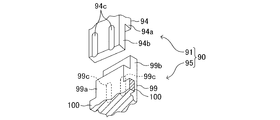
- the bell crank support member 40 is an integrally molded product made of resin. Therefore, the bell crank support member 40 is molded using a molding die 90 (metal mold) shown in FIGS.
- the molding die 90 is connected to a nozzle of an injection cylinder of an injection molding machine (not shown).
- the forming die 90 includes a first forming die 91 and a second forming die 95 that are opposed to each other in the horizontal direction and are relatively movable in the horizontal direction.
- a forming recess 93 is formed on a contact plane 92 that is a plane orthogonal to the horizontal direction of the first mold 91. Further, a molding convex portion 94 projects from the inner surface of the molding concave portion 93 toward the second molding die 95 side. As shown in the drawing, the molding convex portion 94 projects from the contact plane 92 toward the second molding die 95 side.
- the forming convex portion 94 has the shape shown in FIGS. 14 and 16 to 18 and has a wide width portion 94a constituting the base end portion and a narrow width portion 94b constituting the tip end portion. Further, as shown in FIGS.
- two guide protrusion forming grooves 94 c extending in the horizontal direction while being parallel to each other are formed in the outer surface of the forming protrusion 94.
- the second molding die 95 side end portion of the guide projection forming groove 94c is open at the second molding die 95 side end surface of the molding convex portion 94. Furthermore, the amount of depression of the guide projection forming groove 94c gradually increases from the side opposite to the second mold 95 toward the second mold 95 side.
- a forming convex portion 97 projects from a contact plane 96 which is a plane orthogonal to the horizontal direction of the second forming die 95.
- the molding convex portion 97 has a shape corresponding to the molding concave portion 93.
- a concave portion 98 for molding is provided in the contact plane 96.
- a molding convex part 99 projects from the inner surface of the molding concave part 98 toward the first mold 91 side.
- the forming convex portion 99 has the shape shown in FIGS. 14 and 16 to 18 and has a wide width portion 99a constituting the base end portion and a narrow width portion 99b constituting the tip end portion. Further, as shown in FIGS.
- two guide protrusion forming grooves 99 c extending in the horizontal direction while being parallel to each other are formed in the outer surface of the forming protrusion 99.
- the end portion of the guide projection forming groove 99c opposite to the first forming die 91 is terminated on the first forming die 91 side from the end surface of the forming convex portion 99 opposite to the first forming die 91. is doing.
- the amount of depression of the guide protrusion forming groove 99c gradually decreases from the first forming die 91 side toward the opposite side to the first forming die 91.
- the width (the vertical dimension in FIG. 15) of the molding convex portion 94 and the molding convex portion 99 is the same.
- a pair of connecting portions 100 that are connected to the inner surface of the molding recess 98 (the main body portion of the second molding die 95) project from the wide portion 99a.
- the molding convex portion 94 (narrow width portion 94b) of the first mold 91 is formed.
- the end surface on the second molding die 95 side contacts the inner surface of the molding recess 98.
- the end surface on the first molding die 91 side of the molding convex portion 99 (narrow width portion 99 b) of the second molding die 95 contacts the inner surface of the molding concave portion 93.
- the opposing surfaces of the forming convex portion 94 (wide portion 94a, narrow portion 94b) and the forming convex portion 99 (wide portion 99a, narrow portion 99b) come into contact with each other.
- a gap between the first molding die 91 and the second molding die 95 (for example, between the molding concave portion 93 and the molding convex portion 97, between the molding concave portion 98 and the molding convex portion 94, the guide projection Cavities are formed in the strip forming grooves 94c and the like.
- thermoplastic molten resin When thermoplastic molten resin is injected from the injection cylinder into the cavity with the first mold 91 and the second mold 95 closed, the molten resin flows into the entire cavity. After the mold 90 is cooled and the resin is solidified in the cavity, the first mold 91 and the second mold 95 are moved away from each other and the mold 90 is opened to be molded in the cavity. A bell crank support member 40 which is a resin molded product is obtained. As shown in FIGS. 14, 15, and 18, the arm receiving portion 46 is formed by the cavity formed in the outer peripheral portion of the molding convex portion 94 and the molding convex portion 99, and the pair of connection portions 100 Cutout portions 46a and 46b are formed.
- a pair of short distance side guide protrusions 49 are formed by the pair of guide protrusion forming grooves 94c, and a pair of long distance side guide protrusions 50 are formed by the pair of guide protrusion forming grooves 99c. .
- a part of the outline of the first mold 91 and a part of the outline of the second mold 95 are in line contact with each other. (See the bold line portion in FIG. 17).
- a parting line PL2 which is a linear protrusion with a small protrusion amount, is formed by a portion where the outlines are in line contact with each other (FIGS. 8 to 12, 14, and (See the bold line portion in FIG. 18).
- the parting line PL2 is formed on the surface of the arm receiving portion 46 while avoiding the guide protrusion 49a of the short distance side guide protrusion 49 and the guide protrusion 50a of the long distance side guide protrusion 50. ing.
- the front arm 23a and the rear surface 23b are respectively guided by the guide protrusion 49a of the short-distance side guide protrusion 49 and the guide protrusion 50a of the long-distance side guide protrusion 50, and the pressing arm 23 moves between the initial position and the operation position.
- the front surface 23a and the rear surface 23b do not come into contact with the parting line PL2 of the arm receiving portion 46 (plating applied to the surface thereof).
- a pair of short distance side guide protrusions 49 (guide protrusions 49a) and a pair of long distance side guide protrusions 50 (above and below the parting line PL1 on the front surface 23a and the rear surface 23b of the pressing arm 23.
- the pressing arm 23 can smoothly move relative to the bell crank support member 40 (arm receiving portion 46) between the initial position and the operation position. Further, when the pressing arm 23 moves (rotates), it is possible to eliminate the possibility that abnormal noise is generated between the pressing arm 23 (parting line PL1) and the arm receiving portion 46 (parting line PL2). .
- the protrusion distance of the short distance side guide protrusion 49 is gradually increased from the vehicle outer side toward the vehicle inner side, and the guide protrusion 49a is formed in the vicinity of the vehicle outer end portion, and the long distance
- the protruding amount of the side guide protrusion 50 is gradually increased from the vehicle inner side toward the vehicle outer side, and the guide protrusion 50a is formed in the vicinity of the vehicle inner end portion. Therefore, there are the following advantages compared with the comparative example shown in FIG. In the comparative example of FIG.
- the protrusion amount of the short distance side guide protrusion 49 ′ is gradually increased from the vehicle inner side toward the vehicle outer side, and the protrusion amount of the long distance side guide protrusion 50 ′ is increased from the vehicle outer side to the vehicle inner side.
- the first mold 91 ′ and the second mold 95 ′ have the illustrated cross-sectional shape.
- the parting line PL2 ′ is formed at the position shown in FIG.
- the guide protrusion 49a ′ is positioned in the vicinity of the vehicle inner end of the short distance side guide protrusion 49 ′. Is formed.
- the guide protrusion 50a ′ is desired to be formed in the vicinity of the vehicle outer end portion of the long-distance side guide protrusion 50 ′.
- the guide protrusion 50a ' cannot be formed in the vicinity of the vehicle outer end portion of the long-distance side guide protrusion 50'. Therefore, as shown in FIG. 19, the guide protrusion 50a ′ is formed at a position close to the vehicle inner end of the long-distance side guide protrusion 50 ′.
- the distance is close.
- the rear surface 23b of the pressing arm 23 is likely to come into contact with the parting line PL2 ′ of the long-distance guide protrusion 50 ′. Therefore, for example, when the shape of the short-distance guide ridge 49 ′ or the long-distance guide ridge 50 ′ changes from the initial shape (design shape) due to secular change, the rear surface 23b of the pressing arm 23 becomes the long-distance guide ridge.
- the guide protrusion 50a can be formed at a position where the distance between the parting line PL2 of the long-distance side guide protrusion 50 and the guide protrusion 50a becomes long. Therefore, for example, even if the shape of the short distance side guide protrusion 49 or the long distance side guide protrusion 50 changes from the initial shape (designed shape) due to secular change, the rear surface 23b of the pressing arm 23 remains on the long distance side guide protrusion 50. There is little risk of contact with the parting line PL2.
- the parting line PL2 ′ is formed at the vehicle inner end of the short-distance guide protrusion 49 ′.
- a guide projection 49a ′ is formed in the vicinity of the vehicle outer end of the short distance side guide protrusion 49 ′, and a parting line PL2 ′ is formed at the vehicle outer end of the long distance side guide protrusion 50 ′.
- the guide protrusion 50a ′ can be formed in the vicinity of the vehicle inner end portion of the long-distance side guide protrusion 50 ′.
- the present invention may be applied to a sliding vehicle door.
- the number of the short distance side guide protrusions 49 and the long distance side guide protrusions 50 provided in the arm receiving portion 46 may be one. Further, one of the short distance side guide protrusion 49 and the long distance side guide protrusion 50 may be omitted from the arm receiving portion 46.
- the positions of the guide protrusions 49a and 50a do not have to be near the ends of the short distance side guide protrusion 49 and the far distance side guide protrusion 50 opposite to the parting line PL2. However, it is preferable that the guide protrusions 49a and 50a be as far away as possible from the guide protrusion parting line PL2 provided with the guide protrusions 49a and 50a.
- Rotational support member 30 and bell crank support member 40 may be integrated into a single member.
- a reinforcing plate may be fixed to the inner surface of the outer panel 12 and the bell crank support member 40 may be fixed to the reinforcing plate. That is, the bell crank support member 40 may be indirectly fixed to the outer panel 12.
- the reinforcing plate (support member) is a resin product molded using a mold, and an arm through-hole (through-hole) through which the pressing arm 23 penetrates the reinforcing plate so as to be relatively movable is formed.
- a short-distance surface, a long-distance surface, a short-distance side guide ridge, and a long-distance side guide ridge may be formed on the inner peripheral surface of the through hole for use.
- the position of the parting line formed on the surface of the reinforcing plate is formed at a position away from the short distance side guide protrusion (guide protrusion) and the long distance side guide protrusion (guide protrusion).
- the member corresponding to the bell crank support member 40 does not include an arm through hole through which the pressing arm 23 passes.
Landscapes
- Engineering & Computer Science (AREA)
- Mechanical Engineering (AREA)
- Lock And Its Accessories (AREA)
Abstract
成形型を利用して成形された樹脂成形品である支持部材に形成されるパーティングラインによって、アウトサイドハンドルの回転動作が不円滑になったり、アウトサイドハンドルを回転させたときに異音が発生したりするおそれを無くすことが可能な車両用アウトサイドハンドル装置を提供する。支持部材の貫通孔の内面が、回転軸側に位置する近距離面と、近距離面よりも回転軸から離れた遠距離面と、を備え、近距離面と遠距離面との少なくとも一方に、押圧部の外周面を移動案内する案内突起を設け、支持部材の成形時に支持部材の外周面に形成されるパーティングラインの位置を案内突起からずらす。
Description
本発明は車両用アウトサイドハンドル装置に関する。
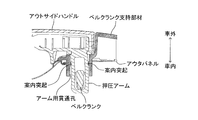
図21はアウトサイドハンドル装置を示している。このアウトサイドハンドル装置は、サイドドアである車両ドアのアウタパネルの車外側面に回転可能に支持されたアウトサイドハンドルを備えている。
アウタパネルには貫通孔が形成されている。アウタパネルの車内側面には、貫通孔と対向する軸受部材(図示略)が固定されている。
アウトサイドハンドルの長手方向の一端(図21の左側端部。図示略)は、貫通孔を車内方向に貫通しかつ軸受部材によって上下方向の回転軸まわりに回転可能に支持されている。アウトサイドハンドルは車両ドアに対して、この回転軸を中心に初期位置と、初期位置よりも車外側に位置する操作位置と、の間を回転可能である。さらにアウトサイドハンドルには、車内側に向かって延びる押圧アームが設けられている。
アウトサイドハンドルの長手方向の一端(図21の左側端部。図示略)は、貫通孔を車内方向に貫通しかつ軸受部材によって上下方向の回転軸まわりに回転可能に支持されている。アウトサイドハンドルは車両ドアに対して、この回転軸を中心に初期位置と、初期位置よりも車外側に位置する操作位置と、の間を回転可能である。さらにアウトサイドハンドルには、車内側に向かって延びる押圧アームが設けられている。
さらにアウタパネルにはベルクランク支持部材が装着されている。ベルクランク支持部材の一部はアウタパネルの車外側に位置しており、ベルクランク支持部材の残りの一部はアウタパネルの車内側に位置している。
ベルクランク支持部材には、ベルクランク支持部材を車両ドアの厚み方向(車内外方向)に貫通するアーム用貫通孔が形成されている。
アウトサイドハンドルの押圧アームは、ベルクランク支持部材のアーム用貫通孔を車内外方向(車両ドアの厚み方向)に相対移動可能に貫通している。
アウトサイドハンドルの押圧アームは、ベルクランク支持部材のアーム用貫通孔を車内外方向(車両ドアの厚み方向)に相対移動可能に貫通している。
図21に示すように、アーム用貫通孔の回転軸側の内面及び回転軸と反対側の内面の車内外方向の中央部には案内突起がそれぞれ突設されている。これらの案内突起には、押圧アームの回転軸側面と回転軸と反対側面がそれぞれスライド自在に接触している。そのため、アウトサイドハンドルが初期位置と操作位置との間を回転するとき、押圧アームは各案内突起によって案内されながらアーム用貫通孔(ベルクランク支持部材)に対して車内外方向に相対移動する。
ベルクランク支持部材には、アウタパネルの車内側に位置するベルクランクが回転可能に支持されている。ベルクランクは、初期位置と操作位置との間を回転可能であり、バネによって初期位置側へ回転付勢されている。
図21に示すようにベルクランクの一部は、アウトサイドハンドルの押圧アームと連係している。そのため、ベルクランクが初期位置に位置するときアウトサイドハンドルが初期位置に位置し、ベルクランクが操作位置に位置するときアウトサイドハンドルが操作位置に位置する。
図21に示すようにベルクランクの一部は、アウトサイドハンドルの押圧アームと連係している。そのため、ベルクランクが初期位置に位置するときアウトサイドハンドルが初期位置に位置し、ベルクランクが操作位置に位置するときアウトサイドハンドルが操作位置に位置する。
車両ドアは周知のロック装置を内蔵している。このロック装置は、車両ドアを車体に対して閉状態に保持するラッチ状態と、車両ドアが車体に対して回転するのを許容するアンラッチ状態と、に移行可能である。
ベルクランクとロック装置は連結レバーを介して互いに連係している。
ベルクランクとロック装置は連結レバーを介して互いに連係している。
アウトサイドハンドルが初期位置に位置するときベルクランクが初期位置に位置し、ロック装置はラッチ状態となる。一方、アウトサイドハンドルが操作位置に位置するときベルクランクが操作位置に位置し、ロック装置がアンラッチ状態となる。
(発明が解決しようとする課題)
ベルクランク支持部材は樹脂製であり、図22に示した成形型を利用して成形される。即ち、第一成形型と第二成形型を用いて成形される。
しかし、図示する第一成形型と第二成形型を用いてベルクランク支持部材を成形すると、第一成形型と第二成形型の接合面と同じ位置に案内突起が形成される。そのため、成形されたベルクランク支持部材の案内突起の表面に、突出量が微小な線形突条であるパーティングラインが形成されてしまう。
ベルクランク支持部材は樹脂製であり、図22に示した成形型を利用して成形される。即ち、第一成形型と第二成形型を用いて成形される。
しかし、図示する第一成形型と第二成形型を用いてベルクランク支持部材を成形すると、第一成形型と第二成形型の接合面と同じ位置に案内突起が形成される。そのため、成形されたベルクランク支持部材の案内突起の表面に、突出量が微小な線形突条であるパーティングラインが形成されてしまう。
従って、アウトサイドハンドルが初期位置と操作位置との間を回転するとき、押圧アームは各案内突起のパーティングラインに接触しながらアーム用貫通孔(ベルクランク支持部材)に対して車内外方向に相対移動することになる。
そのため、アウトサイドハンドルの回転動作が不円滑になったり、アウトサイドハンドルを回転させたときに押圧アームとベルクランク支持部材(パーティングライン)との間から異音が発生したりするおそれがある。
そのため、アウトサイドハンドルの回転動作が不円滑になったり、アウトサイドハンドルを回転させたときに押圧アームとベルクランク支持部材(パーティングライン)との間から異音が発生したりするおそれがある。
本発明は、成形型を利用して成形された樹脂成形品である支持部材に形成されるパーティングラインによって、アウトサイドハンドルの回転動作が不円滑になったり、アウトサイドハンドルを回転させたときに異音が発生したりするおそれを無くすことが可能な車両用アウトサイドハンドル装置を提供することを目的とする。
(課題を解決するための手段)
本発明は、車両ドアのアウタパネルに直接又は間接的に固定されかつ前記車両ドアの厚み方向に貫通する貫通孔を備える樹脂製の支持部材と、前記貫通孔を貫通しかつ所定の回転軸を中心にして前記支持部材に対して初期位置と該初期位置より車外側の操作位置との間を水平方向に相対回転可能である押圧部を有するアウトサイドハンドルと、前記アウタパネルの車内側に位置し、前記アウトサイドハンドルが前記初期位置から前記操作位置へ回転したときに、前記押圧部によって押圧されることにより回転して前記車両ドアに設けられたロック装置をラッチ状態からアンラッチ状態に移行させるベルクランクと、を備え、前記貫通孔の内面が、前記回転軸の軸線方向に見たときに該回転軸側に位置する近距離面と、該近距離面よりも前記回転軸から離れかつ前記近距離面と対向する遠距離面と、を備え、前記近距離面と前記遠距離面との少なくとも一方に、前記押圧部の外周面に接触することにより、前記アウトサイドハンドルが前記初期位置と前記操作位置との間を回転するときに前記押圧部を前記厚み方向に移動案内する案内突起を設け、前記支持部材の成形時に該支持部材の外周面に形成されるパーティングラインの位置を前記案内突起からずらした車両用アウトサイドハンドル装置である。
本発明は、車両ドアのアウタパネルに直接又は間接的に固定されかつ前記車両ドアの厚み方向に貫通する貫通孔を備える樹脂製の支持部材と、前記貫通孔を貫通しかつ所定の回転軸を中心にして前記支持部材に対して初期位置と該初期位置より車外側の操作位置との間を水平方向に相対回転可能である押圧部を有するアウトサイドハンドルと、前記アウタパネルの車内側に位置し、前記アウトサイドハンドルが前記初期位置から前記操作位置へ回転したときに、前記押圧部によって押圧されることにより回転して前記車両ドアに設けられたロック装置をラッチ状態からアンラッチ状態に移行させるベルクランクと、を備え、前記貫通孔の内面が、前記回転軸の軸線方向に見たときに該回転軸側に位置する近距離面と、該近距離面よりも前記回転軸から離れかつ前記近距離面と対向する遠距離面と、を備え、前記近距離面と前記遠距離面との少なくとも一方に、前記押圧部の外周面に接触することにより、前記アウトサイドハンドルが前記初期位置と前記操作位置との間を回転するときに前記押圧部を前記厚み方向に移動案内する案内突起を設け、前記支持部材の成形時に該支持部材の外周面に形成されるパーティングラインの位置を前記案内突起からずらした車両用アウトサイドハンドル装置である。
このように構成すれば、樹脂製の支持部材の貫通孔の近距離面と遠距離面との少なくとも一方に設けられた案内突起によって、アウトサイドハンドルの押圧部が移動案内される。
この案内突起の位置は、支持部材の成形時に支持部材の外周面に形成されるパーティングラインからずれている。そのため、押圧部がパーティングラインと干渉することはない。
そのため、アウトサイドハンドルの回転動作が不円滑になったり、アウトサイドハンドルを回転させたときに異音が発生したりするおそれを無くすことが可能である。
この案内突起の位置は、支持部材の成形時に支持部材の外周面に形成されるパーティングラインからずれている。そのため、押圧部がパーティングラインと干渉することはない。
そのため、アウトサイドハンドルの回転動作が不円滑になったり、アウトサイドハンドルを回転させたときに異音が発生したりするおそれを無くすことが可能である。
前記近距離面に前記厚み方向に延びる近距離側案内突条を設け、前記遠距離面に前記厚み方向に延びる遠距離側案内突条を設け、前記近距離側案内突条の一部に前記回転軸を中心とする小径円弧上に位置する前記案内突起である近距離側案内突起を形成し、かつ、前記近距離側案内突条の前記近距離側案内突起以外の部位を前記小径円弧の内周側に位置させ、前記遠距離側案内突条の一部に前記回転軸を中心とする大径円弧上に位置する前記案内突起である遠距離側案内突起を形成し、かつ、前記遠距離側案内突条の前記遠距離側案内突起以外の部位を前記大径円弧の外周側に位置させてもよい。
このように構成すれば、遠距離側案内突条のパーティングラインが形成される部位と案内突起との距離を長くすることが可能になる。従って、例えば経年変化によって近距離側案内突条(案内突起)や遠距離側案内突条(案内突起)の形状が初期形状(設計形状)から変化した場合に、押圧部が遠距離側案内突条のパーティングラインに接触するおそれを小さくできる。
前記近距離面及び前記遠距離面に、前記回転軸の軸線と平行な方向に離間した一対の前記案内突起をそれぞれ設けてもよい。
このように構成すると、支持部材の近距離面及び遠距離面に案内突起を一つずつ設ける場合と比べて、案内突起による押圧部の支持状態が安定する。
さらに、例えば押圧部が樹脂成形品であり、その外周面に水平方向に延びるパーティングラインが形成されている場合は、近距離面及び遠距離面の一対の案内突起を押圧部のパーティングラインの上下にそれぞれ位置させることにより、各案内突起と押圧部のパーティングラインとの干渉を防止できる。
さらに、例えば押圧部が樹脂成形品であり、その外周面に水平方向に延びるパーティングラインが形成されている場合は、近距離面及び遠距離面の一対の案内突起を押圧部のパーティングラインの上下にそれぞれ位置させることにより、各案内突起と押圧部のパーティングラインとの干渉を防止できる。
以下、本発明の実施形態について添付図面を参照しながら説明する。
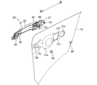
図1に示す車両ドア10は、車体(図示略)に対して上下方向の回転軸まわりに回転可能として支持されており、車体の側面に形成された開口部を開閉可能である。即ち、車両ドア10はサイドドアである。
車両ドア10の下半部を構成するドア本体11の車外側面は金属板からなるアウタパネル12により構成されている。
車両ドア10の内部には、その一部が車両ドア10の後端面において露出するロック装置13が設けられている。このロック装置13は、ラッチやポールを備える周知の構造である。ロック装置13は、車両ドア10の車内側面を構成するトリム(図示略)の上端面に上下方向にスライド自在に設けられたロックノブ14と連係している。さらにロック装置13は、アウタパネル12に回転可能に支持されたアウトサイドハンドル21を具備するアウトサイドハンドル装置20と連係している。
図1に示す車両ドア10は、車体(図示略)に対して上下方向の回転軸まわりに回転可能として支持されており、車体の側面に形成された開口部を開閉可能である。即ち、車両ドア10はサイドドアである。
車両ドア10の下半部を構成するドア本体11の車外側面は金属板からなるアウタパネル12により構成されている。
車両ドア10の内部には、その一部が車両ドア10の後端面において露出するロック装置13が設けられている。このロック装置13は、ラッチやポールを備える周知の構造である。ロック装置13は、車両ドア10の車内側面を構成するトリム(図示略)の上端面に上下方向にスライド自在に設けられたロックノブ14と連係している。さらにロック装置13は、アウタパネル12に回転可能に支持されたアウトサイドハンドル21を具備するアウトサイドハンドル装置20と連係している。
周知のように、車両ドア10が車体の開口部を閉じている場合にロックノブ14がロック位置(図示略)に位置するときは、ロック装置13はラッチが車体に固定されたストライカ(図示略)を把持するラッチ状態となる。この場合は、アウトサイドハンドル21を初期位置(図1、図2及び図7に実線で示す位置)から回転操作しても、ロック装置13はラッチ状態を維持する。一方、ロックノブ14がアンロック位置(図1の位置)に位置する場合は、アウトサイドハンドル21を初期位置から車外側へ回転させて操作位置(図7に仮想線で示す位置)へ移動させると、ロック装置13はラッチがストライカを解放するアンラッチ状態となる。従って、車両ドア10を車体に対して開方向に回転させることが可能になる。
続いてアウトサイドハンドル装置20の詳しい構造について説明する。
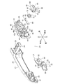
アウトサイドハンドル装置20は大きな構成要素としてアウトサイドハンドル21、回転支持部材30、ベルクランク支持部材40、パッド57、ベルクランク60、連係レバー70、捩じりコイルバネ75及び回転支持ピン79を具備している。
アウトサイドハンドル装置20は大きな構成要素としてアウトサイドハンドル21、回転支持部材30、ベルクランク支持部材40、パッド57、ベルクランク60、連係レバー70、捩じりコイルバネ75及び回転支持ピン79を具備している。
アウトサイドハンドル21は前後方向に延びる長尺状部材である。アウトサイドハンドル21は樹脂製であり、図示を省略した成形型を用いて成形される。さらにアウトサイドハンドル21の表面全体にはメッキが施されている。
アウトサイドハンドル21は、平面視略U字形をなす本体部22と、本体部22の後端部から車内側に向かって延びる押圧アーム23(押圧部)と、本体部22の前端部から車内側に向かって延びる回転支持アーム25と、を一体的に備えている。本体部22の車外側面は曲面によって構成されている。押圧アーム23の上面には係合溝24が凹設されている。回転支持アーム25の平面形状は略L字形である。回転支持アーム25には、回転支持アーム25を上下方向に貫通する回転軸27が固定されている。
アウトサイドハンドル21は、平面視略U字形をなす本体部22と、本体部22の後端部から車内側に向かって延びる押圧アーム23(押圧部)と、本体部22の前端部から車内側に向かって延びる回転支持アーム25と、を一体的に備えている。本体部22の車外側面は曲面によって構成されている。押圧アーム23の上面には係合溝24が凹設されている。回転支持アーム25の平面形状は略L字形である。回転支持アーム25には、回転支持アーム25を上下方向に貫通する回転軸27が固定されている。
押圧アーム23の水平面に沿う断面形状は図7及び図8に示す通りである。これらの図面から明らかなように押圧アーム23の平面形状は略円弧形である。押圧アーム23の前面23aは回転軸27を中心とする小径円弧に沿って形成されている。同様に、押圧アーム23の後面23bは回転軸27を中心とする大径円弧に沿って形成されている。そのため、後面23b(大径円弧)の曲率は前面23a(小径円弧)の曲率より小さい(曲率半径が大きい)。
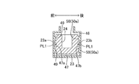
押圧アーム23の横断面形状は図13に示す通りである。図13から明らかなように押圧アーム23の横断面形状は略矩形である。押圧アーム23の前面23a及び後面23bの上下方向の中央部には、押圧アーム23の長手方向に沿って延びかつ突出量が微小な線形突条であるパーティングラインPL1が形成されている。このパーティングラインPL1は、上記成形型を利用した押圧アーム23の成形時に押圧アーム23の表面に形成されるものである。
さらに押圧アーム23の車内側端部の前方の角部23c及び後方の角部23dの断面形状はいずれも略円弧形である。但し、その曲率は角部23cより角部23dの方が大きい。
押圧アーム23の横断面形状は図13に示す通りである。図13から明らかなように押圧アーム23の横断面形状は略矩形である。押圧アーム23の前面23a及び後面23bの上下方向の中央部には、押圧アーム23の長手方向に沿って延びかつ突出量が微小な線形突条であるパーティングラインPL1が形成されている。このパーティングラインPL1は、上記成形型を利用した押圧アーム23の成形時に押圧アーム23の表面に形成されるものである。
さらに押圧アーム23の車内側端部の前方の角部23c及び後方の角部23dの断面形状はいずれも略円弧形である。但し、その曲率は角部23cより角部23dの方が大きい。
回転支持部材30は、平板状のベース板31と、ベース板31から前方に延びる支持部33と、を一体的に備えている。
ベース板31には雌ネジ孔32が設けられている。
支持部33は、共に略水平な天井板34及び底板35と、天井板34及び底板35の車内側縁部どうしを接続する側面板36と、を有している。天井板34及び底板35には互いに同軸をなす回転支持孔37がそれぞれ穿設されている。さらに支持部33の前部には逃がし孔38が形成されている。
ベース板31には雌ネジ孔32が設けられている。
支持部33は、共に略水平な天井板34及び底板35と、天井板34及び底板35の車内側縁部どうしを接続する側面板36と、を有している。天井板34及び底板35には互いに同軸をなす回転支持孔37がそれぞれ穿設されている。さらに支持部33の前部には逃がし孔38が形成されている。
アウトサイドハンドル21と回転支持部材30は、回転支持部材30の上下の回転支持孔37に対してアウトサイドハンドル21の回転軸27の上下両端部を回転可能に嵌合することにより互いに一体化する。
アウトサイドハンドル21と回転支持部材30が一体化すると、アウトサイドハンドル21は回転軸27及び回転支持孔37を中心にして回転支持部材30に対して相対回転可能となる。具体的には、図1、図2及び図7に実線で示す初期位置と、図7に仮想線で示す操作位置と、の間を水平方向に回転可能となる。さらに図7に示すように、回転支持アーム25の前端部が逃がし孔38を通り抜け、本体部22の前端部の車内側面がベース板31と対向する。
アウトサイドハンドル21と回転支持部材30が一体化すると、アウトサイドハンドル21は回転軸27及び回転支持孔37を中心にして回転支持部材30に対して相対回転可能となる。具体的には、図1、図2及び図7に実線で示す初期位置と、図7に仮想線で示す操作位置と、の間を水平方向に回転可能となる。さらに図7に示すように、回転支持アーム25の前端部が逃がし孔38を通り抜け、本体部22の前端部の車内側面がベース板31と対向する。
樹脂製の一体成形品であるベルクランク支持部材40(支持部材)は、中空状の本体部41を備えている。ベルクランク支持部材40の表面全体にはメッキが施されている。本体部41の車外側面は曲面によって構成されている。本体部41の車外側面の前部にはハンドル受容凹部41aが形成されている。
本体部41の車内側面の前部には前後一対の支持片42、43が車内側に向けて突設されている。前後の支持片42、43には互いに同軸をなす断面円形のピン支持孔44が穿設されている。
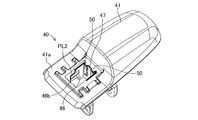
本体部41の車内側面の前部には、支持片42、43の直下に位置しかつ断面略矩形をなすアーム受容部46が車内側に向けて突設されている。さらにベルクランク支持部材40にはアーム受容部46を車幅方向(車内外方向)に貫通するアーム用貫通孔47(貫通孔)が形成されている。さらにアーム受容部46の上部と下部にはそれぞれ切欠部46a、46bが形成されている。
本体部41の車内側面の前部には前後一対の支持片42、43が車内側に向けて突設されている。前後の支持片42、43には互いに同軸をなす断面円形のピン支持孔44が穿設されている。
本体部41の車内側面の前部には、支持片42、43の直下に位置しかつ断面略矩形をなすアーム受容部46が車内側に向けて突設されている。さらにベルクランク支持部材40にはアーム受容部46を車幅方向(車内外方向)に貫通するアーム用貫通孔47(貫通孔)が形成されている。さらにアーム受容部46の上部と下部にはそれぞれ切欠部46a、46bが形成されている。
図6及び図9乃至図13等に示すように、アーム用貫通孔47の断面形状は略矩形である。アーム用貫通孔47の内面の前面は、回転軸27の軸線方向に見たときに当該内面の中で最も回転軸27側に位置する近距離面47aを構成している。一方、図13及び図15に示すように、アーム用貫通孔47の内面の後面は、回転軸27の軸線方向に見たときに当該内面の中で最も回転軸27から離れた位置に位置しかつ近距離面47aと前後方向に対向する遠距離面47bを構成している。
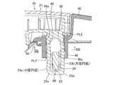
アーム用貫通孔47の近距離面47aには一対の近距離側案内突条49が上下に並べて突設されている。また、アーム用貫通孔47の遠距離面47bには一対の遠距離側案内突条50が上下に並べて突設されている。上側の近距離側案内突条49と遠距離側案内突条50は同じ高さに位置しており、下側の近距離側案内突条49と遠距離側案内突条50は同じ高さに位置している。図8及び図18(図18は模式図である)から明らかなように、上下の近距離側案内突条49の近距離面47aからの遠距離面47b側への突出量は、車外側から車内側に向かうにつれて徐々に大きくなっている。そして上下の近距離側案内突条49の車外側端部近傍が案内突起49a(近距離側案内突起)を構成している。図8及び図18から明らかなように、上下の遠距離側案内突条50の遠距離面47bからの近距離面47a側への突出量は、車内側から車外側に向かうにつれて徐々に大きくなっている。そして上下の遠距離側案内突条50の車内側端部近傍が案内突起50a(遠距離側案内突起)を構成している。
アーム用貫通孔47の近距離面47aには一対の近距離側案内突条49が上下に並べて突設されている。また、アーム用貫通孔47の遠距離面47bには一対の遠距離側案内突条50が上下に並べて突設されている。上側の近距離側案内突条49と遠距離側案内突条50は同じ高さに位置しており、下側の近距離側案内突条49と遠距離側案内突条50は同じ高さに位置している。図8及び図18(図18は模式図である)から明らかなように、上下の近距離側案内突条49の近距離面47aからの遠距離面47b側への突出量は、車外側から車内側に向かうにつれて徐々に大きくなっている。そして上下の近距離側案内突条49の車外側端部近傍が案内突起49a(近距離側案内突起)を構成している。図8及び図18から明らかなように、上下の遠距離側案内突条50の遠距離面47bからの近距離面47a側への突出量は、車内側から車外側に向かうにつれて徐々に大きくなっている。そして上下の遠距離側案内突条50の車内側端部近傍が案内突起50a(遠距離側案内突起)を構成している。
本体部41の車内側面の支持片43より後方に位置する部位は中空形状である。本体部41の前後方向の中央部の内面には円筒状の円筒部53が車内側に向けて突設されている。円筒部53の車内側端面には雌ネジ孔53aが形成されている。
さらにベルクランク支持部材40の車内側面の後部の内面には弾性変形可能な係止突起55が車内側に向けて突設されている。
さらにベルクランク支持部材40の車内側面の後部の内面には弾性変形可能な係止突起55が車内側に向けて突設されている。
ベルクランク支持部材40の本体部41の車内側面には樹脂製の薄板状部材であるパッド57が固定されている(図2、図6、7参照)。
パッド57は複数の孔を備えている。パッド57は、ベルクランク支持部材40の支持片42、43、アーム受容部46、係止突起55等の各突部を各孔を通してパッド57の車内側に突出させながら、本体部41の車内側面を塞いでいる。
さらにパッド57の前端部には係止突起58が突設されている。
パッド57は複数の孔を備えている。パッド57は、ベルクランク支持部材40の支持片42、43、アーム受容部46、係止突起55等の各突部を各孔を通してパッド57の車内側に突出させながら、本体部41の車内側面を塞いでいる。
さらにパッド57の前端部には係止突起58が突設されている。
互いに一体化したベルクランク支持部材40及びパッド57とアウトサイドハンドル21とは、押圧アーム23をアーム用貫通孔47に対して車外側から挿入しかつ本体部22の後端部をハンドル受容凹部41a内に位置させることにより互いに一体化される。
アウトサイドハンドル21とベルクランク支持部材40が一体化しかつアウトサイドハンドル21が回転支持部材30に対して初期位置に位置するとき、図1、図2及び図7の実線で示すように、本体部22の曲面からなる車外側面が本体部41の曲面からなる車外側面と連続する。
アウトサイドハンドル21とベルクランク支持部材40が一体化しかつアウトサイドハンドル21が回転支持部材30に対して初期位置に位置するとき、図1、図2及び図7の実線で示すように、本体部22の曲面からなる車外側面が本体部41の曲面からなる車外側面と連続する。
ベルクランク60は、本体部61と、被押圧突起66と、レバー支持部68と、を一体的に備えている。
図4及び図5(図4及び図5ではベルクランク60の一部を破断して示している)に示すように本体部61は、前後方向に延びる円筒部62を有している。円筒部62の内部は本体部61全体を前後方向に貫通するピン挿入孔63となっている。
被押圧突起66は、本体部61の下端部から車内側に向かって延びている。
レバー支持部68にはレバー支持凹部69が凹設されている。
図4及び図5(図4及び図5ではベルクランク60の一部を破断して示している)に示すように本体部61は、前後方向に延びる円筒部62を有している。円筒部62の内部は本体部61全体を前後方向に貫通するピン挿入孔63となっている。
被押圧突起66は、本体部61の下端部から車内側に向かって延びている。
レバー支持部68にはレバー支持凹部69が凹設されている。
図6に示す連係レバー70は、その基端部(下端部)がベルクランク60のレバー支持凹部69に固定状態で嵌合している。
捩じりコイルバネ75は一対の係止片76、77を備えている。
捩じりコイルバネ75はベルクランク60の円筒部62の外周面に装着されており、一方の係止片76はベルクランク60に係止されている。
捩じりコイルバネ75はベルクランク60の円筒部62の外周面に装着されており、一方の係止片76はベルクランク60に係止されている。
回転支持ピン79は、鍔部80と、鍔部80より小径の軸部81とを一体的に備えている。
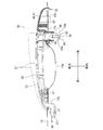
互いに一体化されたベルクランク60、連係レバー70及び捩じりコイルバネ75はベルクランク支持部材40に装着されている。支持片42と支持片43の間の空間に本体部61が挿入され、さらに図2、図5、図7及び図8に示すように被押圧突起66が押圧アーム23の係合溝24に嵌合している。捩じりコイルバネ75の係止片77はベルクランク支持部材40に係止されている(図5参照)。係止片77をベルクランク支持部材40に係止させると、捩じりコイルバネ75が弾性変形する。さらに回転支持ピン79の軸部81が支持片42のピン支持孔44、本体部61のピン挿入孔63及び支持片43のピン支持孔44に挿入されている。従って、ベルクランク60、連係レバー70及び捩じりコイルバネ75の一体物は、支持片42及び支持片43のピン支持孔44並びに回転支持ピン79を中心にしてベルクランク支持部材40に対して相対回転可能である。
上述のようにベルクランク60の被押圧突起66がアウトサイドハンドル21の押圧アーム23の係合溝24に嵌合するため、アウトサイドハンドル21の回転動作とベルクランク60(ベルクランク60、連係レバー70及び捩じりコイルバネ75の一体物)の回転動作は連動する。即ち、アウトサイドハンドル21が初期位置に位置するときにベルクランク60は図2及び図6に示す初期位置に位置し、アウトサイドハンドル21が操作位置に位置するときにベルクランク60は図示を省略した操作位置に位置する。アウトサイドハンドル21が初期位置と操作位置との間を回転するとき、前面23aと後面23bが案内突起49aと案内突起50aとによってそれぞれ移動案内されることにより、押圧アーム23がアーム受容部46に対して車内外方向に進退する。さらにアウトサイドハンドル21が操作位置に移動すると、押圧アーム23の角部23dが案内突起50aによって支持される。
さらに捩じりコイルバネ75の回転付勢力は、ベルクランク60を初期位置側に付勢する力である。そのため、アウトサイドハンドル21に対して捩じりコイルバネ75の付勢力以外の外力を及ぼさないとき、アウトサイドハンドル21及びベルクランク60は初期位置に保持される。
さらに捩じりコイルバネ75の回転付勢力は、ベルクランク60を初期位置側に付勢する力である。そのため、アウトサイドハンドル21に対して捩じりコイルバネ75の付勢力以外の外力を及ぼさないとき、アウトサイドハンドル21及びベルクランク60は初期位置に保持される。
このようにしてアウトサイドハンドル21、回転支持部材30、ベルクランク支持部材40、パッド57、ベルクランク60、連係レバー70、捩じりコイルバネ75及び回転支持ピン79をアッセンブリすることによりアウトサイドハンドル装置20が完成する。
アッセンブリされたアウトサイドハンドル装置20はアウタパネル12に対して装着される。
図1、図2及び図7に示すようにアウタパネル12には凹部構成部12aが形成されている。凹部構成部12aの車外側には凹部が形成されている。さらにアウタパネル12には第一貫通孔12b、第二貫通孔12c及び第三貫通孔12dがそれぞれ穿設されている。さらにアウタパネル12には円形貫通孔12e、12fが穿設されている。
図1、図2及び図7に示すようにアウタパネル12には凹部構成部12aが形成されている。凹部構成部12aの車外側には凹部が形成されている。さらにアウタパネル12には第一貫通孔12b、第二貫通孔12c及び第三貫通孔12dがそれぞれ穿設されている。さらにアウタパネル12には円形貫通孔12e、12fが穿設されている。
アウトサイドハンドル装置20をアウタパネル12に対して装着するには、まずアウトサイドハンドル装置20をアウタパネル12に対して車外側から接近させ、図7に示すように、回転支持アーム25の前端部を第一貫通孔12bを通してアウタパネル12の車内側に位置させる。
さらに図7に示すように、押圧アーム23、アーム受容部46、ベルクランク60、捩じりコイルバネ75及び回転支持ピン79を第二貫通孔12cを通してアウタパネル12の車内側に位置させ、係止突起58を第二貫通孔12cの前縁部に係合させる。
さらに図7に示すように、押圧アーム23、アーム受容部46、ベルクランク60、捩じりコイルバネ75及び回転支持ピン79を第二貫通孔12cを通してアウタパネル12の車内側に位置させ、係止突起58を第二貫通孔12cの前縁部に係合させる。
さらに図7に示すように、ベルクランク支持部材40の係止突起55を第三貫通孔12dを通してアウタパネル12の車内側へ移動させ、さらに係止突起55を弾性変形させながら第三貫通孔12dの後縁部に係止させる。このようにしてベルクランク支持部材40及びパッド57を第二貫通孔12c及び第三貫通孔12dに対して装着すると、アウトサイドハンドル装置20全体がアウタパネル12に対して仮止めされる。
アウトサイドハンドル装置20がアウタパネル12に仮止めされると、回転支持部材30の雌ネジ孔32が円形貫通孔12eと対向しかつベルクランク支持部材40の雌ネジ孔53aが円形貫通孔12fと対向する。
アウタパネル12の車内側からネジ85を円形貫通孔12eに挿入しかつネジ85を雌ネジ孔32に螺合させると、ベース板31がアウタパネル12の車外側面に接触した状態で回転支持部材30がアウタパネル12に対して固定される。また、アウタパネル12の車内側からネジ86を円形貫通孔12fに挿入しかつネジ86を雌ネジ孔53aに螺合させると、パッド57がアウタパネル12の車外側面に接触した状態でベルクランク支持部材40及びパッド57がアウタパネル12に対して固定される。
アウタパネル12の車内側からネジ85を円形貫通孔12eに挿入しかつネジ85を雌ネジ孔32に螺合させると、ベース板31がアウタパネル12の車外側面に接触した状態で回転支持部材30がアウタパネル12に対して固定される。また、アウタパネル12の車内側からネジ86を円形貫通孔12fに挿入しかつネジ86を雌ネジ孔53aに螺合させると、パッド57がアウタパネル12の車外側面に接触した状態でベルクランク支持部材40及びパッド57がアウタパネル12に対して固定される。
このようにしてアウトサイドハンドル装置20をアウタパネル12に固定したら、続いて図示を省略した金属製ロッドを連係レバー70とロック装置13に対してそれぞれ接続する。即ち、ロッドを介してロック装置13と連係レバー70を連係する。
ベルクランク60が初期位置に位置するときはロック装置13はラッチ状態となる。その一方で、ロックノブ14をアンロック位置に位置させた上でアウトサイドハンドル21を操作位置まで回転させることによりベルクランク60を操作位置に移動させるとロック装置13がアンラッチ状態となる。
ベルクランク60が初期位置に位置するときはロック装置13はラッチ状態となる。その一方で、ロックノブ14をアンロック位置に位置させた上でアウトサイドハンドル21を操作位置まで回転させることによりベルクランク60を操作位置に移動させるとロック装置13がアンラッチ状態となる。
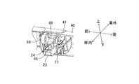
さらに、アウトサイドハンドル装置20をアウタパネル12に固定すると、図8及び図18に示すように、回転軸27を中心とする押圧アーム23の前面23a(前記小径円弧)がアーム用貫通孔47の近距離側案内突条49の案内突起49aにスライド可能に接触する。図示するように、近距離側案内突条49の案内突起49a以外の部位は前面23a(小径円弧)の内周側(前方)に位置している。また、アウトサイドハンドル装置20をアウタパネル12に固定すると、回転軸27を中心とする押圧アーム23の後面23b(前記大径円弧)がアーム用貫通孔47の遠距離側案内突条50の案内突起50aにスライド可能に接触する。図示するように、遠距離側案内突条50の案内突起50a以外の部位は後面23b(大径円弧)の外周側(後方)に位置している。
従って、アウトサイドハンドル21が初期位置と操作位置との間を回転するとき、押圧アーム23はアーム受容部46の近距離側案内突条49の案内突起49a及び遠距離側案内突条50の案内突起50aによって案内されながらアーム受容部46(本体部41)に対して車内外方向に相対移動する。しかも、押圧アーム23の前面23aと後面23bがそれぞれ二本の近距離側案内突条49(案内突起49a)と遠距離側案内突条50(案内突起50a)によって支持されているので、近距離側案内突条49(案内突起49a)と遠距離側案内突条50(案内突起50a)が一本ずつの場合と比べて、近距離側案内突条49(案内突起49a)と遠距離側案内突条50(案内突起50a)による押圧アーム23の支持状態が安定する。
従って、アウトサイドハンドル21が初期位置と操作位置との間を回転するとき、押圧アーム23はアーム受容部46の近距離側案内突条49の案内突起49a及び遠距離側案内突条50の案内突起50aによって案内されながらアーム受容部46(本体部41)に対して車内外方向に相対移動する。しかも、押圧アーム23の前面23aと後面23bがそれぞれ二本の近距離側案内突条49(案内突起49a)と遠距離側案内突条50(案内突起50a)によって支持されているので、近距離側案内突条49(案内突起49a)と遠距離側案内突条50(案内突起50a)が一本ずつの場合と比べて、近距離側案内突条49(案内突起49a)と遠距離側案内突条50(案内突起50a)による押圧アーム23の支持状態が安定する。
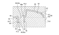
上述したようにベルクランク支持部材40は樹脂製の一体成形品である。そのためベルクランク支持部材40は図14乃至図18に示す成形型90(金型)を利用して成形される。成形型90は、図示を省略した射出成形機の射出シリンダのノズルに接続している。
成形型90は、互いに水平方向に対向しかつ水平方向に相対移動可能な第一成形型91と第二成形型95とを備えている。
第一成形型91の水平方向に対して直交する平面である接触平面92には成形用凹部93が形成されている。さらに成形用凹部93の内面からは成形用凸部94が第二成形型95側に向かって突出している。図示するように、成形用凸部94は接触平面92よりも第二成形型95側へ突出している。成形用凸部94は図14及び図16乃至図18に示す形状であり、その基端部を構成する広幅部94aと、その先端部を構成する狭幅部94bと、を有している。さらに図16乃至図18に示すように、成形用凸部94の外面には互いに平行をなしながら水平方向に延びる二本の案内突条成形用溝94cが凹設されている。図示するように案内突条成形用溝94cの第二成形型95側端部は、成形用凸部94の第二成形型95側端面において開放している。さらに案内突条成形用溝94cの凹み量は、第二成形型95と反対側から第二成形型95側に向かうにつれて徐々に大きくなっている。
第二成形型95の水平方向に対して直交する平面である接触平面96には成形用凸部97が突設されている。成形用凸部97は成形用凹部93と対応する形状である。接触平面96には成形用凹部98が凹設されている。さらに成形用凹部98の内面には成形用凸部99が第一成形型91側に向かって突設されている。成形用凸部99は図14及び図16乃至図18に示す形状であり、その基端部を構成する広幅部99aと、その先端部を構成する狭幅部99bと、を有している。さらに図16及び図18に示すように、成形用凸部99の外面には互いに平行をなしながら水平方向に延びる二本の案内突条成形用溝99cが凹設されている。図示するように案内突条成形用溝99cの第一成形型91と反対側の端部は、成形用凸部99の第一成形型91と反対側の端面より第一成形型91側において終端している。さらに案内突条成形用溝99cの凹み量は、第一成形型91側から第一成形型91と反対側に向かうにつれて徐々に小さくなっている。図15乃至図17に示すように成形用凸部94と成形用凸部99の幅(図15における上下寸法)は互いに同一である。さらに広幅部99aには成形用凹部98の内面(第二成形型95の本体部)に接続する接続部100が一対として突設されている。
第一成形型91と第二成形型95を閉じると(型締めすると)、図14、図17及び図18に示すように第一成形型91の成形用凸部94(狭幅部94b)の第二成形型95側端面が成形用凹部98の内面に接触する。さらに、第二成形型95の成形用凸部99(狭幅部99b)の第一成形型91側の端面が成形用凹部93の内面に接触する。また、成形用凸部94(広幅部94a、狭幅部94b)と成形用凸部99(広幅部99a、狭幅部99b)の互いの対向面どうしが接触する。さらに第一成形型91と第二成形型95との間の隙間(例えば、成形用凹部93と成形用凸部97との間、成形用凹部98と成形用凸部94との間、案内突条成形用溝94cなど)にはキャビティが形成される。
第一成形型91と第二成形型95を閉じた状態で上記キャビティに射出シリンダから熱可塑性の溶融樹脂を射出すると、溶融樹脂がキャビティ全体に流れ込む。
成形型90を冷却してキャビティ内で樹脂を固化させた後に、第一成形型91と第二成形型95を互いに離間する方向に移動させて成形型90を型開きすると、キャビティ内で成形された樹脂成形品であるベルクランク支持部材40が得られる。図14、図15及び図18に示したように、成形用凸部94及び成形用凸部99の外周部に形成されたキャビティによってアーム受容部46が形成され、かつ、一対の接続部100によって切欠部46a、46bが形成される。さらに、一対の案内突条成形用溝94cによって一対の近距離側案内突条49が形成され、かつ、一対の案内突条成形用溝99cによって一対の遠距離側案内突条50が形成される。
成形型90を冷却してキャビティ内で樹脂を固化させた後に、第一成形型91と第二成形型95を互いに離間する方向に移動させて成形型90を型開きすると、キャビティ内で成形された樹脂成形品であるベルクランク支持部材40が得られる。図14、図15及び図18に示したように、成形用凸部94及び成形用凸部99の外周部に形成されたキャビティによってアーム受容部46が形成され、かつ、一対の接続部100によって切欠部46a、46bが形成される。さらに、一対の案内突条成形用溝94cによって一対の近距離側案内突条49が形成され、かつ、一対の案内突条成形用溝99cによって一対の遠距離側案内突条50が形成される。
図17に示すように、第一成形型91と第二成形型95を閉じると第一成形型91の外形線の一部と第二成形型95の外形線の一部どうしが互いに線接触する(図17の太線部を参照)。
そしてアーム受容部46の表面には、この外形線どうしが線接触した部位によって、突出量が微小な線形突条であるパーティングラインPL2が形成される(図8乃至図12、図14、及び図18の太線部を参照)。これらの各図から明らかなように、パーティングラインPL2は近距離側案内突条49の案内突起49a及び遠距離側案内突条50の案内突起50aを避けながらアーム受容部46の表面に形成されている。
そしてアーム受容部46の表面には、この外形線どうしが線接触した部位によって、突出量が微小な線形突条であるパーティングラインPL2が形成される(図8乃至図12、図14、及び図18の太線部を参照)。これらの各図から明らかなように、パーティングラインPL2は近距離側案内突条49の案内突起49a及び遠距離側案内突条50の案内突起50aを避けながらアーム受容部46の表面に形成されている。
従って、前面23aと後面23bが近距離側案内突条49の案内突起49aと遠距離側案内突条50の案内突起50aとによってそれぞれ案内されながら押圧アーム23が初期位置と操作位置との間を回転するときに、前面23aと後面23bがアーム受容部46のパーティングラインPL2(の表面に施されたメッキ)に接触することがない。さらに図13に示すように、押圧アーム23の前面23a及び後面23bのパーティングラインPL1の上下に一対の近距離側案内突条49(案内突起49a)と一対の遠距離側案内突条50(案内突起50a)がそれぞれ接触するので、案内突起49aと案内突起50aはパーティングラインPL1と干渉しない。そのため、押圧アーム23はベルクランク支持部材40(アーム受容部46)に対して初期位置と操作位置との間を円滑に相対移動可能である。さらに押圧アーム23が移動(回転)するときに、押圧アーム23(パーティングラインPL1)とアーム受容部46(パーティングラインPL2)との間で異音が発生するおそれを無くすことが可能である。
さらにベルクランク支持部材40では、近距離側案内突条49の突出量を車外側から車内側に向かうにつれて徐々に大きくした上で車外側端部近傍に案内突起49aを形成し、かつ、遠距離側案内突条50の突出量を車内側から車外側に向かうにつれて徐々に大きくした上で車内側端部近傍に案内突起50aを形成している。そのため、図19に示す比較例と比べて以下の利点がある。
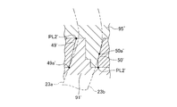
図19の比較例は、近距離側案内突条49’の突出量を車内側から車外側に向かうにつれて徐々に大きくしかつ遠距離側案内突条50’の突出量を車外側から車内側に向かうにつれて徐々に大きくした例である。この場合の第一成形型91’と第二成形型95’は図示の断面形状となる。この例ではパーティングラインPL2’は図19に示した位置に形成される。そのため、パーティングラインPL2’(の表面に施されたメッキ)と押圧アーム23(前面23a)との干渉を避けるべく、案内突起49a’を近距離側案内突条49’の車内側端部近傍に形成している。
図19の比較例では本来、遠距離側案内突条50’の車内側端部に形成されるパーティングラインPL2’(の表面に施されたメッキ)と押圧アーム23(後面23b)との干渉を避けるために、案内突起50a’を遠距離側案内突条50’の車外側端部近傍に形成したいところである。しかし、遠距離側案内突条50’の傾斜方向と後面23bの形状(後面23bを構成する大径円弧の中心である回転軸27の位置)とに起因して、(後面23bが接触するように)案内突起50a’を遠距離側案内突条50’の車外側端部近傍に形成することができない。そのため、図19に示すように、案内突起50a’を遠距離側案内突条50’の車内側端部に接近した位置に形成している。しかし、遠距離側案内突条50’の車内側端部にはパーティングラインPL2’が形成されているため、案内突起50a’と遠距離側案内突条50’のパーティングラインPL2’との距離が近くなっている。換言すると、押圧アーム23の後面23bが遠距離側案内突条50’のパーティングラインPL2’に接触し易くなっている。そのため、例えば経年変化によって近距離側案内突条49’や遠距離側案内突条50’の形状が初期形状(設計形状)から変化したときに、押圧アーム23の後面23bが遠距離側案内突条50’のパーティングラインPL2’(の表面に施されたメッキ)に接触するおそれがある。
これに対して本実施形態では、遠距離側案内突条50の傾斜方向と後面23bの形状(後面23bを構成する大径円弧の中心である回転軸27の位置)とに起因して、(後面23bが接触するように)案内突起50aを遠距離側案内突条50の車内側端部近傍に形成することが可能である。換言すると、遠距離側案内突条50のパーティングラインPL2と案内突起50aとの距離が長くなる位置に案内突起50aを形成することが可能である。従って、例えば経年変化によって近距離側案内突条49や遠距離側案内突条50の形状が初期形状(設計形状)から変化しても、押圧アーム23の後面23bが遠距離側案内突条50のパーティングラインPL2に接触するおそれは小さい。
図19の比較例は、近距離側案内突条49’の突出量を車内側から車外側に向かうにつれて徐々に大きくしかつ遠距離側案内突条50’の突出量を車外側から車内側に向かうにつれて徐々に大きくした例である。この場合の第一成形型91’と第二成形型95’は図示の断面形状となる。この例ではパーティングラインPL2’は図19に示した位置に形成される。そのため、パーティングラインPL2’(の表面に施されたメッキ)と押圧アーム23(前面23a)との干渉を避けるべく、案内突起49a’を近距離側案内突条49’の車内側端部近傍に形成している。
図19の比較例では本来、遠距離側案内突条50’の車内側端部に形成されるパーティングラインPL2’(の表面に施されたメッキ)と押圧アーム23(後面23b)との干渉を避けるために、案内突起50a’を遠距離側案内突条50’の車外側端部近傍に形成したいところである。しかし、遠距離側案内突条50’の傾斜方向と後面23bの形状(後面23bを構成する大径円弧の中心である回転軸27の位置)とに起因して、(後面23bが接触するように)案内突起50a’を遠距離側案内突条50’の車外側端部近傍に形成することができない。そのため、図19に示すように、案内突起50a’を遠距離側案内突条50’の車内側端部に接近した位置に形成している。しかし、遠距離側案内突条50’の車内側端部にはパーティングラインPL2’が形成されているため、案内突起50a’と遠距離側案内突条50’のパーティングラインPL2’との距離が近くなっている。換言すると、押圧アーム23の後面23bが遠距離側案内突条50’のパーティングラインPL2’に接触し易くなっている。そのため、例えば経年変化によって近距離側案内突条49’や遠距離側案内突条50’の形状が初期形状(設計形状)から変化したときに、押圧アーム23の後面23bが遠距離側案内突条50’のパーティングラインPL2’(の表面に施されたメッキ)に接触するおそれがある。
これに対して本実施形態では、遠距離側案内突条50の傾斜方向と後面23bの形状(後面23bを構成する大径円弧の中心である回転軸27の位置)とに起因して、(後面23bが接触するように)案内突起50aを遠距離側案内突条50の車内側端部近傍に形成することが可能である。換言すると、遠距離側案内突条50のパーティングラインPL2と案内突起50aとの距離が長くなる位置に案内突起50aを形成することが可能である。従って、例えば経年変化によって近距離側案内突条49や遠距離側案内突条50の形状が初期形状(設計形状)から変化しても、押圧アーム23の後面23bが遠距離側案内突条50のパーティングラインPL2に接触するおそれは小さい。
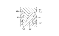
なお図20に示す比較例の断面形状の第一成形型91’’と第二成形型95’’とを用いれば、近距離側案内突条49’の車内側端部にパーティングラインPL2’を形成した上で近距離側案内突条49’の車外側端部近傍に案内突起49a’を形成し、かつ、遠距離側案内突条50’の車外側端部にパーティングラインPL2’を形成した上で遠距離側案内突条50’の車内側端部近傍に案内突起50a’を形成することが可能である。
しかし図20から明らかなように、この場合は第一成形型91’’と第二成形型95’’を成形した成形品(ベルクランク支持部材40)に対して型抜きできない。
そのため、この比較例はベルクランク支持部材40を実質的に成形できず実用性がない。
しかし図20から明らかなように、この場合は第一成形型91’’と第二成形型95’’を成形した成形品(ベルクランク支持部材40)に対して型抜きできない。
そのため、この比較例はベルクランク支持部材40を実質的に成形できず実用性がない。
以上、本発明の実施形態について説明したが、本発明は上記実施形態に限定されるべきものではない。
例えばサイドドア以外の車両ドア(例えばバックドア)に本発明を適用してもよい。
例えばサイドドア以外の車両ドア(例えばバックドア)に本発明を適用してもよい。
またスライド式の車両ドアに本発明を適用してもよい。
アーム受容部46に設ける近距離側案内突条49と遠距離側案内突条50の数はそれぞれ一つであってもよい。
また、アーム受容部46から近距離側案内突条49と遠距離側案内突条50との一方を省略してもよい。
また、アーム受容部46から近距離側案内突条49と遠距離側案内突条50との一方を省略してもよい。
案内突起49a、50aの位置は、近距離側案内突条49と遠距離側案内突条50のパーティングラインPL2と反対側の端部近傍である必要はない。但し、案内突起49a、50aが設けられた案内突条のパーティングラインPL2から、案内突起49a、50aをできる限り遠ざけて案内突条に設けるのが好ましい。
回転支持部材30とベルクランク支持部材40を一体化して一つの部材として構成してもよい。
アウタパネル12の車内側面に補強板(固定部材)を固定し、この補強板にベルクランク支持部材40を固定してもよい。即ち、ベルクランク支持部材40をアウタパネル12に対して間接的に固定してもよい。
さらに、この補強板(支持部材)を成形型を利用して成形した樹脂製品とし、この補強板に押圧アーム23が相対移動可能に貫通するアーム用貫通孔(貫通孔)を形成し、さらにアーム用貫通孔の内周面に近距離面、遠距離面、近距離側案内突条及び遠距離側案内突条を形成してもよい。この場合は、補強板の表面に形成されるパーティングラインの位置を、近距離側案内突条(案内突起)及び遠距離側案内突条(案内突起)から避けた位置に形成する。なお、この場合はベルクランク支持部材40に相当する部材は、押圧アーム23が貫通するアーム用貫通孔を具備しない。
さらに、この補強板(支持部材)を成形型を利用して成形した樹脂製品とし、この補強板に押圧アーム23が相対移動可能に貫通するアーム用貫通孔(貫通孔)を形成し、さらにアーム用貫通孔の内周面に近距離面、遠距離面、近距離側案内突条及び遠距離側案内突条を形成してもよい。この場合は、補強板の表面に形成されるパーティングラインの位置を、近距離側案内突条(案内突起)及び遠距離側案内突条(案内突起)から避けた位置に形成する。なお、この場合はベルクランク支持部材40に相当する部材は、押圧アーム23が貫通するアーム用貫通孔を具備しない。
Claims (3)
- 車両ドアのアウタパネルに直接又は間接的に固定されかつ前記車両ドアの厚み方向に貫通する貫通孔を備える樹脂製の支持部材と、
前記貫通孔を貫通しかつ所定の回転軸を中心にして前記支持部材に対して初期位置と該初期位置より車外側の操作位置との間を水平方向に相対回転可能である押圧部を有するアウトサイドハンドルと、
前記アウタパネルの車内側に位置し、前記アウトサイドハンドルが前記初期位置から前記操作位置へ回転したときに、前記押圧部によって押圧されることにより回転して前記車両ドアに設けられたロック装置をラッチ状態からアンラッチ状態に移行させるベルクランクと、
を備え、
前記貫通孔の内面が、前記回転軸の軸線方向に見たときに該回転軸側に位置する近距離面と、該近距離面よりも前記回転軸から離れかつ前記近距離面と対向する遠距離面と、を備え、
前記近距離面と前記遠距離面との少なくとも一方に、前記押圧部の外周面に接触することにより、前記アウトサイドハンドルが前記初期位置と前記操作位置との間を回転するときに前記押圧部を前記厚み方向に移動案内する案内突起を設け、
前記支持部材の成形時に該支持部材の外周面に形成されるパーティングラインの位置を前記案内突起からずらした、車両用アウトサイドハンドル装置。 - 請求項1に記載の車両用アウトサイドハンドル装置において、
前記近距離面に前記厚み方向に延びる近距離側案内突条を設け、
前記遠距離面に前記厚み方向に延びる遠距離側案内突条を設け、
前記近距離側案内突条の一部に前記回転軸を中心とする小径円弧上に位置する前記案内突起である近距離側案内突起を形成し、かつ、前記近距離側案内突条の前記近距離側案内突起以外の部位を前記小径円弧の内周側に位置させ、
前記遠距離側案内突条の一部に前記回転軸を中心とする大径円弧上に位置する前記案内突起である遠距離側案内突起を形成し、かつ、前記遠距離側案内突条の前記遠距離側案内突起以外の部位を前記大径円弧の外周側に位置させた、車両用アウトサイドハンドル装置。 - 請求項1又は2に記載の車両用アウトサイドハンドル装置において、
前記近距離面及び前記遠距離面に、前記回転軸の軸線と平行な方向に離間した一対の前記案内突起をそれぞれ設けた、
車両用アウトサイドハンドル装置。
Applications Claiming Priority (2)
| Application Number | Priority Date | Filing Date | Title |
|---|---|---|---|
| JP2015-191980 | 2015-09-29 | ||
| JP2015191980A JP6551114B2 (ja) | 2015-09-29 | 2015-09-29 | 車両用アウトサイドハンドル装置 |
Publications (1)
| Publication Number | Publication Date |
|---|---|
| WO2017056624A1 true WO2017056624A1 (ja) | 2017-04-06 |
Family
ID=58427399
Family Applications (1)
| Application Number | Title | Priority Date | Filing Date |
|---|---|---|---|
| PCT/JP2016/070389 Ceased WO2017056624A1 (ja) | 2015-09-29 | 2016-07-11 | 車両用アウトサイドハンドル装置 |
Country Status (2)
| Country | Link |
|---|---|
| JP (1) | JP6551114B2 (ja) |
| WO (1) | WO2017056624A1 (ja) |
Citations (2)
| Publication number | Priority date | Publication date | Assignee | Title |
|---|---|---|---|---|
| JP2000320195A (ja) * | 1999-05-14 | 2000-11-21 | Alpha Corp | 緩衝ストッパ部材付車両用ドアアウトサイドハンドル装置、および緩衝ストッパ部材 |
| JP4881776B2 (ja) * | 2007-03-29 | 2012-02-22 | 株式会社アルファ | ドアハンドル装置 |
-
2015
- 2015-09-29 JP JP2015191980A patent/JP6551114B2/ja active Active
-
2016
- 2016-07-11 WO PCT/JP2016/070389 patent/WO2017056624A1/ja not_active Ceased
Patent Citations (2)
| Publication number | Priority date | Publication date | Assignee | Title |
|---|---|---|---|---|
| JP2000320195A (ja) * | 1999-05-14 | 2000-11-21 | Alpha Corp | 緩衝ストッパ部材付車両用ドアアウトサイドハンドル装置、および緩衝ストッパ部材 |
| JP4881776B2 (ja) * | 2007-03-29 | 2012-02-22 | 株式会社アルファ | ドアハンドル装置 |
Also Published As
| Publication number | Publication date |
|---|---|
| JP2017066678A (ja) | 2017-04-06 |
| JP6551114B2 (ja) | 2019-07-31 |
Similar Documents
| Publication | Publication Date | Title |
|---|---|---|
| JP5610431B2 (ja) | 軸支構造、クリップ、および軸支構造の金型 | |
| JP6048125B2 (ja) | 車両ドアの固定装置 | |
| CN107313668B (zh) | 用于车辆的门限位连杆装置 | |
| JP2019059455A (ja) | 自動車のサンルーフのためのスライド装置 | |
| JP6493125B2 (ja) | 車両用アウトサイドハンドル装置 | |
| JP5171547B2 (ja) | ラッチ装置 | |
| JP2025145520A (ja) | 車両用両開き収容装置 | |
| JP6551114B2 (ja) | 車両用アウトサイドハンドル装置 | |
| JP4245528B2 (ja) | 車両用収納装置 | |
| JP2011231558A (ja) | 内装付属部材 | |
| JP2017197946A (ja) | ドアチェックリンク装置 | |
| JP4478103B2 (ja) | 車両用ドアハンドル及びその製造方法 | |
| JP2001207694A (ja) | 自動車のドアアウトサイドハンドル装置 | |
| JP2000346106A (ja) | スライド部材のストッパー装置 | |
| JP2006076344A (ja) | 車両用ロック装置 | |
| JP6271870B2 (ja) | 樹脂製ローラ軸の製造方法、成形用金型及びローラ軸 | |
| US20090239015A1 (en) | Resin injection molding apparatus and tubular resin member | |
| JP2707622B2 (ja) | 露出制御用羽根とその製造方法 | |
| JP4513614B2 (ja) | キー操作による駆動装置 | |
| JPH05185474A (ja) | 射出成形金型 | |
| JP6681202B2 (ja) | ドアチェック装置及びドアチェック装置の製造方法 | |
| JP7328676B2 (ja) | 成形装置及び成形製品の製造方法 | |
| JP3334114B2 (ja) | テープカセット | |
| JP4742341B2 (ja) | リング一体式表示盤の製造方法 | |
| JP6404247B2 (ja) | 車両用収納装置 |
Legal Events
| Date | Code | Title | Description |
|---|---|---|---|
| 121 | Ep: the epo has been informed by wipo that ep was designated in this application |
Ref document number: 16850801 Country of ref document: EP Kind code of ref document: A1 |
|
| NENP | Non-entry into the national phase |
Ref country code: DE |
|
| 122 | Ep: pct application non-entry in european phase |
Ref document number: 16850801 Country of ref document: EP Kind code of ref document: A1 |