WO2017056550A1 - 潤滑油基油の製造方法 - Google Patents
潤滑油基油の製造方法 Download PDFInfo
- Publication number
- WO2017056550A1 WO2017056550A1 PCT/JP2016/065811 JP2016065811W WO2017056550A1 WO 2017056550 A1 WO2017056550 A1 WO 2017056550A1 JP 2016065811 W JP2016065811 W JP 2016065811W WO 2017056550 A1 WO2017056550 A1 WO 2017056550A1
- Authority
- WO
- WIPO (PCT)
- Prior art keywords
- catalyst
- oil
- hydrocracking
- catalyst layer
- amorphous
- Prior art date
- Legal status (The legal status is an assumption and is not a legal conclusion. Google has not performed a legal analysis and makes no representation as to the accuracy of the status listed.)
- Ceased
Links
Images

Classifications
-
- C—CHEMISTRY; METALLURGY
- C10—PETROLEUM, GAS OR COKE INDUSTRIES; TECHNICAL GASES CONTAINING CARBON MONOXIDE; FUELS; LUBRICANTS; PEAT
- C10G—CRACKING HYDROCARBON OILS; PRODUCTION OF LIQUID HYDROCARBON MIXTURES, e.g. BY DESTRUCTIVE HYDROGENATION, OLIGOMERISATION, POLYMERISATION; RECOVERY OF HYDROCARBON OILS FROM OIL-SHALE, OIL-SAND, OR GASES; REFINING MIXTURES MAINLY CONSISTING OF HYDROCARBONS; REFORMING OF NAPHTHA; MINERAL WAXES
- C10G65/00—Treatment of hydrocarbon oils by two or more hydrotreatment processes only
- C10G65/02—Treatment of hydrocarbon oils by two or more hydrotreatment processes only plural serial stages only
- C10G65/12—Treatment of hydrocarbon oils by two or more hydrotreatment processes only plural serial stages only including cracking steps and other hydrotreatment steps
Definitions
- the present invention relates to a method for producing a lubricating base oil.
- atmospheric residual oil (Atmospheric Residue: AR) is obtained by atmospheric distillation of crude oil.
- a vacuum gas oil vacuum gas oil: VGO is obtained by vacuum distillation of this atmospheric residue (column bottom oil).
- Lubricating base oil (base oil for lubricating oil) is obtained by various reactions such as hydrocracking of these raw material oils.
- a catalyst containing an amorphous solid acid amorphous catalyst
- a catalyst containing a zeolite zeolite catalyst
- Patent Literature 1 below describes a hydrocracking catalyst containing amorphous silica alumina as a solid acid.
- Amorphous catalysts are excellent in naphthene isomerization and ring-opening activities.
- the activity of the amorphous catalyst is expressed at a temperature higher than that of the zeolite catalyst. That is, in hydrocracking using an amorphous catalyst, the amorphous catalyst must be heated at a higher temperature than when a zeolite catalyst is used. And, as the hydrocracking continues, the activity deteriorates due to coking or the like, so the temperature of the amorphous catalyst must be continuously raised to supplement the activity.
- the temperature of the amorphous catalyst reaches the upper limit of the heat resistant temperature of the reactor at a point earlier than when using a zeolite catalyst, and the hydrocracking is continued. It becomes difficult. That is, the lifetime of the amorphous catalyst is shorter than that of the zeolite catalyst.
- Zeolite catalysts are superior to amorphous catalysts in that hydrocracking activity is manifested at lower temperatures. Therefore, the catalyst life of the zeolitic catalyst is longer than that of the amorphous catalyst, and the amount of heat (energy) required for hydrocracking using the zeolitic catalyst is saved even when the amorphous catalyst is used.
- the present invention has been made in view of the above-described problems of the prior art, and provides a method for producing a lubricating base oil that extends the life of a hydrocracking catalyst and increases the viscosity index (VI) of the lubricating base oil.
- the purpose is to do.
- a feed oil containing an aromatic hydrocarbon is brought into contact with a first hydrocracking catalyst in the presence of hydrogen gas to obtain a first product oil.
- the zeolite contains a second hydrocracking catalyst containing an amorphous solid acid.
- a first catalyst layer containing a first hydrocracking catalyst and a second catalyst layer containing a second hydrocracking catalyst are fixed in one fixed bed reactor.
- the feed oil may be flowed to the first catalyst layer to obtain the first product oil
- the first product oil is flowed from the first catalyst layer to the second catalyst layer.
- a second product oil may be obtained.
- the raw material oil may be a vacuum gas oil.
- a method for producing a lubricating base oil that extends the life of the hydrocracking catalyst and increases the viscosity index (VI) of the lubricating base oil.
- FIG. 1 is a schematic cross-sectional view in the vertical direction of a reactor used in a method for producing a lubricating base oil according to an embodiment of the present invention.
- X, Y, and Z shown in FIG. 1 mean three coordinate axes that are orthogonal to each other.
- the Z axis is vertical and the X and Y axes are horizontal.
- the present invention is not limited to the following embodiment.
- a fixed bed reactor 10 shown in FIG. 1 is used.
- the fixed bed reactor 10 is a columnar reactor extending in the vertical direction Z.
- a first catalyst layer 1 and a second catalyst layer 2 are fixed in the fixed bed reactor 10.
- the first catalyst layer 1 and the second catalyst layer 2 are arranged in the vertical direction Z.
- the first catalyst layer 1 is disposed above the second catalyst layer 2.
- a region where the catalyst layers (1, 2) are not arranged in the fixed bed reactor 10 may be filled with a filler.
- the first catalyst layer 1 includes a first hydrocracking catalyst.
- the first catalyst layer 1 may be composed of only the first hydrocracking catalyst.
- the first hydrocracking catalyst contains zeolite.
- the first hydrocracking catalyst may be referred to as a zeolitic catalyst.
- the second catalyst layer 2 includes a second hydrocracking catalyst.
- the second catalyst layer 2 may be composed only of the second hydrocracking catalyst.
- the second hydrocracking catalyst contains an amorphous solid acid.
- the second hydrocracking catalyst may be referred to as an amorphous catalyst.
- the raw material oil 4 used for producing the lubricating base oil contains aromatic hydrocarbons.
- the raw material oil 4 may be, for example, a fraction obtained in a crude oil distillation process.
- the crude oil may be at least one selected from the group consisting of petroleum, condensate, synthetic crude oil derived from oil sand, and bitumen reformed oil, for example.
- the raw material oil 4 may be, for example, at least one selected from the group consisting of heavy oil (atmospheric residual oil), vacuum gas oil, vacuum residual oil, and solvent removal oil.
- Heavy oil (atmospheric residue) is obtained by atmospheric distillation of crude oil.
- Vacuum gas oil and vacuum residue are obtained by vacuum distillation of atmospheric residue.
- Solvent removal oil is obtained by solvent removal of the vacuum residue.
- the raw material oil 4 is a vacuum gas oil
- the properties of the vacuum gas oil may be as follows, for example. Density: 0.92 to 0.94. Aromatic hydrocarbon content: 45-60 mass%. Sulfur content: 2.2-3.0% by mass. Nitrogen content: 600-1200 mass ppm. Initial boiling point: 210-260 ° C. 5% distillation temperature: 300-330 ° C. 95% distillation temperature: 550-590 ° C. End point: 590-650 ° C.
- the manufacturing method of the lubricating base oil according to the present embodiment includes a first step and a second step.
- the raw material oil 4 is supplied from the upper part of the fixed bed reactor 10 into the fixed bed reactor 10.
- Hydrogen gas is also supplied into the fixed bed reactor 10.
- the raw material oil 4 is caused to flow to the first catalyst layer 1 in the presence of hydrogen gas. That is, in the first step, the feedstock 4 is brought into contact with the first hydrocracking catalyst in the first catalyst layer 1 to hydrocrack the feedstock 4.
- a first product oil 5A is obtained.
- the hydrocracking in the first step implies the production of naphthene by hydrogenation of aromatic hydrocarbons in the feedstock 4, and the production of isoparaffins by naphthene isomerization and ring opening. Hydrocracking depends on the acid nature of the first hydrocracking catalyst.
- the first product oil 5A obtained in the first step is caused to flow from the first catalyst layer 1 to the second catalyst layer 2 in the presence of hydrogen gas. That is, in the second step, the first product oil 5A is brought into contact with the second hydrocracking catalyst in the second catalyst layer 2 to hydrocrack the first product oil 5A.
- the second product oil 5B is obtained by hydrocracking the first product oil 5A.
- the hydrocracking in the second step implies the production of naphthene by hydrogenation of aromatic hydrocarbons in the first product oil 5A, and the production of isoparaffin by isomerization and ring opening of naphthene. Hydrocracking depends on the acid nature of the second hydrocracking catalyst.
- the second product oil 5B itself may be used as the lubricating base oil.
- a lubricating base oil may be obtained by hydrofinishing the second product oil 5B and subsequent vacuum distillation.
- the first process and the second process proceed continuously and automatically. Details of the first step and the second step are as follows.
- the raw material oil 4 supplied into the fixed bed reactor 10 flows downward due to gravity and comes into contact with the amorphous catalyst in the first catalyst layer 1.
- hydrocracking of the feedstock 4 occurs, and reaction heat of hydrocracking is generated.
- the first product oil 5 ⁇ / b> A heated by the reaction heat flows from the first catalyst layer 1 to the second catalyst layer 2. Therefore, the temperature of the second catalyst layer 2 tends to be higher than the temperature of the first catalyst layer 1.
- the hydrocracking of the feed oil 4 in the first catalyst layer 1 proceeds at a lower temperature than the hydrocracking of the first product oil 5A in the second catalyst layer 2.
- a zeolitic catalyst that is superior in activity at a lower temperature than the amorphous catalyst is disposed in the first catalyst layer 1. Therefore, the hydrocracking of the raw material oil 4 can sufficiently proceed in the low temperature first catalyst layer 1. In addition, the amount of heat (energy) required for hydrocracking in the first catalyst layer 1 can be saved by the excellent activity of the zeolite catalyst at a low temperature.
- the zeolitic catalyst is arranged in the first catalyst layer 1 which is at a lower temperature than the second catalyst layer 2, the naphthene isomerization and opening by the zeolitic catalyst is suppressed while suppressing the excessive decomposition of paraffin by the zeolitic catalyst to some extent. It is possible to cause a ring (formation of isoparaffin). That is, by daringly arranging the zeolite-based catalyst in the low temperature region (first catalyst layer 1), a decrease in the viscosity index of the lubricating base oil due to paralysis of paraffin is suppressed.
- the zeolite-based catalyst in the low temperature region (first catalyst layer 1), a decrease in the yield of the lubricating base oil due to paralysis of paraffin is also suppressed.
- the zeolitic catalyst is disposed in the second catalyst layer 2 having a higher temperature than the first catalyst layer 1, the decomposition of paraffin in the second catalyst layer 2 has priority over the isomerization and ring opening of naphthene. happenss. As a result, the viscosity index of the second product oil 5B decreases, and the yield of the lubricating base oil also decreases.
- the second step hydrogenation of aromatic hydrocarbons (generation of naphthene) and isomerization and ring opening of naphthene (generation of isoparaffin) in the first product oil 5A are further promoted by the amorphous catalyst. That is, the aromatic hydrocarbon and naphthene that remain without reacting in the first step are reacted in the second step, and isoparaffin is further generated. As a result, the viscosity index of the second product oil 5B increases.
- the temperature required to develop the activity of the amorphous catalyst is higher than that of the zeolite catalyst.
- the amorphous catalyst disposed in the second catalyst layer 2 is sufficiently heated by the first product oil 5 ⁇ / b> A supplied from the first catalyst layer 1.
- the activity of the amorphous catalyst is sufficiently expressed in the second catalyst layer 2.
- the temperature of the amorphous catalyst is set to compensate for the activity of the amorphous catalyst that deteriorates with time. I have to keep raising it.
- the temperature of the amorphous catalyst reaches the upper limit of the heat resistance temperature of the fixed bed reactor 10 at an early stage.
- hydrocracking (second step) with an amorphous catalyst is performed after hydrocracking (first step) with a zeolite-based catalyst having excellent activity.
- the load of the amorphous catalyst is reduced as compared with the conventional hydrocracking using only the amorphous catalyst. That is, in this embodiment, even if the temperature of the amorphous catalyst in the second step is lower than the conventional hydrocracking using only the amorphous catalyst, the second product oil 5B having a viscosity index equivalent to that of the conventional product is obtained. It can be obtained with the same yield as the conventional one.
- the time (life) until the temperature of the amorphous catalyst reaches the upper limit of the heat resistant temperature of the fixed bed reactor 10 is reduced. Can be extended. Similar to the case of the amorphous catalyst, in this embodiment, the load of the zeolite catalyst can be reduced as compared with the conventional hydrocracking using only the zeolite catalyst. As a result, even if the temperature of the zeolitic catalyst in the first step is lower than that of the conventional hydrocracking using only the zeolitic catalyst, the second product oil 5B having a viscosity index equivalent to the conventional one is equivalent to the conventional one. Yield.
- the temperature of the zeolite catalyst in the first step can be reduced. Therefore, the time (life) until the temperature of the zeolite catalyst reaches the upper limit of the heat resistant temperature of the fixed bed reactor 10 can be extended. From the above, in this embodiment, the life of the hydrocracking catalyst (zeolite-based catalyst and amorphous-based catalyst) is longer than before. In other words, when the hydrocracking according to the present embodiment is performed under the same reaction conditions (for example, reaction temperature) as in the conventional hydrocracking, the present embodiment has a sufficient viscosity over a longer time than in the past.
- the lubricant base oil having an index can be continuously produced with a substantially constant yield.
- 100 ⁇ V1 / (V1 + V2) is, for example, 5 to 75, 5 to 50, or 25 to 50. It may be.
- 100 ⁇ V1 / (V1 + V2) is 5 or more, compared with the case where only the second hydrocracking catalyst (amorphous catalyst) is used, the cracking activity of the entire catalyst is easily improved, and the same at a lower reaction temperature. Degradation rates tend to be achieved. This tendency is accompanied by an increase of 100 ⁇ V1 / (V1 + V2).
- V1 When 100 ⁇ V1 / (V1 + V2) is 50 or less, the viscosity index of the lubricating base oil tends to increase. This tendency is accompanied by a decrease of 100 ⁇ V1 / (V1 + V2).
- V1 may be rephrased as the volume of the first catalyst layer 1.
- V2 may be rephrased as the volume of the second catalyst layer 2. Even if 100 ⁇ V1 / (V1 + V2) is out of the above range, the effect of the present invention can be obtained.
- the temperature of the feedstock 4 may be 300 to 380 ° C., for example.
- the temperature of the raw material oil 4 may be adjusted in the above range in advance.
- the partial pressure of hydrogen gas in the reaction system (inside the fixed bed reactor 10) may be, for example, 5 to 20 MPa.
- the liquid hourly space velocity (LHSV) may be, for example, 0.1 to 1.5 h ⁇ 1 .
- the hydrogen / oil ratio (flow rate of hydrogen gas / flow rate of raw material oil 4) may be, for example, 300 to 2500 Nm 3 / m 3 .
- the temperature of the first catalyst layer 1 (first hydrocracking catalyst) may be, for example, 340 to 400 ° C.
- the temperature of the second catalyst layer 2 (second hydrocracking catalyst) may be, for example, 360 to 420 ° C.
- the fixed bed reactor 10 may be provided with a mechanism (control mechanism for various catalytic reactions) for controlling the various reaction conditions as described above.
- the control mechanism may be, for example, various means for heating and cooling each catalyst layer (1, 2), controlling the hydrogen partial pressure, venting, and adjusting the flow rate of the feed oil 4 and the second product oil 5B. .
- the cooling may be quenching by introducing hydrogen gas, for example.
- the shape of the fixed bed reactor 10 is not particularly limited, but may be, for example, a cylindrical shape. When the fixed bed reactor 10 is cylindrical, the fixed bed reactor 10 is excellent in pressure resistance.
- the first hydrocracking catalyst may contain a support and an active metal supported on the support.
- the first hydrocracking catalyst contains zeolite as a support.
- the zeolite contained in the first hydrocracking catalyst may be, for example, at least one selected from the group consisting of HY zeolite, ultra-stabilized Y type (USY type) zeolite, mordenite, and ⁇ zeolite. Of these, USY-type zeolite is preferable.
- USY-type zeolite can be obtained by ultra-stabilizing Y-type zeolite by at least either hydrothermal treatment or acid treatment.
- USY-type zeolite has a fine pore structure inherent to Y-type zeolite. This fine pore structure is a structure composed of micropores having a pore diameter of 2 nm or less. In addition to the fine pore structure, new pores having a pore diameter of 2 to 10 nm are formed in the USY-type zeolite.
- the average particle size of the USY-type zeolite may be, for example, 1.0 ⁇ m or less, or 0.5 ⁇ m or less.
- the silica / alumina molar ratio (molar ratio of silica to alumina) in the USY-type zeolite may be 10 to 200, 15 to 100, or 20 to 60.
- the first hydrocracking catalyst may further contain an amorphous metal oxide as a support in addition to zeolite.
- Amorphous metal oxides are alumina, silica, boria, zirconia, titania, magnesia, alumina-silica, alumina-boria, alumina-titania, alumina-zirconia, alumina-magnesia, alumina-silica-boria, alumina-silica-zirconia , Alumina-silica-titania, and at least one selected from the group consisting of alumina-titania-zirconia.
- the first hydrocracking catalyst may further contain an additive element such as phosphorus or chlorine.
- the first hydrocracking catalyst may contain USY-type zeolite and amorphous metal oxide as a support.
- the content of the USY zeolite in the carrier of the first hydrocracking catalyst may be 0.1 to 80% by mass, 10 to 80% by mass, or 30 to 70% by mass based on the total amount of the carrier.
- the content of the amorphous metal oxide in the support of the first hydrocracking catalyst may be 0.1 to 60% by mass based on the total amount of the support.
- the carrier for the first hydrocracking catalyst is produced, for example, by molding a composition containing USY-type zeolite and a binder and then firing the composition.
- a composition containing a raw material that becomes an amorphous composite metal oxide may be fired.
- the firing temperature of the composition may be, for example, 400 to 550 ° C, 470 to 530 ° C, or 490 to 530 ° C. By firing at such a firing temperature, sufficient solid acidity and mechanical strength are imparted to the carrier.
- the active metal contained in the first hydrocracking catalyst may be, for example, at least one metal selected from the group consisting of Group 6 elements, Group 8 elements, Group 9 elements, and Group 10 elements. . These elements belong to the periodic table of long-period elements based on IUPAC (International Pure Applied Chemistry Association) regulations.
- the active metal contained in the first hydrocracking catalyst may be at least one selected from the group consisting of platinum, palladium, rhodium, ruthenium, iridium, osmium, cobalt, nickel, molybdenum, tungsten, and iron, for example. .
- the active metal contained in the first hydrocracking catalyst may be at least one selected from the group consisting of platinum, palladium, nickel, cobalt, molybdenum and tungsten, for example.
- the active metal contained in the first hydrocracking catalyst is preferably at least one selected from the group consisting of cobalt, nickel, molybdenum and tungsten.
- the first hydrocracking catalyst may contain a plurality of types of active metals.
- the combination of active metals may be, for example, platinum-palladium, cobalt-molybdenum, nickel-molybdenum, nickel-cobalt-molybdenum, or nickel-tungsten.
- the active metal may be supported on the above-mentioned support by, for example, an impregnation method or an ion exchange method.
- the active metal content in the first hydrocracking catalyst may be, for example, 1.0 to 40 parts by mass, or 10 to 30 parts by mass with respect to 100 parts by mass of the support.
- the second hydrocracking catalyst may contain a support and an active metal supported on the support.
- the second hydrocracking catalyst contains an amorphous solid acid as a support.
- Non-crystalline solid acids contained in the second hydrocracking catalyst are, for example, silica-alumina, silica-zirconia, alumina-boria, silica-titania, silica-magnesia, kaolinite, aluminophosphate, silica aluminophos. It may be at least one selected from the group consisting of fate and alumina-silica-zirconia.
- the second hydrocracking catalyst does not contain zeolite as a support.
- the carrier for the second hydrocracking catalyst is produced, for example, by molding a mixture containing an amorphous solid acid and a binder and then firing the mixture.
- the content of the solid acid in the carrier may be, for example, 5 to 90% by mass, or 8 to 70% by mass based on the total amount of the carrier.
- the binder may be at least one selected from the group consisting of alumina (such as boehmite), silica, silica alumina, titania, and magnesia.
- the binder is preferably alumina.
- the content of the binder in the carrier may be, for example, 10 to 90% by mass, or 20 to 80% by mass based on the total amount of the carrier.
- the firing temperature of the mixture containing the amorphous solid acid and the binder may be, for example, 300 to 600 ° C, 400 to 550 ° C, or 430 to 500 ° C.
- the active metal contained in the second hydrocracking catalyst may be at least one selected from the group consisting of platinum, palladium, nickel, cobalt, molybdenum and tungsten, for example.
- the active metal contained in the second hydrocracking catalyst is preferably at least one selected from the group consisting of cobalt, nickel, molybdenum and tungsten, for example.
- the second hydrocracking catalyst may contain a plurality of types of active metals.
- the combination of active metals may be, for example, platinum-palladium, cobalt-molybdenum, nickel-molybdenum, nickel-cobalt-molybdenum, or nickel-tungsten.
- the active metal may be supported on the above-mentioned support by, for example, an impregnation method or an ion exchange method.
- the active metal content in the first hydrocracking catalyst may be, for example, 1.0 to 40 parts by mass, or 10 to 30 parts by mass with respect to 100 parts by mass of the support.
- the support for the first hydrocracking catalyst may be molded, for example.
- the shape of the shaped carrier may be, for example, spherical, cylindrical, columnar, or disk-shaped.
- the shape of the carrier may be a cylindrical shape or a column shape having a three-leaf type or a four-leaf type cross section.
- the carrier molding method may be, for example, extrusion molding or tableting molding.
- the support of the second hydrocracking catalyst may be formed in the same manner as the support of the first hydrocracking catalyst.
- the shape of the carrier of the second hydrocracking catalyst and the molding method may be the same as in the case of the carrier of the first hydrocracking catalyst.
- the first catalyst layer and the second catalyst layer may be aligned in the horizontal direction.
- the first catalyst layer and the second catalyst layer may not be disposed in the same fixed bed reactor.
- the first product oil obtained in the first fixed bed reactor is adiabatic. It is supplied to the second fixed bed reactor in which the second catalyst layer is arranged via the transport path (pipe) having heat retention, and the second step is carried out in the second fixed bed reactor. May be. You may implement beforehand the demetallation of feedstock, or the hydrorefining (for example, hydrodesulfurization and hydrodenitrogenation) of feedstock.
- Example 1 The first catalyst layer 1 and the second catalyst layer 2 were fixed in a tower-like fixed bed reactor 10 as shown in FIG.
- the first catalyst layer 1 and the second catalyst layer 2 were arranged in the vertical direction Z.
- the first catalyst layer 1 was disposed above the second catalyst layer 2.
- the first catalyst layer 1 was composed only of a commercially available zeolite-based catalyst (first hydrocracking catalyst).
- the zeolite-based catalyst contained USY type zeolite as a carrier.
- the content of USY-type zeolite was 50% by mass with respect to the entire zeolite-based catalyst.
- the number of moles of silica constituting the USY-type zeolite and [SiO 2], the ratio of the moles of alumina constituting the USY type zeolite [Al 2 O 3] [SiO 2] / [Al 2 O 3] at 30 there were.
- the average particle size of the zeolitic catalyst was 0.4 ⁇ m.
- the zeolite-based catalyst contained nickel and tungsten as active metals supported on the support.
- the second catalyst layer 2 was composed only of a commercially available amorphous catalyst (second hydrocracking catalyst).
- the amorphous catalyst contained an amorphous solid acid (alumina-silica-zirconia) as a support.
- the amorphous catalyst contained nickel and tungsten as active metals supported on the carrier.
- the amorphous catalyst did not contain zeolite.
- the ratio V1 (%) of the volume of the first catalyst layer 1 to the total volume (100%) of the volume of the first catalyst layer 1 and the volume of the second catalyst layer 2 was adjusted to the values shown in Table 1 below.
- the ratio V2 (%) of the volume of the second catalyst layer 2 to the total (100%) of the volume of the first catalyst layer 1 and the volume of the second catalyst layer 2 was adjusted to the values shown in Table 1 below.
- vacuum gas oil that had been hydrodesulfurized in advance was used.
- the vacuum gas oil continued to flow from the upper part of the fixed bed reactor 10 into the fixed bed reactor 10 and continued to pass through the first catalyst layer 1 and the second catalyst layer 2. Further, the hydrogen gas was continuously supplied into the fixed bed reactor 10.
- hydrocracking first step and two steps was continued to obtain first product oil 5A and second product oil 5B.
- the oil flowing into the second catalyst layer 2 from the first catalyst layer 1 corresponds to the first product oil 5A.
- the oil flowing out from the second catalyst layer 2 to the lower part of the fixed bed reactor 10 corresponds to the second product oil 5B.
- the atmospheric pressure (hydrogen gas pressure) in the fixed bed reactor 10 was adjusted to 11.0 MPa.
- Total LHSV was adjusted to 0.55 h- 1 .
- the reaction temperature was continuously adjusted over time so that the decomposition rate was maintained at a value close to the target value (65% by mass). That is, the temperature of each of the first catalyst layer 1 and the second catalyst layer 2 was continuously adjusted over time so that the decomposition rate was maintained at a value close to the target value (65% by mass).
- the reaction temperature is a value obtained by averaging the reaction temperature of the first catalyst layer 1 and the reaction temperature of the second catalyst layer 2 by weight of each catalyst layer. That is, the reaction temperature is the weight average temperature (WABT) of the catalyst bed.
- the decomposition rate is defined by the following formula 1.
- Example 1 The reaction temperature of Example 1 is shown in Table 1 below.
- the reaction temperatures shown in Table 1 below are reaction temperatures 14 days after the start of oil passing (supply of reduced pressure gas oil into the fixed bed reactor 10).
- the decomposition rate of Example 1 is shown in Table 1 below.
- the decomposition rate shown in following Table 1 is a decomposition rate in 14 days after starting oil passing.
- Rc ⁇ (M1-M2) / M1 ⁇ ⁇ 100 (1)
- Rc is a decomposition rate (unit: mass%).
- M1 is the mass of the fraction contained in the vacuum gas oil (raw oil 4) having a boiling point of 360 ° C. or higher.
- M2 is the mass of the fraction contained in the product oil (second product oil 5B) having a boiling point of 360 ° C. or higher.
- the decomposition rate Rc indicates the degree of reduction of heavy components (fraction having a boiling point of 360 ° C. or higher) contained in the vacuum gas oil (raw oil 4).
- a light fraction having a boiling point of less than 360 ° C. and a heavy fraction having a boiling point of 360 ° C. or higher were obtained by fractionation of the product oil.
- the viscosity index (VI) of this heavy fraction was measured. Table 1 below shows VI of the bottom oil obtained in Example 1.
- the tower bottom oil is used as a raw material for lubricating base oil.
- Example 2 and 3 In Examples 2 and 3, the volume ratios of the first catalyst layer 1 and the second catalyst layer 2 were adjusted to the values shown in Table 1 below. Except for these matters, hydrocracking of the vacuum gas oil was continued in the same manner as in Example 1 to obtain the product oils of Examples 2 and 3, respectively. Table 1 below shows the reaction temperature, decomposition rate, and VI of the bottom oil measured in the same manner as in Example 1.
- Comparative Example 1 In Comparative Example 1, both the first catalyst layer 1 and the second catalyst layer 2 were composed only of the zeolite catalyst. In Comparative Example 1, the volume ratios of the first catalyst layer 1 and the second catalyst layer 2 were adjusted to the values shown in Table 1 below. Except for these matters, hydrocracking of the vacuum gas oil was continued in the same manner as in Example 1 to obtain the product oil of Comparative Example 1. Table 1 below shows the reaction temperature, decomposition rate, and VI of the bottom oil measured in the same manner as in Example 1.
- Comparative Example 2 In Comparative Example 2, both the first catalyst layer 1 and the second catalyst layer 2 were composed only of the amorphous catalyst. In Comparative Example 2, the volume ratios of the first catalyst layer 1 and the second catalyst layer 2 were adjusted to the values shown in Table 1 below. Except for these matters, hydrocracking of the vacuum gas oil was continued in the same manner as in Example 1 to obtain a product oil of Comparative Example 2. The reaction temperature, decomposition rate, and VI of the bottom oil measured in the same manner as in Example 1 are shown in Table 1 below.
- Comparative Example 3 In Comparative Example 3, the first catalyst layer 1 was composed only of the amorphous catalyst. In Comparative Example 3, the second catalyst layer 2 was composed only of the zeolite catalyst. In Comparative Example 3, the volume ratios of the first catalyst layer 1 and the second catalyst layer 2 were adjusted to the values shown in Table 1 below. Except for these matters, hydrocracking of the vacuum gas oil was continued in the same manner as in Example 1 to obtain the product oil of Comparative Example 3. Table 1 below shows the reaction temperature, decomposition rate, and VI of the bottom oil measured in the same manner as in Example 1.
- the catalyst life of each of Examples 1 to 3 and Comparative Examples 1 to 3 is shown in Table 1 below.
- the catalyst life is the number of days until the reaction temperature reaches the upper limit (420 ° C.) of the heat resistance temperature of the fixed bed reactor 10 from the time when oil passing is started.
- the catalyst life was estimated by the following method. First, the above hydrocracking reaction was continued for a predetermined period (3 to 6 months), and the reaction rate was measured over time. The overall deterioration rate of the first catalyst layer 1 and the second catalyst layer 2 was calculated from the time course of the measured reaction rate. The transition of reaction temperature was obtained by simulation of hydrocracking reaction based on this deterioration rate. From the transition of the reaction temperature, the time for the reaction temperature to reach 420 ° C. was estimated.
- the VI described in Table 1 is preferably 130 or more, and more preferably 140 or more.
- the catalyst life shown in Table 1 is preferably 2 years or longer.
Landscapes
- Chemical & Material Sciences (AREA)
- Oil, Petroleum & Natural Gas (AREA)
- Engineering & Computer Science (AREA)
- Chemical Kinetics & Catalysis (AREA)
- General Chemical & Material Sciences (AREA)
- Organic Chemistry (AREA)
- Production Of Liquid Hydrocarbon Mixture For Refining Petroleum (AREA)
Abstract
水素化分解触媒の寿命を延ばし、且つ潤滑油基油の粘度指数を高める潤滑油基油の製造方法が提供される。潤滑油基油の製造方法は、芳香族炭化水素を含有する原料油(4)を、水素ガスの存在下で第一水素化分解触媒(1)に接触させて、第一生成油(5A)を得る第一工程と、第一生成油(5A)を、水素ガスの存在下で第二水素化分解触媒(2)に接触させて、第二生成油(5B)を得る第二工程と、を備え、第一水素化分解触媒(1)が、ゼオライトを含有し、第二水素化分解触媒(2)が、非晶質の固体酸を含有する。
Description
本発明は、潤滑油基油の製造方法に関する。
石油の精製過程では、原油の常圧蒸留によって、常圧残油(Atmospheric Residue: AR)が得られる。この常圧残油(塔底油)の減圧蒸留によって、減圧軽油(Vacuum Gas Oil: VGO)が得られる。これらの原料油の水素化分解等の諸反応により、潤滑油基油(潤滑油用の基油)が得られる。水素化分解触媒としては、例えば、非晶質の固体酸を含有する触媒(アモルファス系触媒)、及びゼオライトを含有する触媒(ゼオライト系触媒)が知られている。例えば、下記特許文献1には、固体酸として非晶質のシリカアルミナを含有する水素化分解触媒が記載されている。
芳香族炭化水素を含む原料油(例えば減圧軽油)を水素化分解触媒に接触させると、芳香族炭化水素の水素化により、ナフテンが生成し、ナフテンの異性化及び開環により、粘度指数(VI)が高いイソパラフィンを含有する生成油が得られる。イソパラフィンを含有する生成油の分留によって得られる塔底油は、潤滑油基油の原料として利用される。
アモルファス系触媒は、ナフテンの異性化及び開環の活性に優れる。しかし、アモルファス系触媒の活性は、ゼオライト系触媒の活性よりも高い温度で発現する。つまり、アモルファス系触媒を用いた水素化分解では、ゼオライト系触媒を用いる場合よりも高い温度でアモルファス系触媒を加熱しなければならない。そして、水素化分解を継続するほど、コーキング(coking)等により活性が劣化するので、活性を補うためにアモルファス系触媒の温度を上げ続けなければならない。その結果、アモルファス系触媒を用いた水素化分解では、ゼオライト系触媒を用いる場合よりも早い時点で、アモルファス系触媒の温度が反応器の耐熱温度の上限値に到達し、水素化分解の継続が困難になる。つまり、アモルファス系触媒の寿命は、ゼオライト系触媒の寿命よりも短い。
ゼオライト系触媒は、水素化分解の活性がより低温で発現する点において、アモルファス系触媒よりも優れている。したがって、ゼオライト系触媒の触媒寿命は、アモルファス系触媒の触媒寿命よりも長く、ゼオライト系触媒を用いる水素化分解に要する熱量(エネルギー)は、アモルファス系触媒を用いる場合によりも節約される。
しかしながら、ゼオライト系触媒を用いた水素化分解では、アモルファス系触媒を用いた水素化分解と比較して、パラフィンの水素化分解が、ナフテンの異性化及び開環よりも優先して起こり易い。したがって、ゼオライト系触媒を用いた水素化分解では、アモルファス系触媒を用いる場合に比べて、ナフテンの異性化及び開環が起き難く、イソパラフィンが生成し難い。その結果、ゼオライト系触媒を用いて得られる生成油の粘度指数は、アモルファス系触媒を用いて得られる生成油の粘度指数よりも低い。
以上のように、従来の潤滑油基油の製造方法では、水素化分解触媒の長い寿命と、潤滑油基油の高い粘度指数と、を両立させることは困難である。
本発明は、上記従来技術の有する課題に鑑みてなされたものであり、水素化分解触媒の寿命を延ばし、且つ潤滑油基油の粘度指数(VI)を高める潤滑油基油の製造方法を提供することを目的とする。
本発明の一側面に係る潤滑油基油の製造方法は、芳香族炭化水素を含有する原料油を、水素ガスの存在下で第一水素化分解触媒に接触させて、第一生成油を得る第一工程と、第一生成油を、水素ガスの存在下で第二水素化分解触媒に接触させて、第二生成油を得る第二工程と、を備え、第一水素化分解触媒が、ゼオライトを含有し、第二水素化分解触媒が、非晶質の固体酸を含有する。
本発明の一側面においては、第一水素化分解触媒の体積がV1であり、第二水素化分解触媒の体積がV2であるとき、100・V1/(V1+V2)が、5~50であってよい。
本発明の一側面においては、第一水素化分解触媒を含む第一触媒層と、第二水素化分解触媒を含む第二触媒層と、が、一つの固定床型反応器内に固定されていてよく、第一工程では、原料油を第一触媒層へ流して、第一生成油を得てよく、第二工程では、第一生成油を第一触媒層から第二触媒層へ流して、第二生成油を得てよい。
本発明の一側面においては、原料油が、減圧軽油であってよい。
本発明によれば、水素化分解触媒の寿命を延ばし、且つ潤滑油基油の粘度指数(VI)を高める潤滑油基油の製造方法が提供される。
以下、図1を参照しながら、本発明の好適な実施形態について説明する。図1において、同等の構成要素には同等の符号を付す。図1に示すX,Y及びZは、互いに直交する3つの座標軸を意味する。Z軸は鉛直であり、X軸及びY軸は水平である。本発明は下記実施形態に限定されるものではない。
本実施形態に係る潤滑油基油の製造方法では、図1に示す固定床型反応器10を用いる。固定床型反応器10は、鉛直方向Zに延びる塔状の反応器である。固定床型反応器10内には、第一触媒層1及び第二触媒層2が固定されている。第一触媒層1及び第二触媒層2は鉛直方向Zに並んでいる。第一触媒層1は、第二触媒層2の上方に配置されている。固定床型反応器10内において上記の触媒層(1,2)が配置されていない領域には、充填材が充填されていてよい。
第一触媒層1は、第一水素化分解触媒を含む。第一触媒層1は、第一水素化分解触媒のみから構成されていてよい。第一水素化分解触媒は、ゼオライトを含有する。以下では、第一水素化分解触媒を、ゼオライト系触媒と記す場合がある。第二触媒層2は、第二水素化分解触媒を含む。第二触媒層2は、第二水素化分解触媒のみから構成されていてよい。第二水素化分解触媒は、非晶質(アモルファス)の固体酸を含有する。以下では、第二水素化分解触媒を、アモルファス系触媒と記す場合がある。
潤滑油基油の製造に用いる原料油4は、芳香族炭化水素を含有する。原料油4は、例えば、原油の蒸留過程で得られる留分であってよい。原油は、例えば、石油、コンデンセート、オイルサンド由来の合成原油、及びビチューメン改質油からなる群より選ばれる少なくとも一種であってよい。原料油4は、例えば、重油(常圧残油)、減圧軽油、減圧残油、及び溶剤脱れき油からなる群より選ばれる少なくとも一種であってよい。重油(常圧残油)は、原油の常圧蒸留によって得られる。減圧軽油及び減圧残油は、常圧残油の減圧蒸留により得られる。溶剤脱れき油は、減圧残油の溶剤脱れきにより得られる。
原料油4が減圧軽油である場合、本発明に係る効果が顕著である。減圧軽油の性状は、例えば、以下の通りであってよい。
密度:0.92~0.94。
芳香族炭化水素の含有量:45~60質量%。
硫黄分の含有量:2.2~3.0質量%。
窒素分の含有量:600~1200質量ppm。
初留点:210~260℃。
5%留出温度:300~330℃。
95%留出温度:550~590℃。
終留点:590~650℃。
密度:0.92~0.94。
芳香族炭化水素の含有量:45~60質量%。
硫黄分の含有量:2.2~3.0質量%。
窒素分の含有量:600~1200質量ppm。
初留点:210~260℃。
5%留出温度:300~330℃。
95%留出温度:550~590℃。
終留点:590~650℃。
本実施形態に係る潤滑油基油の製造方法は、第一工程と、第二工程と、を備える。本実施形態では、まず、原料油4を、固定床型反応器10の上部から、固定床型反応器10の内部へ供給する。水素ガスも、固定床型反応器10の内部へ供給する。
第一工程では、原料油4を、水素ガスの存在下で第一触媒層1へ流す。つまり、第一工程では、原料油4を、第一触媒層1中の第一水素化分解触媒に接触させ、原料油4の水素化分解を行う。原料油4の水素化分解により、第一生成油5Aを得る。第一工程における水素化分解は、原料油4中の芳香族炭化水素の水素化によるナフテンの生成、並びにナフテンの異性化及び開環によるイソパラフィンの生成を含意する。水素化分解は、第一水素化分解触媒の酸性質に依る。
第二工程では、第一工程で得た第一生成油5Aを、水素ガスの存在下で第一触媒層1から第二触媒層2へ流す。つまり、第二工程では、第一生成油5Aを、第二触媒層2中の第二水素化分解触媒に接触させ、第一生成油5Aの水素化分解を行う。第一生成油5Aの水素化分解により、第二生成油5Bを得る。第二工程における水素化分解は、第一生成油5A中の芳香族炭化水素の水素化によるナフテンの生成、並びにナフテンの異性化及び開環によるイソパラフィンの生成を含意する。水素化分解は、第二水素化分解触媒の酸性質に依る。第二生成油5B自体を潤滑油基油として用いてよい。第二生成油5Bの水素化仕上げ、及び続く減圧蒸留を行うことにより、潤滑油基油を得てもよい。
原料油4、第一生成油5A及び第二生成油5Bはそれぞれ重力により鉛直下方へ流れるので、第一工程及び第二工程は連続的且つ自動的に進行する。第一工程及び第二工程の詳細は、以下の通りである。
第一工程では、固定床型反応器10内に供給された原料油4が、重力により下方へ流れて、第一触媒層1中のアモルファス系触媒に接触する。その結果、原料油4の水素化分解が起こり、水素化分解の反応熱が発生する。この反応熱によって加熱された第一生成油5Aが、第一触媒層1から第二触媒層2へ流れる。したがって、第二触媒層2の温度は、第一触媒層1の温度よりも高い傾向がある。換言すれば、第一触媒層1における原料油4の水素化分解は、第二触媒層2における第一生成油5Aの水素化分解に比べて低温で進行する。本実施形態では、アモルファス系触媒よりも低温での活性に優れるゼオライト系触媒を第一触媒層1に配置する。したがって、低温の第一触媒層1において原料油4の水素化分解を十分に進行させることが可能になる。また、ゼオライト系触媒の低温での優れた活性によって、第一触媒層1における水素化分解に要する熱量(エネルギー)も節約される。
第二触媒層2よりも低温である第一触媒層1にゼオライト系触媒が配置されているので、ゼオライト系触媒によるパラフィンの過分解をある程度抑制しながら、ゼオライト系触媒によるナフテンの異性化及び開環(イソパラフィンの生成)を起こすことが可能になる。つまり、ゼオライト系触媒を敢えて低温領域(第一触媒層1)に配置することにより、パラフィンの過分解に起因する潤滑油基油の粘度指数の低下が抑制される。また、ゼオライト系触媒を敢えて低温領域(第一触媒層1)に配置することにより、パラフィンの過分解に起因する潤滑油基油の収率の低下も抑制される。仮に、ゼオライト系触媒が、第一触媒層1よりも温度が高い第二触媒層2に配置されている場合、第二触媒層2においてパラフィンの分解がナフテンの異性化及び開環よりも優先して起こる。その結果、第二生成油5Bの粘度指数が低下し、潤滑油基油の収率も低下する。
第二工程では、第一生成油5Aにおける芳香族炭化水素の水素化(ナフテンの生成)、及びナフテンの異性化及び開環(イソパラフィンの生成)が、アモルファス系触媒によって更に促進される。つまり、第一工程では反応せずに残存した芳香族炭化水素、ナフテンを、第二工程において反応させ、更にイソパラフィンが生成する。その結果、第二生成油5Bの粘度指数が高まる。
アモルファス系触媒の活性の発現に要する温度は、ゼオライト系触媒に比べて高い。しかし、第二触媒層2に配置されているアモルファス系触媒は、第一触媒層1から供給される第一生成油5Aによって十分に加熱される。その結果、第二触媒層2においてアモルファス系触媒の活性が十分に発現する。仮に、アモルファス系触媒が、第二触媒層2よりも温度が低い第一触媒層1に配置されている場合、経時的に劣化するアモルファス系触媒の活性を補うために、アモルファス系触媒の温度を上げ続けなければならない。その結果、アモルファス系触媒の温度が早期に固定床型反応器10の耐熱温度の上限値に到達してしまう。
本実施形態では、活性に優れたゼオライト系触媒による水素化分解(第一工程)の後で、アモルファス系触媒による水素化分解(第二工程)を行う。その結果、本実施形態では、アモルファス系触媒のみを用いる従来の水素化分解に比べて、アモルファス系触媒の負荷が低減される。つまり本実施形態では、第二工程におけるアモルファス系触媒の温度が、アモルファス系触媒のみを用いる従来の水素化分解に比べて低くても、従来と同等の粘度指数を有する第二生成油5Bを、従来と同等の収率で得ることができる。本実施形態では、第二工程におけるアモルファス系触媒の温度を低減することができるので、アモルファス系触媒の温度が固定床型反応器10の耐熱温度の上限値に到達するまでの時間(寿命)を延ばすことができる。アモルファス系触媒の場合と同様に、本実施形態では、ゼオライト系触媒のみを用いる従来の水素化分解に比べて、ゼオライト系触媒の負荷を低減することができる。その結果、第一工程におけるゼオライト系触媒の温度が、ゼオライト系触媒のみを用いる従来の水素化分解に比べて低くても、従来と同等の粘度指数を有する第二生成油5Bを、従来と同等の収率で得ることができる。つまり本実施形態では、第一工程におけるゼオライト系触媒の温度を低減することができる。したがって、ゼオライト系触媒の温度が固定床型反応器10の耐熱温度の上限値に到達するまでの時間(寿命)を延ばすことができる。以上のことから、本実施形態では、水素化分解触媒(ゼオライト系触媒及びアモルファス系触媒)の寿命が、従来よりも延びる。換言すれば、本実施形態に係る水素化分解を従来の水素化分解と同様の反応条件(例えば、反応温度)で行った合、本実施形態では、従来のよりも長い時間にわたり、十分な粘度指数を有する潤滑油基油を略一定の収率で製造し続けることができる。
第一水素化分解触媒の体積がV1であり、第二水素化分解触媒の体積がV2であるとき、100・V1/(V1+V2)は、例えば、5~75、5~50、又は25~50であってよい。100・V1/(V1+V2)が5以上である場合、第二水素化分解触媒(アモルファス系触媒)のみを用いる場合に比べて、触媒全体の分解活性が向上し易く、より低い反応温度で同一の分解率が達成され易い傾向がある。この傾向は、100・V1/(V1+V2)の増加に伴う。100・V1/(V1+V2)が50以下である場合、潤滑油基油の粘度指数が高くなり易い傾向がある。この傾向は、100・V1/(V1+V2)の減少に伴う。V1は、第一触媒層1の体積と言い換えてもよい。V2は、第二触媒層2の体積と言い換えてもよい。なお、100・V1/(V1+V2)が上記の範囲外であっても、本発明の効果は得られる。
原料油4の温度は、例えば、300~380℃であってよい。予め原料油4の温度を、上記の範囲に調整してよい。反応系(固定床型反応器10の内部)における水素ガスの分圧は、例えば、5~20MPaであってよい。液空間速度(LHSV)は、例えば、0.1~1.5h-1であってよい。水素/油比(水素ガスの流量/原料油4の流量)は、例えば、300~2500Nm3/m3であってよい。第一触媒層1(第一水素化分解触媒)の温度は、例えば、340~400℃であってよい。第二触媒層2(第二水素化分解触媒)の温度は、例えば、360~420℃であってよい。
固定床型反応器10は、上記のような諸反応条件を制御するための機構(諸触媒反応の制御機構)を備えていてよい。制御機構とは、例えば、各触媒層(1,2)の加熱及び冷却、水素分圧の制御、ベント、並びに原料油4及び第二生成油5Bの流量調整のための諸手段であってよい。冷却とは、例えば、水素ガスの導入によるクエンチであってよい。固定床型反応器10の形状は、特に限定されないが、例えば円筒状であってよい。固定床型反応器10が円筒状である場合、固定床型反応器10は耐圧性に優れる。
第一水素化分解触媒は、担体と、担体に担持されている活性金属と、を含有してよい。第一水素化分解触媒は、担体として、ゼオライトを含有する。第一水素化分解触媒に含有されるゼオライトは、例えば、HY型ゼオライト、超安定化Y型(USY型)ゼオライト、モルデナイト、及びβゼオライトからなる群より選ばれる少なくとも一種であってよい。これらのうち、USY型ゼオライトが好ましい。
USY型ゼオライトは、水熱処理又は酸処理の少なくともいずれの処理により、Y型ゼオライトを超安定化することにより得られる。USY型ゼオライトは、Y型ゼオライトが本来有する微細細孔構造を備える。この微細細孔構造とは、細孔径が2nm以下であるミクロ細孔から構成される構造である。また、上記微細細孔構造に加えて、さらに細孔径が2~10nmである新たな細孔がUSY型ゼオライトに形成されている。
USY型ゼオライトの平均粒径は、例えば、1.0μm以下、又は0.5μm以下であってよい。また、USY型ゼオライトにおけるシリカ/アルミナのモル比(アルミナに対するシリカのモル比)は10~200、15~100、又は20~60であってよい。
第一水素化分解触媒は、担体として、ゼオライトに加えて無定形金属酸化物を更に含有してよい。無定形金属酸化物は、アルミナ、シリカ、ボリア、ジルコニア、チタニア、マグネシア、アルミナ‐シリカ、アルミナ‐ボリア、アルミナ‐チタニア、アルミナ‐ジルコニア、アルミナ‐マグネシア、アルミナ‐シリカ-ボリア、アルミナ‐シリカ‐ジルコニア、アルミナ‐シリカ‐チタニア、及びアルミナ‐チタニア‐ジルコニアからなる群より選ばれる少なくとも一種を含有してよい。第一水素化分解触媒は、さらにリン又は塩素等の添加元素を含んでもよい。
第一水素化分解触媒は、担体として、USY型ゼオライト及び無定形金属酸化物を含有してよい。第一水素化分解触媒の担体におけるUSY型ゼオライトの含有量は、担体全量を基準として、0.1~80質量%、10~80質量%、又は30~70質量%であってよい。第一水素化分解触媒の担体における無定形金属酸化物の含有量は、担体全量を基準として、0.1~60質量%であってよい。
第一水素化分解触媒の担体は、例えば、USY型ゼオライト及びバインダーを含む組成物を成形した後、組成物を焼成することにより製造される。無定形複合金属酸化物を含む担体を製造する場合、例えば、無定形複合金属酸化物になる原料を含む組成物を、焼成すればよい。組成物の焼成温度は、例えば、400~550℃、470~530℃、又は490~530℃であってよい。このような焼成温度での焼成により、担体に十分な固体酸性及び機械的強度が付与される。
第一水素化分解触媒に含有される活性金属は、例えば、第6族元素、第8族元素、第9族元素及び第10族元素からなる群より選択される少なくとも一種の金属であってよい。これらの元素は、IUPAC(国際純正応用化学連合)の規定に基づく長周期型の元素の周期表に属する。第一水素化分解触媒が含有する活性金属は、例えば、白金、パラジウム、ロジウム、ルテニウム、イリジウム、オスミウム、コバルト、ニッケル、モリブデン、タングステン、及び鉄からなる群より選択される少なくとも一種であってよい。第一水素化分解触媒が含有する活性金属は、例えば、白金、パラジウム、ニッケル、コバルト、モリブデン及びタングステンからなる群より選択される少なくとも一種であってもよい。第一水素化分解触媒に含有される活性金属は、コバルト、ニッケル、モリブデン及びタングステンからなる群より選択される少なくとも一種であることが好ましい。第一水素化分解触媒が、複数種の活性金属を含有してもよい。複数種の活性金属の組合せは、例えば、白金‐パラジウム、コバルト‐モリブデン、ニッケル‐モリブデン、ニッケル‐コバルト‐モリブデン、又はニッケル‐タングステンであってよい。活性金属は、例えば、含浸法又はイオン交換法によって上述の担体に担持されてよい。第一水素化分解触媒における活性金属の含有量は、例えば、100質量部の担体に対して、1.0~40質量部、又は10~30質量部であってよい。
第二水素化分解触媒は、担体と、担体に担持されている活性金属と、を含有してよい。第二水素化分解触媒は、担体として、非結晶質の固体酸を含有する。第二水素化分解触媒に含有される非結晶質の固体酸は、例えば、シリカ‐アルミナ、シリカ‐ジルコニア、アルミナ‐ボリア、シリカ‐チタニア、シリカ‐マグネシア、カオリナイト、アルミノフォスフェイト、シリカアルミノフォスフェイト、及びアルミナ‐シリカ‐ジルコニアからなる群より選ばれる少なくとも一種であってよい。第二水素化分解触媒は、担体として、ゼオライトを含有しない。
第二水素化分解触媒の担体は、例えば、非結晶質の固体酸とバインダーとを含む混合物を成形した後、混合物を焼成することにより製造される。担体における固体酸の含有量は、例えば、担体全量を基準として、5~90質量%、又は8~70質量%であってよい。バインダーは、例えば、アルミナ(ベーマイトなど)、シリカ、シリカアルミナ、チタニア、及びマグネシアからなる群より選ばれる少なくとも一種であってよい。バインダーは、アルミナであることが好ましい。担体におけるバインダーの含有量は、例えば、担体全量を基準として、10~90質量%、又は20~80質量%であってよい。非結晶質の固体酸とバインダーとを含む混合物の焼成温度は、例えば、300~600℃、400~550℃、又は430~500℃であってよい。
第二水素化分解触媒に含有される活性金属は、例えば、白金、パラジウム、ニッケル、コバルト、モリブデン及びタングステンからなる群より選択される少なくとも一種であってよい。第二水素化分解触媒に含有される活性金属は、例えば、コバルト、ニッケル、モリブデン及びタングステンからなる群より選択される少なくとも一種であることが好ましい。第二水素化分解触媒が、複数種の活性金属を含有してもよい。複数種の活性金属の組合せは、例えば、白金‐パラジウム、コバルト‐モリブデン、ニッケル‐モリブデン、ニッケル‐コバルト‐モリブデン、又はニッケル‐タングステンであってよい。活性金属は、例えば、含浸法又はイオン交換法によって上述の担体に担持されてよい。第一水素化分解触媒における活性金属の含有量は、例えば、100質量部の担体に対して、1.0~40質量部、又は10~30質量部であってよい。
第一水素化分解触媒の担体は、例えば、成形されてよい。成形された担体の形状は、例えば、球状、円筒状、円柱状、又はディスク状であってよい。担体の形状は、三つ葉型又は四つ葉型の断面を有する筒状又は柱状であってもよい。担体の成形方法は、例えば、押出成型、又は打錠成型であってよい。第二水素化分解触媒の担体も、第一水素化分解触媒の担体と同様に成形されていてよい。第二水素化分解触媒の担体の形状、及び成形方法は、第一水素化分解触媒の担体の場合と同様であってよい。
以上、本発明の一実施形態について説明したが、本発明は上記実施形態に何ら限定されるものではない。
例えば、水平方向に延びる固定床型反応器内において、第一触媒層及び第二触媒層が水平方向に並んでいてよい。第一触媒層及び第二触媒層が同一の固定床型反応器内に配置されていなくてもよい。例えば、第一触媒層が配置された第一の固定床型反応器内において第一工程を実施した後、第一の固定床型反応器内で得られた第一生成油を、断熱性・保温性を有する輸送路(管)を経由して、第二触媒層が配置された第二の固定床型反応器へ供給し、第二の固定床型反応器内において第二工程を実施してもよい。予め、原料油の脱金属、又は原料油の水素化精製(例えば、水素化脱硫及び水素化脱窒素)を実施してもよい。
以下、本発明の内容を実施例及び比較例を用いてより詳細に説明するが、本発明は以下の実施例に限定されるものではない。
(実施例1)
図1に示すような塔状の固定床型反応器10内に、第一触媒層1及び第二触媒層2を固定した。第一触媒層1及び第二触媒層2を、鉛直方向Zに並べた。第一触媒層1を、第二触媒層2の上方に配置した。
図1に示すような塔状の固定床型反応器10内に、第一触媒層1及び第二触媒層2を固定した。第一触媒層1及び第二触媒層2を、鉛直方向Zに並べた。第一触媒層1を、第二触媒層2の上方に配置した。
第一触媒層1を、市販のゼオライト系触媒(第一水素化分解触媒)のみから構成した。ゼオライト系触媒は、担体として、USY型ゼオライトを含有していた。USY型ゼオライトの含有量は、ゼオライト系触媒全体に対して50質量%であった。USY型ゼオライトを構成するシリカのモル数[SiO2]と、USY型ゼオライトを構成するアルミナのモル数[Al2O3]との比[SiO2]/[Al2O3]は、30であった。ゼオライト系触媒の平均粒径は、0.4μmであった。ゼオライト系触媒は、担体に担持された活性金属として、ニッケル及びタングステンを含有していた。
第二触媒層2を、市販のアモルファス系触媒(第二水素化分解触媒)のみから構成した。アモルファス系触媒は、担体として、非晶質の固体酸(アルミナ‐シリカ‐ジルコニア)を含有していた。アモルファス系触媒は、担体に担持された活性金属として、ニッケル及びタングステンを含有していた。アモルファス系触媒は、ゼオライトを含有していなかった。
第一触媒層1の体積と第二触媒層2の体積の合計(100%)に対する第一触媒層1の体積の割合V1(%)を、下記表1に示す値に調整した。第一触媒層1の体積と第二触媒層2の体積の合計(100%)に対する第二触媒層2の体積の割合V2(%)を、下記表1に示す値に調整した。
原料油4として、予め水素化脱硫が施された減圧軽油を用いた。減圧軽油を、固定床型反応器10の上部から、固定床型反応器10の内部へ流し続けて、第一触媒層1及び第二触媒層2を通過させ続けた。また水素ガスを固定床型反応器10内へ供給し続けた。これらの操作により、水素化分解(第一工程及び二工程)を継続し、第一生成油5A及び第二生成油5Bを得た。第一触媒層1から第二触媒層2へ流入する油は、第一生成油5Aに相当する。第二触媒層2から固定床型反応器10の下部へ流出する油は、第二生成油5Bに相当する。
固定床型反応器10内の気圧(水素ガスの圧力)は、11.0MPaに調整した。全LHSVは、0.55h-1に調整した。反応温度は、分解率が目標値(65質量%)に近い値に維持されるように経時的に調整し続けた。つまり、分解率が目標値(65質量%)に近い値に維持されるように、第一触媒層1及び第二触媒層2其々の温度を経時的に調整し続けた。なお、反応温度とは、第一触媒層1の反応温度及び第二触媒層2の反応温度を、各触媒層の重量で荷重して平均した値である。つまり、反応温度とは、触媒ベッド重量平均温度(WABT: Weight Average Bet Temperature)である。分解率は、下記式1で定義される。実施例1の反応温度を、下記表1に示す。下記表1に示す反応温度は、通油(固定床型反応器10内への減圧軽油の供給)を開始してから14日後における反応温度である。実施例1の分解率を、下記表1に示す。なお、下記表1に示す分解率は、通油を開始してから14日後における分解率である。
Rc={(M1-M2)/M1}×100 (1)
式1中、Rcは、分解率(単位:質量%)である。M1は、減圧軽油(原料油4)に含まれる、沸点が360℃以上である留分の質量である。M2は、生成油(第二生成油5B)に含まれる、沸点が360℃以上である留分の質量である。分解率Rcは、減圧軽油(原料油4)に含まれる重質な成分(沸点が360℃以上である留分)の減少の程度を示す。
式1中、Rcは、分解率(単位:質量%)である。M1は、減圧軽油(原料油4)に含まれる、沸点が360℃以上である留分の質量である。M2は、生成油(第二生成油5B)に含まれる、沸点が360℃以上である留分の質量である。分解率Rcは、減圧軽油(原料油4)に含まれる重質な成分(沸点が360℃以上である留分)の減少の程度を示す。
生成油の分留により、沸点が360℃未満である軽質な留分と、沸点が360℃以上である重質な留分と、を得た。この重質な留分(塔底油)の粘度指数(VI)を測定した。実施例1で得られた塔底油のVIを、下記表1に示す。塔底油は、潤滑油基油の原料として利用される。
(実施例2,3)
実施例2,3では、第一触媒層1及び第二触媒層2それぞれの体積の割合を下記表1に示す値に調整した。これらの事項以外は実施例1と同様の方法で、減圧軽油の水素化分解を継続し、実施例2,3それぞれの生成油を得た。実施例1と同様の方法で測定した実施例2,3それぞれの反応温度、分解率、及び塔底油のVIを、下記表1に示す。
実施例2,3では、第一触媒層1及び第二触媒層2それぞれの体積の割合を下記表1に示す値に調整した。これらの事項以外は実施例1と同様の方法で、減圧軽油の水素化分解を継続し、実施例2,3それぞれの生成油を得た。実施例1と同様の方法で測定した実施例2,3それぞれの反応温度、分解率、及び塔底油のVIを、下記表1に示す。
(比較例1)
比較例1では、第一触媒層1及び第二触媒層2のいずれも、上記ゼオライト系触媒のみから構成した。比較例1では、第一触媒層1及び第二触媒層2それぞれの体積の割合を、下記表1に示す値に調整した。これらの事項以外は実施例1と同様の方法で、減圧軽油の水素化分解を継続し、比較例1の生成油を得た。実施例1と同様の方法で測定した比較例1の反応温度、分解率、及び塔底油のVIを、下記表1に示す。
比較例1では、第一触媒層1及び第二触媒層2のいずれも、上記ゼオライト系触媒のみから構成した。比較例1では、第一触媒層1及び第二触媒層2それぞれの体積の割合を、下記表1に示す値に調整した。これらの事項以外は実施例1と同様の方法で、減圧軽油の水素化分解を継続し、比較例1の生成油を得た。実施例1と同様の方法で測定した比較例1の反応温度、分解率、及び塔底油のVIを、下記表1に示す。
(比較例2)
比較例2では、第一触媒層1及び第二触媒層2のいずれも、上記アモルファス系触媒のみから構成した。比較例2では、第一触媒層1及び第二触媒層2それぞれの体積の割合を、下記表1に示す値に調整した。これらの事項以外は実施例1と同様の方法で、減圧軽油の水素化分解を継続し、比較例2の生成油を得た。実施例1と同様の方法で測定した比較例2の反応温度、分解率、及び塔底油のVIを、下記表1に示す。
比較例2では、第一触媒層1及び第二触媒層2のいずれも、上記アモルファス系触媒のみから構成した。比較例2では、第一触媒層1及び第二触媒層2それぞれの体積の割合を、下記表1に示す値に調整した。これらの事項以外は実施例1と同様の方法で、減圧軽油の水素化分解を継続し、比較例2の生成油を得た。実施例1と同様の方法で測定した比較例2の反応温度、分解率、及び塔底油のVIを、下記表1に示す。
(比較例3)
比較例3では、第一触媒層1を、上記アモルファス系触媒のみから構成した。比較例3では、第二触媒層2を、上記ゼオライト系触媒のみから構成した。比較例3では、第一触媒層1及び第二触媒層2それぞれの体積の割合を、下記表1に示す値に調整した。これらの事項以外は実施例1と同様の方法で、減圧軽油の水素化分解を継続し、比較例3の生成油を得た。実施例1と同様の方法で測定した比較例3の反応温度、分解率、及び塔底油のVIを、下記表1に示す。
比較例3では、第一触媒層1を、上記アモルファス系触媒のみから構成した。比較例3では、第二触媒層2を、上記ゼオライト系触媒のみから構成した。比較例3では、第一触媒層1及び第二触媒層2それぞれの体積の割合を、下記表1に示す値に調整した。これらの事項以外は実施例1と同様の方法で、減圧軽油の水素化分解を継続し、比較例3の生成油を得た。実施例1と同様の方法で測定した比較例3の反応温度、分解率、及び塔底油のVIを、下記表1に示す。
<触媒寿命の評価>
実施例1~3及び比較例1~3それぞれの触媒寿命を、下記表1に示す。なお、触媒寿命とは、通油を開始した時点から、反応温度が固定床型反応器10の耐熱温度の上限値(420℃)に到達するまでの日数である。触媒寿命は、以下の方法によって見積もった。まず、上記の水素化分解反応を所定の期間(3~6か月)継続して、反応速度を経時的に測定した。反応速度の実測値の経時的な推移から、第一触媒層1及び第二触媒層2の全体の劣化速度を算出した。この劣化速度に基づく水素化分解反応のシミュレーションによって、反応温度の推移を得た。この反応温度の推移から、反応温度が420℃に到達する時間を見積もった。
実施例1~3及び比較例1~3それぞれの触媒寿命を、下記表1に示す。なお、触媒寿命とは、通油を開始した時点から、反応温度が固定床型反応器10の耐熱温度の上限値(420℃)に到達するまでの日数である。触媒寿命は、以下の方法によって見積もった。まず、上記の水素化分解反応を所定の期間(3~6か月)継続して、反応速度を経時的に測定した。反応速度の実測値の経時的な推移から、第一触媒層1及び第二触媒層2の全体の劣化速度を算出した。この劣化速度に基づく水素化分解反応のシミュレーションによって、反応温度の推移を得た。この反応温度の推移から、反応温度が420℃に到達する時間を見積もった。
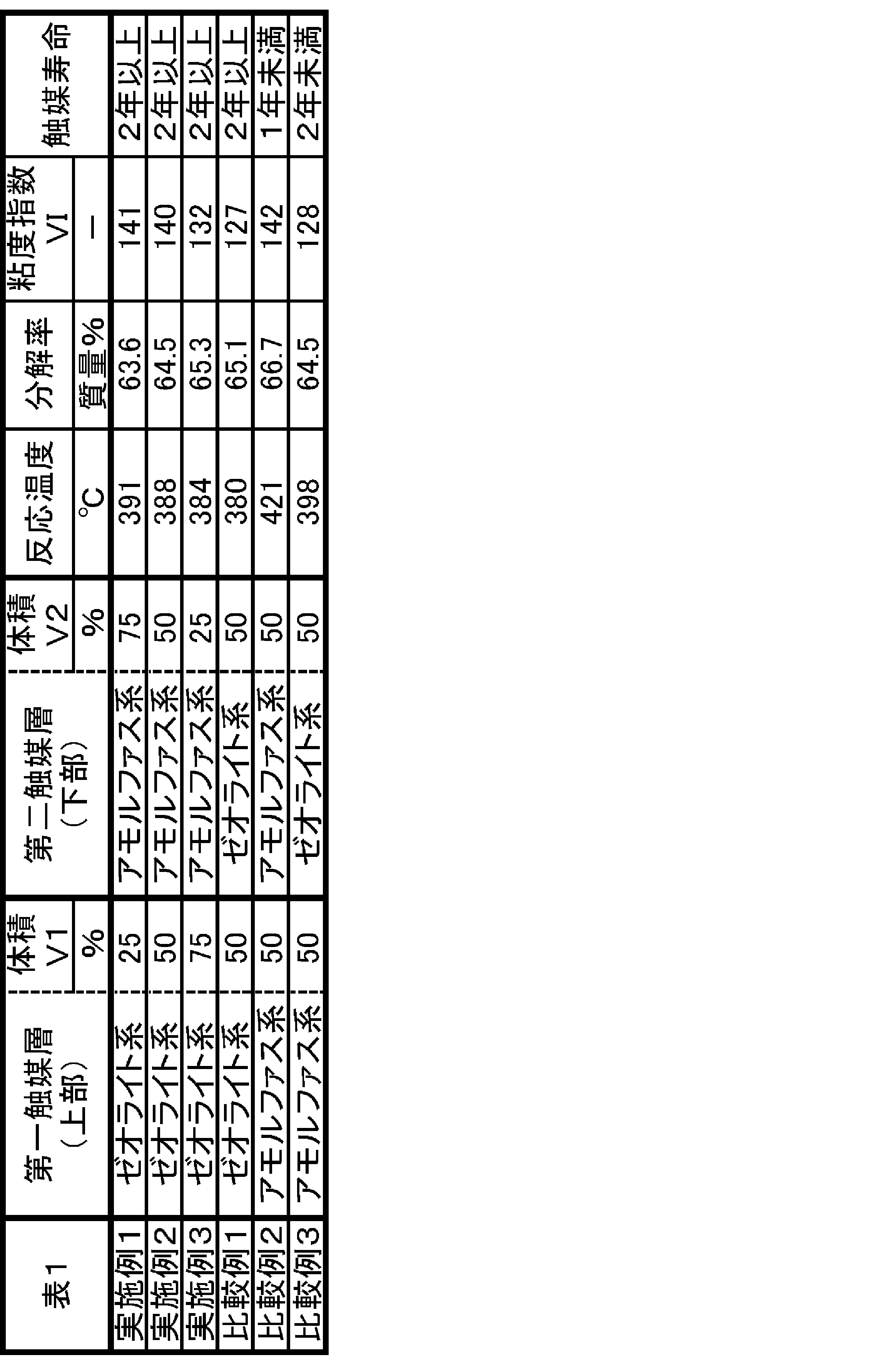
上記表1に記載のVIは、130以上であることが好ましく、140以上であることがより好ましい。上記表1に記載の触媒寿命は、2年以上であることが好ましい。
本発明によれば、水素化分解触媒を用いて、粘度指数が高い潤滑油基油を長時間に渡って製造し続けることが可能となる。
1…第一触媒層(第一水素化分解触媒)、2…第二触媒層(第二水素化分解触媒)、4…原料油、5A…第一生成油、5B…第二生成油(潤滑油基油)。
Claims (4)
- 芳香族炭化水素を含有する原料油を、水素ガスの存在下で第一水素化分解触媒に接触させて、第一生成油を得る第一工程と、
前記第一生成油を、水素ガスの存在下で第二水素化分解触媒に接触させて、第二生成油を得る第二工程と、
を備え、
前記第一水素化分解触媒が、ゼオライトを含有し、
前記第二水素化分解触媒が、非晶質の固体酸を含有する、
潤滑油基油の製造方法。 - 前記第一水素化分解触媒の体積が、V1であり、
前記第二水素化分解触媒の体積が、V2であるとき、
100・V1/(V1+V2)が、5~50である、
請求項1に記載の潤滑油基油の製造方法。 - 前記第一水素化分解触媒を含む第一触媒層と、前記第二水素化分解触媒を含む第二触媒層と、が、一つの固定床型反応器内に固定されており、
前記第一工程では、前記原料油を前記第一触媒層へ流して、前記第一生成油を得て、
前記第二工程では、前記第一生成油を前記第一触媒層から前記第二触媒層へ流して、前記第二生成油を得る、
請求項1又は2に記載の潤滑油基油の製造方法。 - 前記原料油が、減圧軽油である、
請求項1~3のいずれか一項に記載の潤滑油基油の製造方法。
Applications Claiming Priority (2)
| Application Number | Priority Date | Filing Date | Title |
|---|---|---|---|
| JP2015-191327 | 2015-09-29 | ||
| JP2015191327A JP6506667B2 (ja) | 2015-09-29 | 2015-09-29 | 潤滑油基油の製造方法 |
Publications (1)
| Publication Number | Publication Date |
|---|---|
| WO2017056550A1 true WO2017056550A1 (ja) | 2017-04-06 |
Family
ID=58423414
Family Applications (1)
| Application Number | Title | Priority Date | Filing Date |
|---|---|---|---|
| PCT/JP2016/065811 Ceased WO2017056550A1 (ja) | 2015-09-29 | 2016-05-27 | 潤滑油基油の製造方法 |
Country Status (2)
| Country | Link |
|---|---|
| JP (1) | JP6506667B2 (ja) |
| WO (1) | WO2017056550A1 (ja) |
Citations (4)
| Publication number | Priority date | Publication date | Assignee | Title |
|---|---|---|---|---|
| JPH07241472A (ja) * | 1993-09-28 | 1995-09-19 | Intevep Sa | 原料の水素化分解及びその触媒 |
| JP2000515185A (ja) * | 1996-07-15 | 2000-11-14 | シェブロン ユー.エス.エー.インコーポレイテッド | 潤滑油の水素化変換(hydroconversion)用層状触媒 |
| JP2001526706A (ja) * | 1996-10-31 | 2001-12-18 | モービル・オイル・コーポレイション | 触媒の老化を遅延させる高形状選択的脱ロウ方法 |
| JP2004531607A (ja) * | 2001-04-19 | 2004-10-14 | シエル・インターナシヨネイル・リサーチ・マーチヤツピイ・ベー・ウイ | 高飽和物含有量を有するベース油の製造方法 |
-
2015
- 2015-09-29 JP JP2015191327A patent/JP6506667B2/ja active Active
-
2016
- 2016-05-27 WO PCT/JP2016/065811 patent/WO2017056550A1/ja not_active Ceased
Patent Citations (4)
| Publication number | Priority date | Publication date | Assignee | Title |
|---|---|---|---|---|
| JPH07241472A (ja) * | 1993-09-28 | 1995-09-19 | Intevep Sa | 原料の水素化分解及びその触媒 |
| JP2000515185A (ja) * | 1996-07-15 | 2000-11-14 | シェブロン ユー.エス.エー.インコーポレイテッド | 潤滑油の水素化変換(hydroconversion)用層状触媒 |
| JP2001526706A (ja) * | 1996-10-31 | 2001-12-18 | モービル・オイル・コーポレイション | 触媒の老化を遅延させる高形状選択的脱ロウ方法 |
| JP2004531607A (ja) * | 2001-04-19 | 2004-10-14 | シエル・インターナシヨネイル・リサーチ・マーチヤツピイ・ベー・ウイ | 高飽和物含有量を有するベース油の製造方法 |
Also Published As
| Publication number | Publication date |
|---|---|
| JP2017066227A (ja) | 2017-04-06 |
| JP6506667B2 (ja) | 2019-04-24 |
Similar Documents
| Publication | Publication Date | Title |
|---|---|---|
| CA2946285C (en) | Middle distillate hydrocracking catalyst with a base extrudate having a high nanopore volume | |
| CN105916967A (zh) | 润滑基础油生产 | |
| CN105247016B (zh) | 润滑油基础油的制造方法 | |
| CN102844116A (zh) | 氢化异构化催化剂、其制造方法、烃油的脱蜡方法、烃的制造方法以及润滑油基础油的制造方法 | |
| US10894922B2 (en) | Processing vacuum residuum and vacuum gas oil in ebullated bed reactor systems | |
| US20150209772A1 (en) | Process for preparing hydrocracking catalyst | |
| US8367883B2 (en) | Synthetic naphtha manufacturing method | |
| CN107051427A (zh) | 加氢精制催化剂及烃油的制造方法 | |
| EP3200916B1 (en) | Hydroisomerization catalyst manufactured using high nanopore volume alumina supports and hydroisomerization process | |
| US20150306583A1 (en) | Middle distillate hydrocracking catalyst with a base extrudate having a high nanopore volume | |
| CN101040032B (zh) | 重质烃油加氢处理的方法 | |
| US20160089664A1 (en) | Hydroisomerization catalyst with a base extrudate having a high total nanopore volume | |
| CN103459025B (zh) | 加氢裂化催化剂及烃油的制造方法 | |
| CN103459024B (zh) | 加氢处理用催化剂的制造方法 | |
| KR20230100734A (ko) | Ssz-91을 사용하는 높은 나노세공 부피 촉매 및 방법 | |
| US20220154086A1 (en) | Method for producing lubricant base oil | |
| JP6506667B2 (ja) | 潤滑油基油の製造方法 | |
| JP6038708B2 (ja) | 石油製品の製造方法 | |
| CN103339231B (zh) | 烃油的制造方法 | |
| CN103459016A (zh) | 再生加氢精制催化剂及烃油的制造方法 | |
| JP6023537B2 (ja) | 炭化水素油の水素化処理方法及び潤滑油用基油の製造方法 | |
| KR20200081419A (ko) | 수소화전환 반응기에서 열을 분산하기 위한 촉매 담지 방법 | |
| JP2017218538A (ja) | 潤滑油基油の製造方法 | |
| CA3020602C (en) | A method of operating an ebullated bed process to reduce sediment yield | |
| JP2017066226A (ja) | 炭化水素油の製造方法 |
Legal Events
| Date | Code | Title | Description |
|---|---|---|---|
| 121 | Ep: the epo has been informed by wipo that ep was designated in this application |
Ref document number: 16850727 Country of ref document: EP Kind code of ref document: A1 |
|
| NENP | Non-entry into the national phase |
Ref country code: DE |
|
| 122 | Ep: pct application non-entry in european phase |
Ref document number: 16850727 Country of ref document: EP Kind code of ref document: A1 |