WO2017051708A1 - 車載用電源装置及びその制御方法 - Google Patents
車載用電源装置及びその制御方法 Download PDFInfo
- Publication number
- WO2017051708A1 WO2017051708A1 PCT/JP2016/076243 JP2016076243W WO2017051708A1 WO 2017051708 A1 WO2017051708 A1 WO 2017051708A1 JP 2016076243 W JP2016076243 W JP 2016076243W WO 2017051708 A1 WO2017051708 A1 WO 2017051708A1
- Authority
- WO
- WIPO (PCT)
- Prior art keywords
- switch
- power supply
- current
- relay
- battery
- Prior art date
- Legal status (The legal status is an assumption and is not a legal conclusion. Google has not performed a legal analysis and makes no representation as to the accuracy of the status listed.)
- Ceased
Links
Images


Classifications
-
- B—PERFORMING OPERATIONS; TRANSPORTING
- B60—VEHICLES IN GENERAL
- B60R—VEHICLES, VEHICLE FITTINGS, OR VEHICLE PARTS, NOT OTHERWISE PROVIDED FOR
- B60R16/00—Electric or fluid circuits specially adapted for vehicles and not otherwise provided for; Arrangement of elements of electric or fluid circuits specially adapted for vehicles and not otherwise provided for
- B60R16/02—Electric or fluid circuits specially adapted for vehicles and not otherwise provided for; Arrangement of elements of electric or fluid circuits specially adapted for vehicles and not otherwise provided for electric constitutive elements
- B60R16/03—Electric or fluid circuits specially adapted for vehicles and not otherwise provided for; Arrangement of elements of electric or fluid circuits specially adapted for vehicles and not otherwise provided for electric constitutive elements for supply of electrical power to vehicle subsystems or for
- B60R16/033—Electric or fluid circuits specially adapted for vehicles and not otherwise provided for; Arrangement of elements of electric or fluid circuits specially adapted for vehicles and not otherwise provided for electric constitutive elements for supply of electrical power to vehicle subsystems or for characterised by the use of electrical cells or batteries
-
- H—ELECTRICITY
- H02—GENERATION; CONVERSION OR DISTRIBUTION OF ELECTRIC POWER
- H02J—CIRCUIT ARRANGEMENTS OR SYSTEMS FOR SUPPLYING OR DISTRIBUTING ELECTRIC POWER; SYSTEMS FOR STORING ELECTRIC ENERGY
- H02J7/00—Circuit arrangements for charging or depolarising batteries or for supplying loads from batteries
- H02J7/0029—Circuit arrangements for charging or depolarising batteries or for supplying loads from batteries with safety or protection devices or circuits
- H02J7/00304—Overcurrent protection
-
- H—ELECTRICITY
- H02—GENERATION; CONVERSION OR DISTRIBUTION OF ELECTRIC POWER
- H02J—CIRCUIT ARRANGEMENTS OR SYSTEMS FOR SUPPLYING OR DISTRIBUTING ELECTRIC POWER; SYSTEMS FOR STORING ELECTRIC ENERGY
- H02J7/00—Circuit arrangements for charging or depolarising batteries or for supplying loads from batteries
- H02J7/0029—Circuit arrangements for charging or depolarising batteries or for supplying loads from batteries with safety or protection devices or circuits
- H02J7/0031—Circuit arrangements for charging or depolarising batteries or for supplying loads from batteries with safety or protection devices or circuits using battery or load disconnect circuits
-
- H—ELECTRICITY
- H02—GENERATION; CONVERSION OR DISTRIBUTION OF ELECTRIC POWER
- H02J—CIRCUIT ARRANGEMENTS OR SYSTEMS FOR SUPPLYING OR DISTRIBUTING ELECTRIC POWER; SYSTEMS FOR STORING ELECTRIC ENERGY
- H02J7/00—Circuit arrangements for charging or depolarising batteries or for supplying loads from batteries
- H02J7/14—Circuit arrangements for charging or depolarising batteries or for supplying loads from batteries for charging batteries from dynamo-electric generators driven at varying speed, e.g. on vehicle
- H02J7/1423—Circuit arrangements for charging or depolarising batteries or for supplying loads from batteries for charging batteries from dynamo-electric generators driven at varying speed, e.g. on vehicle with multiple batteries
-
- H—ELECTRICITY
- H02—GENERATION; CONVERSION OR DISTRIBUTION OF ELECTRIC POWER
- H02H—EMERGENCY PROTECTIVE CIRCUIT ARRANGEMENTS
- H02H3/00—Emergency protective circuit arrangements for automatic disconnection directly responsive to an undesired change from normal electric working condition with or without subsequent reconnection ; integrated protection
- H02H3/08—Emergency protective circuit arrangements for automatic disconnection directly responsive to an undesired change from normal electric working condition with or without subsequent reconnection ; integrated protection responsive to excess current
- H02H3/087—Emergency protective circuit arrangements for automatic disconnection directly responsive to an undesired change from normal electric working condition with or without subsequent reconnection ; integrated protection responsive to excess current for DC applications
-
- H—ELECTRICITY
- H02—GENERATION; CONVERSION OR DISTRIBUTION OF ELECTRIC POWER
- H02J—CIRCUIT ARRANGEMENTS OR SYSTEMS FOR SUPPLYING OR DISTRIBUTING ELECTRIC POWER; SYSTEMS FOR STORING ELECTRIC ENERGY
- H02J1/00—Circuit arrangements for DC mains or DC distribution networks
- H02J1/10—Parallel operation of DC sources
- H02J1/108—Parallel operation of DC sources using diodes blocking reverse current flow
-
- H—ELECTRICITY
- H02—GENERATION; CONVERSION OR DISTRIBUTION OF ELECTRIC POWER
- H02J—CIRCUIT ARRANGEMENTS OR SYSTEMS FOR SUPPLYING OR DISTRIBUTING ELECTRIC POWER; SYSTEMS FOR STORING ELECTRIC ENERGY
- H02J2310/00—The network for supplying or distributing electric power characterised by its spatial reach or by the load
- H02J2310/40—The network being an on-board power network, i.e. within a vehicle
- H02J2310/46—The network being an on-board power network, i.e. within a vehicle for ICE-powered road vehicles
-
- H—ELECTRICITY
- H02—GENERATION; CONVERSION OR DISTRIBUTION OF ELECTRIC POWER
- H02J—CIRCUIT ARRANGEMENTS OR SYSTEMS FOR SUPPLYING OR DISTRIBUTING ELECTRIC POWER; SYSTEMS FOR STORING ELECTRIC ENERGY
- H02J7/00—Circuit arrangements for charging or depolarising batteries or for supplying loads from batteries
- H02J7/0013—Circuit arrangements for charging or depolarising batteries or for supplying loads from batteries acting upon several batteries simultaneously or sequentially
- H02J7/0025—Sequential battery discharge in systems with a plurality of batteries
Definitions
- the present invention relates to an in-vehicle power supply device.
- idling stop load Indicated as “IS load” in the drawing.
- Examples of the idling stop load include a navigation device and an audio device.
- FIG. 15 is a circuit diagram showing a configuration of a battery system in which the in-vehicle power supply device 200 supplies power not only to the general load 5 but also to the idling stop load 7.
- the in-vehicle power supply device 200 includes a main battery (indicated as “main BAT” in the drawing) 1, a sub battery (indicated as “sub BAT” in the drawing) 2, and relays 201, 202, and 203. Relays 201 and 203 are connected in parallel.
- the load 5 is connected to the main battery 1 without passing through the relays 201, 202, 203.
- the sub battery 1 is charged by the power generation function of the alternator 9.
- the sub battery 2 is connected to the main battery 1 through relays 201, 202, 203.
- the idling stop load 7 is connected to the main battery 1 via the relays 201 and 203 and to the sub battery 2 via the relay 202, respectively.
- the relays 201 and 202 are normally open type and the relay 203 is normally closed type, even if a control device (not shown) that controls the relays 201, 202, and 203 fails, the idling stop load 7 is fed from the main battery 1 through the relay 203.
- a control device not shown
- Patent Document 1 Such a technique is introduced in, for example, Patent Document 1 below.
- a failure for example, a ground fault, occurs on the main battery 1 side of the relay 201.
- the relays 201 and 202 are normally controlled so as to transition from the closed state to the open state in order to interrupt the overcurrent when it is detected. Therefore, when it is assumed as described above, overcurrent starts to flow from the sub battery 2 via the relays 201, 202, and 203, and the relay 202 is opened.
- the relay 202 If the relay 202 is in the open state in this way, the power supply from the sub battery 2 to the idling stop load 7 is stopped. Even if the relay 203 is closed at this time, since a failure has occurred on the main battery 1 side, the idling stop load 7 is not substantially supplied with power.
- an object of the present invention is to provide a technology for supplying power to an external load while avoiding the occurrence of overcurrent even when either a failure on the main battery side or a failure on the sub battery side occurs. .
- Each of the in-vehicle power supply devices includes an in-vehicle main battery and an in-vehicle sub battery, a first switch and a second switch, and a main power supply path and a sub power supply path.
- the second switch is connected to the main battery via the first switch.
- the sub battery is connected to the main battery through the first switch and the second switch.
- the main power supply path bypasses the first switch and the second switch and connects the main battery to a load.
- the auxiliary power supply path connects the auxiliary battery to the load via the second switch.
- the first switch transitions from on to off when an overcurrent flows.
- the second switch transitions from on to off when an overcurrent flows after the first switch transitions from on to off.
- the in-vehicle power supply device supplies power to the outside while avoiding the occurrence of overcurrent even when either a failure on the main battery side or a failure on the sub battery side occurs.
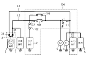
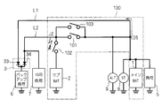
- FIG. 1 is a circuit diagram showing an in-vehicle power supply device 100 according to an embodiment and elements connected thereto.
- the in-vehicle power supply device 100 includes a main battery 1, a sub battery 2, relays 101, 102, and 103, and circuits 401 and 402 (both are expressed as “current / voltage detection” in the drawing).
- Relays 101, 102, and 103 are controlled by an in-vehicle ECU (engine control unit) 403 to open / close.
- the vehicle-mounted ECU 403 causes the relays 101, 102, and 103 to transition between the open state and the closed state when an overvoltage or overcurrent is detected in the circuits 401 and 402.
- the main battery 1 and the sub battery 2 are both for vehicle use, and relays 101 and 102 are connected in series between them.
- Relay 101 is connected to main battery 1 via circuit 401
- relay 102 is connected to main battery 1 via relay 101 and circuit 401.
- Relays 101 and 103 are connected in parallel.
- the relays 101, 102, and 103 can be grasped as a first switch, a second switch, and a third switch in which the closed state / open state correspond to ON / OFF, respectively.
- the main battery 1 is charged from the outside of the in-vehicle power supply device 100. Specifically, the main battery 1 is connected to an on-vehicle alternator 9 and is charged by the power generation function of the alternator 9. The sub battery 2 is charged by at least one of the alternator 9 and the main battery 1.
- the main battery 1 is, for example, a lead storage battery
- the secondary battery 2 is, for example, a lithium ion battery.
- Each of the main battery 1 and the sub battery 2 is a concept including a capacitor.
- an electric double layer capacitor may be employed for the sub battery 2.
- a starter 8 is connected to the main battery 1 together with a general load 5 from the outside of the in-vehicle power supply device 100.
- the load 5 is a load that is not subject to backup of the sub-battery 2, and is, for example, an in-vehicle air conditioner.
- the starter 8 is a motor that starts an engine (not shown). Since the load 5 and the starter 8 are known loads and do not have specific characteristics in the embodiment, detailed description thereof is omitted.
- the backup load 6 is a load for which power supply is desired to be maintained even when the power supply from the main battery 1 is lost, and examples include a shift-by-wire actuator and an electronically controlled braking force distribution system.
- the in-vehicle power supply device 100 further includes a main power supply path L1 and a sub power supply path L2, and supplies power to the backup load 6 through these.
- the main power supply path L1 connects the main battery 1, the load 5, and the backup load 6 in parallel with a fixed potential point (here, ground). That is, both the load 5 and the backup load 6 receive power via the main power supply path L1.
- the main power supply path L1 connects the main battery 1 and the backup load 6 without passing through the relays 101, 102, 103 (that is, bypassing them).
- the sub power feeding path L ⁇ b> 2 is connected to the sub battery 2 via the relay 102 and the circuit 402. Therefore, the backup load 6 can receive power not only from the main battery 1 but also from the sub battery 2.
- the diode group 3 is interposed between the backup load 6 and the main power supply path L1 and the sub power supply path L2.
- the diode group 3 prevents current from flowing between the main battery 1 and the sub battery 2 via the main power supply path L1 and the sub power supply path L2. This is because the wraparound causes deterioration of one or both of the main battery 1 and the sub battery 2.
- both the main battery 1 and the sub battery 2 supply power to the backup load 6 at a potential higher than ground.
- the cathodes of the pair of diodes 33 and 34 constituting the diode group 3 are connected in common and connected to the backup load 6.
- the anode of the diode 33 is connected to the main power supply path L1
- the anode of the diode 34 is connected to the sub power supply path L2.
- the idling stop load 7 is connected to the auxiliary power supply path L2, and is connected to the auxiliary battery 2 via the relay 102 and the circuit 402. Further, it is connected to the main battery 1 via the relays 101 and 103 and the circuit 401.
- the connection relationship between the idling stop load 7 and the relays 101, 102, 103 and the main battery 1 and the sub battery 2 in the present embodiment is the idling shown in FIG.
- the connection relationship between the stop load 7 and the relays 201, 202, 203, the main battery 1 and the sub battery 2 is the same.
- the circuit 401 and the circuit 402 detect the voltage of the main battery 1 (hereinafter referred to as “main voltage”) and the voltage of the sub battery 2 (hereinafter referred to as “sub voltage”), respectively.
- main voltage the voltage of the main battery 1
- sub voltage the voltage of the sub battery 2
- the in-vehicle ECU 403 sets the open / closed state of the relays 101, 102, and 103 as follows.
- the relays 101 and 102 are both closed and the sub-battery 2 is charged by the main battery 1 and / or the alternator 9. If the sub-voltage is high enough to determine that charging to the sub-battery 2 is excessive, the relays 101 and 103 are opened, and charging to the sub-battery 2 is stopped. At this time, if the relay 102 is closed, power is supplied to the backup load 6 from the main power supply path L1 or the sub power supply path L2 depending on the magnitude relationship between the main voltage and the subvoltage.
- the closed state / open state of the relay 102 is selected according to the operation.
- such selection of the closed state / open state in the relay 102 when the secondary battery 2 is not charged in a normal state is not essential. Therefore, a detailed description of such selection is omitted.
- the circuit 401 detects a current (hereinafter referred to as “first current”) flowing in the parallel connection of the relays 101 and 103. If the in-vehicle ECU 403 determines that the first current is an overcurrent, the in-vehicle ECU 403 opens the relays 101 and 103 even when the secondary battery 2 is charged.
- the circuit 402 detects a current flowing through the relay 102 (hereinafter referred to as “second current”). If the in-vehicle ECU 403 determines that the second current is an overcurrent, the in-vehicle ECU 403 opens the relay 102 even when charging the sub battery 2.
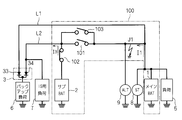
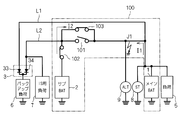
- FIG. 2 is a circuit diagram showing a situation where a ground fault J1 has occurred on the main battery 1 side than the relays 101 and 103 (more precisely, than the circuit 401) when the relays 101, 102, and 103 are in a closed state. is there. Due to the ground fault J1, not only the current I1 flows from the main battery 1 to the ground, but also the current I2 flows from the sub battery 2 to the ground via the relays 101, 102, 103. The same applies when a ground fault occurs in the main power supply path L1.
- the current I2 is a ground fault current and flows not only as the second current but also as the first current. Therefore, the circuits 401 and 402 detect both the first current and the second current as overcurrent.
- both the main battery 1 and the sub battery 2 are short-circuited by the ground fault J1, and power cannot be supplied from either the main power supply path L1 or the sub power supply path L2.
- all of the relays 101, 102, and 103 are in the open state, power supply from the auxiliary power supply path L2 is not continued.
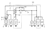
- the relays 101 and 103 transition from the closed state to the open state while the relay 102 remains in the closed state.
- the secondary battery 2 is disconnected from the ground fault J1, and the current I2, which is a ground fault current, does not flow.
- the sub battery 2 supplies the current I3 to the sub power feeding path L2. Since the current I3 is not a ground fault current, the circuit 402 does not determine that the second current is an overcurrent, and therefore the relay 102 remains closed.
- the secondary battery 2 functions as a backup power source for the backup load 6.
- the relays 101 and 103 are once opened, the relays 101 and 103 are not shifted to the closed state even if the overcurrent is not detected in the first current. This is to prevent the current I2 from flowing again as a ground fault current.
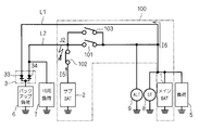
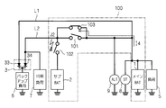
- FIG. 4 shows that when the relays 101, 102, and 103 are in a closed state, a ground fault J2 occurs on the opposite side of the main battery 1 and the sub battery 2 from the relays 101, 102, and 103, that is, on the sub power feeding path L2.
- the relays 101 and 103 transition from the closed state to the open state while the relay 102 is kept in the closed state.
- the diode group 3 due to the function of the diode group 3, as shown in FIG. 5, the main battery 1 is disconnected from the ground fault J2, and the current I6 flows in the main power supply path L1.
- the main battery 1 functions as a backup power source for the backup load 6.
- the main battery 1 functions as a backup power source for the backup load 6.
- the circuit 402 detects the second current as an overcurrent. Then, after the relays 101 and 103 are in the open state, as shown in FIG. 6, the relay 102 transitions from the closed state to the open state. Thus, unlike the case where a failure occurs on the main battery 1 side, the ground fault current flowing from the sub battery 2 on the failure side is also stopped. Thereby, both the main battery 1 and the sub battery 2 are protected from the ground fault J2.
- the relays 101 and 103 are once opened, the relays 101 and 103 are not shifted to the closed state even if the overcurrent is not detected in the first current. This is to prevent the current I4 from flowing again as a ground fault current.
- FIG. 7 is a circuit diagram assuming that the relay 103 is in a closed state when the ground fault J1 occurs. If the relay 103 is in the closed state even when the operation (i) is performed, the current I2 flows as a ground fault current from the sub battery 2 to the ground via the relay 103, and the power supply from the sub power supply path L2 is performed. Not done. Therefore, in the operation (i), the relay 103 should be in an open state as the relay 101 transitions to the open state.
- FIG. 8 is a circuit diagram assuming that the relay 103 is in the closed state when the ground fault J2 occurs. Even if the operations (i) and (ii) are performed, if the relay 103 is in the closed state, the current I4 flows as a ground fault current from the main battery 1 to the ground via the relay 103, and the main power supply path L1 Power is not supplied from. Therefore, in the operations (i) and (ii) above, the relay 103 should be open.
- the relays 101, 102, and 103 As described above, in any of the relays 101, 102, and 103, after the overcurrent is detected and once opened, the relays 101, 102, and 103 are not shifted to the closed state even if the overcurrent is not detected. Therefore, if the relay 103 is opened in the operation (i) by detecting an overcurrent, the relay 103 is still open in the operation (ii). From the above, considering the relay 103 and the like, the relay 103 may operate in the same manner as the relay 101 in the process (i). Such an operation of the relay 103 does not prevent the ground fault current from being interrupted by the relay 101 being in an open state.
- the relays 101 and 103 are normally open type (normally off type when the relay 101 is grasped as a switch), normally closed type (normally on type when the relay 103 is grasped as a switch), respectively. It is different in that it is desirable.
- the relay 102 is desirably a normally open type. The reason why such a desirable type is different between the relays 101, 102, and 103 will be described below.
- a normally closed type is adopted for the relay 103 to ensure power supply from the main battery 1 to the idling stop load 7 via the sub power supply path L2 even when the ignition is off.
- the normally open relays 101 and 102 are in an open state due to malfunction or failure of the in-vehicle ECU 403, the normally closed relay 103 is in the closed state, so that the secondary power is supplied from the main battery 1. Power supply to the backup load 6 through the path L2 is also ensured.
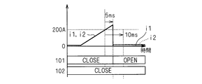
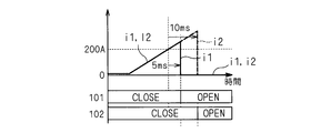
- 9 and 10 are graphs showing the first method.
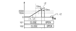
- 11 and 12 are graphs showing the second method.
- the horizontal axis represents time
- the vertical axis represents the current i1 flowing through the relays 101 and 103 and the current i2 flowing through the relay 102 (the currents i1 and i2 are independent of the direction in which they flow). Absolute value).
- “OPEN” indicates that the relays 101 and 102 are in an open state
- CLOSE indicates that the relays 101 and 102 are in a closed state.
- the currents i1 and i2 are both current I2 (see FIG. 2), which is a ground fault current, and increase. Then, after reaching the threshold exemplified as 200A, the currents i1 and i2 continuously exceed the current threshold until the first predetermined time exemplified as 5 ms elapses, and the circuit 401 causes the relay 101 to have an overcurrent. Detects that it has flowed. As a result, the in-vehicle ECU 403 causes the relay 101 to transition from the closed state to the open state (the above operation (i)). As a result, the current i1 becomes 0, and the current i2 flows as the current I3 (see FIG. 3).
- the overcurrent flows through the relay 102. Detect. However, when the ground fault J1 occurs, the value of the current i2 decreases immediately after the first predetermined time elapses as described above. Therefore, the operation (ii) is not executed.
- the currents i1 and i2 are currents I4 and I5 (see FIG. 4), which are ground fault currents, and increase. Then, after reaching the threshold value exemplified as 200A, the current i1 continuously exceeds the current threshold value until the first predetermined time exemplified as 5 ms elapses, and the circuit 401 is said to have passed overcurrent to the relay 101. Detect. As a result, the in-vehicle ECU 403 causes the relay 101 to transition from the closed state to the open state (the above operation (i)). As a result, the current i1 becomes 0, but the current i2 continues to flow as the current I5 (see FIG. 3).
- the circuit 402 detects that an overcurrent has passed through the relay 102 by continuously exceeding the current threshold value until the second predetermined time illustrated as 10 ms elapses after the current i2 exceeds the current threshold value. . Thereby, the vehicle-mounted ECU 403 causes the relay 102 to transition from the closed state to the open state (the above operation (ii)). As a result, the currents i1 and i2 are both 0 (see FIG. 6).
- the first method is summarized as follows: (i-1) The relay 101 changes from the closed state to the open state after the time during which the current exceeding the predetermined value (200 A in the above example) flows through the relay 101 reaches the first time (5 ms in the above example). , (ii-1) The relay 102 transits from the closed state to the open state after the time during which the current exceeding the predetermined value flows through the relay 102 reaches the second time (10 ms in the above example).
- the currents i1 and i2 are both current I2 (see FIG. 2), which is a ground fault current, and increase. Then, after reaching the threshold exemplified as 150A, the current i1 continuously exceeds the current threshold until the first predetermined time exemplified as 10 ms elapses, and the circuit 401 has passed overcurrent to the relay 101. Detect. As a result, the in-vehicle ECU 403 causes the relay 101 to transition from the closed state to the open state (the above operation (i)). As a result, the current i1 becomes 0, and the current i2 flows as the current I3 (see FIG. 3).
- the circuit 402 has a second predetermined time when the current i2 is larger than the current threshold applied to the current i1 (150A in the above example) (current of 200A or more here) is exemplified as 10 ms. If the current flows continuously until it is detected, it is detected that an overcurrent has passed through the relay 102. However, when the ground fault J1 occurs, the value of the current i2 decreases immediately after the first predetermined time elapses as described above. Therefore, the operation (ii) is not executed.
- the currents i1 and i2 are currents I4 and I5 (see FIG. 4), which are ground fault currents, and increase. Then, after reaching the threshold exemplified as 150A, the current i1 continuously exceeds the current threshold until the first predetermined time exemplified as 10 ms elapses, and the circuit 401 has passed overcurrent to the relay 101. Detect. As a result, the in-vehicle ECU 403 causes the relay 101 to transition from the closed state to the open state (the above operation (i)). As a result, the current i1 becomes 0, but the current i2 continues to flow as the current I5 (see FIG. 5).
- a current i2 that is larger than the current threshold applied to the current i1 continuously flows until a second predetermined time illustrated as 10 ms elapses.
- a second predetermined time illustrated as 10 ms elapses it is detected that an overcurrent has flowed through the relay 102.
- the vehicle-mounted ECU 403 causes the relay 102 to transition from the closed state to the open state (the above operation (ii)).
- the currents i1 and i2 are both 0 (see FIG. 6).
- the second approach can be summarized as follows: (i-2) The relay 101 changes from the closed state to the open state after the time during which the current exceeding the predetermined value (150 A in the above example) flows through the relay 101 reaches the first time (10 ms in the above example). , (ii-2) The relay 102 is in an open state from a closed state after a time during which a current larger than the predetermined value (200 A or more in the above example) flows through the relay 102 reaches a second time (10 ms in the above example). Transition to.
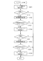
- FIG. 13 is a flowchart showing the first method and the second method as backup control for securing power supply to the backup load 6. Each step shown in the flowchart is executed by, for example, the in-vehicle ECU 403. The operations of the relays 101, 102, and 103 are controlled by the processing of these steps.
- steps S101, S102, S103, and S104 corresponds to the above-described operations (i), (i-1), and (i-2).
- the grouping of steps S201, S202, S203, and S204 corresponds to the above-described operations (ii), (ii-1), and (ii-2).
- step S001 the current flowing through the relays 101, 102, 103 is detected. Specifically, the values of the currents i1 and i2 measured by the circuits 401 and 402 are input to the in-vehicle ECU 403. Such an input is schematically shown by a solid line arrow from the circuits 401 and 402 to the in-vehicle ECU 403 in FIG. Note that step S001 is not stopped by the execution of subsequent steps. Even when steps S102, S201, and S202 described later are executed, step S001 is continuously executed.
- step S101 it is determined whether or not the current flowing through the relay 101 is a large current. Specifically, it is determined whether or not the current i1 is equal to or greater than a current threshold value (this is exemplified as 200A in the first method and 150A in the second method, respectively). If the result of the determination is affirmative (the current i1 is greater than or equal to the current threshold), step S102 is executed. If the result of the determination is negative (the current i1 is less than the current threshold value), the backup control is terminated because no overcurrent is detected.
- a current threshold value this is exemplified as 200A in the first method and 150A in the second method, respectively.
- step S102 the time during which the abnormality continues is measured. Specifically, the time during which the current i1 continuously takes a value equal to or greater than the above-described current threshold is measured.
- step S103 it is determined whether or not the abnormal duration has elapsed. Specifically, whether or not the current i1 continuously flows at a value equal to or greater than the above-described current threshold for a predetermined time (this is exemplified as 5 ms in the first method and 10 ms in the second method). Is judged.
- step S104 is executed, and the determination that an abnormality has occurred is confirmed and the relay is performed.
- 101 is opened. This is schematically shown by a broken line arrow from the in-vehicle ECU 403 to the relay 101 in FIG.
- the determination that an abnormality has occurred is not confirmed and the backup control ends. .
- step S201 it is determined whether or not the current flowing through the relay 102 is a large current. Specifically, it is determined whether or not the current i2 is equal to or greater than a current threshold (this is exemplified as 200A in the first method and the second method). If the result of the determination is affirmative (the current i2 is greater than or equal to the current threshold value), step S202 is executed. If the result of the determination is negative (the current i2 is less than the current threshold value), the backup control ends as no overcurrent is detected.
- a current threshold this is exemplified as 200A in the first method and the second method.
- step S202 the time during which the abnormality continues is measured. Specifically, the time during which the current i2 continuously takes a value equal to or greater than the above-described current threshold is measured.
- step S203 it is determined whether or not the abnormal duration has elapsed. Specifically, it is determined whether or not the current i2 continuously flows at a value equal to or larger than the above-described current threshold for a predetermined time (this is exemplified as 10 ms in the first method and the second method).
- step S204 is executed, and the determination that an abnormality has occurred is confirmed and the relay is performed.
- 102 is opened. This is schematically shown by a broken line arrow from the in-vehicle ECU 403 to the relay 102 in FIG.
- the determination that an abnormality has occurred is not confirmed and the backup control ends. .
- the operation of the relay 103 can be included in the operation (i) as described above.
- the relay 102 may be opened when there is an abnormality in the current i2.
- FIG. 14 is a flowchart showing a part of such a modification.
- FIG. 14 shows an extracted portion from step S101 to step S201 in the flowchart shown in FIG.
- the flowchart shown in FIG. 14 is different from the flowchart shown in FIG. 13 in that step S105 is inserted between step S104 and step S201, and the determination result in step S101 is negative and in step S103. In any case where the determination result is negative, the difference is that step S201 is executed.
- step S105 the relay 103 is brought into an open state in step S104 (this is schematically shown by a broken line arrow from the in-vehicle ECU 403 to the relay 103 in FIG. 1). This is because, as described above, the relay 103 should be open in the operation (i).
- both the case where the determination result in step S101 is negative and the case where the determination result in step S103 is negative are cases where it is not determined that an overcurrent has flowed in the current i1.
- the relay 102 can be opened when the current i2 is abnormal.
- the in-vehicle ECU 403 includes, for example, a microcomputer and a storage device.
- the microcomputer executes each processing step (in other words, a procedure) described in the program.
- the storage device can be composed of one or more of various storage devices such as ROM (Read Only Memory), RAM (Random Access Memory), and rewritable nonvolatile memory (EPROM (Erasable Programmable ROM), etc.).
- the storage device stores various information, data, and the like, stores a program executed by the microcomputer, and provides a work area for executing the program. It can be understood that the microcomputer functions as various means corresponding to each processing step described in the program, or can realize that various functions corresponding to each processing step are realized. Further, the in-vehicle ECU 403 is not limited to this, and various procedures executed by the in-vehicle ECU 403 or various means or various functions implemented may be realized by hardware.
Landscapes
- Engineering & Computer Science (AREA)
- Power Engineering (AREA)
- Mechanical Engineering (AREA)
- Emergency Protection Circuit Devices (AREA)
- Charge And Discharge Circuits For Batteries Or The Like (AREA)
- Control Of Charge By Means Of Generators (AREA)
Priority Applications (2)
| Application Number | Priority Date | Filing Date | Title |
|---|---|---|---|
| CN201680054407.XA CN108028542B (zh) | 2015-09-25 | 2016-09-07 | 车载用电源装置及其控制方法 |
| US15/762,352 US10960835B2 (en) | 2015-09-25 | 2016-09-07 | In-vehicle power supply apparatus and control method for the same |
Applications Claiming Priority (2)
| Application Number | Priority Date | Filing Date | Title |
|---|---|---|---|
| JP2015-187742 | 2015-09-25 | ||
| JP2015187742A JP6398931B2 (ja) | 2015-09-25 | 2015-09-25 | 車載用電源装置及びその制御方法 |
Publications (1)
| Publication Number | Publication Date |
|---|---|
| WO2017051708A1 true WO2017051708A1 (ja) | 2017-03-30 |
Family
ID=58386580
Family Applications (1)
| Application Number | Title | Priority Date | Filing Date |
|---|---|---|---|
| PCT/JP2016/076243 Ceased WO2017051708A1 (ja) | 2015-09-25 | 2016-09-07 | 車載用電源装置及びその制御方法 |
Country Status (4)
| Country | Link |
|---|---|
| US (1) | US10960835B2 (enExample) |
| JP (1) | JP6398931B2 (enExample) |
| CN (1) | CN108028542B (enExample) |
| WO (1) | WO2017051708A1 (enExample) |
Cited By (1)
| Publication number | Priority date | Publication date | Assignee | Title |
|---|---|---|---|---|
| WO2018190338A1 (ja) * | 2017-04-10 | 2018-10-18 | 株式会社デンソー | 電力制御装置および電力制御方法 |
Families Citing this family (9)
| Publication number | Priority date | Publication date | Assignee | Title |
|---|---|---|---|---|
| JP6540565B2 (ja) * | 2016-03-16 | 2019-07-10 | 株式会社オートネットワーク技術研究所 | 車両用電源供給システム、車両用駆動システム |
| JP6750288B2 (ja) * | 2016-04-15 | 2020-09-02 | 株式会社オートネットワーク技術研究所 | リレー装置 |
| JP6915430B2 (ja) * | 2017-07-28 | 2021-08-04 | トヨタ自動車株式会社 | 電源システム |
| EP3921916A4 (en) | 2019-02-05 | 2022-11-30 | Redarc Technologies Pty Ltd | DUAL BATTERY SYSTEM |
| US11489356B2 (en) * | 2019-07-02 | 2022-11-01 | Abb Schweiz Ag | MVDC link-powered battery chargers and operation thereof |
| JP7651900B2 (ja) * | 2021-03-25 | 2025-03-27 | 株式会社オートネットワーク技術研究所 | 異常検出装置、及び異常検出方法 |
| KR20220152826A (ko) * | 2021-05-10 | 2022-11-17 | 현대자동차주식회사 | 차량 전원 시스템 및 그 동작 방법 |
| JP2024141962A (ja) | 2023-03-29 | 2024-10-10 | 株式会社デンソーテン | 電源制御装置および電源制御方法 |
| JP2024143704A (ja) | 2023-03-30 | 2024-10-11 | 株式会社デンソーテン | 制御装置および制御方法 |
Citations (2)
| Publication number | Priority date | Publication date | Assignee | Title |
|---|---|---|---|---|
| JP2012130108A (ja) * | 2010-12-13 | 2012-07-05 | Denso Corp | 電源装置 |
| JP2015076959A (ja) * | 2013-10-08 | 2015-04-20 | 株式会社オートネットワーク技術研究所 | 電源システム |
Family Cites Families (16)
| Publication number | Priority date | Publication date | Assignee | Title |
|---|---|---|---|---|
| JP4728303B2 (ja) * | 2007-08-31 | 2011-07-20 | パナソニック株式会社 | 充電回路、及びこれを備えた電池パック、充電システム |
| JP4687704B2 (ja) * | 2007-11-20 | 2011-05-25 | 株式会社デンソー | 車両用電源装置 |
| US20100109437A1 (en) * | 2008-11-05 | 2010-05-06 | Fattic Gerald T | Battery pack disconnection method for a hybrid vehicle |
| DE102009018612A1 (de) * | 2009-04-23 | 2010-10-28 | Ellenberger & Poensgen Gmbh | Auslöseelement für ein Kraftfahrzeugbordnetz |
| JP5318004B2 (ja) * | 2010-03-01 | 2013-10-16 | 三菱電機株式会社 | 車両用電源システム |
| EP2390982B1 (en) * | 2010-05-25 | 2012-08-29 | Fiat Group Automobiles S.p.A. | Automotive electrical system operation management during coasting and/or with engine off |
| JP5793667B2 (ja) * | 2010-09-29 | 2015-10-14 | パナソニックIpマネジメント株式会社 | 車両用電源装置 |
| CN101976867B (zh) * | 2010-10-21 | 2013-08-28 | 中山大学 | 一种纯电动车用动力电池管理系统及其实现方法 |
| JP2013035238A (ja) * | 2011-08-10 | 2013-02-21 | Riso Kagaku Corp | 孔版印刷装置 |
| JP2013055837A (ja) * | 2011-09-06 | 2013-03-21 | Toyota Industries Corp | 電圧バランス補正回路 |
| JP5825107B2 (ja) * | 2012-01-11 | 2015-12-02 | スズキ株式会社 | 車両用電源装置 |
| KR101397023B1 (ko) * | 2012-03-23 | 2014-05-20 | 삼성에스디아이 주식회사 | 배터리 팩 및 배터리 팩의 제어 방법 |
| CN102691607B (zh) * | 2012-06-08 | 2014-12-03 | 汤如法 | 一种车辆发动机的辅助启动装置 |
| JP5983171B2 (ja) * | 2012-08-10 | 2016-08-31 | 株式会社Gsユアサ | スイッチ故障診断装置、蓄電装置 |
| JP6092638B2 (ja) * | 2013-01-23 | 2017-03-08 | 矢崎総業株式会社 | 車両用電源制御装置 |
| EP2983270A4 (en) * | 2013-04-03 | 2016-07-27 | Autonetworks Technologies Ltd | CONTROL DEVICE, POWER SUPPLY CONTROL DEVICE, CHARGING CONTROL METHOD, CHARGING CONTROL DEVICE AND POWER SUPPLY DEVICE FOR A VEHICLE |
-
2015
- 2015-09-25 JP JP2015187742A patent/JP6398931B2/ja not_active Expired - Fee Related
-
2016
- 2016-09-07 WO PCT/JP2016/076243 patent/WO2017051708A1/ja not_active Ceased
- 2016-09-07 CN CN201680054407.XA patent/CN108028542B/zh not_active Expired - Fee Related
- 2016-09-07 US US15/762,352 patent/US10960835B2/en not_active Expired - Fee Related
Patent Citations (2)
| Publication number | Priority date | Publication date | Assignee | Title |
|---|---|---|---|---|
| JP2012130108A (ja) * | 2010-12-13 | 2012-07-05 | Denso Corp | 電源装置 |
| JP2015076959A (ja) * | 2013-10-08 | 2015-04-20 | 株式会社オートネットワーク技術研究所 | 電源システム |
Cited By (1)
| Publication number | Priority date | Publication date | Assignee | Title |
|---|---|---|---|---|
| WO2018190338A1 (ja) * | 2017-04-10 | 2018-10-18 | 株式会社デンソー | 電力制御装置および電力制御方法 |
Also Published As
| Publication number | Publication date |
|---|---|
| CN108028542A (zh) | 2018-05-11 |
| US20180272968A1 (en) | 2018-09-27 |
| JP2017063551A (ja) | 2017-03-30 |
| US10960835B2 (en) | 2021-03-30 |
| CN108028542B (zh) | 2021-07-13 |
| JP6398931B2 (ja) | 2018-10-03 |
Similar Documents
| Publication | Publication Date | Title |
|---|---|---|
| JP6398931B2 (ja) | 車載用電源装置及びその制御方法 | |
| WO2017051812A1 (ja) | 車載用電源装置及びその制御方法 | |
| US10992165B2 (en) | Redundant power supply system | |
| JP6610456B2 (ja) | バックアップ電源装置およびバックアップシステム | |
| JP6451708B2 (ja) | 車載用のバックアップ装置 | |
| US20150340884A1 (en) | Electric power supply control device and electric power supply control method | |
| US20200195016A1 (en) | Precharge controller | |
| JP6690396B2 (ja) | リレー装置 | |
| JP6627732B2 (ja) | 電源回路装置 | |
| CN107709080A (zh) | 电池管理装置以及电源系统 | |
| JP5994652B2 (ja) | 車両用電源制御装置 | |
| WO2018116741A1 (ja) | 電源システム | |
| JP5167915B2 (ja) | 電動パワーステアリング装置の補助電源システム | |
| US12187208B2 (en) | Power supply control device, control method, and storage medium | |
| JP2022144607A (ja) | 車載電源装置および車載電源制御方法 | |
| US11066027B2 (en) | In-vehicle power supply apparatus configured to charge a plurality of batteries | |
| US20180086220A1 (en) | System and method for charging a vehicle battery | |
| US11299115B2 (en) | Power storage unit control device | |
| JP6107561B2 (ja) | 車両用電源装置 | |
| JP2006304408A (ja) | 電源装置および電源装置の制御方法 | |
| JP2022111637A (ja) | 冗長電源システムおよび冗長電源制御方法 | |
| JP7565803B2 (ja) | 車載電源装置および車載電源制御方法 | |
| WO2020189571A1 (ja) | 電源装置 | |
| JP7643929B2 (ja) | 車両制御装置 | |
| JP7679222B2 (ja) | 電源装置および自動運転システム |
Legal Events
| Date | Code | Title | Description |
|---|---|---|---|
| 121 | Ep: the epo has been informed by wipo that ep was designated in this application |
Ref document number: 16848496 Country of ref document: EP Kind code of ref document: A1 |
|
| WWE | Wipo information: entry into national phase |
Ref document number: 15762352 Country of ref document: US |
|
| NENP | Non-entry into the national phase |
Ref country code: DE |
|
| 122 | Ep: pct application non-entry in european phase |
Ref document number: 16848496 Country of ref document: EP Kind code of ref document: A1 |