WO2017051695A1 - Article absorbant - Google Patents
Article absorbant Download PDFInfo
- Publication number
- WO2017051695A1 WO2017051695A1 PCT/JP2016/075998 JP2016075998W WO2017051695A1 WO 2017051695 A1 WO2017051695 A1 WO 2017051695A1 JP 2016075998 W JP2016075998 W JP 2016075998W WO 2017051695 A1 WO2017051695 A1 WO 2017051695A1
- Authority
- WO
- WIPO (PCT)
- Prior art keywords
- top sheet
- convex portions
- convex
- width
- sheet
- Prior art date
Links
Images


Classifications
-
- A—HUMAN NECESSITIES
- A61—MEDICAL OR VETERINARY SCIENCE; HYGIENE
- A61F—FILTERS IMPLANTABLE INTO BLOOD VESSELS; PROSTHESES; DEVICES PROVIDING PATENCY TO, OR PREVENTING COLLAPSING OF, TUBULAR STRUCTURES OF THE BODY, e.g. STENTS; ORTHOPAEDIC, NURSING OR CONTRACEPTIVE DEVICES; FOMENTATION; TREATMENT OR PROTECTION OF EYES OR EARS; BANDAGES, DRESSINGS OR ABSORBENT PADS; FIRST-AID KITS
- A61F13/00—Bandages or dressings; Absorbent pads
- A61F13/15—Absorbent pads, e.g. sanitary towels, swabs or tampons for external or internal application to the body; Supporting or fastening means therefor; Tampon applicators
- A61F13/51—Absorbent pads, e.g. sanitary towels, swabs or tampons for external or internal application to the body; Supporting or fastening means therefor; Tampon applicators characterised by the outer layers
- A61F13/511—Topsheet, i.e. the permeable cover or layer facing the skin
- A61F13/51104—Topsheet, i.e. the permeable cover or layer facing the skin the top sheet having a three-dimensional cross-section, e.g. corrugations, embossments, recesses or projections
- A61F13/51108—Topsheet, i.e. the permeable cover or layer facing the skin the top sheet having a three-dimensional cross-section, e.g. corrugations, embossments, recesses or projections the top sheet having corrugations or embossments having one axis relatively longer than the other axis, e.g. forming channels or grooves in a longitudinal direction
-
- A—HUMAN NECESSITIES
- A61—MEDICAL OR VETERINARY SCIENCE; HYGIENE
- A61F—FILTERS IMPLANTABLE INTO BLOOD VESSELS; PROSTHESES; DEVICES PROVIDING PATENCY TO, OR PREVENTING COLLAPSING OF, TUBULAR STRUCTURES OF THE BODY, e.g. STENTS; ORTHOPAEDIC, NURSING OR CONTRACEPTIVE DEVICES; FOMENTATION; TREATMENT OR PROTECTION OF EYES OR EARS; BANDAGES, DRESSINGS OR ABSORBENT PADS; FIRST-AID KITS
- A61F13/00—Bandages or dressings; Absorbent pads
- A61F13/15—Absorbent pads, e.g. sanitary towels, swabs or tampons for external or internal application to the body; Supporting or fastening means therefor; Tampon applicators
- A61F13/53—Absorbent pads, e.g. sanitary towels, swabs or tampons for external or internal application to the body; Supporting or fastening means therefor; Tampon applicators characterised by the absorbing medium
- A61F13/534—Absorbent pads, e.g. sanitary towels, swabs or tampons for external or internal application to the body; Supporting or fastening means therefor; Tampon applicators characterised by the absorbing medium having an inhomogeneous composition through the thickness of the pad
- A61F13/537—Absorbent pads, e.g. sanitary towels, swabs or tampons for external or internal application to the body; Supporting or fastening means therefor; Tampon applicators characterised by the absorbing medium having an inhomogeneous composition through the thickness of the pad characterised by a layer facilitating or inhibiting flow in one direction or plane, e.g. a wicking layer
- A61F13/5376—Absorbent pads, e.g. sanitary towels, swabs or tampons for external or internal application to the body; Supporting or fastening means therefor; Tampon applicators characterised by the absorbing medium having an inhomogeneous composition through the thickness of the pad characterised by a layer facilitating or inhibiting flow in one direction or plane, e.g. a wicking layer characterised by the performance of the layer, e.g. acquisition rate, distribution time, transfer time
-
- A—HUMAN NECESSITIES
- A61—MEDICAL OR VETERINARY SCIENCE; HYGIENE
- A61F—FILTERS IMPLANTABLE INTO BLOOD VESSELS; PROSTHESES; DEVICES PROVIDING PATENCY TO, OR PREVENTING COLLAPSING OF, TUBULAR STRUCTURES OF THE BODY, e.g. STENTS; ORTHOPAEDIC, NURSING OR CONTRACEPTIVE DEVICES; FOMENTATION; TREATMENT OR PROTECTION OF EYES OR EARS; BANDAGES, DRESSINGS OR ABSORBENT PADS; FIRST-AID KITS
- A61F13/00—Bandages or dressings; Absorbent pads
- A61F13/15—Absorbent pads, e.g. sanitary towels, swabs or tampons for external or internal application to the body; Supporting or fastening means therefor; Tampon applicators
- A61F13/51—Absorbent pads, e.g. sanitary towels, swabs or tampons for external or internal application to the body; Supporting or fastening means therefor; Tampon applicators characterised by the outer layers
- A61F13/511—Topsheet, i.e. the permeable cover or layer facing the skin
- A61F13/51104—Topsheet, i.e. the permeable cover or layer facing the skin the top sheet having a three-dimensional cross-section, e.g. corrugations, embossments, recesses or projections
-
- A—HUMAN NECESSITIES
- A61—MEDICAL OR VETERINARY SCIENCE; HYGIENE
- A61F—FILTERS IMPLANTABLE INTO BLOOD VESSELS; PROSTHESES; DEVICES PROVIDING PATENCY TO, OR PREVENTING COLLAPSING OF, TUBULAR STRUCTURES OF THE BODY, e.g. STENTS; ORTHOPAEDIC, NURSING OR CONTRACEPTIVE DEVICES; FOMENTATION; TREATMENT OR PROTECTION OF EYES OR EARS; BANDAGES, DRESSINGS OR ABSORBENT PADS; FIRST-AID KITS
- A61F13/00—Bandages or dressings; Absorbent pads
- A61F13/15—Absorbent pads, e.g. sanitary towels, swabs or tampons for external or internal application to the body; Supporting or fastening means therefor; Tampon applicators
- A61F13/51—Absorbent pads, e.g. sanitary towels, swabs or tampons for external or internal application to the body; Supporting or fastening means therefor; Tampon applicators characterised by the outer layers
- A61F13/511—Topsheet, i.e. the permeable cover or layer facing the skin
- A61F13/513—Topsheet, i.e. the permeable cover or layer facing the skin characterised by its function or properties, e.g. stretchability, breathability, rewet, visual effect; having areas of different permeability
-
- A—HUMAN NECESSITIES
- A61—MEDICAL OR VETERINARY SCIENCE; HYGIENE
- A61F—FILTERS IMPLANTABLE INTO BLOOD VESSELS; PROSTHESES; DEVICES PROVIDING PATENCY TO, OR PREVENTING COLLAPSING OF, TUBULAR STRUCTURES OF THE BODY, e.g. STENTS; ORTHOPAEDIC, NURSING OR CONTRACEPTIVE DEVICES; FOMENTATION; TREATMENT OR PROTECTION OF EYES OR EARS; BANDAGES, DRESSINGS OR ABSORBENT PADS; FIRST-AID KITS
- A61F13/00—Bandages or dressings; Absorbent pads
- A61F13/15—Absorbent pads, e.g. sanitary towels, swabs or tampons for external or internal application to the body; Supporting or fastening means therefor; Tampon applicators
- A61F13/53—Absorbent pads, e.g. sanitary towels, swabs or tampons for external or internal application to the body; Supporting or fastening means therefor; Tampon applicators characterised by the absorbing medium
- A61F13/531—Absorbent pads, e.g. sanitary towels, swabs or tampons for external or internal application to the body; Supporting or fastening means therefor; Tampon applicators characterised by the absorbing medium having a homogeneous composition through the thickness of the pad
- A61F13/532—Absorbent pads, e.g. sanitary towels, swabs or tampons for external or internal application to the body; Supporting or fastening means therefor; Tampon applicators characterised by the absorbing medium having a homogeneous composition through the thickness of the pad inhomogeneous in the plane of the pad
-
- A—HUMAN NECESSITIES
- A61—MEDICAL OR VETERINARY SCIENCE; HYGIENE
- A61F—FILTERS IMPLANTABLE INTO BLOOD VESSELS; PROSTHESES; DEVICES PROVIDING PATENCY TO, OR PREVENTING COLLAPSING OF, TUBULAR STRUCTURES OF THE BODY, e.g. STENTS; ORTHOPAEDIC, NURSING OR CONTRACEPTIVE DEVICES; FOMENTATION; TREATMENT OR PROTECTION OF EYES OR EARS; BANDAGES, DRESSINGS OR ABSORBENT PADS; FIRST-AID KITS
- A61F13/00—Bandages or dressings; Absorbent pads
- A61F13/15—Absorbent pads, e.g. sanitary towels, swabs or tampons for external or internal application to the body; Supporting or fastening means therefor; Tampon applicators
- A61F13/15577—Apparatus or processes for manufacturing
- A61F13/15804—Plant, e.g. involving several steps
-
- A—HUMAN NECESSITIES
- A61—MEDICAL OR VETERINARY SCIENCE; HYGIENE
- A61F—FILTERS IMPLANTABLE INTO BLOOD VESSELS; PROSTHESES; DEVICES PROVIDING PATENCY TO, OR PREVENTING COLLAPSING OF, TUBULAR STRUCTURES OF THE BODY, e.g. STENTS; ORTHOPAEDIC, NURSING OR CONTRACEPTIVE DEVICES; FOMENTATION; TREATMENT OR PROTECTION OF EYES OR EARS; BANDAGES, DRESSINGS OR ABSORBENT PADS; FIRST-AID KITS
- A61F13/00—Bandages or dressings; Absorbent pads
- A61F13/15—Absorbent pads, e.g. sanitary towels, swabs or tampons for external or internal application to the body; Supporting or fastening means therefor; Tampon applicators
- A61F13/51—Absorbent pads, e.g. sanitary towels, swabs or tampons for external or internal application to the body; Supporting or fastening means therefor; Tampon applicators characterised by the outer layers
- A61F2013/51078—Absorbent pads, e.g. sanitary towels, swabs or tampons for external or internal application to the body; Supporting or fastening means therefor; Tampon applicators characterised by the outer layers being embossed
-
- A—HUMAN NECESSITIES
- A61—MEDICAL OR VETERINARY SCIENCE; HYGIENE
- A61F—FILTERS IMPLANTABLE INTO BLOOD VESSELS; PROSTHESES; DEVICES PROVIDING PATENCY TO, OR PREVENTING COLLAPSING OF, TUBULAR STRUCTURES OF THE BODY, e.g. STENTS; ORTHOPAEDIC, NURSING OR CONTRACEPTIVE DEVICES; FOMENTATION; TREATMENT OR PROTECTION OF EYES OR EARS; BANDAGES, DRESSINGS OR ABSORBENT PADS; FIRST-AID KITS
- A61F13/00—Bandages or dressings; Absorbent pads
- A61F13/15—Absorbent pads, e.g. sanitary towels, swabs or tampons for external or internal application to the body; Supporting or fastening means therefor; Tampon applicators
- A61F13/51—Absorbent pads, e.g. sanitary towels, swabs or tampons for external or internal application to the body; Supporting or fastening means therefor; Tampon applicators characterised by the outer layers
- A61F13/511—Topsheet, i.e. the permeable cover or layer facing the skin
- A61F13/513—Topsheet, i.e. the permeable cover or layer facing the skin characterised by its function or properties, e.g. stretchability, breathability, rewet, visual effect; having areas of different permeability
- A61F2013/51338—Topsheet, i.e. the permeable cover or layer facing the skin characterised by its function or properties, e.g. stretchability, breathability, rewet, visual effect; having areas of different permeability having improved touch or feeling, e.g. smooth film
-
- A—HUMAN NECESSITIES
- A61—MEDICAL OR VETERINARY SCIENCE; HYGIENE
- A61F—FILTERS IMPLANTABLE INTO BLOOD VESSELS; PROSTHESES; DEVICES PROVIDING PATENCY TO, OR PREVENTING COLLAPSING OF, TUBULAR STRUCTURES OF THE BODY, e.g. STENTS; ORTHOPAEDIC, NURSING OR CONTRACEPTIVE DEVICES; FOMENTATION; TREATMENT OR PROTECTION OF EYES OR EARS; BANDAGES, DRESSINGS OR ABSORBENT PADS; FIRST-AID KITS
- A61F13/00—Bandages or dressings; Absorbent pads
- A61F13/15—Absorbent pads, e.g. sanitary towels, swabs or tampons for external or internal application to the body; Supporting or fastening means therefor; Tampon applicators
- A61F13/53—Absorbent pads, e.g. sanitary towels, swabs or tampons for external or internal application to the body; Supporting or fastening means therefor; Tampon applicators characterised by the absorbing medium
- A61F13/534—Absorbent pads, e.g. sanitary towels, swabs or tampons for external or internal application to the body; Supporting or fastening means therefor; Tampon applicators characterised by the absorbing medium having an inhomogeneous composition through the thickness of the pad
- A61F13/537—Absorbent pads, e.g. sanitary towels, swabs or tampons for external or internal application to the body; Supporting or fastening means therefor; Tampon applicators characterised by the absorbing medium having an inhomogeneous composition through the thickness of the pad characterised by a layer facilitating or inhibiting flow in one direction or plane, e.g. a wicking layer
- A61F2013/53765—Absorbent pads, e.g. sanitary towels, swabs or tampons for external or internal application to the body; Supporting or fastening means therefor; Tampon applicators characterised by the absorbing medium having an inhomogeneous composition through the thickness of the pad characterised by a layer facilitating or inhibiting flow in one direction or plane, e.g. a wicking layer characterized by its geometry
- A61F2013/53778—Absorbent pads, e.g. sanitary towels, swabs or tampons for external or internal application to the body; Supporting or fastening means therefor; Tampon applicators characterised by the absorbing medium having an inhomogeneous composition through the thickness of the pad characterised by a layer facilitating or inhibiting flow in one direction or plane, e.g. a wicking layer characterized by its geometry with grooves
Definitions
- the present invention relates to absorbent articles such as disposable diapers and sanitary napkins.
- the absorbent article is worn with the crotch portion sandwiched between both legs of the wearer and contracted to some extent in the width direction.
- the absorber in the front-rear direction range including the crotch part is provided with a slit or a concave groove having a predetermined width extending in the front-rear direction (for example, see Patent Documents 1 and 2).
- the absorbent article in a worn state is in a state where the crotch portion is sandwiched between both legs of the wearer and contracted to some extent in the width direction as described above, so that the slits and grooves are crushed in the width direction. It was maintained, and the improvement of diffusivity was sometimes inhibited.
- This problem can also be solved by ensuring wide slits and grooves, but in that case, the amount of absorption decreases and the slit formation region in the absorber is excessively deformed by the movement of both legs.
- twists and cracks are easily generated, and the shape of the slit is liable to collapse.
- the main problem of the present invention is to suppress crushing of the slits of the absorber.
- a disposable diaper having a crotch part and a front part and a rear part extending respectively to the front side and the rear side of the crotch part
- An absorbent body provided in a front-rear direction range including the crotch portion;
- a top sheet covering the front side of the absorber, Including A groove having a predetermined width or a slit having a predetermined width extending from the front surface to the back side is extended in the front-rear direction at least in the absorber in the crotch portion,
- the top sheet has a depressed portion that falls into the concave groove or slit of the absorber, and has a convex portion at least at a part of the depressed portion.
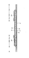
- FIG. 2 is a YY sectional view of FIG. 1.
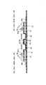
- FIG. 2 is a sectional view taken along line XX in FIG. It is a figure which shows the pad type disposable diaper in this embodiment. It is a figure which shows the pad type disposable diaper in this embodiment. It is a top view which shows only the principal part of another example.
- FIG. 7 is a cross-sectional view of another example corresponding to the XX cross section of the form shown in FIG. 1. It is a top view which shows the other example of the absorber in this embodiment. It is a top view of a top sheet and an intermediate sheet.
- FIG.12 (b) It is explanatory drawing of the assembly equipment example of a top sheet and an intermediate sheet. It is the photograph from the upper direction of the assembly of a top sheet and an intermediate sheet. It is the photograph which image
- groin in the terminology of the present invention means a part that corresponds to the crotch of the body at the time of use, and depending on the product, from the center in the front-rear direction of the article as shown in the figure to the predetermined part on the front side.
- front part (abdominal part) means a part on the front side of the crotch part
- rear part (back side part) means a part on the rear side of the crotch part.
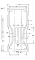
- a pad-type disposable diaper will be described as an example of an absorbent article.
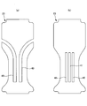
- the pad-type disposable diaper 200 includes a crotch portion C2, and a front portion F2 and a rear portion B2 extending on both front and rear sides thereof.
- the dimensions of each part can be determined as appropriate.
- the total length (length in the front-rear direction) L is about 350 to 700 mm
- the total width W1 is about 130 to 400 mm (however, wider than the width of the absorbent surface of the diaper). it can.
- the crotch portion C2 has a length in the front-rear direction of about 10 to 150 mm
- the front portion F2 has a length in the front-rear direction of about 50 to 350 mm
- the rear portion B2 has a length in the front-rear direction of about 50 to 350 mm.
- the width C3 of the crotch portion C2 can be set to 150 cm or more, particularly about 200 to 260 cm for adults.
- the pad-type disposable diaper 200 has an absorbent body 23 interposed between an inner surface of a liquid-impermeable sheet 21 having an outer sheet 27 laminated on the outer surface and a liquid-permeable top sheet 22. It has a basic structure.
- the liquid-impermeable sheet 21 is provided on the back side of the absorber 23 so as to protrude slightly from the peripheral edge of the absorber 23.
- a sheet having moisture permeability can be used in addition to a polyethylene film or the like without impairing the water barrier from the viewpoint of preventing stuffiness.
- This water-impervious / breathable sheet is a microporous sheet obtained by, for example, melt-kneading an inorganic filler in an olefin resin such as polyethylene or polypropylene to form a sheet, and then stretching in a uniaxial or biaxial direction. Can be used.
- the outer surface of the liquid-impermeable sheet 21 is covered with an exterior sheet 27 made of a nonwoven fabric, and the exterior sheet 27 protrudes outside the periphery of the back sheet 21 with a predetermined protrusion width.
- Various nonwoven fabrics can be used as the exterior sheet 27.
- synthetic fibers such as polyethylene or polypropylene, synthetic fibers such as polyester and amide, recycled fibers such as rayon and cupra, and natural fibers such as cotton can be used.
- the front side of the absorber 23 is covered with a liquid-permeable top sheet 22.
- the absorber 23 partially protrudes from the side edge of the top sheet 22 in the illustrated form, the width of the top sheet 22 can be widened so that the side edge of the absorber 23 does not protrude.
- a perforated or non-porous nonwoven fabric or a perforated plastic sheet is used as the top sheet 22 .
- synthetic fibers such as polyethylene or polypropylene, synthetic fibers such as polyester and amide, recycled fibers such as rayon and cupra, and natural fibers such as cotton can be used.
- an intermediate sheet 25 between the top sheet 22 and the absorber 23.
- This intermediate sheet 25 is provided to prevent the urine that has been absorbed by the absorbent body 23 from returning, and uses a material having low water retention and high liquid permeability, such as various nonwoven fabrics and mesh films. Is desirable.
- the front end of the top sheet 22 is 0% and the rear end of the top sheet 22 is 100%
- the front end of the intermediate sheet 25 is preferably located in the range of 0 to 11%. It is preferably in the range of 92 to 100%.
- the width W4 of the intermediate sheet 25 is preferably about 50 to 100% of the minimum width W5 of the constricted portion 23n of the absorber 23 described later.
- the exterior sheet 27 and the liquid-permeable top sheet 22 are attached to the front and rear ends of the absorbent body 23 so as to extend to the front and rear sides, respectively. Part EF is formed.
- the exterior sheet 27 extends outward from the side edge of the absorbent body 23.
- a portion 24x on the outer side in the width direction of the gather sheet 24s that forms 24 is attached over the entire front-rear direction to constitute a side flap portion SF in which the absorber 23 does not exist.
- the liquid-impermeable sheet 21 can be extended to the side flap part SF instead of the exterior sheet 27 to form the outer surface side of the side flap part SF.
- a plastic sheet or a melt-blown nonwoven fabric can be used as a material for the gather sheet 24s.
- a nonwoven fabric that is water-repellent treated with silicon or the like is preferably used.
- a portion 24c on the center side in the width direction of the gather sheet 24s extends to the top sheet 22, and an elongated elastic member 24G is stretched along the front-rear direction at the end portion on the center side in the width direction. It is fixed with a melt adhesive or the like.
- the elongated elastic member 24G styrene rubber, olefin rubber, urethane rubber, ester rubber, polyurethane, polyethylene, polystyrene, styrene butadiene, silicon, polyester, etc., which are formed in a thread shape, a string shape, a belt shape, or the like. Ordinarily used materials can be used.
- both gather sheets 24s are fixed by being bonded to the inner surface of the article (in the illustrated form, the surface of the top sheet 22 and the inner surface of the exterior sheet 27) throughout the entire front-rear direction. Further, the gather sheets 24s are fixed so that the widthwise center portion 24c is bonded and fixed to the inner surface of the article (the surface of the top sheet 22 in the illustrated embodiment) at both ends in the front-rear direction. It is not fixed to the inner surface (the top sheet 22 surface in the illustrated form). As shown in FIG. 1, the non-fixed portion is a portion that serves as a leakage prevention wall that stands up elastically with respect to the inner surface of the article (the surface of the top sheet 22 in the illustrated embodiment). It is located at the boundary between the fixed portion 24x on the outer side in the width direction at 24s and the inner portion 24c.
- the absorbent body 23 is basically made of a pulp fiber pile, an aggregate of filaments such as cellulose acetate, or a non-woven fabric, and is obtained by mixing, adhering, etc., a superabsorbent polymer such as particulates as necessary. Can be used.
- the absorbent body 23 can be wrapped with a wrapping sheet 26 such as crepe paper as required, such as when mixing superabsorbent polymer particles.
- the shape of the absorber 23 can be set to an appropriate shape such as a strip shape in which the front portion is relatively narrower than the rear portion, a rectangular shape, or a trapezoidal shape.
- the fiber basis weight and the basis weight of the superabsorbent polymer in the absorbent body 23 can be determined as appropriate, but the fiber basis weight is preferably about 100 to 600 g / m 2, and the basis weight of the absorbent polymer is about 0 to 400 g / m 2. Is preferable.
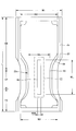
- the absorber 23 extends from the front portion F2 to the rear portion B2, and in the illustrated form, a predetermined portion in the middle in the front-rear direction including the crotch portion C2 is formed as a narrow neck portion 23n.
- the minimum width W5 of the constricted portion 23n is preferably about 50 to 65% of the width W2 of the non-constricted portion located before and after the constricted portion 23n.
- the front end of the constricted portion 23n is preferably located in the range of 10 to 25%.
- the rear end of the constricted portion 23n is preferably located in the range of 40 to 65%. Further, it is preferable that the portion (minimum width portion) having the minimum width W5 of the constricted portion 23n is located in the range of 25 to 30%.
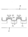
- a slit 40 having a predetermined width extends in the front-rear direction in the front-rear direction region corresponding to at least the crotch portion C2 of the absorbent body 23. It is formed. Further, as shown in FIGS. 4 to 6C, the top sheet 22 has a depressed portion 30 that has fallen into the slit 40 of the absorber 23. As shown in FIG. 5A to FIG. 6C, a convex portion 31 is formed on at least a part of the depressed portion 30 on the surface of the top sheet 22.
- a plurality of convex portions 31 are arranged in a matrix or a staggered pattern on at least a part of the depressed portion 30.
- the front side portions of the intermediate sheet 25 and the packaging sheet 26 exist between the top sheet 22 and the absorber 23, the front side portions of the intermediate sheet 25 and the packaging sheet 26 are also together with the top sheet 22. It falls into the slit 40.
- other than the top sheet 22 can be omitted.
- the length 40L in the front-rear direction is not particularly limited. Therefore, the slit 40 can be provided over the entire front-rear direction of the absorber 23. It is desirable to extend from the crotch side end to the crotch side end of the rear part B2.
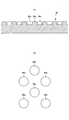
- FIG. 7, FIG. 9A and FIG. 9B are plan views showing other examples of the absorber 23 in the present embodiment.
- the part of the rear side of the slit 40 can also be bent toward the width direction outer side (the front side can also be bent similarly). More specifically, when the front end of the disposable diaper 200 is 0% and the rear end of the disposable diaper 200 is 100%, the front end of the slit 40 is preferably located in a range of 15 to 30%. The rear end of 40 is preferably located in the range of 40 to 70%.
- the front and rear ends of the slit 40 do not penetrate through the periphery of the absorber 23. However, as in the example shown in FIG. You may be allowed to reach the periphery. Note that, in a form in which both front and rear ends of the slit 40 reach the side edges of the absorber 23, the portion on the side of the slit 40 is separate from the portion between the slits 40.
- a center slit 41 can be added at the center in the width direction as shown in FIG.
- the position in the width direction of the slit 40 is preferably symmetrical, and the interval 40D of the slit 40 is usually about 10 to 30% of the minimum width W5 of the constricted portion 23n of the absorber 23. preferable.
- the number of slits 40 is not limited, and only one slit 40 can be provided along the front-rear direction at the center in the width direction as shown in FIGS.
- the width 40W of the slit 40 is not particularly limited as long as the opposing side walls are spaced apart from each other. However, in a normal case, the width 40W is desirably about 10 to 20% of the minimum width W5 of the constricted portion 23n of the absorber 23. In the case of an adult product, it can be about 5 to 32 mm.
- FIG. 5A is a cross-sectional view schematically showing a developed state of the pad type disposable diaper 200 in the present embodiment.
- FIG.5 (b) is sectional drawing which shows roughly the mounting state of the pad type disposable diaper 200 in this embodiment.
- FIG.5 (c) is a principal part schematic plan view of the mounting state of the pad type disposable diaper 200 in this embodiment.
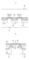
- FIGS. 6A to 6C show other examples.
- Fig.6 (a) is sectional drawing which shows schematically the expansion
- FIG.6 (b) is sectional drawing which shows roughly the mounting state of the pad type disposable diaper 200 in this embodiment.
- FIG.6 (c) is a principal part schematic plan view of the mounting state of the pad type disposable diaper 200 in this embodiment.
- the arrangement pattern of the protrusions 31 is a matrix, and in FIGS. 6 (a) to 6 (c), the arrangement pattern of the protrusions 31 is a staggered pattern (in adjacent rows). Alternate arrangement).
- the developed state shown in FIG. 5 (a) is compared with the mounted state shown in FIGS. 5 (b) and 5 (c), or FIG. 6 (a).
- the crotch portion C2 is sandwiched between the legs of the wearer in the worn state. Therefore, when the convex portion 31 is located at the bottom of the depressed portion 30 when it contracts to some extent in the width direction and approaches both side surfaces of the slit 40, it is sandwiched between the opposing side surfaces, and thus between the opposing side surfaces on the convex portion 31. Space is maintained.
- the convex portion 31 in the top sheet 22 may be provided only in the depressed portion 30, that is, only in the slit 40, or may be provided only on one side in the width direction of the slit 40. Moreover, the number of the convex parts 31 is not limited, A small number may be sufficient. However, it is difficult to manufacture by accurately aligning the position of the convex portion 31 with the position of the slit 40 of the absorber 23. Accordingly, as shown in FIG. 2 and FIG. 7, the top sheet 22 includes the sagging portion 30 and extends over a wider range 11 than in FIGS. 5 (a) to 5 (c) and FIGS. 6 (a) to 6.
- the arrangement region 11 of the protrusions 31 extends over the entire top sheet 22 in the front-rear direction as shown in FIG. 2, and is slightly protruded from the front and rear ends of the slit 40 as shown in FIG. You can also.
- the width direction in addition to arranging the protrusions 31 over the entire width of the top sheet 22, the width direction both ends of the slit 40 may slightly protrude as shown in the illustrated example.
- a row aligned in the front-rear direction of the convex portion 31 is the sagging portion.
- the absorber Even if the position in the width direction of the top sheet 22 with respect to 23 is slightly deviated at the time of manufacture or use, the row of any one of the protrusions 31 can secure the space of the slit 40 in the extending direction.
- the front-rear direction dimension 31 m of the convex portion 31 is It is preferable that the distance between the convex portions 31 arranged in the front-rear direction is larger than 32 m. Similarly, it is preferable that the width direction dimension 31c of the protrusions 31 is larger than the interval 32c of the protrusions 31 arranged in the width direction.
- the dimensions 31 m and 31 c of the protrusions 31 are small, the distances 32 m and 32 c of the protrusions 31 are too wide, or the protrusions 31 fit into the adjacent protrusions 32, the above-described space securing action is local. There is a risk that it will only be exhibited. On the other hand, if the dimensions 31 m and 31 c of the convex portions 31 are larger than the intervals 32 m and 32 c of the convex portions 31, the occupied area of the convex portions 31 becomes larger than between the convex portions 31.
- the convex portions 31 on one opposing side surface do not enter between the convex portions 31 on the other opposing side surface, and the opposing convex portions 31 are in contact with each other. Space is secured.
- the interval 32c between the protrusions 31 arranged in the width direction is 0.1 of the width direction dimension 31c of the protrusions 31. It is preferable to be 0.5 times. That is, as shown in FIGS. 11A and 11B, when the array of the protrusions 31 is a matrix array, the portion between the protrusions 31 is 32c between the protrusions 31 adjacent in the width direction. Since the (low-rigidity portion) continues most linearly in the front-rear direction, when the width of the slit 40 is narrowed, the top sheet 22 is bent at this position 32c.
- the convex portions 31 are arranged with the dimension 31c and the interval 32c, the convex portions 31 on one opposing side surface do not enter between the convex portions 31 on the other opposing side surface, and the opposing convex portions 31 contact each other. Therefore, a more preferable space securing state is obtained.
- the interval between the convex portions 31 arranged in the width direction is 0.5 of the width direction dimension of the convex portions 31. It is preferable that it is -0.9 times.
- the portion between the convex portions 31 at the center in the width direction of the convex portions 31 arranged in a zigzag in the front-rear direction ( The top sheet 22 is bent at this position Q when the width of the slit 40 is narrowed.
- the convex portions 31 are arranged with the above-described dimensions and intervals, the convex portions 31 on one opposing side surface are unlikely to enter between the convex portions 31 on the other opposing side surface, and the opposing convex portions 31 are likely to contact each other. Therefore, a more preferable space securing state is obtained.
- the specific dimensions, shape, arrangement, and structure of the convex portions 31 in the top sheet 22 are not particularly limited and can be determined as appropriate.
- An example is as follows.
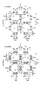
- FIGS. 10 to 13C by embossing the top sheet 22 from the back side to the front side, a large number of convex portions 31 are arranged at intervals in the width direction and the front-rear direction. can do.
- Reference numeral 32 denotes a portion between adjacent convex portions 31.
- This arrangement is arranged in a matrix as shown in FIGS. 11 (a) and 11 (b), and in a staggered manner (in adjacent rows as shown in FIGS. 10, 12 (a) and 12 (b)). The arrangement can be changed as appropriate.
- the form which provides the convex part 31 over the substantially whole top sheet 22 is assumed in the form of illustration, it adjoins the area
- the dimensions and the like of the protrusion 31 can be determined as appropriate, but as shown in FIGS. 10 to 12B, the MD (machine direction) dimension 31m of the protrusion 31 is on one side of the protrusion 31 in the MD direction. It is preferable that the center interval 80y between the top sheet joint 80 (described later) and the top sheet joint 80 located on the other side is not more than 80y, and the lower limit is preferably about 0.9 times. It is preferably about 7 to 9 mm. Similarly, the CD (cross-direction) direction dimension 31c of the convex portion 31 is equal to or less than the center interval 80x between the top sheet joint portion 80 located on one side of the convex portion 31 in the CD direction and the top sheet joint portion 80 located on the other side. The lower limit is preferably about 0.9 times, and is usually about 2.7 to 9 mm. Further, the height 31z of the convex portion 31 is preferably about 0.8 to 2 mm in a normal case.
- MD direction and CD direction in the product mean “MD direction” and “CD direction” of the processing equipment of the convex portion 31, and one of them is the front-rear direction, and the other Is the width direction.
- the MD direction in the product is the direction of fiber orientation of the nonwoven fabric of the top sheet 22.
- the fiber orientation is the direction along which the fibers of the nonwoven fabric are aligned.
- the fiber orientation can be determined from the measurement method according to the TAPPI standard method T481, the fiber orientation test method using the zero-range tensile strength, It can be discriminated by a simple measuring method for determining the orientation direction.
- the front-rear direction is the MD direction and the width direction is the CD direction, as in most products of absorbent articles.
- the arrangement interval of the protrusions 31 can be determined as appropriate. However, in the case of a matrix arrangement as shown in FIGS. 11A and 11B, the CD direction of the MD direction row of the protrusions 31 adjacent to the CD direction.
- the center interval 31x is preferably about 3 to 10 mm, and the MD direction center interval 31y of the CD direction row of the protrusions 31 adjacent in the MD direction is preferably about 3 to 10 mm.
- the CD direction center interval 31x of the MD direction row of the convex portions 31 adjacent in the CD direction is about 3 to 10 mm
- the center distance 31y in the MD direction of the CD direction row of the protrusions 31 adjacent in the MD direction is preferably about 3 to 10 mm.
- the shape of the convex portion 31 is preferably a circular dome shape, but may be an elliptical dome shape or a regular polygon dome shape.
- the convex portion 31 can be formed by embossing the top sheet 22.
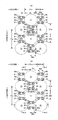
- the portion between the convex portions 31 adjacent to each other in the width direction and the front-rear direction in the top sheet 22 is joined to the intermediate sheet 25 by pressure welding, so that the width A number of top sheet joining portions 80 are formed in intermittent joining patterns in the direction and the front-rear direction.
- the top sheet joining portion 80 is also a portion that forms the bottom of the recess.
- a row in which a plurality of top sheet joining portions 80 are arranged at intervals in the CD direction is concerned. It is formed so as to cross the center position in the CD direction of the region.
- the top sheet 22 and the intermediate sheet 25 are not welded at the interval portion in the CD direction of the top sheet joining portion 80, and the top sheet 22 is a compressed portion 81 compressed from both sides in the MD direction.
- 13 (a), 13 (b) and 13 (c) correspond to the 1-1, 2-2 and 3-3 sections of FIG. 12 (b), respectively.
- the intermediate sheet 25 may be compressed integrally with the top sheet 22 or may not be compressed.
- the portions other than the top sheet joining portion 80 and the compression portion 81 may be compressed in the same manner as the interval portion (81) in the CD direction without the top sheet 22 and the intermediate sheet 25 being welded.
- T1 ⁇ T2 T1 ⁇ T2 ⁇ T3
- T1 ⁇ T2 T3 may be used, it is desirable that T1 ⁇ T2 ⁇ T3.
- a space is formed between the portion having the convex portion 31 in the top sheet 22 and the intermediate sheet 25. In this case, the back surface of the top sheet 22 and the intermediate sheet 25 may be bonded over the entire surface.
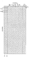
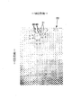
- FIG. 15 shows a sample photograph of the assembly of the top sheet 22 and the intermediate sheet 25 that adopts the pattern shown in FIGS. 10 and 12B.
- FIG. 16 is a photograph of the top sheet surface of the comparative sample.
- the convex portion 31 is clear from the comparison between the sample shown in FIG. 15 and the sample shown in FIG. Even when a vertical hook is formed at the time of forming, the top sheet joint 80 by pressure welding and the compressed part 81 compressed without welding are crossed across the vertical hook when joining to the intermediate sheet 25. Since it continues alternately in the CD direction, the top sheet joining portion 80 can be formed in a state where the warp is further extended, and this state or a state close thereto is maintained even after manufacturing. Nevertheless, since the joined portions are intermittent in the CD direction, it is possible to prevent a decrease in flexibility and a deterioration in appearance. On the other hand, in the comparative sample having the top sheet joining portion 80 that does not satisfy the above conditions, a large number of wrinkles along the MD direction are formed at intervals in the CD direction, which deteriorates the appearance.
- the bonding pattern is not particularly limited as long as a plurality of top sheet bonding portions 80 are arranged at intervals in the CD direction in the region between the convex portions 31 adjacent in the MD direction, and the CD direction interval portions are connected by the compression portion 81. .
- the top sheet joint 80 is formed at the center in the CD direction corresponding to the center in the CD direction of the protrusion 31 adjacent in the MD direction. It is preferable from the viewpoint of prevention. In this case, it is also preferable from the viewpoint of flexibility to make the area of the top sheet bonding portion 80 at the center position in the CD direction smaller than the areas of the other top sheet bonding portions 80.
- a pattern in which the top sheet bonding portion 80 is not formed at the center position in the CD direction is preferable because it becomes more flexible.
- a plurality of rows of top sheet joining portions 80 are arranged in the CD direction at intervals in the region between the convex portions 31 adjacent in the MD direction.
- a plurality of rows can be provided at intervals in the MD direction.
- the former is suitable for a pattern in which the intervals in the MD direction of the protrusions 31 are narrow as shown in FIGS. 11A and 11B in which the protrusions 31 are arranged in a matrix. This is suitable for a pattern in which the convex portions 31 have a wide interval in the MD direction as shown in FIGS.
- the interval portion in the MD direction of the top sheet joining portion 80 may be compressed in the same manner as the interval portion in the CD direction without the top sheet 22 and the intermediate sheet 25 being welded.
- the top sheet 22 and the intermediate sheet 25 are not welded and the top sheet 22 is not compressed (including non-compressed, which is not compressed at all) than the interval portion in the CD direction, more excellent flexibility and appearance can be obtained.
- each top sheet joint is not particularly limited, and may be an arbitrary shape such as an ellipse, a polygon, a star, a cloud, etc. in addition to a circle as shown in the illustrated example.
- each top sheet joint portion 80 between the convex portions 31 adjacent in the MD direction has a length 80 m in the MD direction and is adjacent to the MD direction.
- the junction points are about 0.1 to 0.4 times (usually 0.5 to 3 mm, for example) about the CD center distance 31x of the direction row.
- the CD direction interval 80d between the top sheet joining portions 80 adjacent to each other in the CD direction is about 1 to 5 times the CD length 80c of the top sheet joining portion 80 (normally 0.5 to 15 mm, for example). It is preferable that the number of the top sheet bonding portions 80 in the CD direction row is about 2 to 4.
- FIGS. 12A and 12B when the convex portions 31 are staggered, between the convex portions 31 adjacent in the CD direction are between the convex portions 31 adjacent in the MD direction. However, the same top sheet joint part 80 as between the convex parts 31 adjacent in the MD direction is provided.
- FIG. 11A and FIG. 11B in the case where the convex portions 31 are arranged in a matrix, separately from the top sheet joint portion 80 between the convex portions 31 adjacent in the MD direction, Also between the convex portions 31 adjacent to each other in the CD direction, the top sheet joining portion 80 is intermittently provided in the MD direction.
- the pattern of the top sheet joint 80 between the protrusions 31 adjacent in the CD direction is not particularly limited, but it is preferable to arrange the dotted top sheet joints 80 at intervals in the MD direction, as shown in FIG. ),
- the compression part 81 can be formed in the interval part in the MD direction similarly to the interval part in the CD direction.
- the MD direction rows of the top sheet joining portions 80 may be provided in a row at an intermediate position between the convex portions 31 adjacent to each other in the CD direction as in the illustrated example, or a plurality of rows may be provided at intervals in the CD direction.
- the size of the dot-like topsheet joint 80 is not particularly limited, but the MD direction length 80m is 0.1 to 0 of the MD direction center interval 31y of the CD direction row of the protrusions 31 adjacent in the MD direction. .4 times (usually 0.5 to 3 mm in the normal case) and the CD direction length 80c is 0.1 to 0.4 of the CD direction center interval 31x of the MD direction row of the protrusions 31 adjacent in the CD direction. It is preferably about twice (usually 0.5 to 3 mm, for example).
- the top sheet joining portion 80 is formed in an intermittent joining pattern in the width direction and the front-rear direction, and the interval in each direction can be appropriately determined.
- each top sheet between the convex portions 31 adjacent in the MD direction The CD direction joining range A3 by the joining portion 80 is about 0.3 to 1 times the CD direction center interval 31x of the MD direction row of the convex portions 31 adjacent in the CD direction (for example, 1 to 10 mm in a normal case).
- the MD direction joining range A4 by the top sheet joining portions 80 between the convex portions 31 adjacent in the CD direction is 0.3 to 0.3 of the MD direction center interval 31y of the CD direction row of the convex portions 31 adjacent in the MD direction.
- the top sheet joining portion 80 is not different from being continuous in the CD direction and MD direction, and the permeability and flexibility of the top sheet 22 may be reduced. is there.
- FIG. 14 shows a processing facility for forming the above-described convex portion. That is, this equipment includes a push roll 90, a concave roll 91 that faces the push roll 90, and a joining roll 92 that faces the concave roll 91.
- FIG. 17A and FIG. 17B are diagrams showing the push roll 90.
- FIG. 18A and FIG. 18B are diagrams showing the concave roll 91.
- the push roll 90 has a large number of push protrusions 90a formed on the peripheral surface in the arrangement pattern of the protrusions 31 described above.
- the shape of the convex part of the pushing roll 90 can be determined as appropriate, it is preferably a truncated cone shape having a cross section (for example, a circle, an ellipse, a regular polygon, etc.) that matches the shape of the convex part 31 to be formed. .
- the concave roll 91 is provided with a pressing concave portion 91a corresponding to the pressing convex portion 90a of the pressing roll 90 on the peripheral surface, and between these pressing concave portions 91a.
- the joint convex part 91b and the compression convex part 91e are provided.
- the joint convex portion 91b is a portion for forming the top sheet joint portion 80 in the joint pattern described above, and the compression convex portion 91e is the top sheet 22 and the intermediate sheet material 25S in the interval portion in the CD direction of the top sheet joint portion 80. It is a part for compressing the nonwoven fabric 22S used as the top sheet 22 in the thickness direction, without welding.
- the intermediate sheet 25 is also compressed at the same time by the compression protrusions 91e. More specifically, in the concave roll 91, in a region between the pressing concave portions 91a adjacent to each other in the roll circumferential direction, a row in which a plurality of joint convex portions 91b are arranged at intervals in the roll axial direction is a roll axis of the region. It is formed so as to cross the center position in the direction, and the interval portion in the roll axis direction of the joint convex portion 91b is a compression convex portion 91e.
- the portions other than the joint convex portion 91b, the compression convex portion 91e, and the push-in concave portion 91a are portions that do not compress the material, but may be portions that compress the same or less than the compression convex portion 91e. .
- the indentation recess 91a of the concave roll 91 may be an “open hole” that does not have a bottom surface and is large enough for the indentation convex portion to enter, and the “indentation recess 91a” includes such an “open hole”. It is.
- the size / shape / arrangement of the push-in convex part 90a in the push-in roll 90 corresponds to the inner dimension / shape / arrangement of the convex part 31 to be formed. This corresponds to the external dimensions / shape / arrangement of the convex portions 31 to be formed.
- the size / shape / arrangement of the joint convex portion 91b in the concave roll 91 corresponds to the size / shape / placement of the formed topsheet joint portion 80, and the size / shape of the compression convex portion 91e in the concave roll 91.
- the arrangement corresponds to the size, shape, and arrangement when the compression part 81 is formed.
- the MD-direction length 91m, the CD-direction length 91c, and the CD-direction interval 91d of the compression convex portion 91c in the form shown in FIG. 18B are the top sheet joining portion 80 in the form shown in FIG. MD direction length 80 m, CD direction length 80 c, and CD direction interval 80 d can be within the same range.
- FIG. 19 is an enlarged cross-sectional view of a main part showing a convex part forming step by the push roll 90 and the concave roll 91.
- the nonwoven fabric 22S to be the top sheet 22 is transported by pulling from the downstream side of the production line, and is sandwiched between the pressing roll 90 and the concave roll 91 as shown in FIG.
- the convex portion 31 is formed by embossing into the pressing concave portion 91 a of the roll 91.
- the intermediate sheet material 25S is pulled outside the nonwoven fabric to be the top sheet 22 by pulling from the downstream side of the production line.
- the non-woven fabric 22S to be the top sheet 22 and the intermediate sheet material 25S are sandwiched between the concave roll 91 and the joining roll 92, and the compression convex portion of the concave roll 91 is inserted. While being compressed between 91e and the peripheral surface of the joining roll 92, pressure welding is performed between the joining convex portion 91b of the concave roll 91 and the peripheral surface of the joining roll 92.
- seat junction part 80 is formed and the assembly body of the top sheet 22 and the intermediate sheet
- the top sheet joining portion 80 is formed in a state in which the downpipe is further extended. And that state or a state close thereto is maintained even after manufacturing.
- the assembled assembly of the processed top sheet 22 and intermediate sheet 25 can be manufactured as a disposable diaper by assembling the absorbent body and the like according to a known method.
- the nonwoven fabric to be the top sheet 22 is fed directly into the position where the push roll 90 and the concave roll 91 mesh with each other, but only the push roll 90 is wound from the tangential direction of the peripheral surface of the push roll 90.
- the nonwoven fabric to be the top sheet 22 may be fed into the concave roll 91 as it is, and then guided to be transferred to the peripheral surface of the concave roll 91.
- a configuration in which a recess recessed from the front side to the back side is provided has the same advantages.
- Such a recess can be formed by partially compressing the absorbent body as in embossing, or by partially lowering the material.
- the slit 40 tends to be crushed in the width direction, it is suitable for applying the present invention.
- Front and back (vertical) direction means a direction connecting the ventral side (front side) and back side (rear side), and “width direction” means a direction (left and right direction) orthogonal to the front and rear direction.
- Unfolded state means a state of being flattened without contraction or slack.
- Elongation rate means a value when the natural length is 100%.
- ⁇ “Weighing” is measured as follows. After the sample or test piece has been pre-dried, it is left in a test room or apparatus in a standard state (test location is temperature 20 ⁇ 5 ° C., relative humidity 65% or less) to obtain a constant weight. Pre-drying refers to making a sample or test piece constant in an environment where the relative humidity is 10 to 25% and the temperature does not exceed 50 ° C. In addition, it is not necessary to perform preliminary drying about the fiber whose official moisture content is 0.0%. A sample with a size of 200 mm ⁇ 250 mm ( ⁇ 2 mm) is cut out from the test piece in a constant weight using a rice-basis plate (200 mm ⁇ 250 mm, ⁇ 2 mm). Measure the weight of the sample, multiply it by 20, calculate the weight per square meter, and use it as the basis weight.
- the “thickness” of the top sheet 22 and the intermediate sheet 25 shown in FIGS. 10 to 20 (b) means an apparent thickness, and is measured by the method described in paragraph [0017] of Japanese Patent No. 3611838. That is, at the time of measurement, a measurement piece 30 mm long ⁇ 30 mm wide is cut out in a state where the top sheet 22 and the intermediate sheet 25 are joined. Then, a cut surface is formed by a line that is substantially parallel to the longitudinal direction [the fiber orientation direction of the nonwoven fabric (fiber assembly) constituting the top sheet 22 (flow direction during the production of the nonwoven fabric)] and passes through the top sheet joining portion 80.
- ⁇ "Thickness" of the absorber is a thickness measuring instrument from Ozaki Manufacturing Co., Ltd. (peacock, dial thickness gauge large type, model JB (measurement range 0 to 35 mm) or model K-4 (measurement range 0 to 50 mm)) Measure the sample and the thickness meter horizontally.
- Thickness other than the above is automatically measured using an automatic thickness measuring instrument (KES-G5 handy compression measurement program) under the conditions of load: 10 gf / cm 2 and pressure area: 2 cm 2 .
- KS-G5 handy compression measurement program automatic thickness measuring instrument
- test and measurement shall be performed in a test room or equipment in the standard condition (test location is temperature 20 ⁇ 5 °C, relative humidity 65% or less). .
- the dimensions of each part mean dimensions in the expanded state, not the natural length state.
- the convex portion when the interval between the concave grooves or slits is narrowed, the convex portion is located at the bottom of the depressed portion and is sandwiched between the opposing side surfaces, thereby maintaining a space between the opposing side surfaces on the convex portion.
- the convex portion when the convex portion is positioned on one of the opposing side surfaces and abuts on the other, a space is secured between the periphery of the convex portion and the opposing side surface. Therefore, the crushing of the concave groove or the slit is suppressed, and the effect of improving the diffusibility due to the slit or the concave groove is hardly inhibited.
- slit means a penetrating portion that penetrates the front and back of the absorber.
- predetermined width with respect to the slit does not mean that the width of the gap is constant, and that it does not include a concave groove or a slit that does not have a width of the gap (contacting the opposite side wall), and does not mean that the width is constant, Therefore, as long as it has a width
- the convex portion in the top sheet may be provided only in the depressed portion, that is, only in the slit or the concave groove, but it is difficult to manufacture the convex portion according to the position of the slit or concave groove of the absorber. .
- the size of the convex portion is larger than the interval between the convex portions, the area occupied by the convex portion is larger than that between the convex portions. Even if it deform
- Appendix 3 The absorbent article according to appendix 2, wherein the protrusions are arranged in a matrix, and the interval between the protrusions arranged in the width direction is 0.1 to 0.5 times the width-direction dimension of the protrusions.
- the width of the slits or recesses because the portion between the protrusions (low-rigidity portion) is the most linearly continuous in the front-rear direction between adjacent protrusion rows in the width direction.
- the top sheet bends at this position when the is narrowed. Therefore, it is preferable that the convex portions are arranged with the dimensions and intervals described in this section because the convex portions on one opposing side surface do not enter between the convex portions on the other opposing side surface, and the opposing convex portions contact each other.
- the part between the protrusions (low-rigidity part) is the most linearly continuous in the front-rear direction at the center in the width direction of the protrusions arranged zigzag in the front-rear direction.
- the top sheet bends at this position. Therefore, when the convex portions are arranged with the dimensions and intervals described in this section, the convex portions on one opposing side surface are unlikely to enter between the convex portions on the other opposing side surface, and the opposing convex portions are likely to contact each other. preferable.
- the present invention can be used for absorbent articles in general, such as disposable diapers such as pad-type disposable diapers, pants-type or tape-type disposable diapers, and sanitary napkins.
- B2 ... Rear side part, C2 ... Crotch part, F2 ... Front side part, 11 ... Convex part arrangement area, 21 ... Liquid impervious sheet, 22 ... Top sheet, 23 ... Absorber, 24 ... Solid gather, 24s ... Gather sheet 25 ... Intermediate sheet, 26 ... Packaging sheet, 27 ... Exterior sheet, 30 ... Depressed part, 31 ... Convex part, 40 ... Slit, 41 ... Other slits, 200 ... Pad type disposable diaper.
Landscapes
- Health & Medical Sciences (AREA)
- Epidemiology (AREA)
- Engineering & Computer Science (AREA)
- Biomedical Technology (AREA)
- Heart & Thoracic Surgery (AREA)
- Vascular Medicine (AREA)
- Life Sciences & Earth Sciences (AREA)
- Animal Behavior & Ethology (AREA)
- General Health & Medical Sciences (AREA)
- Public Health (AREA)
- Veterinary Medicine (AREA)
- Absorbent Articles And Supports Therefor (AREA)
Abstract
L'invention concerne un article absorbant (200) qui comprend : un corps absorbant (23) disposé dans une plage s'étendant dans la direction avant-arrière, la plage comportant une partie d'entrejambe (C2) ; et une feuille supérieure (22) recouvrant la surface externe de l'article absorbant (23). Le corps absorbant (23) a une fente (40) d'une largeur prédéterminée s'étendant au moins à travers la partie d'entrejambe (C2) dans la direction avant-arrière. La feuille supérieure (22) comprend une partie descendante (30) tombant à l'intérieur de la fente (40) du corps absorbant (23). La partie descendante (30) comporte des saillies (31) sur au moins une partie de cette dernière.
Priority Applications (4)
| Application Number | Priority Date | Filing Date | Title |
|---|---|---|---|
| KR1020187007069A KR101874291B1 (ko) | 2015-09-25 | 2016-09-05 | 흡수성 물품 |
| EP16848483.0A EP3354245B1 (fr) | 2015-09-25 | 2016-09-05 | Article absorbant |
| CN201680014596.8A CN107427401B (zh) | 2015-09-25 | 2016-09-05 | 吸收性物品 |
| US15/757,774 US10912682B2 (en) | 2015-09-25 | 2016-09-05 | Absorbent article |
Applications Claiming Priority (2)
| Application Number | Priority Date | Filing Date | Title |
|---|---|---|---|
| JP2015-188221 | 2015-09-25 | ||
| JP2015188221A JP6198076B2 (ja) | 2015-09-25 | 2015-09-25 | 吸収性物品 |
Publications (1)
| Publication Number | Publication Date |
|---|---|
| WO2017051695A1 true WO2017051695A1 (fr) | 2017-03-30 |
Family
ID=58386144
Family Applications (1)
| Application Number | Title | Priority Date | Filing Date |
|---|---|---|---|
| PCT/JP2016/075998 WO2017051695A1 (fr) | 2015-09-25 | 2016-09-05 | Article absorbant |
Country Status (7)
| Country | Link |
|---|---|
| US (1) | US10912682B2 (fr) |
| EP (1) | EP3354245B1 (fr) |
| JP (1) | JP6198076B2 (fr) |
| KR (1) | KR101874291B1 (fr) |
| CN (1) | CN107427401B (fr) |
| TW (1) | TWI712401B (fr) |
| WO (1) | WO2017051695A1 (fr) |
Cited By (1)
| Publication number | Priority date | Publication date | Assignee | Title |
|---|---|---|---|---|
| US11628098B2 (en) | 2018-06-04 | 2023-04-18 | Daio Paper Corporation | Absorbent article |
Families Citing this family (6)
| Publication number | Priority date | Publication date | Assignee | Title |
|---|---|---|---|---|
| JP6240701B2 (ja) * | 2016-03-30 | 2017-11-29 | 大王製紙株式会社 | パンツタイプ使い捨ておむつ |
| JP6360542B2 (ja) * | 2016-11-30 | 2018-07-18 | 花王株式会社 | 吸収性物品及びそれに用いる立体開孔シートの製造方法 |
| JP7064876B2 (ja) * | 2017-12-28 | 2022-05-11 | ユニ・チャーム株式会社 | 吸収性物品 |
| JP7097275B2 (ja) * | 2018-09-28 | 2022-07-07 | 花王株式会社 | 吸収性物品 |
| USD988300S1 (en) * | 2021-03-09 | 2023-06-06 | Thales Dis Ais Deutschland Gmbh | IoT module |
| USD988299S1 (en) * | 2021-06-18 | 2023-06-06 | Telit Cinterion Deutschland Gmbh | Cellular module |
Citations (5)
| Publication number | Priority date | Publication date | Assignee | Title |
|---|---|---|---|---|
| JP2620305B2 (ja) * | 1987-05-15 | 1997-06-11 | ザ、プロクター、エンド、ギャンブル、カンパニー | 吸収性パッド |
| JPH10314217A (ja) * | 1997-05-15 | 1998-12-02 | Nippon Kyushutai Gijutsu Kenkyusho:Kk | チューブ状吸収体およびそれを備えた吸収体製品 |
| JP2002531172A (ja) * | 1998-11-30 | 2002-09-24 | ザ、プロクター、エンド、ギャンブル、カンパニー | 溝を有する吸収体 |
| JP2008520401A (ja) * | 2004-11-30 | 2008-06-19 | ザ プロクター アンド ギャンブル カンパニー | 改善された防護性のために外方に凸状の長手方向中央チャネルを有する吸収性物品 |
| WO2011034180A1 (fr) * | 2009-09-18 | 2011-03-24 | ユニ・チャーム株式会社 | Article absorbant |
Family Cites Families (29)
| Publication number | Priority date | Publication date | Assignee | Title |
|---|---|---|---|---|
| US4327730A (en) * | 1979-05-04 | 1982-05-04 | The Proctor & Gamble Company | Textured thermoplastic film and product manufactured therefrom |
| US4846821A (en) * | 1987-08-24 | 1989-07-11 | The Procter & Gamble Company | Substantially fluid-impervious microbubbled polymeric web exhibiting low levels of noise when subjected to movement |
| JP3208289B2 (ja) * | 1995-08-15 | 2001-09-10 | ユニ・チャーム株式会社 | 使い捨て吸収性アンダーガーメント |
| CA2264153C (fr) | 1996-12-13 | 2012-06-05 | Japan Absorbent Technology Institute | Compositions composites hautement absorbantes, feuilles absorbantes pourvues de ces compositions, et procede d'elaboration de ces composites |
| US6563013B1 (en) * | 1998-11-30 | 2003-05-13 | The Procter & Gamble Company | Absorbent article having channel |
| JP3467429B2 (ja) * | 1999-06-09 | 2003-11-17 | ユニ・チャーム株式会社 | 体液吸収性物品の透液性表面シート |
| JP3811000B2 (ja) * | 2000-11-30 | 2006-08-16 | ユニ・チャーム株式会社 | 使い捨ておむつ |
| JP3611838B2 (ja) | 2001-12-28 | 2005-01-19 | 花王株式会社 | 吸収性物品用の表面シート |
| US20080262459A1 (en) | 2004-06-30 | 2008-10-23 | Daio Paper Corporation | Paper Diaper |
| JP4694798B2 (ja) | 2004-06-30 | 2011-06-08 | 大王製紙株式会社 | 紙おむつ |
| KR100925571B1 (ko) * | 2004-11-30 | 2009-11-06 | 더 프록터 앤드 갬블 캄파니 | 한 쌍의 후방 측부 플랩을 구비한 흡수용품 |
| JP4969101B2 (ja) | 2005-12-27 | 2012-07-04 | 大王製紙株式会社 | 吸収性物品の製造方法 |
| JP5543268B2 (ja) | 2010-05-10 | 2014-07-09 | 大王製紙株式会社 | 使い捨て吸収性物品 |
| JP5595809B2 (ja) | 2010-06-30 | 2014-09-24 | 大王製紙株式会社 | 吸収性物品 |
| JP5548056B2 (ja) | 2010-07-07 | 2014-07-16 | 花王株式会社 | 使い捨ておむつ |
| CN103269669B (zh) | 2010-12-21 | 2016-05-18 | 花王株式会社 | 吸收性物品 |
| JP5783734B2 (ja) | 2011-01-28 | 2015-09-24 | 花王株式会社 | 吸収性物品 |
| CN103619294B (zh) * | 2011-07-07 | 2015-11-25 | 花王株式会社 | 吸收性物品 |
| JP5946679B2 (ja) * | 2012-03-30 | 2016-07-06 | ユニ・チャーム株式会社 | 吸収性物品 |
| JP6099239B2 (ja) | 2012-06-11 | 2017-03-22 | 花王株式会社 | 吸収性物品 |
| JP5875157B2 (ja) | 2012-09-28 | 2016-03-02 | 花王株式会社 | 繊維シート |
| JP5980949B2 (ja) | 2012-11-30 | 2016-08-31 | 株式会社瑞光 | 複合シート材とこれを用いた使い捨て着用物品および複合シート材の製造方法と製造装置 |
| JP6195762B2 (ja) | 2013-08-23 | 2017-09-13 | ユニ・チャーム株式会社 | 吸収性物品 |
| JP6033765B2 (ja) | 2013-12-26 | 2016-11-30 | 大王製紙株式会社 | 吸収性物品の製造方法 |
| US20150250659A1 (en) | 2014-03-06 | 2015-09-10 | The Procter & Gamble Company | Multi-component topsheets |
| JP5918795B2 (ja) | 2014-03-27 | 2016-05-18 | 大王製紙株式会社 | 吸収性物品の製造方法及び吸収性物品 |
| JP5669976B1 (ja) | 2014-06-30 | 2015-02-18 | ユニ・チャーム株式会社 | 吸収性物品及び該吸収性物品を備える着用物品 |
| JP5932910B2 (ja) | 2014-07-23 | 2016-06-08 | 花王株式会社 | パンツ型使い捨ておむつ |
| JP5939293B2 (ja) | 2014-11-10 | 2016-06-22 | 王子ホールディングス株式会社 | 吸収性物品 |
-
2015
- 2015-09-25 JP JP2015188221A patent/JP6198076B2/ja active Active
-
2016
- 2016-09-05 US US15/757,774 patent/US10912682B2/en active Active
- 2016-09-05 CN CN201680014596.8A patent/CN107427401B/zh active Active
- 2016-09-05 KR KR1020187007069A patent/KR101874291B1/ko active IP Right Grant
- 2016-09-05 EP EP16848483.0A patent/EP3354245B1/fr active Active
- 2016-09-05 WO PCT/JP2016/075998 patent/WO2017051695A1/fr active Application Filing
- 2016-09-13 TW TW105129784A patent/TWI712401B/zh active
Patent Citations (5)
| Publication number | Priority date | Publication date | Assignee | Title |
|---|---|---|---|---|
| JP2620305B2 (ja) * | 1987-05-15 | 1997-06-11 | ザ、プロクター、エンド、ギャンブル、カンパニー | 吸収性パッド |
| JPH10314217A (ja) * | 1997-05-15 | 1998-12-02 | Nippon Kyushutai Gijutsu Kenkyusho:Kk | チューブ状吸収体およびそれを備えた吸収体製品 |
| JP2002531172A (ja) * | 1998-11-30 | 2002-09-24 | ザ、プロクター、エンド、ギャンブル、カンパニー | 溝を有する吸収体 |
| JP2008520401A (ja) * | 2004-11-30 | 2008-06-19 | ザ プロクター アンド ギャンブル カンパニー | 改善された防護性のために外方に凸状の長手方向中央チャネルを有する吸収性物品 |
| WO2011034180A1 (fr) * | 2009-09-18 | 2011-03-24 | ユニ・チャーム株式会社 | Article absorbant |
Cited By (1)
| Publication number | Priority date | Publication date | Assignee | Title |
|---|---|---|---|---|
| US11628098B2 (en) | 2018-06-04 | 2023-04-18 | Daio Paper Corporation | Absorbent article |
Also Published As
| Publication number | Publication date |
|---|---|
| CN107427401A (zh) | 2017-12-01 |
| US10912682B2 (en) | 2021-02-09 |
| US20180338872A1 (en) | 2018-11-29 |
| JP6198076B2 (ja) | 2017-09-20 |
| TW201711661A (zh) | 2017-04-01 |
| EP3354245A1 (fr) | 2018-08-01 |
| EP3354245A4 (fr) | 2019-06-26 |
| KR20180031053A (ko) | 2018-03-27 |
| JP2017060633A (ja) | 2017-03-30 |
| EP3354245B1 (fr) | 2020-11-18 |
| CN107427401B (zh) | 2021-08-17 |
| KR101874291B1 (ko) | 2018-07-03 |
| TWI712401B (zh) | 2020-12-11 |
Similar Documents
| Publication | Publication Date | Title |
|---|---|---|
| WO2017051695A1 (fr) | Article absorbant | |
| JP6234492B2 (ja) | パッドタイプ使い捨ておむつ | |
| TWI711435B (zh) | 拋棄式尿布 | |
| JP2017060633A5 (fr) | ||
| JP2017140251A5 (fr) | ||
| JP2017153587A5 (fr) | ||
| WO2017047429A1 (fr) | Article absorbant | |
| JP6278487B2 (ja) | 使い捨ておむつ | |
| WO2015099103A1 (fr) | Couche jetable | |
| CN110868979B (zh) | 伸缩部件和具有该伸缩部件的一次性穿着物品 | |
| CN110891538B (zh) | 伸缩部件和具有该伸缩部件的一次性穿着物品 | |
| JP2022149107A (ja) | 吸収性物品 | |
| CN110868977A (zh) | 伸缩部件、具有该伸缩部件的一次性穿着物品以及伸缩部件的制造方法 |
Legal Events
| Date | Code | Title | Description |
|---|---|---|---|
| 121 | Ep: the epo has been informed by wipo that ep was designated in this application |
Ref document number: 16848483 Country of ref document: EP Kind code of ref document: A1 |
|
| WWE | Wipo information: entry into national phase |
Ref document number: 15757774 Country of ref document: US |
|
| ENP | Entry into the national phase |
Ref document number: 20187007069 Country of ref document: KR Kind code of ref document: A |
|
| NENP | Non-entry into the national phase |
Ref country code: DE |