WO2017051695A1 - 吸収性物品 - Google Patents
吸収性物品 Download PDFInfo
- Publication number
- WO2017051695A1 WO2017051695A1 PCT/JP2016/075998 JP2016075998W WO2017051695A1 WO 2017051695 A1 WO2017051695 A1 WO 2017051695A1 JP 2016075998 W JP2016075998 W JP 2016075998W WO 2017051695 A1 WO2017051695 A1 WO 2017051695A1
- Authority
- WO
- WIPO (PCT)
- Prior art keywords
- top sheet
- convex portions
- convex
- width
- sheet
- Prior art date
Links
Images


Classifications
-
- A—HUMAN NECESSITIES
- A61—MEDICAL OR VETERINARY SCIENCE; HYGIENE
- A61F—FILTERS IMPLANTABLE INTO BLOOD VESSELS; PROSTHESES; DEVICES PROVIDING PATENCY TO, OR PREVENTING COLLAPSING OF, TUBULAR STRUCTURES OF THE BODY, e.g. STENTS; ORTHOPAEDIC, NURSING OR CONTRACEPTIVE DEVICES; FOMENTATION; TREATMENT OR PROTECTION OF EYES OR EARS; BANDAGES, DRESSINGS OR ABSORBENT PADS; FIRST-AID KITS
- A61F13/00—Bandages or dressings; Absorbent pads
- A61F13/15—Absorbent pads, e.g. sanitary towels, swabs or tampons for external or internal application to the body; Supporting or fastening means therefor; Tampon applicators
- A61F13/51—Absorbent pads, e.g. sanitary towels, swabs or tampons for external or internal application to the body; Supporting or fastening means therefor; Tampon applicators characterised by the outer layers
- A61F13/511—Topsheet, i.e. the permeable cover or layer facing the skin
- A61F13/51104—Topsheet, i.e. the permeable cover or layer facing the skin the top sheet having a three-dimensional cross-section, e.g. corrugations, embossments, recesses or projections
- A61F13/51108—Topsheet, i.e. the permeable cover or layer facing the skin the top sheet having a three-dimensional cross-section, e.g. corrugations, embossments, recesses or projections the top sheet having corrugations or embossments having one axis relatively longer than the other axis, e.g. forming channels or grooves in a longitudinal direction
-
- A—HUMAN NECESSITIES
- A61—MEDICAL OR VETERINARY SCIENCE; HYGIENE
- A61F—FILTERS IMPLANTABLE INTO BLOOD VESSELS; PROSTHESES; DEVICES PROVIDING PATENCY TO, OR PREVENTING COLLAPSING OF, TUBULAR STRUCTURES OF THE BODY, e.g. STENTS; ORTHOPAEDIC, NURSING OR CONTRACEPTIVE DEVICES; FOMENTATION; TREATMENT OR PROTECTION OF EYES OR EARS; BANDAGES, DRESSINGS OR ABSORBENT PADS; FIRST-AID KITS
- A61F13/00—Bandages or dressings; Absorbent pads
- A61F13/15—Absorbent pads, e.g. sanitary towels, swabs or tampons for external or internal application to the body; Supporting or fastening means therefor; Tampon applicators
- A61F13/53—Absorbent pads, e.g. sanitary towels, swabs or tampons for external or internal application to the body; Supporting or fastening means therefor; Tampon applicators characterised by the absorbing medium
- A61F13/534—Absorbent pads, e.g. sanitary towels, swabs or tampons for external or internal application to the body; Supporting or fastening means therefor; Tampon applicators characterised by the absorbing medium having an inhomogeneous composition through the thickness of the pad
- A61F13/537—Absorbent pads, e.g. sanitary towels, swabs or tampons for external or internal application to the body; Supporting or fastening means therefor; Tampon applicators characterised by the absorbing medium having an inhomogeneous composition through the thickness of the pad characterised by a layer facilitating or inhibiting flow in one direction or plane, e.g. a wicking layer
- A61F13/5376—Absorbent pads, e.g. sanitary towels, swabs or tampons for external or internal application to the body; Supporting or fastening means therefor; Tampon applicators characterised by the absorbing medium having an inhomogeneous composition through the thickness of the pad characterised by a layer facilitating or inhibiting flow in one direction or plane, e.g. a wicking layer characterised by the performance of the layer, e.g. acquisition rate, distribution time, transfer time
-
- A—HUMAN NECESSITIES
- A61—MEDICAL OR VETERINARY SCIENCE; HYGIENE
- A61F—FILTERS IMPLANTABLE INTO BLOOD VESSELS; PROSTHESES; DEVICES PROVIDING PATENCY TO, OR PREVENTING COLLAPSING OF, TUBULAR STRUCTURES OF THE BODY, e.g. STENTS; ORTHOPAEDIC, NURSING OR CONTRACEPTIVE DEVICES; FOMENTATION; TREATMENT OR PROTECTION OF EYES OR EARS; BANDAGES, DRESSINGS OR ABSORBENT PADS; FIRST-AID KITS
- A61F13/00—Bandages or dressings; Absorbent pads
- A61F13/15—Absorbent pads, e.g. sanitary towels, swabs or tampons for external or internal application to the body; Supporting or fastening means therefor; Tampon applicators
- A61F13/51—Absorbent pads, e.g. sanitary towels, swabs or tampons for external or internal application to the body; Supporting or fastening means therefor; Tampon applicators characterised by the outer layers
- A61F13/511—Topsheet, i.e. the permeable cover or layer facing the skin
- A61F13/51104—Topsheet, i.e. the permeable cover or layer facing the skin the top sheet having a three-dimensional cross-section, e.g. corrugations, embossments, recesses or projections
-
- A—HUMAN NECESSITIES
- A61—MEDICAL OR VETERINARY SCIENCE; HYGIENE
- A61F—FILTERS IMPLANTABLE INTO BLOOD VESSELS; PROSTHESES; DEVICES PROVIDING PATENCY TO, OR PREVENTING COLLAPSING OF, TUBULAR STRUCTURES OF THE BODY, e.g. STENTS; ORTHOPAEDIC, NURSING OR CONTRACEPTIVE DEVICES; FOMENTATION; TREATMENT OR PROTECTION OF EYES OR EARS; BANDAGES, DRESSINGS OR ABSORBENT PADS; FIRST-AID KITS
- A61F13/00—Bandages or dressings; Absorbent pads
- A61F13/15—Absorbent pads, e.g. sanitary towels, swabs or tampons for external or internal application to the body; Supporting or fastening means therefor; Tampon applicators
- A61F13/51—Absorbent pads, e.g. sanitary towels, swabs or tampons for external or internal application to the body; Supporting or fastening means therefor; Tampon applicators characterised by the outer layers
- A61F13/511—Topsheet, i.e. the permeable cover or layer facing the skin
- A61F13/513—Topsheet, i.e. the permeable cover or layer facing the skin characterised by its function or properties, e.g. stretchability, breathability, rewet, visual effect; having areas of different permeability
-
- A—HUMAN NECESSITIES
- A61—MEDICAL OR VETERINARY SCIENCE; HYGIENE
- A61F—FILTERS IMPLANTABLE INTO BLOOD VESSELS; PROSTHESES; DEVICES PROVIDING PATENCY TO, OR PREVENTING COLLAPSING OF, TUBULAR STRUCTURES OF THE BODY, e.g. STENTS; ORTHOPAEDIC, NURSING OR CONTRACEPTIVE DEVICES; FOMENTATION; TREATMENT OR PROTECTION OF EYES OR EARS; BANDAGES, DRESSINGS OR ABSORBENT PADS; FIRST-AID KITS
- A61F13/00—Bandages or dressings; Absorbent pads
- A61F13/15—Absorbent pads, e.g. sanitary towels, swabs or tampons for external or internal application to the body; Supporting or fastening means therefor; Tampon applicators
- A61F13/53—Absorbent pads, e.g. sanitary towels, swabs or tampons for external or internal application to the body; Supporting or fastening means therefor; Tampon applicators characterised by the absorbing medium
- A61F13/531—Absorbent pads, e.g. sanitary towels, swabs or tampons for external or internal application to the body; Supporting or fastening means therefor; Tampon applicators characterised by the absorbing medium having a homogeneous composition through the thickness of the pad
- A61F13/532—Absorbent pads, e.g. sanitary towels, swabs or tampons for external or internal application to the body; Supporting or fastening means therefor; Tampon applicators characterised by the absorbing medium having a homogeneous composition through the thickness of the pad inhomogeneous in the plane of the pad
-
- A—HUMAN NECESSITIES
- A61—MEDICAL OR VETERINARY SCIENCE; HYGIENE
- A61F—FILTERS IMPLANTABLE INTO BLOOD VESSELS; PROSTHESES; DEVICES PROVIDING PATENCY TO, OR PREVENTING COLLAPSING OF, TUBULAR STRUCTURES OF THE BODY, e.g. STENTS; ORTHOPAEDIC, NURSING OR CONTRACEPTIVE DEVICES; FOMENTATION; TREATMENT OR PROTECTION OF EYES OR EARS; BANDAGES, DRESSINGS OR ABSORBENT PADS; FIRST-AID KITS
- A61F13/00—Bandages or dressings; Absorbent pads
- A61F13/15—Absorbent pads, e.g. sanitary towels, swabs or tampons for external or internal application to the body; Supporting or fastening means therefor; Tampon applicators
- A61F13/15577—Apparatus or processes for manufacturing
- A61F13/15804—Plant, e.g. involving several steps
-
- A—HUMAN NECESSITIES
- A61—MEDICAL OR VETERINARY SCIENCE; HYGIENE
- A61F—FILTERS IMPLANTABLE INTO BLOOD VESSELS; PROSTHESES; DEVICES PROVIDING PATENCY TO, OR PREVENTING COLLAPSING OF, TUBULAR STRUCTURES OF THE BODY, e.g. STENTS; ORTHOPAEDIC, NURSING OR CONTRACEPTIVE DEVICES; FOMENTATION; TREATMENT OR PROTECTION OF EYES OR EARS; BANDAGES, DRESSINGS OR ABSORBENT PADS; FIRST-AID KITS
- A61F13/00—Bandages or dressings; Absorbent pads
- A61F13/15—Absorbent pads, e.g. sanitary towels, swabs or tampons for external or internal application to the body; Supporting or fastening means therefor; Tampon applicators
- A61F13/51—Absorbent pads, e.g. sanitary towels, swabs or tampons for external or internal application to the body; Supporting or fastening means therefor; Tampon applicators characterised by the outer layers
- A61F2013/51078—Absorbent pads, e.g. sanitary towels, swabs or tampons for external or internal application to the body; Supporting or fastening means therefor; Tampon applicators characterised by the outer layers being embossed
-
- A—HUMAN NECESSITIES
- A61—MEDICAL OR VETERINARY SCIENCE; HYGIENE
- A61F—FILTERS IMPLANTABLE INTO BLOOD VESSELS; PROSTHESES; DEVICES PROVIDING PATENCY TO, OR PREVENTING COLLAPSING OF, TUBULAR STRUCTURES OF THE BODY, e.g. STENTS; ORTHOPAEDIC, NURSING OR CONTRACEPTIVE DEVICES; FOMENTATION; TREATMENT OR PROTECTION OF EYES OR EARS; BANDAGES, DRESSINGS OR ABSORBENT PADS; FIRST-AID KITS
- A61F13/00—Bandages or dressings; Absorbent pads
- A61F13/15—Absorbent pads, e.g. sanitary towels, swabs or tampons for external or internal application to the body; Supporting or fastening means therefor; Tampon applicators
- A61F13/51—Absorbent pads, e.g. sanitary towels, swabs or tampons for external or internal application to the body; Supporting or fastening means therefor; Tampon applicators characterised by the outer layers
- A61F13/511—Topsheet, i.e. the permeable cover or layer facing the skin
- A61F13/513—Topsheet, i.e. the permeable cover or layer facing the skin characterised by its function or properties, e.g. stretchability, breathability, rewet, visual effect; having areas of different permeability
- A61F2013/51338—Topsheet, i.e. the permeable cover or layer facing the skin characterised by its function or properties, e.g. stretchability, breathability, rewet, visual effect; having areas of different permeability having improved touch or feeling, e.g. smooth film
-
- A—HUMAN NECESSITIES
- A61—MEDICAL OR VETERINARY SCIENCE; HYGIENE
- A61F—FILTERS IMPLANTABLE INTO BLOOD VESSELS; PROSTHESES; DEVICES PROVIDING PATENCY TO, OR PREVENTING COLLAPSING OF, TUBULAR STRUCTURES OF THE BODY, e.g. STENTS; ORTHOPAEDIC, NURSING OR CONTRACEPTIVE DEVICES; FOMENTATION; TREATMENT OR PROTECTION OF EYES OR EARS; BANDAGES, DRESSINGS OR ABSORBENT PADS; FIRST-AID KITS
- A61F13/00—Bandages or dressings; Absorbent pads
- A61F13/15—Absorbent pads, e.g. sanitary towels, swabs or tampons for external or internal application to the body; Supporting or fastening means therefor; Tampon applicators
- A61F13/53—Absorbent pads, e.g. sanitary towels, swabs or tampons for external or internal application to the body; Supporting or fastening means therefor; Tampon applicators characterised by the absorbing medium
- A61F13/534—Absorbent pads, e.g. sanitary towels, swabs or tampons for external or internal application to the body; Supporting or fastening means therefor; Tampon applicators characterised by the absorbing medium having an inhomogeneous composition through the thickness of the pad
- A61F13/537—Absorbent pads, e.g. sanitary towels, swabs or tampons for external or internal application to the body; Supporting or fastening means therefor; Tampon applicators characterised by the absorbing medium having an inhomogeneous composition through the thickness of the pad characterised by a layer facilitating or inhibiting flow in one direction or plane, e.g. a wicking layer
- A61F2013/53765—Absorbent pads, e.g. sanitary towels, swabs or tampons for external or internal application to the body; Supporting or fastening means therefor; Tampon applicators characterised by the absorbing medium having an inhomogeneous composition through the thickness of the pad characterised by a layer facilitating or inhibiting flow in one direction or plane, e.g. a wicking layer characterized by its geometry
- A61F2013/53778—Absorbent pads, e.g. sanitary towels, swabs or tampons for external or internal application to the body; Supporting or fastening means therefor; Tampon applicators characterised by the absorbing medium having an inhomogeneous composition through the thickness of the pad characterised by a layer facilitating or inhibiting flow in one direction or plane, e.g. a wicking layer characterized by its geometry with grooves
Definitions
- the present invention relates to absorbent articles such as disposable diapers and sanitary napkins.
- the absorbent article is worn with the crotch portion sandwiched between both legs of the wearer and contracted to some extent in the width direction.
- the absorber in the front-rear direction range including the crotch part is provided with a slit or a concave groove having a predetermined width extending in the front-rear direction (for example, see Patent Documents 1 and 2).
- the absorbent article in a worn state is in a state where the crotch portion is sandwiched between both legs of the wearer and contracted to some extent in the width direction as described above, so that the slits and grooves are crushed in the width direction. It was maintained, and the improvement of diffusivity was sometimes inhibited.
- This problem can also be solved by ensuring wide slits and grooves, but in that case, the amount of absorption decreases and the slit formation region in the absorber is excessively deformed by the movement of both legs.
- twists and cracks are easily generated, and the shape of the slit is liable to collapse.
- the main problem of the present invention is to suppress crushing of the slits of the absorber.
- a disposable diaper having a crotch part and a front part and a rear part extending respectively to the front side and the rear side of the crotch part
- An absorbent body provided in a front-rear direction range including the crotch portion;
- a top sheet covering the front side of the absorber, Including A groove having a predetermined width or a slit having a predetermined width extending from the front surface to the back side is extended in the front-rear direction at least in the absorber in the crotch portion,
- the top sheet has a depressed portion that falls into the concave groove or slit of the absorber, and has a convex portion at least at a part of the depressed portion.
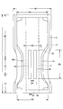
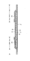
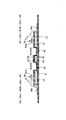
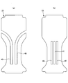
- FIG. 2 is a YY sectional view of FIG. 1.
- FIG. 2 is a sectional view taken along line XX in FIG. It is a figure which shows the pad type disposable diaper in this embodiment. It is a figure which shows the pad type disposable diaper in this embodiment. It is a top view which shows only the principal part of another example.
- FIG. 7 is a cross-sectional view of another example corresponding to the XX cross section of the form shown in FIG. 1. It is a top view which shows the other example of the absorber in this embodiment. It is a top view of a top sheet and an intermediate sheet.
- FIG.12 (b) It is explanatory drawing of the assembly equipment example of a top sheet and an intermediate sheet. It is the photograph from the upper direction of the assembly of a top sheet and an intermediate sheet. It is the photograph which image
- groin in the terminology of the present invention means a part that corresponds to the crotch of the body at the time of use, and depending on the product, from the center in the front-rear direction of the article as shown in the figure to the predetermined part on the front side.
- front part (abdominal part) means a part on the front side of the crotch part
- rear part (back side part) means a part on the rear side of the crotch part.
- a pad-type disposable diaper will be described as an example of an absorbent article.
- the pad-type disposable diaper 200 includes a crotch portion C2, and a front portion F2 and a rear portion B2 extending on both front and rear sides thereof.
- the dimensions of each part can be determined as appropriate.
- the total length (length in the front-rear direction) L is about 350 to 700 mm
- the total width W1 is about 130 to 400 mm (however, wider than the width of the absorbent surface of the diaper). it can.
- the crotch portion C2 has a length in the front-rear direction of about 10 to 150 mm
- the front portion F2 has a length in the front-rear direction of about 50 to 350 mm
- the rear portion B2 has a length in the front-rear direction of about 50 to 350 mm.
- the width C3 of the crotch portion C2 can be set to 150 cm or more, particularly about 200 to 260 cm for adults.
- the pad-type disposable diaper 200 has an absorbent body 23 interposed between an inner surface of a liquid-impermeable sheet 21 having an outer sheet 27 laminated on the outer surface and a liquid-permeable top sheet 22. It has a basic structure.
- the liquid-impermeable sheet 21 is provided on the back side of the absorber 23 so as to protrude slightly from the peripheral edge of the absorber 23.
- a sheet having moisture permeability can be used in addition to a polyethylene film or the like without impairing the water barrier from the viewpoint of preventing stuffiness.
- This water-impervious / breathable sheet is a microporous sheet obtained by, for example, melt-kneading an inorganic filler in an olefin resin such as polyethylene or polypropylene to form a sheet, and then stretching in a uniaxial or biaxial direction. Can be used.
- the outer surface of the liquid-impermeable sheet 21 is covered with an exterior sheet 27 made of a nonwoven fabric, and the exterior sheet 27 protrudes outside the periphery of the back sheet 21 with a predetermined protrusion width.
- Various nonwoven fabrics can be used as the exterior sheet 27.
- synthetic fibers such as polyethylene or polypropylene, synthetic fibers such as polyester and amide, recycled fibers such as rayon and cupra, and natural fibers such as cotton can be used.
- the front side of the absorber 23 is covered with a liquid-permeable top sheet 22.
- the absorber 23 partially protrudes from the side edge of the top sheet 22 in the illustrated form, the width of the top sheet 22 can be widened so that the side edge of the absorber 23 does not protrude.
- a perforated or non-porous nonwoven fabric or a perforated plastic sheet is used as the top sheet 22 .
- synthetic fibers such as polyethylene or polypropylene, synthetic fibers such as polyester and amide, recycled fibers such as rayon and cupra, and natural fibers such as cotton can be used.
- an intermediate sheet 25 between the top sheet 22 and the absorber 23.
- This intermediate sheet 25 is provided to prevent the urine that has been absorbed by the absorbent body 23 from returning, and uses a material having low water retention and high liquid permeability, such as various nonwoven fabrics and mesh films. Is desirable.
- the front end of the top sheet 22 is 0% and the rear end of the top sheet 22 is 100%
- the front end of the intermediate sheet 25 is preferably located in the range of 0 to 11%. It is preferably in the range of 92 to 100%.
- the width W4 of the intermediate sheet 25 is preferably about 50 to 100% of the minimum width W5 of the constricted portion 23n of the absorber 23 described later.
- the exterior sheet 27 and the liquid-permeable top sheet 22 are attached to the front and rear ends of the absorbent body 23 so as to extend to the front and rear sides, respectively. Part EF is formed.
- the exterior sheet 27 extends outward from the side edge of the absorbent body 23.
- a portion 24x on the outer side in the width direction of the gather sheet 24s that forms 24 is attached over the entire front-rear direction to constitute a side flap portion SF in which the absorber 23 does not exist.
- the liquid-impermeable sheet 21 can be extended to the side flap part SF instead of the exterior sheet 27 to form the outer surface side of the side flap part SF.
- a plastic sheet or a melt-blown nonwoven fabric can be used as a material for the gather sheet 24s.
- a nonwoven fabric that is water-repellent treated with silicon or the like is preferably used.
- a portion 24c on the center side in the width direction of the gather sheet 24s extends to the top sheet 22, and an elongated elastic member 24G is stretched along the front-rear direction at the end portion on the center side in the width direction. It is fixed with a melt adhesive or the like.
- the elongated elastic member 24G styrene rubber, olefin rubber, urethane rubber, ester rubber, polyurethane, polyethylene, polystyrene, styrene butadiene, silicon, polyester, etc., which are formed in a thread shape, a string shape, a belt shape, or the like. Ordinarily used materials can be used.
- both gather sheets 24s are fixed by being bonded to the inner surface of the article (in the illustrated form, the surface of the top sheet 22 and the inner surface of the exterior sheet 27) throughout the entire front-rear direction. Further, the gather sheets 24s are fixed so that the widthwise center portion 24c is bonded and fixed to the inner surface of the article (the surface of the top sheet 22 in the illustrated embodiment) at both ends in the front-rear direction. It is not fixed to the inner surface (the top sheet 22 surface in the illustrated form). As shown in FIG. 1, the non-fixed portion is a portion that serves as a leakage prevention wall that stands up elastically with respect to the inner surface of the article (the surface of the top sheet 22 in the illustrated embodiment). It is located at the boundary between the fixed portion 24x on the outer side in the width direction at 24s and the inner portion 24c.
- the absorbent body 23 is basically made of a pulp fiber pile, an aggregate of filaments such as cellulose acetate, or a non-woven fabric, and is obtained by mixing, adhering, etc., a superabsorbent polymer such as particulates as necessary. Can be used.
- the absorbent body 23 can be wrapped with a wrapping sheet 26 such as crepe paper as required, such as when mixing superabsorbent polymer particles.
- the shape of the absorber 23 can be set to an appropriate shape such as a strip shape in which the front portion is relatively narrower than the rear portion, a rectangular shape, or a trapezoidal shape.
- the fiber basis weight and the basis weight of the superabsorbent polymer in the absorbent body 23 can be determined as appropriate, but the fiber basis weight is preferably about 100 to 600 g / m 2, and the basis weight of the absorbent polymer is about 0 to 400 g / m 2. Is preferable.
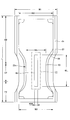
- the absorber 23 extends from the front portion F2 to the rear portion B2, and in the illustrated form, a predetermined portion in the middle in the front-rear direction including the crotch portion C2 is formed as a narrow neck portion 23n.
- the minimum width W5 of the constricted portion 23n is preferably about 50 to 65% of the width W2 of the non-constricted portion located before and after the constricted portion 23n.
- the front end of the constricted portion 23n is preferably located in the range of 10 to 25%.
- the rear end of the constricted portion 23n is preferably located in the range of 40 to 65%. Further, it is preferable that the portion (minimum width portion) having the minimum width W5 of the constricted portion 23n is located in the range of 25 to 30%.
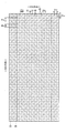
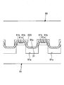
- a slit 40 having a predetermined width extends in the front-rear direction in the front-rear direction region corresponding to at least the crotch portion C2 of the absorbent body 23. It is formed. Further, as shown in FIGS. 4 to 6C, the top sheet 22 has a depressed portion 30 that has fallen into the slit 40 of the absorber 23. As shown in FIG. 5A to FIG. 6C, a convex portion 31 is formed on at least a part of the depressed portion 30 on the surface of the top sheet 22.
- a plurality of convex portions 31 are arranged in a matrix or a staggered pattern on at least a part of the depressed portion 30.
- the front side portions of the intermediate sheet 25 and the packaging sheet 26 exist between the top sheet 22 and the absorber 23, the front side portions of the intermediate sheet 25 and the packaging sheet 26 are also together with the top sheet 22. It falls into the slit 40.
- other than the top sheet 22 can be omitted.
- the length 40L in the front-rear direction is not particularly limited. Therefore, the slit 40 can be provided over the entire front-rear direction of the absorber 23. It is desirable to extend from the crotch side end to the crotch side end of the rear part B2.
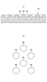
- FIG. 7, FIG. 9A and FIG. 9B are plan views showing other examples of the absorber 23 in the present embodiment.
- the part of the rear side of the slit 40 can also be bent toward the width direction outer side (the front side can also be bent similarly). More specifically, when the front end of the disposable diaper 200 is 0% and the rear end of the disposable diaper 200 is 100%, the front end of the slit 40 is preferably located in a range of 15 to 30%. The rear end of 40 is preferably located in the range of 40 to 70%.
- the front and rear ends of the slit 40 do not penetrate through the periphery of the absorber 23. However, as in the example shown in FIG. You may be allowed to reach the periphery. Note that, in a form in which both front and rear ends of the slit 40 reach the side edges of the absorber 23, the portion on the side of the slit 40 is separate from the portion between the slits 40.
- a center slit 41 can be added at the center in the width direction as shown in FIG.
- the position in the width direction of the slit 40 is preferably symmetrical, and the interval 40D of the slit 40 is usually about 10 to 30% of the minimum width W5 of the constricted portion 23n of the absorber 23. preferable.
- the number of slits 40 is not limited, and only one slit 40 can be provided along the front-rear direction at the center in the width direction as shown in FIGS.
- the width 40W of the slit 40 is not particularly limited as long as the opposing side walls are spaced apart from each other. However, in a normal case, the width 40W is desirably about 10 to 20% of the minimum width W5 of the constricted portion 23n of the absorber 23. In the case of an adult product, it can be about 5 to 32 mm.
- FIG. 5A is a cross-sectional view schematically showing a developed state of the pad type disposable diaper 200 in the present embodiment.
- FIG.5 (b) is sectional drawing which shows roughly the mounting state of the pad type disposable diaper 200 in this embodiment.
- FIG.5 (c) is a principal part schematic plan view of the mounting state of the pad type disposable diaper 200 in this embodiment.
- FIGS. 6A to 6C show other examples.
- Fig.6 (a) is sectional drawing which shows schematically the expansion
- FIG.6 (b) is sectional drawing which shows roughly the mounting state of the pad type disposable diaper 200 in this embodiment.
- FIG.6 (c) is a principal part schematic plan view of the mounting state of the pad type disposable diaper 200 in this embodiment.
- the arrangement pattern of the protrusions 31 is a matrix, and in FIGS. 6 (a) to 6 (c), the arrangement pattern of the protrusions 31 is a staggered pattern (in adjacent rows). Alternate arrangement).
- the developed state shown in FIG. 5 (a) is compared with the mounted state shown in FIGS. 5 (b) and 5 (c), or FIG. 6 (a).
- the crotch portion C2 is sandwiched between the legs of the wearer in the worn state. Therefore, when the convex portion 31 is located at the bottom of the depressed portion 30 when it contracts to some extent in the width direction and approaches both side surfaces of the slit 40, it is sandwiched between the opposing side surfaces, and thus between the opposing side surfaces on the convex portion 31. Space is maintained.
- the convex portion 31 in the top sheet 22 may be provided only in the depressed portion 30, that is, only in the slit 40, or may be provided only on one side in the width direction of the slit 40. Moreover, the number of the convex parts 31 is not limited, A small number may be sufficient. However, it is difficult to manufacture by accurately aligning the position of the convex portion 31 with the position of the slit 40 of the absorber 23. Accordingly, as shown in FIG. 2 and FIG. 7, the top sheet 22 includes the sagging portion 30 and extends over a wider range 11 than in FIGS. 5 (a) to 5 (c) and FIGS. 6 (a) to 6.
- the arrangement region 11 of the protrusions 31 extends over the entire top sheet 22 in the front-rear direction as shown in FIG. 2, and is slightly protruded from the front and rear ends of the slit 40 as shown in FIG. You can also.
- the width direction in addition to arranging the protrusions 31 over the entire width of the top sheet 22, the width direction both ends of the slit 40 may slightly protrude as shown in the illustrated example.
- a row aligned in the front-rear direction of the convex portion 31 is the sagging portion.
- the absorber Even if the position in the width direction of the top sheet 22 with respect to 23 is slightly deviated at the time of manufacture or use, the row of any one of the protrusions 31 can secure the space of the slit 40 in the extending direction.
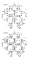
- the front-rear direction dimension 31 m of the convex portion 31 is It is preferable that the distance between the convex portions 31 arranged in the front-rear direction is larger than 32 m. Similarly, it is preferable that the width direction dimension 31c of the protrusions 31 is larger than the interval 32c of the protrusions 31 arranged in the width direction.
- the dimensions 31 m and 31 c of the protrusions 31 are small, the distances 32 m and 32 c of the protrusions 31 are too wide, or the protrusions 31 fit into the adjacent protrusions 32, the above-described space securing action is local. There is a risk that it will only be exhibited. On the other hand, if the dimensions 31 m and 31 c of the convex portions 31 are larger than the intervals 32 m and 32 c of the convex portions 31, the occupied area of the convex portions 31 becomes larger than between the convex portions 31.
- the convex portions 31 on one opposing side surface do not enter between the convex portions 31 on the other opposing side surface, and the opposing convex portions 31 are in contact with each other. Space is secured.
- the interval 32c between the protrusions 31 arranged in the width direction is 0.1 of the width direction dimension 31c of the protrusions 31. It is preferable to be 0.5 times. That is, as shown in FIGS. 11A and 11B, when the array of the protrusions 31 is a matrix array, the portion between the protrusions 31 is 32c between the protrusions 31 adjacent in the width direction. Since the (low-rigidity portion) continues most linearly in the front-rear direction, when the width of the slit 40 is narrowed, the top sheet 22 is bent at this position 32c.
- the convex portions 31 are arranged with the dimension 31c and the interval 32c, the convex portions 31 on one opposing side surface do not enter between the convex portions 31 on the other opposing side surface, and the opposing convex portions 31 contact each other. Therefore, a more preferable space securing state is obtained.
- the interval between the convex portions 31 arranged in the width direction is 0.5 of the width direction dimension of the convex portions 31. It is preferable that it is -0.9 times.
- the portion between the convex portions 31 at the center in the width direction of the convex portions 31 arranged in a zigzag in the front-rear direction ( The top sheet 22 is bent at this position Q when the width of the slit 40 is narrowed.
- the convex portions 31 are arranged with the above-described dimensions and intervals, the convex portions 31 on one opposing side surface are unlikely to enter between the convex portions 31 on the other opposing side surface, and the opposing convex portions 31 are likely to contact each other. Therefore, a more preferable space securing state is obtained.
- the specific dimensions, shape, arrangement, and structure of the convex portions 31 in the top sheet 22 are not particularly limited and can be determined as appropriate.
- An example is as follows.
- FIGS. 10 to 13C by embossing the top sheet 22 from the back side to the front side, a large number of convex portions 31 are arranged at intervals in the width direction and the front-rear direction. can do.
- Reference numeral 32 denotes a portion between adjacent convex portions 31.
- This arrangement is arranged in a matrix as shown in FIGS. 11 (a) and 11 (b), and in a staggered manner (in adjacent rows as shown in FIGS. 10, 12 (a) and 12 (b)). The arrangement can be changed as appropriate.
- the form which provides the convex part 31 over the substantially whole top sheet 22 is assumed in the form of illustration, it adjoins the area
- the dimensions and the like of the protrusion 31 can be determined as appropriate, but as shown in FIGS. 10 to 12B, the MD (machine direction) dimension 31m of the protrusion 31 is on one side of the protrusion 31 in the MD direction. It is preferable that the center interval 80y between the top sheet joint 80 (described later) and the top sheet joint 80 located on the other side is not more than 80y, and the lower limit is preferably about 0.9 times. It is preferably about 7 to 9 mm. Similarly, the CD (cross-direction) direction dimension 31c of the convex portion 31 is equal to or less than the center interval 80x between the top sheet joint portion 80 located on one side of the convex portion 31 in the CD direction and the top sheet joint portion 80 located on the other side. The lower limit is preferably about 0.9 times, and is usually about 2.7 to 9 mm. Further, the height 31z of the convex portion 31 is preferably about 0.8 to 2 mm in a normal case.
- MD direction and CD direction in the product mean “MD direction” and “CD direction” of the processing equipment of the convex portion 31, and one of them is the front-rear direction, and the other Is the width direction.
- the MD direction in the product is the direction of fiber orientation of the nonwoven fabric of the top sheet 22.
- the fiber orientation is the direction along which the fibers of the nonwoven fabric are aligned.
- the fiber orientation can be determined from the measurement method according to the TAPPI standard method T481, the fiber orientation test method using the zero-range tensile strength, It can be discriminated by a simple measuring method for determining the orientation direction.
- the front-rear direction is the MD direction and the width direction is the CD direction, as in most products of absorbent articles.
- the arrangement interval of the protrusions 31 can be determined as appropriate. However, in the case of a matrix arrangement as shown in FIGS. 11A and 11B, the CD direction of the MD direction row of the protrusions 31 adjacent to the CD direction.
- the center interval 31x is preferably about 3 to 10 mm, and the MD direction center interval 31y of the CD direction row of the protrusions 31 adjacent in the MD direction is preferably about 3 to 10 mm.
- the CD direction center interval 31x of the MD direction row of the convex portions 31 adjacent in the CD direction is about 3 to 10 mm
- the center distance 31y in the MD direction of the CD direction row of the protrusions 31 adjacent in the MD direction is preferably about 3 to 10 mm.
- the shape of the convex portion 31 is preferably a circular dome shape, but may be an elliptical dome shape or a regular polygon dome shape.
- the convex portion 31 can be formed by embossing the top sheet 22.
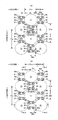
- the portion between the convex portions 31 adjacent to each other in the width direction and the front-rear direction in the top sheet 22 is joined to the intermediate sheet 25 by pressure welding, so that the width A number of top sheet joining portions 80 are formed in intermittent joining patterns in the direction and the front-rear direction.
- the top sheet joining portion 80 is also a portion that forms the bottom of the recess.
- a row in which a plurality of top sheet joining portions 80 are arranged at intervals in the CD direction is concerned. It is formed so as to cross the center position in the CD direction of the region.
- the top sheet 22 and the intermediate sheet 25 are not welded at the interval portion in the CD direction of the top sheet joining portion 80, and the top sheet 22 is a compressed portion 81 compressed from both sides in the MD direction.
- 13 (a), 13 (b) and 13 (c) correspond to the 1-1, 2-2 and 3-3 sections of FIG. 12 (b), respectively.
- the intermediate sheet 25 may be compressed integrally with the top sheet 22 or may not be compressed.
- the portions other than the top sheet joining portion 80 and the compression portion 81 may be compressed in the same manner as the interval portion (81) in the CD direction without the top sheet 22 and the intermediate sheet 25 being welded.
- T1 ⁇ T2 T1 ⁇ T2 ⁇ T3
- T1 ⁇ T2 T3 may be used, it is desirable that T1 ⁇ T2 ⁇ T3.
- a space is formed between the portion having the convex portion 31 in the top sheet 22 and the intermediate sheet 25. In this case, the back surface of the top sheet 22 and the intermediate sheet 25 may be bonded over the entire surface.
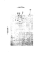
- FIG. 15 shows a sample photograph of the assembly of the top sheet 22 and the intermediate sheet 25 that adopts the pattern shown in FIGS. 10 and 12B.
- FIG. 16 is a photograph of the top sheet surface of the comparative sample.
- the convex portion 31 is clear from the comparison between the sample shown in FIG. 15 and the sample shown in FIG. Even when a vertical hook is formed at the time of forming, the top sheet joint 80 by pressure welding and the compressed part 81 compressed without welding are crossed across the vertical hook when joining to the intermediate sheet 25. Since it continues alternately in the CD direction, the top sheet joining portion 80 can be formed in a state where the warp is further extended, and this state or a state close thereto is maintained even after manufacturing. Nevertheless, since the joined portions are intermittent in the CD direction, it is possible to prevent a decrease in flexibility and a deterioration in appearance. On the other hand, in the comparative sample having the top sheet joining portion 80 that does not satisfy the above conditions, a large number of wrinkles along the MD direction are formed at intervals in the CD direction, which deteriorates the appearance.
- the bonding pattern is not particularly limited as long as a plurality of top sheet bonding portions 80 are arranged at intervals in the CD direction in the region between the convex portions 31 adjacent in the MD direction, and the CD direction interval portions are connected by the compression portion 81. .
- the top sheet joint 80 is formed at the center in the CD direction corresponding to the center in the CD direction of the protrusion 31 adjacent in the MD direction. It is preferable from the viewpoint of prevention. In this case, it is also preferable from the viewpoint of flexibility to make the area of the top sheet bonding portion 80 at the center position in the CD direction smaller than the areas of the other top sheet bonding portions 80.
- a pattern in which the top sheet bonding portion 80 is not formed at the center position in the CD direction is preferable because it becomes more flexible.
- a plurality of rows of top sheet joining portions 80 are arranged in the CD direction at intervals in the region between the convex portions 31 adjacent in the MD direction.
- a plurality of rows can be provided at intervals in the MD direction.
- the former is suitable for a pattern in which the intervals in the MD direction of the protrusions 31 are narrow as shown in FIGS. 11A and 11B in which the protrusions 31 are arranged in a matrix. This is suitable for a pattern in which the convex portions 31 have a wide interval in the MD direction as shown in FIGS.
- the interval portion in the MD direction of the top sheet joining portion 80 may be compressed in the same manner as the interval portion in the CD direction without the top sheet 22 and the intermediate sheet 25 being welded.
- the top sheet 22 and the intermediate sheet 25 are not welded and the top sheet 22 is not compressed (including non-compressed, which is not compressed at all) than the interval portion in the CD direction, more excellent flexibility and appearance can be obtained.
- each top sheet joint is not particularly limited, and may be an arbitrary shape such as an ellipse, a polygon, a star, a cloud, etc. in addition to a circle as shown in the illustrated example.
- each top sheet joint portion 80 between the convex portions 31 adjacent in the MD direction has a length 80 m in the MD direction and is adjacent to the MD direction.
- the junction points are about 0.1 to 0.4 times (usually 0.5 to 3 mm, for example) about the CD center distance 31x of the direction row.
- the CD direction interval 80d between the top sheet joining portions 80 adjacent to each other in the CD direction is about 1 to 5 times the CD length 80c of the top sheet joining portion 80 (normally 0.5 to 15 mm, for example). It is preferable that the number of the top sheet bonding portions 80 in the CD direction row is about 2 to 4.
- FIGS. 12A and 12B when the convex portions 31 are staggered, between the convex portions 31 adjacent in the CD direction are between the convex portions 31 adjacent in the MD direction. However, the same top sheet joint part 80 as between the convex parts 31 adjacent in the MD direction is provided.
- FIG. 11A and FIG. 11B in the case where the convex portions 31 are arranged in a matrix, separately from the top sheet joint portion 80 between the convex portions 31 adjacent in the MD direction, Also between the convex portions 31 adjacent to each other in the CD direction, the top sheet joining portion 80 is intermittently provided in the MD direction.
- the pattern of the top sheet joint 80 between the protrusions 31 adjacent in the CD direction is not particularly limited, but it is preferable to arrange the dotted top sheet joints 80 at intervals in the MD direction, as shown in FIG. ),
- the compression part 81 can be formed in the interval part in the MD direction similarly to the interval part in the CD direction.
- the MD direction rows of the top sheet joining portions 80 may be provided in a row at an intermediate position between the convex portions 31 adjacent to each other in the CD direction as in the illustrated example, or a plurality of rows may be provided at intervals in the CD direction.
- the size of the dot-like topsheet joint 80 is not particularly limited, but the MD direction length 80m is 0.1 to 0 of the MD direction center interval 31y of the CD direction row of the protrusions 31 adjacent in the MD direction. .4 times (usually 0.5 to 3 mm in the normal case) and the CD direction length 80c is 0.1 to 0.4 of the CD direction center interval 31x of the MD direction row of the protrusions 31 adjacent in the CD direction. It is preferably about twice (usually 0.5 to 3 mm, for example).
- the top sheet joining portion 80 is formed in an intermittent joining pattern in the width direction and the front-rear direction, and the interval in each direction can be appropriately determined.
- each top sheet between the convex portions 31 adjacent in the MD direction The CD direction joining range A3 by the joining portion 80 is about 0.3 to 1 times the CD direction center interval 31x of the MD direction row of the convex portions 31 adjacent in the CD direction (for example, 1 to 10 mm in a normal case).
- the MD direction joining range A4 by the top sheet joining portions 80 between the convex portions 31 adjacent in the CD direction is 0.3 to 0.3 of the MD direction center interval 31y of the CD direction row of the convex portions 31 adjacent in the MD direction.
- the top sheet joining portion 80 is not different from being continuous in the CD direction and MD direction, and the permeability and flexibility of the top sheet 22 may be reduced. is there.
- FIG. 14 shows a processing facility for forming the above-described convex portion. That is, this equipment includes a push roll 90, a concave roll 91 that faces the push roll 90, and a joining roll 92 that faces the concave roll 91.
- FIG. 17A and FIG. 17B are diagrams showing the push roll 90.
- FIG. 18A and FIG. 18B are diagrams showing the concave roll 91.
- the push roll 90 has a large number of push protrusions 90a formed on the peripheral surface in the arrangement pattern of the protrusions 31 described above.
- the shape of the convex part of the pushing roll 90 can be determined as appropriate, it is preferably a truncated cone shape having a cross section (for example, a circle, an ellipse, a regular polygon, etc.) that matches the shape of the convex part 31 to be formed. .
- the concave roll 91 is provided with a pressing concave portion 91a corresponding to the pressing convex portion 90a of the pressing roll 90 on the peripheral surface, and between these pressing concave portions 91a.
- the joint convex part 91b and the compression convex part 91e are provided.
- the joint convex portion 91b is a portion for forming the top sheet joint portion 80 in the joint pattern described above, and the compression convex portion 91e is the top sheet 22 and the intermediate sheet material 25S in the interval portion in the CD direction of the top sheet joint portion 80. It is a part for compressing the nonwoven fabric 22S used as the top sheet 22 in the thickness direction, without welding.
- the intermediate sheet 25 is also compressed at the same time by the compression protrusions 91e. More specifically, in the concave roll 91, in a region between the pressing concave portions 91a adjacent to each other in the roll circumferential direction, a row in which a plurality of joint convex portions 91b are arranged at intervals in the roll axial direction is a roll axis of the region. It is formed so as to cross the center position in the direction, and the interval portion in the roll axis direction of the joint convex portion 91b is a compression convex portion 91e.
- the portions other than the joint convex portion 91b, the compression convex portion 91e, and the push-in concave portion 91a are portions that do not compress the material, but may be portions that compress the same or less than the compression convex portion 91e. .
- the indentation recess 91a of the concave roll 91 may be an “open hole” that does not have a bottom surface and is large enough for the indentation convex portion to enter, and the “indentation recess 91a” includes such an “open hole”. It is.
- the size / shape / arrangement of the push-in convex part 90a in the push-in roll 90 corresponds to the inner dimension / shape / arrangement of the convex part 31 to be formed. This corresponds to the external dimensions / shape / arrangement of the convex portions 31 to be formed.
- the size / shape / arrangement of the joint convex portion 91b in the concave roll 91 corresponds to the size / shape / placement of the formed topsheet joint portion 80, and the size / shape of the compression convex portion 91e in the concave roll 91.
- the arrangement corresponds to the size, shape, and arrangement when the compression part 81 is formed.
- the MD-direction length 91m, the CD-direction length 91c, and the CD-direction interval 91d of the compression convex portion 91c in the form shown in FIG. 18B are the top sheet joining portion 80 in the form shown in FIG. MD direction length 80 m, CD direction length 80 c, and CD direction interval 80 d can be within the same range.
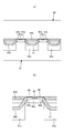
- FIG. 19 is an enlarged cross-sectional view of a main part showing a convex part forming step by the push roll 90 and the concave roll 91.
- the nonwoven fabric 22S to be the top sheet 22 is transported by pulling from the downstream side of the production line, and is sandwiched between the pressing roll 90 and the concave roll 91 as shown in FIG.
- the convex portion 31 is formed by embossing into the pressing concave portion 91 a of the roll 91.
- the intermediate sheet material 25S is pulled outside the nonwoven fabric to be the top sheet 22 by pulling from the downstream side of the production line.
- the non-woven fabric 22S to be the top sheet 22 and the intermediate sheet material 25S are sandwiched between the concave roll 91 and the joining roll 92, and the compression convex portion of the concave roll 91 is inserted. While being compressed between 91e and the peripheral surface of the joining roll 92, pressure welding is performed between the joining convex portion 91b of the concave roll 91 and the peripheral surface of the joining roll 92.
- seat junction part 80 is formed and the assembly body of the top sheet 22 and the intermediate sheet
- the top sheet joining portion 80 is formed in a state in which the downpipe is further extended. And that state or a state close thereto is maintained even after manufacturing.
- the assembled assembly of the processed top sheet 22 and intermediate sheet 25 can be manufactured as a disposable diaper by assembling the absorbent body and the like according to a known method.
- the nonwoven fabric to be the top sheet 22 is fed directly into the position where the push roll 90 and the concave roll 91 mesh with each other, but only the push roll 90 is wound from the tangential direction of the peripheral surface of the push roll 90.
- the nonwoven fabric to be the top sheet 22 may be fed into the concave roll 91 as it is, and then guided to be transferred to the peripheral surface of the concave roll 91.
- a configuration in which a recess recessed from the front side to the back side is provided has the same advantages.
- Such a recess can be formed by partially compressing the absorbent body as in embossing, or by partially lowering the material.
- the slit 40 tends to be crushed in the width direction, it is suitable for applying the present invention.
- Front and back (vertical) direction means a direction connecting the ventral side (front side) and back side (rear side), and “width direction” means a direction (left and right direction) orthogonal to the front and rear direction.
- Unfolded state means a state of being flattened without contraction or slack.
- Elongation rate means a value when the natural length is 100%.
- ⁇ “Weighing” is measured as follows. After the sample or test piece has been pre-dried, it is left in a test room or apparatus in a standard state (test location is temperature 20 ⁇ 5 ° C., relative humidity 65% or less) to obtain a constant weight. Pre-drying refers to making a sample or test piece constant in an environment where the relative humidity is 10 to 25% and the temperature does not exceed 50 ° C. In addition, it is not necessary to perform preliminary drying about the fiber whose official moisture content is 0.0%. A sample with a size of 200 mm ⁇ 250 mm ( ⁇ 2 mm) is cut out from the test piece in a constant weight using a rice-basis plate (200 mm ⁇ 250 mm, ⁇ 2 mm). Measure the weight of the sample, multiply it by 20, calculate the weight per square meter, and use it as the basis weight.
- the “thickness” of the top sheet 22 and the intermediate sheet 25 shown in FIGS. 10 to 20 (b) means an apparent thickness, and is measured by the method described in paragraph [0017] of Japanese Patent No. 3611838. That is, at the time of measurement, a measurement piece 30 mm long ⁇ 30 mm wide is cut out in a state where the top sheet 22 and the intermediate sheet 25 are joined. Then, a cut surface is formed by a line that is substantially parallel to the longitudinal direction [the fiber orientation direction of the nonwoven fabric (fiber assembly) constituting the top sheet 22 (flow direction during the production of the nonwoven fabric)] and passes through the top sheet joining portion 80.
- ⁇ "Thickness" of the absorber is a thickness measuring instrument from Ozaki Manufacturing Co., Ltd. (peacock, dial thickness gauge large type, model JB (measurement range 0 to 35 mm) or model K-4 (measurement range 0 to 50 mm)) Measure the sample and the thickness meter horizontally.
- Thickness other than the above is automatically measured using an automatic thickness measuring instrument (KES-G5 handy compression measurement program) under the conditions of load: 10 gf / cm 2 and pressure area: 2 cm 2 .
- KS-G5 handy compression measurement program automatic thickness measuring instrument
- test and measurement shall be performed in a test room or equipment in the standard condition (test location is temperature 20 ⁇ 5 °C, relative humidity 65% or less). .
- the dimensions of each part mean dimensions in the expanded state, not the natural length state.
- the convex portion when the interval between the concave grooves or slits is narrowed, the convex portion is located at the bottom of the depressed portion and is sandwiched between the opposing side surfaces, thereby maintaining a space between the opposing side surfaces on the convex portion.
- the convex portion when the convex portion is positioned on one of the opposing side surfaces and abuts on the other, a space is secured between the periphery of the convex portion and the opposing side surface. Therefore, the crushing of the concave groove or the slit is suppressed, and the effect of improving the diffusibility due to the slit or the concave groove is hardly inhibited.
- slit means a penetrating portion that penetrates the front and back of the absorber.
- predetermined width with respect to the slit does not mean that the width of the gap is constant, and that it does not include a concave groove or a slit that does not have a width of the gap (contacting the opposite side wall), and does not mean that the width is constant, Therefore, as long as it has a width
- the convex portion in the top sheet may be provided only in the depressed portion, that is, only in the slit or the concave groove, but it is difficult to manufacture the convex portion according to the position of the slit or concave groove of the absorber. .
- the size of the convex portion is larger than the interval between the convex portions, the area occupied by the convex portion is larger than that between the convex portions. Even if it deform
- Appendix 3 The absorbent article according to appendix 2, wherein the protrusions are arranged in a matrix, and the interval between the protrusions arranged in the width direction is 0.1 to 0.5 times the width-direction dimension of the protrusions.
- the width of the slits or recesses because the portion between the protrusions (low-rigidity portion) is the most linearly continuous in the front-rear direction between adjacent protrusion rows in the width direction.
- the top sheet bends at this position when the is narrowed. Therefore, it is preferable that the convex portions are arranged with the dimensions and intervals described in this section because the convex portions on one opposing side surface do not enter between the convex portions on the other opposing side surface, and the opposing convex portions contact each other.
- the part between the protrusions (low-rigidity part) is the most linearly continuous in the front-rear direction at the center in the width direction of the protrusions arranged zigzag in the front-rear direction.
- the top sheet bends at this position. Therefore, when the convex portions are arranged with the dimensions and intervals described in this section, the convex portions on one opposing side surface are unlikely to enter between the convex portions on the other opposing side surface, and the opposing convex portions are likely to contact each other. preferable.
- the present invention can be used for absorbent articles in general, such as disposable diapers such as pad-type disposable diapers, pants-type or tape-type disposable diapers, and sanitary napkins.
- B2 ... Rear side part, C2 ... Crotch part, F2 ... Front side part, 11 ... Convex part arrangement area, 21 ... Liquid impervious sheet, 22 ... Top sheet, 23 ... Absorber, 24 ... Solid gather, 24s ... Gather sheet 25 ... Intermediate sheet, 26 ... Packaging sheet, 27 ... Exterior sheet, 30 ... Depressed part, 31 ... Convex part, 40 ... Slit, 41 ... Other slits, 200 ... Pad type disposable diaper.
Landscapes
- Health & Medical Sciences (AREA)
- Epidemiology (AREA)
- Engineering & Computer Science (AREA)
- Biomedical Technology (AREA)
- Heart & Thoracic Surgery (AREA)
- Vascular Medicine (AREA)
- Life Sciences & Earth Sciences (AREA)
- Animal Behavior & Ethology (AREA)
- General Health & Medical Sciences (AREA)
- Public Health (AREA)
- Veterinary Medicine (AREA)
- Absorbent Articles And Supports Therefor (AREA)
Abstract
吸収性物品(200)は、股間部(C2)を含む前後方向範囲に設けられた吸収体(23)と、この吸収体(23)の表側を覆うトップシート(22)とを有しており、少なくとも股間部(C2)における吸収体(23)に、所定幅のスリット(40)が前後方向に延在されており、トップシート(22)は吸収体(23)のスリット(40)内に落ち込んだ落ち込み部分(30)を有しており、落ち込み部分(30)の少なくとも一部に凸部(31)を有している。
Description
本発明は、使い捨ておむつや生理用ナプキン等の吸収性物品に関する。
吸収性物品は、股間部が装着者の両脚の間に挟まれ、幅方向にある程度収縮した状態で装着される。この際、排泄位置からの前後方向の拡散性を向上させる目的で、股間部を含む前後方向範囲における吸収体に、前後方向に延びる所定幅のスリットや凹溝を設けることが知られている(例えば特許文献1、2参照)。
しかしながら、装着状態の吸収性物品は、前述のように股間部が装着者の両脚の間に挟まれ、幅方向にある程度収縮した状態となるため、スリットや凹溝が幅方向に潰れた状態に維持され、拡散性の向上が阻害されることがあった。この問題点は、スリットや凹溝の幅を広く確保することで解決することもできるが、その場合には、吸収量が低下するとともに、吸収体におけるスリット形成領域が両脚の動きにより過度に変形しやすくなり、撚れや割れが発生したり、スリットの形状が崩れたりしやすくなるという問題点があった。
そこで、本発明の主たる課題は、吸収体のスリット等の潰れを抑制することにある。
一つの形態によれば、
股間部と、当該股間部の前側及び後側にそれぞれ延出する前側部分及び後側部分とを有している、使い捨ておむつにおいて、
前記股間部を含む前後方向範囲に設けられた吸収体と、
当該吸収体の表側を覆うトップシートと、
を含み、
少なくとも前記股間部における前記吸収体に、表面から裏側に窪む所定幅の凹溝又は所定幅のスリットが前後方向に延在されており、
前記トップシートは前記吸収体の凹溝又はスリット内に落ち込んだ落ち込み部分を有しており、前記落ち込み部分の少なくとも一部に凸部を有している、
ことを特徴とする吸収性物品が提供される。
股間部と、当該股間部の前側及び後側にそれぞれ延出する前側部分及び後側部分とを有している、使い捨ておむつにおいて、
前記股間部を含む前後方向範囲に設けられた吸収体と、
当該吸収体の表側を覆うトップシートと、
を含み、
少なくとも前記股間部における前記吸収体に、表面から裏側に窪む所定幅の凹溝又は所定幅のスリットが前後方向に延在されており、
前記トップシートは前記吸収体の凹溝又はスリット内に落ち込んだ落ち込み部分を有しており、前記落ち込み部分の少なくとも一部に凸部を有している、
ことを特徴とする吸収性物品が提供される。
以上のとおり本発明によれば、吸収体のスリット等の潰れを防止できるようになる、等の利点がもたらされる。
以下、本発明の一実施形態について添付図面を参照しながら詳説する。なお、本発明の用語のうち「股間部」とは使用時に身体の股間と対応させる部分を意味し、製品によって、図示形態のように物品の前後方向中央若しくはその近傍から前側の所定部位までの範囲であったり、物品の前後方向中央の所定範囲であったりするものである。物品の前後方向中間あるいは吸収体の前後方向中間に幅の狭いくびれ部分を有する場合は、いずれか一方又は両方のくびれ部分の最小幅部位を前後方向中央とする所定の前後方向範囲を意味する。また、「前側部分(腹側部分)」は股間部よりも前側の部分を意味し、「後側部分(背側部分)」は股間部よりも後側の部分を意味する。
以下の実施形態では、パッドタイプ使い捨ておむつを吸収性物品の一例として説明する。
図1~図4は、本発明に係るパッドタイプ使い捨ておむつ例200の一例を示す。パッドタイプ使い捨ておむつ200は、股間部C2と、その前後両側に延在する前側部分F2及び後側部分B2とを有する。各部の寸法は適宜定めることができ、例えば、物品全長(前後方向長さ)Lは350~700mm程度、全幅W1は130~400mm程度(ただし、おむつの吸収面の幅より広い)とすることができる。この場合の股間部C2の前後方向長さは10~150mm程度、前側部分F2の前後方向長さは50~350mm程度、及び後側部分B2の前後方向長さは50~350mm程度とすることができる。また、股間部C2の幅W3は、大人用の場合、150cm以上、特に200~260cm程度とすることができる。
図3に示すように、パッドタイプ使い捨ておむつ200は、外面に外装シート27が積層された液不透過性シート21の内面と、透液性トップシート22との間に、吸収体23が介在された基本構造を有している。
吸収体23の裏側には、液不透過性シート21が吸収体23の周縁より若干食み出すように設けられている。液不透過性シート21としては、ポリエチレンフィルム等の他、ムレ防止の点から遮水性を損なわずに透湿性を備えたシートも用いることができる。この遮水・透湿性シートは、例えばポリエチレンやポリプロピレン等のオレフィン樹脂中に無機充填材を溶融混練してシートを形成した後、一軸または二軸方向に延伸することにより得られる微多孔性シートを用いることができる。
また、液不透過性シート21の外面は、不織布からなる外装シート27により覆われており、この外装シート27は、所定の食み出し幅をもってバックシート21の周縁より外側に食み出している。外装シート27としては各種の不織布を用いることができる。不織布を構成する素材繊維としては、ポリエチレンまたはポリプロピレン等のオレフィン系、ポリエステル系、アミド系等の合成繊維の他、レーヨンやキュプラ等の再生繊維、綿等の天然繊維を用いることができる。
吸収体23の表側は、透液性トップシート22により覆われている。図示形態ではトップシート22の側縁から吸収体23が一部食み出しているが、吸収体23の側縁が食み出さないようにトップシート22の幅を広げることもできる。トップシート22としては、有孔または無孔の不織布や穴あきプラスチックシートなどが用いられる。不織布を構成する素材繊維としては、ポリエチレンまたはポリプロピレン等のオレフィン系、ポリエステル系、アミド系等の合成繊維の他、レーヨンやキュプラ等の再生繊維、綿等の天然繊維を用いることができる。
トップシート22と吸収体23との間には、中間シート25を介在させるのが望ましい。この中間シート25は、吸収体23により吸収した尿の逆戻りを防止するために設けられるものであり、保水性が低く、且つ透液性の高い素材、例えば各種の不織布やメッシュフィルム等を用いるのが望ましい。トップシート22の前端を0%としトップシート22の後端を100%としたとき、中間シート25の前端は0~11%の範囲に位置しているのが好ましく、中間シート25の後端は92~100%の範囲に位置しているのが好ましい。また、中間シート25の幅W4は後述する吸収体23のくびれ部分23nの最小幅W5の50~100%程度であるのが好ましい。
パッドタイプ使い捨ておむつ200の前後方向両端部では、外装シート27および透液性トップシート22が吸収体23の前後端よりも前後両側にそれぞれ延在されて貼り合わされ、吸収体23の存在しないエンドフラップ部EFが形成されている。パッドタイプ使い捨ておむつ200の両側部では、外装シート27が吸収体23の側縁よりも外側にそれぞれ延在され、この延在部からトップシート22の側部までの部分の内面には、立体ギャザー24を形成するギャザーシート24sの幅方向外側の部分24xが前後方向全体にわたり貼り付けられ、吸収体23の存在しないサイドフラップ部SFを構成している。これら貼り合わせ部分は、図1では点模様で示されており、ホットメルト接着剤、ヒートシール、超音波シールにより形成できる。外装シート27を設けない場合、外装シート27に代えて液不透過性シート21をサイドフラップ部SFまで延在させ、サイドフラップ部SFの外面側を形成することができる。
ギャザーシート24sの素材としては、プラスチックシートやメルトブローン不織布を使用することもできるが、肌への感触性の点で、不織布にシリコンなどにより撥水処理をしたものが好適に使用される。
ギャザーシート24sの幅方向中央側の部分24cはトップシート22上にまで延在しており、その幅方向中央側の端部には、細長状弾性部材24Gが前後方向に沿って伸張状態でホットメルト接着剤等により固定されている。この細長状弾性部材24Gとしては、糸状、紐状、帯状等に形成された、スチレン系ゴム、オレフィン系ゴム、ウレタン系ゴム、エステル系ゴム、ポリウレタン、ポリエチレン、ポリスチレン、スチレンブタジエン、シリコン、ポリエステル等、通常使用される素材を用いることができる。
また、両ギャザーシート24sは、幅方向外側の部分24xが前後方向全体にわたり物品内面(図示形態ではトップシート22表面および外装シート27内面)に貼り合わされて固定される。さらに、両ギャザーシート24sは、幅方向中央側の部分24cが、前後方向の両端部では物品内面(図示形態ではトップシート22表面)に貼り合わされて固定され、かつ前後方向の両端部間では物品内面(図示形態ではトップシート22表面)に固定されていない。この非固定部分は、図1に示されるように、物品内面(図示形態ではトップシート22表面)に対して弾力的に起立する漏れ防止壁となる部分であり、その起立基端24bはギャザーシート24sにおける幅方向外側の固定部分24xと内側の部分24cとの境に位置する。
吸収体23としては、パルプ繊維の積繊体、セルロースアセテート等のフィラメントの集合体、あるいは不織布を基本とし、必要に応じて粒子状等の高吸収性ポリマーを混合、固着等してなるものを用いることができる。高吸収性ポリマー粒子を混合する場合等、必要に応じて、吸収体23はクレープ紙等の包装シート26により包むことができる。また、吸収体23の形状は、相対的に前側の部分が後側の部分よりも幅狭な帯状、あるいは長方形状、台形状等、適宜の形状とすることができる。
吸収体23における繊維目付け及び高吸収性ポリマーの目付けは適宜定めることができるが、繊維目付けは100~600g/m2程度とするのが好ましく、また吸収性ポリマーの目付け0~400g/m2程度とするのが好ましい。
吸収体23は、前側部分F2から後側部分B2にかけて延在されており、図示形態では股間部C2を含む前後方向中間の所定部分が幅の狭いくびれ部分23nとして形成されている。このくびれ部分23nの最小幅W5は、くびれ部分23nの前後に位置する非くびれ部分の幅W2の50~65%程度であるのが好ましい。また、物品前端を0%とし物品後端を100%としたとき、くびれ部分23nの前端は10~25%の範囲に位置しているのが好ましい。また、くびれ部分23nの後端は40~65%の範囲に位置しているのが好ましい。また、くびれ部分23nの最小幅W5となる部位(最小幅部位)は25~30%の範囲に位置しているのが好ましい。
本実施形態におけるパッドタイプ使い捨ておむつ200において、図1及び図2に示すように、吸収体23における少なくとも股間部C2と対応する前後方向領域に、所定幅のスリット40が前後方向に延在して形成される。また、図4~図6(c)に示すように、トップシート22は吸収体23のスリット40内に落ち込んだ落ち込み部分30を有している。図5(a)~図6(c)に示すように、トップシート22表面には、この落ち込み部分30の少なくとも一部に凸部31が形成されている。具体的には、落ち込み部分30の少なくとも一部に複数の凸部31が行列状又は千鳥状に配列されている。図4に示す形態では、トップシート22と吸収体23との間に中間シート25と包装シート26の表側部分が存在するため、これら中間シート25及び包装シート26の表側部分もトップシート22とともに、スリット40内に落ち込むこととなる。ただし、トップシート22以外は省略することもできる。
スリット40は股間部C2に設けられている限り、その前後方向の長さ40Lは特に限定されず、したがって吸収体23の前後方向全体にわたり設けることもできるが、図示形態のように前側部分F2の股間側端部から後側部分B2の股間側端部まで延在させることが望ましい。
図7、図9(a)及び図9(b)は、本実施形態における吸収体23の他の例を示す平面図である。また、図9(a)に示すように、スリット40の後側の部分を幅方向外側に向かうように曲げることもできる(前側も同様に曲げることができる)。より具体的には、使い捨ておむつ200の前端を0%とし、使い捨ておむつ200の後端を100%としたとき、スリット40の前端は15~30%の範囲に位置しているのが好ましく、スリット40の後端は40~70%の範囲に位置しているのが好ましい。
図1及び図2に示した形態の吸収体23では、スリット40の前後端は吸収体23の周縁に突き抜けていないが、図9(a)に示す例のように後端(前端又は両端でもよい)を周縁に達するようにしてもよい。なお、スリット40の前後両端が吸収体23の側縁に達する形態では、スリット40よりも側方の部分はスリット40間の部分とは別体となる。
スリット40は左右両側に各1本設けるほか、図9(b)に示すように幅方向中央に中央スリット41を追加することもできる。この場合、スリット40の幅方向位置は左右対称となることが好ましく、スリット40の間隔40Dは、通常の場合、吸収体23のくびれ部分23nの最小幅W5の10~30%程度であるのが好ましい。スリット40の数は限定されず、図7及び図8に示すように幅方向中央部に前後方向に沿って一本だけ設けることもできる。
スリット40の幅40Wは、対向する側壁が離間している限り特に限定されないが、通常の場合、吸収体23のくびれ部分23nの最小幅W5の10~20%程度とすることが望ましく、具体的に大人用製品の場合5~32mm程度とすることができる。
図5(a)は、本実施形態におけるパッドタイプ使い捨ておむつ200の展開状態を概略的に示す断面図である。図5(b)は、本実施形態におけるパッドタイプ使い捨ておむつ200の装着状態を概略的に示す断面図である。図5(c)は、本実施形態におけるパッドタイプ使い捨ておむつ200の装着状態の要部概略平面図である。図6(a)~図6(c)は、他の例を示す。図6(a)は、本実施形態におけるパッドタイプ使い捨ておむつ200の展開状態を概略的に示す断面図である。図6(b)は、本実施形態におけるパッドタイプ使い捨ておむつ200の装着状態を概略的に示す断面図である。図6(c)は、本実施形態におけるパッドタイプ使い捨ておむつ200の装着状態の要部概略平面図である。図5(a)~図5(c)では、凸部31の配列様式が行列状であり、図6(a)~図6(c)では凸部31の配列様式が千鳥状(隣接列で互い違いとなる配置)である。
以上のように構成されたパッドタイプ使い捨ておむつ200では、図5(a)に示される展開状態と図5(b)及び図5(c)に示される装着状態との対比、あるいは図6(a)に示される展開状態と図6(b)及び図6(c)に示される装着状態との対比からも明らかなように、装着状態で股間部C2が装着者の両脚の間に挟まれる。そのため、幅方向にある程度収縮し、スリット40の両側面が近づくと、凸部31が落ち込み部分30の底部に位置する場合には対向側面間に挟まることにより、凸部31上の対向側面間に空間が維持される。また、凸部31が対向側面の一方に位置する場合には他方に当接することにより、凸部31の周囲と対向側面との間に空間が確保される。よって、スリット40の潰れが抑制され、スリット40による拡散性向上効果が阻害されにくいものとなる。
トップシート22における凸部31は落ち込み部分30にのみ、つまりスリット40内にのみ設けてもよく、スリット40の幅方向一方側にのみ設けてもよい。また凸部31の数は限定されず、少数でも良い。ただし、凸部31の位置を、吸収体23のスリット40の位置に正確に合わせて製造することは困難である。よって、図2及び図7に示すように、トップシート22における落ち込み部分30を含みかつこれよりも広い範囲11にわたり、図5(a)~図5(c)及び図6(a)~図6(c)に示すように、凸部31を幅方向及び前後方向にそれぞれ間隔を空けて多数配列することが望ましい。例えば、凸部31の配列領域11は、図2に示すように前後方向においてはトップシート22の全体にわたるようにする他、図7に示すように、スリット40の前後端を若干はみ出す程度とすることもできる。幅方向についても、トップシート22の全幅にわたり凸部31を配列する他、図示例のようにスリット40の幅方向両端を若干はみ出す程度とすることができる。幅方向に間隔を空けて複数のスリット40を設ける場合、図示しないが、凸部31の配列領域も幅方向に間隔を空けて複数設けることができる。
トップシート22における落ち込み部分30を含みかつこれよりも広い範囲11にわたり、凸部31を幅方向及び前後方向にそれぞれ間隔を空けて多数配列する場合、凸部31の前後方向に並ぶ列が落ち込み部分30内に一列のみ配置される形態でも良いが、図5(a)~図5(c)及び図6(a)~図6(c)に示すように複数列形成されていると、吸収体23に対するトップシート22の幅方向位置が製造時又は使用時に多少ずれてもいずれかの凸部31の列がスリット40の空間をその延存方向に確保することができるため好ましい。
また、後述する図11(a)~図12(b)に示すように、凸部31を幅方向及び前後方向にそれぞれ間隔を空けて多数配列する場合、凸部31の前後方向寸法31mが、前後方向に並ぶ凸部31の間隔32mより大きい方が好ましい。同様に、凸部31の幅方向寸法31cが、幅方向に並ぶ凸部31の間隔32cより大きい方が好ましい。凸部31の寸法31mや31cが小さく、凸部31の間隔32mや32cが広過ぎたり、凸部31が隣接凸部間32に嵌合する寸法であると、前述の空間確保作用が局所的にしか発揮されなくなるおそれがある。一方、凸部31の寸法31m及び31cが、凸部31の間隔32m及び32cより大きいと、凸部31の専有面積が凸部31間に比して大きくなるため、どのような配列であっても、また落ち込み部分30がどのように変形しても、一方の対向側面の凸部31が他方の対向側面の凸部31間に入り込まず、対向する凸部31同士が接触するため、より好ましい空間確保状態となる。
図5(a)~図5(c)に示すように、凸部31を行列状に配列する場合、幅方向に並ぶ凸部31の間隔32cが凸部31の幅方向寸法31cの0.1~0.5倍であると好ましい。すなわち、図11(a)及び図11(b)にも示すように、凸部31の配列が行列状配列の場合、幅方向に隣接する凸部31列の間32cで凸部31間の部分(低剛性の部分)が最も直線的に前後方向に連続するため、スリット40の幅が狭くなる際、この位置32cでトップシート22が折れ曲がる。このとき、上記寸法31c及び間隔32cで凸部31が配列されていると、一方の対向側面の凸部31が他方の対向側面の凸部31間に入り込まず、対向する凸部31同士が接触するため、より好ましい空間確保状態となる。
また、図6(a)~図6(c)に示すように、凸部31を千鳥状に配列する場合、幅方向に並ぶ凸部31の間隔が凸部31の幅方向寸法の0.5~0.9倍であると好ましい。図12(a)及び図12(b)にも示すように、凸部31の配列が千鳥状配列の場合、前後方向にジグザグに並ぶ凸部31の幅方向中央で凸部31間の部分(低剛性の部分)が最も直線的に前後方向に連続するため、スリット40の幅が狭くなる際、この位置Qでトップシート22が折れ曲がる。ここで、上記寸法及び間隔で凸部31が配列されていると、一方の対向側面の凸部31が他方の対向側面の凸部31間に入り込みにくく、対向する凸部31同士が接触しやすくなるため、より好ましい空間確保状態となる。
トップシート22における凸部31の具体的な寸法・形状・配列・構造は特に限定されず、適宜定めることができる。一例を示すと、以下のとおりである。
すなわち、図10~図13(c)に示すように、エンボス加工を用いてトップシート22を裏側から表側に押し出すことにより、幅方向及び前後方向にそれぞれ間隔を空けて多数の凸部31を配列することができる。なお符号32は隣接する凸部31間の部分を示している。この配列様式は、図11(a)及び図11(b)に示すように行列状とする他、図10、図12(a)及び図12(b)に示すように千鳥状(隣接列で互い違いとなる配置)とする等、適宜変更することができる。また、図示形態では、トップシート22のほぼ全体にわたり凸部31を設ける形態を想定しているが、前述のように少なくとも第1部分11の両側部と対応する領域、並びにその幅方向外側に隣接する領域に設けられる限り、部分的に設けることも可能であり、例えばトップシート22と中間シート25とが重なる領域のほぼ全体にわたり設けることもできる。
凸部31の寸法等は適宜定めることができるが、図10~図12(b)に示すように、凸部31のMD(machine direction)方向寸法31mは、凸部31のMD方向一方側に位置するトップシート接合部80(後述する)と他方側に位置するトップシート接合部80との中心間隔80y以下とされ、その下限は0.9倍程度であるのが好ましく、通常の場合2.7~9mm程度とすることが好ましい。同様に、凸部31のCD(cross direction)方向寸法31cは、凸部31のCD方向一方側に位置するトップシート接合部80と他方側に位置するトップシート接合部80との中心間隔80x以下とされ、その下限は0.9倍程度であるのが好ましく、通常の場合2.7~9mm程度とすることが好ましい。また、凸部31の高さ31zは、通常の場合0.8~2mm程度とすることが好ましい。
ここで、製品における「MD方向」及び「CD方向」とは、凸部31の加工設備の「MD方向」及び「CD方向」を意味し、いずれか一方が前後方向となるものであり、他方が幅方向となるものである。そして、製品におけるMD方向は、トップシート22の不織布の繊維配向の方向である。繊維配向とは、不織布の繊維が沿う方向であり、例えば、TAPPI標準法T481の零距離引張強さによる繊維配向性試験法に準じた測定方法や、前後方向及び幅方向の引張強度比から繊維配向方向を決定する簡易的測定方法により判別することができる。図示形態は、殆ど多くの吸収性物品の製品と同様に、前後方向がMD方向となり、幅方向がCD方向となるものである。
凸部31の配置間隔は適宜定めることができるが、図11(a)及び図11(b)に示すような行列状配列の場合、CD方向に隣接する凸部31のMD方向列のCD方向中心間隔31xは3~10mm程度、MD方向に隣接する凸部31のCD方向列のMD方向中心間隔31yは3~10mm程度とするのが好ましい。また、図10、図12(a)及び図12(b)に示すような千鳥状配列の場合、CD方向に隣接する凸部31のMD方向列のCD方向中心間隔31xは3~10mm程度、MD方向に隣接する凸部31のCD方向列のMD方向中心間隔31yは3~10mm程度とするのが好ましい。
凸部31の形状は、円形ドーム状とするのが好ましいが、楕円ドーム状や、正多角形ドーム状とすることも可能である。なお、凸部31はトップシート22のエンボス加工により形成することができる。
図10~図12(b)にも示すように、トップシート22における、幅方向及び前後方向に隣接する凸部31の間の部分が加圧溶着により中間シート25と接合されることにより、幅方向及び前後方向に間欠的な接合パターンで多数のトップシート接合部80が形成されている。トップシート接合部80は、凹部の底部を形成する部分でもある。本実施形態におけるトップシート22及び中間シート25の接合パターンでは、MD方向に隣接する凸部31の間の領域では、トップシート接合部80がCD方向に間隔を空けて複数並んでなる列が当該領域のCD方向中央位置を横切るように形成されている。また、そのトップシート接合部80のCD方向の間隔部分ではトップシート22及び中間シート25が溶着されずにトップシート22がそのMD方向両側よりも圧縮された圧縮部81とされている。
図13(a)、図13(b)及び図13(c)は、それぞれ、図12(b)の1-1断面、2-2断面及び3-3断面に対応する。圧縮部81においてはトップシート22が圧縮される限り、中間シート25はトップシート22と一体的に圧縮されていても、圧縮されていなくても良い。また、トップシート接合部80及び圧縮部81以外の部分は、トップシート22及び中間シート25が溶着されずかつCD方向の間隔部分(81)と同様に圧縮されていても良いが、トップシート22及び中間シート25が溶着されずかつCD方向の間隔部分よりもトップシート22が圧縮されていない(全く圧縮されない非圧縮も含む)ことが望ましい。
つまり、トップシート22におけるトップシート接合部80の厚みをT1とし、圧縮部81の厚みをT2とし、トップシート接合部80及び圧縮部81以外の部分の厚みをT3としたとき、T1<T2=T3でも良いが、T1<T2<T3となるのが望ましい。さらに、図13(a)~図13(c)に示した形態では、トップシート22における凸部31を有する部分と中間シート25との間に空間が形成されているが、このような空間が形成されていなくても良く、この場合トップシート22の裏面と中間シート25とが全面にわたり接着されていても良い。
図15は、図10及び図12(b)に示されるパターンを採用したトップシート22及び中間シート25の組み立て体のサンプル写真を示す。図16は、比較サンプルのトップシート表面を撮影した写真である。
このように、MD方向に隣接する凸部31の間に特徴的な接合パターンを採用することにより、図15に示すサンプルと図16に示すサンプルとの対比からも明らかなように、凸部31の形成時に縦皺が形成されたとしても、中間シート25との接合の際にその縦皺を横切るように、加圧溶着によるトップシート接合部80及び溶着されずに圧縮された圧縮部81がCD方向に交互に連続するため、縦皺をより大きく伸ばした状態でトップシート接合部80を形成することができ、その状態又はそれに近い状態が製造後においても維持されるようになる。それでいて、結果的に接合される部分はCD方向に間欠的となるため、柔軟性の低下や外観の悪化は防止することができる。これに対して、上記条件を満たさないトップシート接合部80を有する比較サンプルでは、MD方向に沿う皺がCD方向に間隔を空けて多数形成されてしまい、見栄えが悪化する。
接合パターンは、MD方向に隣接する凸部31の間の領域において、複数のトップシート接合部80がCD方向に間隔を空けて並び、そのCD方向間隔部分が圧縮部81により繋がる限り特に限定されない。例えば、図11(b)及び図12(a)に示すように、MD方向に隣接する凸部31のCD方向中央部と対応するCD方向中央位置にトップシート接合部80が形成されると皺防止の観点からは好ましい。この場合、CD方向中央位置のトップシート接合部80の面積を他のトップシート接合部80の面積よりも小さくするのも、柔軟性の観点からは好ましい。一方、例えば、図11(a)及び図12(b)に示すように当該CD方向中央位置にトップシート接合部80が形成されないパターンとすると、より柔軟性に富むようになるため好ましい。
また、図11(a)及び図11(b)に示すように、MD方向に隣接する凸部31の間の領域に、トップシート接合部80がCD方向に間隔を空けて複数並んでなる列を一列設ける他、図10、図12(a)及び図12(b)に示すように、MD方向に間隔を空けて複数列設けることもできる。前者は、凸部31が行列状に配列されている図11(a)及び図11(b)に示す形態のように凸部31のMD方向間隔が狭いパターンに適しており、後者は、凸部31が千鳥状に配列されている図10、図12(a)及び図12(b)に示す形態のように凸部31のMD方向間隔が広いパターンに適している。なお、後者の形態において、トップシート接合部80のMD方向の間隔部分は、トップシート22及び中間シート25が溶着されずかつCD方向の間隔部分と同様に圧縮されていても良いが、トップシート22及び中間シート25が溶着されずかつCD方向の間隔部分よりもトップシート22が圧縮されていない(全く圧縮されない非圧縮も含む)と、より優れた柔軟性及び外観を得ることができる。
個々のトップシート接合部の形状は特に限定されず、図示例のような円形の他、楕円形、多角形、星形、雲形等、任意の形状とすることができる。
トップシート接合部80の寸法は適宜定めることができるが、MD方向に隣接する凸部31の間における個々のトップシート接合部80は、MD方向長さ80mが、MD方向に隣接する凸部31のCD方向列のMD方向中心間隔31yの0.1~0.4倍(通常の場合例えば0.5~3mm)程度、かつCD方向長さ80cが、CD方向に隣接する凸部31のMD方向列のCD方向中心間隔31xの0.1~0.4倍(通常の場合例えば0.5~3mm)程度の、点状接合部であるのが好ましい。また、CD方向に隣接するトップシート接合部80のCD方向間隔80dは、トップシート接合部80のCD方向長さ80cの1~5倍(通常の場合例えば0.5~15mm)程度であるのが好ましく、CD方向列におけるトップシート接合部80の個数は2~4個程度であるのが好ましい。
また、図12(a)及び図12(b)に示すように、凸部31が千鳥状の場合には、CD方向に隣接する凸部31の間はMD方向に隣接する凸部31の間でもあるため、MD方向に隣接する凸部31の間と同様のトップシート接合部80が設けられる。一方、図11(a)及び図11(b)に示すように、凸部31が行列状配列の場合には、MD方向に隣接する凸部31の間のトップシート接合部80とは別に、CD方向に隣接する凸部31の間にも、トップシート接合部80がMD方向に間欠的に設けられる。CD方向に隣接する凸部31の間におけるトップシート接合部80のパターンは特に限定されないが、点状のトップシート接合部80をMD方向に間隔を空けて配列することが好ましく、図11(b)に示すようにMD方向の間隔部分においても、CD方向の間隔部分と同様に圧縮部81を形成することができる。このトップシート接合部80のMD方向列は、図示例のようにCD方向に隣接する凸部31の中間位置に一列設ける他、CD方向に間隔を空けて複数列設けることもできる。また、この点状のトップシート接合部80の寸法は特に限定されないが、MD方向長さ80mが、MD方向に隣接する凸部31のCD方向列のMD方向中心間隔31yの0.1~0.4倍(通常の場合例えば0.5~3mm)程度、かつCD方向長さ80cが、CD方向に隣接する凸部31のMD方向列のCD方向中心間隔31xの0.1~0.4倍(通常の場合例えば0.5~3mm)程度であるのが好ましい。
トップシート接合部80は、幅方向及び前後方向に間欠的な接合パターンで形成され、各方向の間隔は適宜定めることができるが、例えば、MD方向に隣接する凸部31の間における各トップシート接合部80によるCD方向接合範囲A3は、CD方向に隣接する凸部31のMD方向列のCD方向中心間隔31xの0.3~1倍(通常の場合例えば1~10mm)程度であるのが好ましい。また、CD方向に隣接する凸部31の間における各トップシート接合部80によるMD方向接合範囲A4は、MD方向に隣接する凸部31のCD方向列のMD方向中心間隔31yの0.3~1倍(通常の場合例えば1~10mm)程度であるのが好ましい。これらCD方向接合範囲A3及びMD方向接合範囲A4が広すぎると、トップシート接合部80がCD方向及びMD方向に連続するのと変わりなくなり、トップシート22の透過性や柔軟性が低下するおそれがある。
図14は、上述の凸部を形成するための加工設備を示している。すなわち、この設備は、押し込みロール90と、この押し込みロール90に対向する凹ロール91と、この凹ロール91に対向する接合ロール92とを備えている。図17(a)及び図17(b)は、押し込みロール90を示す図である。図18(a)及び図18(b)は、凹ロール91を示す図である。
押し込みロール90は、図17(a)及び図17(b)に示すように、周面に多数の押し込み凸部90aが前述の凸部31の配列パターンで形成されたものである。押し込みロール90の凸部の形状は適宜定めることができるが、形成する凸部31の形状に合わせた断面(例えば円形、楕円形、正多角形等)の裁頭円錐台状であるのが好ましい。
凹ロール91は、図18(a)及び図18(b)に示すように、周面に押し込みロール90の押し込み凸部90aに対応する押し込み凹部91aが設けられるとともに、これら押し込み凹部91a間に、接合凸部91b及び圧縮凸部91eが設けられたものである。接合凸部91bは前述の接合パターンにおけるトップシート接合部80を形成するための部分であり、圧縮凸部91eはトップシート接合部80のCD方向の間隔部分においてトップシート22及び中間シートの素材25Sを溶着せずにトップシート22となる不織布22Sを厚み方向に圧縮するための部分である。中間シートの素材25Sが不織布のように厚み方向に圧縮される素材である場合は、この圧縮凸部91eによって中間シート25も同時に圧縮される。より詳細には、この凹ロール91では、ロール周方向に隣接する押し込み凹部91aの間の領域では、接合凸部91bがロール軸方向に間隔を空けて複数並んでなる列が当該領域のロール軸方向中央位置を横切るように形成されるとともに、その接合凸部91bのロール軸方向の間隔部分が圧縮凸部91eとされている。接合凸部91b、圧縮凸部91e、及び押し込み凹部91a以外の部分は、素材を圧縮しない部分とされているが、圧縮凸部91eと同程度又はそれ以下の圧縮を行う部分とすることもできる。凹ロール91の押し込み凹部91aは、凸部が形成される限り、押し込み凸部が入り込む大きさの、底面がない「開孔」でもよく、「押し込み凹部91a」はかかる「開孔」も含む意味である。
押し込みロール90における押し込み凸部90aの寸法・形状・配置は、形成される凸部31の内空寸法・形状・配置と対応するものとなり、凹ロール91における押し込み凹部91aの寸法・形状・配置は、形成される凸部31の外形寸法・形状・配置と対応するものとなる。また、凹ロール91における接合凸部91bの寸法・形状・配置は、形成されるトップシート接合部80の寸法・形状・配置と対応するものとなり、凹ロール91における圧縮凸部91eの寸法・形状・配置は、圧縮部81が形成される場合にはその寸法・形状・配置と対応するものとなる。よって、これらの寸法、形状、配置については、前述した凸部31、トップシート接合部、及び圧縮部の寸法・形状・配置をと同様に変更可能である。例えば、図18(b)に示される形態における圧縮凸部91cのMD方向長さ91m、CD方向長さ91c及びCD方向間隔91dは、図12(b)に示される形態におけるトップシート接合部80のMD方向長さ80m、CD方向長さ80c、CD方向間隔80dと同様の範囲内とすることができる。
図19は、押し込みロール90及び凹ロール91による凸部形成工程を示す要部拡大断面図である。加工に際しては、トップシート22となる不織布22Sを製造ラインの下流側からの引張りにより移送しつつ、図19に示すように押し込みロール90及び凹ロール91間に挟み、押し込みロール90の凸部を凹ロール91の押し込み凹部91a内に押し込むエンボス加工により、凸部31を形成する。
しかる後、この凸部31を形成した不織布22Sをそのまま凹ロール91に巻き掛けて案内する過程で、トップシート22となる不織布の外側に、製造ラインの下流側からの引張りにより中間シートの素材25Sを送り込み、図20(a)及び図20(b)に示すようにトップシート22となる不織布22S及び中間シートの素材25Sを凹ロール91及び接合ロール92間に挟み、凹ロール91の圧縮凸部91eと接合ロール92の周面との間で圧縮しつつ、凹ロール91の接合凸部91bと接合ロール92の周面との間で加圧溶着する。これにより、トップシート接合部80を形成し、トップシート22及び中間シート25の組立て体を製造する。これにより、凸部31の形成時に、トップシート22となる不織布22SにおけるMD方向に隣接する凸部31の間に縦皺が形成されたとしても、中間シートの素材25Sとの接合の際、その縦皺を横切るように、加圧溶着部分80及び溶着されずに圧縮される圧縮部81がCD方向に交互に連続するため、縦皺をより大きく伸ばした状態でトップシート接合部80を形成することができ、その状態又はそれに近い状態が製造後においても維持されるようになる。それでいて、結果的に接合される部分はCD方向に間欠的となるため、柔軟性の低下や外観の悪化は防止することができる。なお、この原理からも理解されるように、圧縮凸部91eにより圧縮した痕跡が前述の圧縮部81として残るものはもちろん、圧縮の痕跡が殆ど又は全く残らないものも縦皺の防止効果があるものである。
加圧溶着手段としては素材を厚み方向に圧縮しつつ溶着するものであれば、ロールを加熱して素材を溶着するヒートシールの他、超音波シールを採用することもできる。加工したトップシート22及び中間シート25の組立て体は、公知の方法に従って吸収体等に対して組み付けることにより使い捨ておむつを製造することができる。
以上で説明した形態のように、凸部31の形成直後に、その皺が吸収される間があまり無い状態で中間シート25の素材と接合する加工法では、皺がより残りやすいため、前述の接合パターンを採用することが好ましい。もちろん、エンボス加工により凸部31を形成した後に、トップシート接合部80を形成するのであれば、上記3ロールの加工設備でなくても良い。また、図示例では、押し込みロール90と凹ロール91とが噛み合う位置に直接的にトップシート22となる不織布を送り込んでいるが、押し込みロール90の周面の接線方向から押し込みロール90にのみ巻き付けるようにトップシート22となる不織布を送り込み、そのまま凹ロール91との間に挟んだ後に、凹ロール91の周面に移すように案内しても良い。
また、図示形態のような吸収体23を厚さ方向に貫通するスリット40に代えて、表側から裏側に窪む凹部を設ける形態としても、同様の利点を有するものとなる。このような凹部はエンボス加工のように吸収体を部分的に圧縮することにより形成する他、素材を部分的に低目付とすることにより形成することもできる。ただし、スリット40の方が幅方向に潰れやすいため、本発明を適用するのに適している。
<明細書中の用語の説明>
明細書中で以下の用語が使用される場合、明細書中に特に記載が無い限り、以下の意味を有するものである。
明細書中で以下の用語が使用される場合、明細書中に特に記載が無い限り、以下の意味を有するものである。
・「前後(縦)方向」とは腹側(前側)と背側(後側)を結ぶ方向を意味し、「幅方向」とは前後方向と直交する方向(左右方向)を意味する。
・「展開状態」とは、収縮や弛み無く平坦に展開した状態を意味する。
・「伸長率」は、自然長を100%としたときの値を意味する。
・「目付け」は次のようにして測定されるものである。試料又は試験片を予備乾燥した後、標準状態(試験場所は、温度20±5℃、相対湿度65%以下)の試験室又は装置内に放置し、恒量になった状態にする。予備乾燥は、試料又は試験片を相対湿度10~25%、温度50℃を超えない環境で恒量にすることをいう。なお、公定水分率が0.0%の繊維については、予備乾燥を行わなくてもよい。恒量になった状態の試験片から米坪板(200mm×250mm、±2mm)を使用し、200mm×250mm(±2mm)の寸法の試料を切り取る。試料の重量を測定し、20倍して1平米あたりの重さを算出し、目付けとする。
・図10~図20(b)に示されるトップシート22及び中間シート25の「厚み」は見かけの厚みを意味し、特許第特許3611838号公報の段落[0017]記載の方法により測定する。すなわち、測定に際しては、トップシート22及び中間シート25を接合した状態で、縦30mm×横30mmの測定片を切り出す。そして、縦方向〔トップシート22を構成する不織布(繊維集合体)の繊維配向方向(不織布製造時の流れ方向)〕にほぼ平行でかつトップシート接合部80を通る線で切断面を作る。この切断面の拡大写真をキーエンス社製のデジタルマイクロスコープVHX-1000等を用いて撮影し、この拡大写真に基づいてトップシート22の見かけの最大厚みを求め、これをトップシート22の厚みとし、そのトップシート22の最大厚みの測定部位において、中間シート25の見かけの厚みを測定し、これを中間シート25の厚みとする。また、他の部位の厚み(トップシート接合部80の厚みや、圧縮部81の厚み等)、並びに凸部31の高さ31z等、断面方向の寸法は、トップシート及び中間シートの「厚み」の測定と同様にして、凸部の底部から頂部までの隆起高さを測定する。
・吸収体の「厚み」は、株式会社尾崎製作所の厚み測定器(ピーコック、ダイヤルシックネスゲージ大型タイプ、型式J-B(測定範囲0~35mm)又は型式K-4(測定範囲0~50mm))を用い、試料と厚み測定器を水平にして、測定する。
・上記以外の「厚み」は、自動厚み測定器(KES-G5 ハンディ圧縮計測プログラム)を用い、荷重:10gf/cm2、及び加圧面積:2cm2の条件下で自動測定する。
・試験や測定における環境条件についての記載が無い場合、その試験や測定は、標準状態(試験場所は、温度20±5℃、相対湿度65%以下)の試験室又は装置内で行うものとする。
・各部の寸法は、特に記載が無い限り、自然長状態ではなく展開状態における寸法を意味する。
以下、本発明の好ましい態様を付記する。
(付記1)
股間部と、股間部の前側及び後側にそれぞれ延出する前側部分及び後側部分とを有している、使い捨ておむつにおいて、
前記股間部を含む前後方向範囲に設けられた吸収体と、
当該吸収体の表側を覆うトップシートと、
を含み、
少なくとも前記股間部における前記吸収体に、表面から裏側に窪む所定幅の凹溝又は所定幅のスリットが前後方向に延在されており、
前記トップシートは前記吸収体の凹溝又はスリット内に落ち込んだ落ち込み部分を有しており、前記落ち込み部分の少なくとも一部に凸部を有している、
ことを特徴とする吸収性物品。
股間部と、股間部の前側及び後側にそれぞれ延出する前側部分及び後側部分とを有している、使い捨ておむつにおいて、
前記股間部を含む前後方向範囲に設けられた吸収体と、
当該吸収体の表側を覆うトップシートと、
を含み、
少なくとも前記股間部における前記吸収体に、表面から裏側に窪む所定幅の凹溝又は所定幅のスリットが前後方向に延在されており、
前記トップシートは前記吸収体の凹溝又はスリット内に落ち込んだ落ち込み部分を有しており、前記落ち込み部分の少なくとも一部に凸部を有している、
ことを特徴とする吸収性物品。
(作用効果)
本発明の吸収性物品では、凹溝又はスリットの間隔が狭くなる際、凸部が落ち込み部分の底部に位置して対向側面間に挟まることにより、凸部上の対向側面間に空間が維持されるか、又は凸部が対向側面の一方に位置して他方に当接することにより、凸部の周囲と対向側面との間に空間が確保される。そのため、凹溝又はスリットの潰れが抑制され、スリット又は凹溝による拡散性向上効果が阻害されにくいものとなる。
本発明の吸収性物品では、凹溝又はスリットの間隔が狭くなる際、凸部が落ち込み部分の底部に位置して対向側面間に挟まることにより、凸部上の対向側面間に空間が維持されるか、又は凸部が対向側面の一方に位置して他方に当接することにより、凸部の周囲と対向側面との間に空間が確保される。そのため、凹溝又はスリットの潰れが抑制され、スリット又は凹溝による拡散性向上効果が阻害されにくいものとなる。
なお、用語「スリット」とは吸収体の表裏に貫通する貫通部を意味する。また、スリットに関して「所定幅の」とは、隙間の幅が無い(対向する側壁が接触する)凹溝やスリットを含まない意味に過ぎず、幅が一定であることを意味するものではなく、したがって幅を有する限り、幅が変化する凹溝やスリットも含む意味である。
(付記2)
前記トップシートにおける前記落ち込み部分を含みかつこれよりも広い範囲に、前記凸部が幅方向及び前後方向にそれぞれ間隔を空けて多数配列され、
前記凸部の前後方向に並ぶ列が前記落ち込み部分内に複数列形成され、
前記凸部の前後方向寸法が、前後方向に並ぶ前記凸部の間隔より大きく、
前記凸部の幅方向寸法が、幅方向に並ぶ前記凸部の間隔より大きい、
付記1記載の吸収性物品。
前記トップシートにおける前記落ち込み部分を含みかつこれよりも広い範囲に、前記凸部が幅方向及び前後方向にそれぞれ間隔を空けて多数配列され、
前記凸部の前後方向に並ぶ列が前記落ち込み部分内に複数列形成され、
前記凸部の前後方向寸法が、前後方向に並ぶ前記凸部の間隔より大きく、
前記凸部の幅方向寸法が、幅方向に並ぶ前記凸部の間隔より大きい、
付記1記載の吸収性物品。
(作用効果)
トップシートにおける凸部は落ち込み部分にのみ、つまりスリット又は凹溝内にのみ設けてもよいが、凸部の位置を、吸収体のスリット又は凹溝の位置に合わせて製造することは困難である。これに対して、本項記載のように落ち込み部分を含むより広い範囲に多数の凸部を配列し、かつ凸部の前後方向に並ぶ列が落ち込み部分内に複数列形成されるようにすると、吸収体に対するトップシートの幅方向位置が製造時又は使用時に多少ずれてもいずれかの凸部の列が凹溝又はスリットの空間をその延存方向に確保することができる。さらに、凸部の寸法が小さく、凸部の間隔が広過ぎたり、凸部が隣接凸部間に嵌合する寸法であると、前述の空間確保作用が局所的にしか発揮されなくなるおそれがある。これに対して、凸部の寸法が、凸部の間隔より大きいと、凸部の専有面積が凸部間に比して大きくなるため、どのような配列であっても、また落ち込み部分がどのように変形しても、一方の対向側面の凸部が他方の対向側面の凸部間に入り込まず、対向する凸部同士が接触するため、より好ましい空間確保状態となる。
トップシートにおける凸部は落ち込み部分にのみ、つまりスリット又は凹溝内にのみ設けてもよいが、凸部の位置を、吸収体のスリット又は凹溝の位置に合わせて製造することは困難である。これに対して、本項記載のように落ち込み部分を含むより広い範囲に多数の凸部を配列し、かつ凸部の前後方向に並ぶ列が落ち込み部分内に複数列形成されるようにすると、吸収体に対するトップシートの幅方向位置が製造時又は使用時に多少ずれてもいずれかの凸部の列が凹溝又はスリットの空間をその延存方向に確保することができる。さらに、凸部の寸法が小さく、凸部の間隔が広過ぎたり、凸部が隣接凸部間に嵌合する寸法であると、前述の空間確保作用が局所的にしか発揮されなくなるおそれがある。これに対して、凸部の寸法が、凸部の間隔より大きいと、凸部の専有面積が凸部間に比して大きくなるため、どのような配列であっても、また落ち込み部分がどのように変形しても、一方の対向側面の凸部が他方の対向側面の凸部間に入り込まず、対向する凸部同士が接触するため、より好ましい空間確保状態となる。
(付記3)
前記凸部が行列状に配列されており、幅方向に並ぶ前記凸部の間隔が前記凸部の幅方向寸法の0.1~0.5倍である、付記2記載の吸収性物品。
前記凸部が行列状に配列されており、幅方向に並ぶ前記凸部の間隔が前記凸部の幅方向寸法の0.1~0.5倍である、付記2記載の吸収性物品。
(作用効果)
凸部の配列が行列状配列の場合、幅方向に隣接する凸部列の間で凸部間の部分(低剛性の部分)が最も直線的に前後方向に連続するため、スリット又は凹部の幅が狭くなる際、この位置でトップシートが折れ曲がる。よって、本項記載の寸法及び間隔で凸部が配列されていると、一方の対向側面の凸部が他方の対向側面の凸部間に入り込まず、対向する凸部同士が接触するため好ましい。
凸部の配列が行列状配列の場合、幅方向に隣接する凸部列の間で凸部間の部分(低剛性の部分)が最も直線的に前後方向に連続するため、スリット又は凹部の幅が狭くなる際、この位置でトップシートが折れ曲がる。よって、本項記載の寸法及び間隔で凸部が配列されていると、一方の対向側面の凸部が他方の対向側面の凸部間に入り込まず、対向する凸部同士が接触するため好ましい。
(付記4)
前記凸部が千鳥状に配列されており、幅方向に並ぶ前記凸部の間隔が前記凸部の幅方向寸法の0.5~0.9倍である、付記2記載の吸収性物品。
前記凸部が千鳥状に配列されており、幅方向に並ぶ前記凸部の間隔が前記凸部の幅方向寸法の0.5~0.9倍である、付記2記載の吸収性物品。
(作用効果)
凸部の配列が千鳥状配列の場合、前後方向にジグザグに並ぶ凸部の幅方向中央で凸部間の部分(低剛性の部分)が最も直線的に前後方向に連続するため、スリット又は凹部の幅が狭くなる際、この位置でトップシートが折れ曲がる。よって、本項記載の寸法及び間隔で凸部が配列されていると、一方の対向側面の凸部が他方の対向側面の凸部間に入り込みにくく、対向する凸部同士が接触しやすくなるため好ましい。
凸部の配列が千鳥状配列の場合、前後方向にジグザグに並ぶ凸部の幅方向中央で凸部間の部分(低剛性の部分)が最も直線的に前後方向に連続するため、スリット又は凹部の幅が狭くなる際、この位置でトップシートが折れ曲がる。よって、本項記載の寸法及び間隔で凸部が配列されていると、一方の対向側面の凸部が他方の対向側面の凸部間に入り込みにくく、対向する凸部同士が接触しやすくなるため好ましい。
本発明は、パッドタイプ使い捨ておむつ、パンツタイプ若しくはテープタイプ使い捨ておむつ等の、使い捨ておむつの他、生理用ナプキン等、吸収性物品全般に利用できるものである。
本国際出願は2015年9月25日に出願された日本国特許出願2015-188221号に基づく優先権を主張するものであり、その全内容をここに援用する。
B2…後側部分、C2…股間部、F2…前側部分、11…凸部配列領域、21…液不透過性シート、22…トップシート、23…吸収体、24…立体ギャザー、24s…ギャザーシート、25…中間シート、26…包装シート、27…外装シート、30…落ち込み部分、31…凸部、40…スリット、41…他のスリット、200…パッドタイプ使い捨ておむつ。
Claims (4)
- 股間部と、当該股間部の前側及び後側にそれぞれ延出する前側部分及び後側部分とを有している、使い捨ておむつにおいて、
前記股間部を含む前後方向範囲に設けられた吸収体と、
当該吸収体の表側を覆うトップシートと、
を含み、
少なくとも前記股間部における前記吸収体に、表面から裏側に窪む所定幅の凹溝又は所定幅のスリットが前後方向に延在されており、
前記トップシートは前記吸収体の凹溝又はスリット内に落ち込んだ落ち込み部分を有しており、前記落ち込み部分の少なくとも一部に凸部を有している、
ことを特徴とする吸収性物品。 - 前記トップシートにおける前記落ち込み部分を含みかつこれよりも広い範囲に、前記凸部が幅方向及び前後方向にそれぞれ間隔を空けて多数配列され、
前記凸部の前後方向に並ぶ列が前記落ち込み部分内に複数列形成され、
前記凸部の前後方向寸法が、前後方向に並ぶ前記凸部の間隔より大きく、
前記凸部の幅方向寸法が、幅方向に並ぶ前記凸部の間隔より大きい、
請求項1記載の吸収性物品。 - 前記凸部が行列状に配列されており、幅方向に並ぶ前記凸部の間隔が前記凸部の幅方向寸法の0.1~0.5倍である、請求項2記載の吸収性物品。
- 前記凸部が千鳥状に配列されており、幅方向に並ぶ前記凸部の間隔が前記凸部の幅方向寸法の0.5~0.9倍である、請求項2記載の吸収性物品。
Priority Applications (4)
| Application Number | Priority Date | Filing Date | Title |
|---|---|---|---|
| KR1020187007069A KR101874291B1 (ko) | 2015-09-25 | 2016-09-05 | 흡수성 물품 |
| CN201680014596.8A CN107427401B (zh) | 2015-09-25 | 2016-09-05 | 吸收性物品 |
| EP16848483.0A EP3354245B1 (en) | 2015-09-25 | 2016-09-05 | Absorbent article |
| US15/757,774 US10912682B2 (en) | 2015-09-25 | 2016-09-05 | Absorbent article |
Applications Claiming Priority (2)
| Application Number | Priority Date | Filing Date | Title |
|---|---|---|---|
| JP2015188221A JP6198076B2 (ja) | 2015-09-25 | 2015-09-25 | 吸収性物品 |
| JP2015-188221 | 2015-09-25 |
Publications (1)
| Publication Number | Publication Date |
|---|---|
| WO2017051695A1 true WO2017051695A1 (ja) | 2017-03-30 |
Family
ID=58386144
Family Applications (1)
| Application Number | Title | Priority Date | Filing Date |
|---|---|---|---|
| PCT/JP2016/075998 WO2017051695A1 (ja) | 2015-09-25 | 2016-09-05 | 吸収性物品 |
Country Status (7)
| Country | Link |
|---|---|
| US (1) | US10912682B2 (ja) |
| EP (1) | EP3354245B1 (ja) |
| JP (1) | JP6198076B2 (ja) |
| KR (1) | KR101874291B1 (ja) |
| CN (1) | CN107427401B (ja) |
| TW (1) | TWI712401B (ja) |
| WO (1) | WO2017051695A1 (ja) |
Cited By (1)
| Publication number | Priority date | Publication date | Assignee | Title |
|---|---|---|---|---|
| US11628098B2 (en) | 2018-06-04 | 2023-04-18 | Daio Paper Corporation | Absorbent article |
Families Citing this family (6)
| Publication number | Priority date | Publication date | Assignee | Title |
|---|---|---|---|---|
| JP6240701B2 (ja) * | 2016-03-30 | 2017-11-29 | 大王製紙株式会社 | パンツタイプ使い捨ておむつ |
| JP6360542B2 (ja) * | 2016-11-30 | 2018-07-18 | 花王株式会社 | 吸収性物品及びそれに用いる立体開孔シートの製造方法 |
| JP7064876B2 (ja) * | 2017-12-28 | 2022-05-11 | ユニ・チャーム株式会社 | 吸収性物品 |
| JP7097275B2 (ja) * | 2018-09-28 | 2022-07-07 | 花王株式会社 | 吸収性物品 |
| USD988300S1 (en) * | 2021-03-09 | 2023-06-06 | Thales Dis Ais Deutschland Gmbh | IoT module |
| USD988299S1 (en) * | 2021-06-18 | 2023-06-06 | Telit Cinterion Deutschland Gmbh | Cellular module |
Citations (5)
| Publication number | Priority date | Publication date | Assignee | Title |
|---|---|---|---|---|
| JP2620305B2 (ja) * | 1987-05-15 | 1997-06-11 | ザ、プロクター、エンド、ギャンブル、カンパニー | 吸収性パッド |
| JPH10314217A (ja) * | 1997-05-15 | 1998-12-02 | Nippon Kyushutai Gijutsu Kenkyusho:Kk | チューブ状吸収体およびそれを備えた吸収体製品 |
| JP2002531172A (ja) * | 1998-11-30 | 2002-09-24 | ザ、プロクター、エンド、ギャンブル、カンパニー | 溝を有する吸収体 |
| JP2008520401A (ja) * | 2004-11-30 | 2008-06-19 | ザ プロクター アンド ギャンブル カンパニー | 改善された防護性のために外方に凸状の長手方向中央チャネルを有する吸収性物品 |
| WO2011034180A1 (ja) * | 2009-09-18 | 2011-03-24 | ユニ・チャーム株式会社 | 吸収性物品 |
Family Cites Families (29)
| Publication number | Priority date | Publication date | Assignee | Title |
|---|---|---|---|---|
| US4327730A (en) * | 1979-05-04 | 1982-05-04 | The Proctor & Gamble Company | Textured thermoplastic film and product manufactured therefrom |
| US4846821A (en) * | 1987-08-24 | 1989-07-11 | The Procter & Gamble Company | Substantially fluid-impervious microbubbled polymeric web exhibiting low levels of noise when subjected to movement |
| JP3208289B2 (ja) * | 1995-08-15 | 2001-09-10 | ユニ・チャーム株式会社 | 使い捨て吸収性アンダーガーメント |
| CN100355462C (zh) * | 1996-12-13 | 2007-12-19 | 株式会社日本吸收体技术研究所 | 吸收片材和其制备方法及装置,吸收管,吸收产品 |
| US6563013B1 (en) * | 1998-11-30 | 2003-05-13 | The Procter & Gamble Company | Absorbent article having channel |
| JP3467429B2 (ja) * | 1999-06-09 | 2003-11-17 | ユニ・チャーム株式会社 | 体液吸収性物品の透液性表面シート |
| JP3811000B2 (ja) * | 2000-11-30 | 2006-08-16 | ユニ・チャーム株式会社 | 使い捨ておむつ |
| JP3611838B2 (ja) | 2001-12-28 | 2005-01-19 | 花王株式会社 | 吸収性物品用の表面シート |
| US20080262459A1 (en) | 2004-06-30 | 2008-10-23 | Daio Paper Corporation | Paper Diaper |
| JP4694798B2 (ja) | 2004-06-30 | 2011-06-08 | 大王製紙株式会社 | 紙おむつ |
| WO2006060525A2 (en) * | 2004-11-30 | 2006-06-08 | The Procter & Gamble Company | Absorbent article having a pair of rear side flaps |
| JP4969101B2 (ja) | 2005-12-27 | 2012-07-04 | 大王製紙株式会社 | 吸収性物品の製造方法 |
| JP5543268B2 (ja) | 2010-05-10 | 2014-07-09 | 大王製紙株式会社 | 使い捨て吸収性物品 |
| JP5595809B2 (ja) | 2010-06-30 | 2014-09-24 | 大王製紙株式会社 | 吸収性物品 |
| JP5548056B2 (ja) | 2010-07-07 | 2014-07-16 | 花王株式会社 | 使い捨ておむつ |
| JP5783734B2 (ja) | 2011-01-28 | 2015-09-24 | 花王株式会社 | 吸収性物品 |
| MY164278A (en) | 2010-12-21 | 2017-11-30 | Kao Corp | Absorptive article |
| RU2606570C2 (ru) * | 2011-07-07 | 2017-01-10 | Као Корпорейшн | Поглощающее изделие |
| JP5946679B2 (ja) * | 2012-03-30 | 2016-07-06 | ユニ・チャーム株式会社 | 吸収性物品 |
| JP6099239B2 (ja) | 2012-06-11 | 2017-03-22 | 花王株式会社 | 吸収性物品 |
| JP5875157B2 (ja) | 2012-09-28 | 2016-03-02 | 花王株式会社 | 繊維シート |
| WO2014084066A1 (ja) | 2012-11-30 | 2014-06-05 | 株式会社瑞光 | 複合シート材とこれを用いた使い捨て着用物品および複合シート材の製造方法と製造装置 |
| JP6195762B2 (ja) | 2013-08-23 | 2017-09-13 | ユニ・チャーム株式会社 | 吸収性物品 |
| JP6033765B2 (ja) | 2013-12-26 | 2016-11-30 | 大王製紙株式会社 | 吸収性物品の製造方法 |
| US20150250659A1 (en) | 2014-03-06 | 2015-09-10 | The Procter & Gamble Company | Multi-component topsheets |
| JP5918795B2 (ja) | 2014-03-27 | 2016-05-18 | 大王製紙株式会社 | 吸収性物品の製造方法及び吸収性物品 |
| JP5669976B1 (ja) | 2014-06-30 | 2015-02-18 | ユニ・チャーム株式会社 | 吸収性物品及び該吸収性物品を備える着用物品 |
| JP5932910B2 (ja) | 2014-07-23 | 2016-06-08 | 花王株式会社 | パンツ型使い捨ておむつ |
| JP5939293B2 (ja) | 2014-11-10 | 2016-06-22 | 王子ホールディングス株式会社 | 吸収性物品 |
-
2015
- 2015-09-25 JP JP2015188221A patent/JP6198076B2/ja active Active
-
2016
- 2016-09-05 EP EP16848483.0A patent/EP3354245B1/en active Active
- 2016-09-05 US US15/757,774 patent/US10912682B2/en active Active
- 2016-09-05 WO PCT/JP2016/075998 patent/WO2017051695A1/ja active Application Filing
- 2016-09-05 KR KR1020187007069A patent/KR101874291B1/ko active IP Right Grant
- 2016-09-05 CN CN201680014596.8A patent/CN107427401B/zh active Active
- 2016-09-13 TW TW105129784A patent/TWI712401B/zh active
Patent Citations (5)
| Publication number | Priority date | Publication date | Assignee | Title |
|---|---|---|---|---|
| JP2620305B2 (ja) * | 1987-05-15 | 1997-06-11 | ザ、プロクター、エンド、ギャンブル、カンパニー | 吸収性パッド |
| JPH10314217A (ja) * | 1997-05-15 | 1998-12-02 | Nippon Kyushutai Gijutsu Kenkyusho:Kk | チューブ状吸収体およびそれを備えた吸収体製品 |
| JP2002531172A (ja) * | 1998-11-30 | 2002-09-24 | ザ、プロクター、エンド、ギャンブル、カンパニー | 溝を有する吸収体 |
| JP2008520401A (ja) * | 2004-11-30 | 2008-06-19 | ザ プロクター アンド ギャンブル カンパニー | 改善された防護性のために外方に凸状の長手方向中央チャネルを有する吸収性物品 |
| WO2011034180A1 (ja) * | 2009-09-18 | 2011-03-24 | ユニ・チャーム株式会社 | 吸収性物品 |
Cited By (1)
| Publication number | Priority date | Publication date | Assignee | Title |
|---|---|---|---|---|
| US11628098B2 (en) | 2018-06-04 | 2023-04-18 | Daio Paper Corporation | Absorbent article |
Also Published As
| Publication number | Publication date |
|---|---|
| US10912682B2 (en) | 2021-02-09 |
| TW201711661A (zh) | 2017-04-01 |
| EP3354245A4 (en) | 2019-06-26 |
| KR101874291B1 (ko) | 2018-07-03 |
| CN107427401A (zh) | 2017-12-01 |
| CN107427401B (zh) | 2021-08-17 |
| US20180338872A1 (en) | 2018-11-29 |
| EP3354245A1 (en) | 2018-08-01 |
| JP2017060633A (ja) | 2017-03-30 |
| KR20180031053A (ko) | 2018-03-27 |
| EP3354245B1 (en) | 2020-11-18 |
| JP6198076B2 (ja) | 2017-09-20 |
| TWI712401B (zh) | 2020-12-11 |
Similar Documents
| Publication | Publication Date | Title |
|---|---|---|
| WO2017051695A1 (ja) | 吸収性物品 | |
| JP6234492B2 (ja) | パッドタイプ使い捨ておむつ | |
| TWI711435B (zh) | 拋棄式尿布 | |
| JP2017060633A5 (ja) | ||
| JP2017140251A5 (ja) | ||
| JP2017153587A5 (ja) | ||
| WO2017047429A1 (ja) | 吸収性物品 | |
| JP6278487B2 (ja) | 使い捨ておむつ | |
| WO2015099103A1 (ja) | 使い捨ておむつ | |
| CN110868979B (zh) | 伸缩部件和具有该伸缩部件的一次性穿着物品 | |
| CN110891538B (zh) | 伸缩部件和具有该伸缩部件的一次性穿着物品 | |
| JP2022149107A (ja) | 吸収性物品 | |
| CN110868977A (zh) | 伸缩部件、具有该伸缩部件的一次性穿着物品以及伸缩部件的制造方法 |
Legal Events
| Date | Code | Title | Description |
|---|---|---|---|
| 121 | Ep: the epo has been informed by wipo that ep was designated in this application |
Ref document number: 16848483 Country of ref document: EP Kind code of ref document: A1 |
|
| WWE | Wipo information: entry into national phase |
Ref document number: 15757774 Country of ref document: US |
|
| ENP | Entry into the national phase |
Ref document number: 20187007069 Country of ref document: KR Kind code of ref document: A |
|
| NENP | Non-entry into the national phase |
Ref country code: DE |