WO2017051515A1 - バッテリシステムの温度検出方法 - Google Patents
バッテリシステムの温度検出方法 Download PDFInfo
- Publication number
- WO2017051515A1 WO2017051515A1 PCT/JP2016/004174 JP2016004174W WO2017051515A1 WO 2017051515 A1 WO2017051515 A1 WO 2017051515A1 JP 2016004174 W JP2016004174 W JP 2016004174W WO 2017051515 A1 WO2017051515 A1 WO 2017051515A1
- Authority
- WO
- WIPO (PCT)
- Prior art keywords
- temperature
- change
- battery
- rate
- change rate
- Prior art date
- Legal status (The legal status is an assumption and is not a legal conclusion. Google has not performed a legal analysis and makes no representation as to the accuracy of the status listed.)
- Ceased
Links
Images

Classifications
-
- G—PHYSICS
- G01—MEASURING; TESTING
- G01K—MEASURING TEMPERATURE; MEASURING QUANTITY OF HEAT; THERMALLY-SENSITIVE ELEMENTS NOT OTHERWISE PROVIDED FOR
- G01K1/00—Details of thermometers not specially adapted for particular types of thermometer
- G01K1/14—Supports; Fastening devices; Arrangements for mounting thermometers in particular locations
-
- H—ELECTRICITY
- H01—ELECTRIC ELEMENTS
- H01M—PROCESSES OR MEANS, e.g. BATTERIES, FOR THE DIRECT CONVERSION OF CHEMICAL ENERGY INTO ELECTRICAL ENERGY
- H01M10/00—Secondary cells; Manufacture thereof
- H01M10/42—Methods or arrangements for servicing or maintenance of secondary cells or secondary half-cells
- H01M10/44—Methods for charging or discharging
- H01M10/443—Methods for charging or discharging in response to temperature
-
- G—PHYSICS
- G01—MEASURING; TESTING
- G01K—MEASURING TEMPERATURE; MEASURING QUANTITY OF HEAT; THERMALLY-SENSITIVE ELEMENTS NOT OTHERWISE PROVIDED FOR
- G01K7/00—Measuring temperature based on the use of electric or magnetic elements directly sensitive to heat ; Power supply therefor, e.g. using thermoelectric elements
- G01K7/16—Measuring temperature based on the use of electric or magnetic elements directly sensitive to heat ; Power supply therefor, e.g. using thermoelectric elements using resistive elements
- G01K7/22—Measuring temperature based on the use of electric or magnetic elements directly sensitive to heat ; Power supply therefor, e.g. using thermoelectric elements using resistive elements the element being a non-linear resistance, e.g. thermistor
-
- H—ELECTRICITY
- H01—ELECTRIC ELEMENTS
- H01M—PROCESSES OR MEANS, e.g. BATTERIES, FOR THE DIRECT CONVERSION OF CHEMICAL ENERGY INTO ELECTRICAL ENERGY
- H01M10/00—Secondary cells; Manufacture thereof
- H01M10/42—Methods or arrangements for servicing or maintenance of secondary cells or secondary half-cells
- H01M10/48—Accumulators combined with arrangements for measuring, testing or indicating the condition of cells, e.g. the level or density of the electrolyte
- H01M10/486—Accumulators combined with arrangements for measuring, testing or indicating the condition of cells, e.g. the level or density of the electrolyte for measuring temperature
-
- Y—GENERAL TAGGING OF NEW TECHNOLOGICAL DEVELOPMENTS; GENERAL TAGGING OF CROSS-SECTIONAL TECHNOLOGIES SPANNING OVER SEVERAL SECTIONS OF THE IPC; TECHNICAL SUBJECTS COVERED BY FORMER USPC CROSS-REFERENCE ART COLLECTIONS [XRACs] AND DIGESTS
- Y02—TECHNOLOGIES OR APPLICATIONS FOR MITIGATION OR ADAPTATION AGAINST CLIMATE CHANGE
- Y02E—REDUCTION OF GREENHOUSE GAS [GHG] EMISSIONS, RELATED TO ENERGY GENERATION, TRANSMISSION OR DISTRIBUTION
- Y02E60/00—Enabling technologies; Technologies with a potential or indirect contribution to GHG emissions mitigation
- Y02E60/10—Energy storage using batteries
Definitions
- the present invention relates to a method for detecting the temperature of a battery constituting a battery system, and more particularly to a method for detecting the temperature of a battery while preventing erroneous detection due to noise.
- a battery system used in a power supply device is used as a power source for running an electric vehicle, or used as a power source for storing natural energy and supplying power to a load, or a power source for supplying power to a load in the event of a power failure
- the temperature of the battery changes depending on the external environment such as the charge / discharge current and temperature used.
- a temperature sensor such as a thermistor is fixed to the surface of the battery in a thermally coupled state, the temperature sensor is connected to the detection circuit with a lead wire, and the detection circuit detects the battery temperature from the electrical resistance of the thermistor.
- the battery system having this circuit configuration is realized by disposing a temperature sensor at an optimum position for temperature detection and mounting electronic components on a circuit board. Since the detection circuit is arranged at an optimal position for the arrangement of the circuit board, the temperature sensor and the circuit board are arranged apart from each other, and both need to be connected by lead wires. Since the temperature sensor and the circuit board are connected by lead wires, noise is induced in the lead wires, and an error occurs in the detected temperature due to the induced noise.
- the noise induced in the lead wire can be reduced by providing a high-cut filter noise filter, which is an analog filter composed of capacitors and coils, on the input side of the detection circuit.
- a high-cut filter noise filter which is an analog filter composed of capacitors and coils
- the analog filter effectively removes the noise component, that is, realizes an ideal frequency characteristic that attenuates the noise component more effectively, the component cost increases.
- an analog filter is provided on the input side of the detection circuit, there is a problem that the detection temperature of the battery temperature is delayed due to a phase shift. In particular, there is a disadvantage that the steep attenuation characteristic increases the phase shift and the detection time delay increases.
- the present invention was developed for the purpose of solving the above drawbacks.
- An important object of the present invention is the temperature of the battery system that can stably reduce the induction noise level with an inexpensive circuit configuration without using a large number of components, and that can accurately detect the battery temperature with the limit of detection time delay. It is to provide a detection method.
- the temperature detection method of the present invention detects the temperature of the battery in the detection step and the temperature specifying step.
- the detection step the battery temperature of the battery system is detected at a predetermined sampling period to detect the rate of change [(Traw-Told) / t] of the battery temperature per unit time.
- the temperature specifying step the battery temperature change rate [(Traw ⁇ Told) / t] detected in the detection step is compared with a preset maximum change rate ( ⁇ T / ⁇ t max).
- Traw ⁇ Told) / t] exceeds the maximum rate of change ( ⁇ T / ⁇ t max), the old rate of change of battery temperature before the maximum rate of change ( ⁇ T / ⁇ t max) ( ⁇ T / ⁇ t old) or preset
- the battery temperature is calculated as an actual change rate ( ⁇ T / ⁇ t now) which is one of the set change rates ( ⁇ T / ⁇ t set), and the detected battery temperature change rate [(Traw ⁇ Told) / t]
- the battery temperature is calculated with the detected rate of change [(Traw ⁇ Told) / t] as the temperature change of the battery.
- Traw is a detected value of the current battery temperature
- Told is a detected value of the battery temperature before Traw is detected.
- the battery system temperature detection method described above can reliably reduce the induction noise level while using an inexpensive circuit configuration without using many electronic components such as coils and capacitors that constitute the analog filter. A feature that can reduce the detection time delay is realized. This is because the above temperature detection method does not attenuate the noise with the analog filter, but the change rate [(Traw ⁇ Told) / t] of the battery temperature to be detected is set to the preset maximum change rate ( ⁇ T / ⁇ t).
- the rate of change in battery temperature is specified by the amount of heat generated in the battery and its own heat capacity. If the calorific value is large, the gradient of temperature rise is large, and if the heat capacity is large, the gradient of temperature rise is gentle.
- the heat generation amount of the battery is specified from the flowing current, the maximum current of the battery is specified by the connected load, and the heat capacity of the battery is specified by the weight and specific heat of the battery. Therefore, the maximum value of the rate of change at which the battery temperature rises is specified by the load connecting the battery system, the weight of the battery, etc., and the rate of change never exceeds the maximum value. On the other hand, since noise includes a very wide frequency component, the rate of change of noise may exceed the rate of change of battery temperature.
- the rate of change in battery temperature to be detected is compared with the maximum rate of change ( ⁇ T / ⁇ t) max), and in the state where the maximum rate of change ( ⁇ T / ⁇ t max) is exceeded, it is determined that the change is due to noise.
- the battery temperature is specified from ( ⁇ T / ⁇ t now). Therefore, in a state where noise exceeding the maximum change rate ( ⁇ T / ⁇ t max) is induced in the battery temperature detection line, there is a feature that the battery temperature can be accurately detected without being affected by the noise.
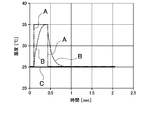
- FIG. 4 shows that the temperature detection method of the present invention can remove the induced noise level very effectively.
- Curves A to C in this figure show the following waveforms.
- Curve A Noise waveform to be input
- Curve B Waveform that has passed through an analog filter
- Curve C Characteristic corrected by the temperature detection method of the present invention
- the detection waveform for detecting the battery temperature of the battery system shown by curve A in this figure includes noise of a rectangular wave.
- the rectangular wave which is noise, has a time width of 300 msec and a temperature change of 25 ° C. to 35 ° C.
- the conventional method using an analog filter has a characteristic indicated by a curve B with a slow change in the detected waveform that has passed through the analog filter.
- the analog filter slows down the steep change, but the peak value cannot be cut, so the change gradually gets closer to the detected temperature waveform and cannot efficiently eliminate all noise.
- the change value of the detected temperature that has passed through the analog filter is specified by the cutoff frequency and attenuation characteristic of the high cut filter.
- the attenuation of noise can be increased by lowering the cutoff frequency and making the attenuation characteristic steep.
- the cut-off frequency is lowered, it becomes impossible to detect a rapid temperature change, and the use of a coil with a large inductance and a capacitor with a large capacitance increases the component cost.
- an analog filter having a large attenuation characteristic increases the number of coils and capacitors used and increases the cost of parts.
- the analog filter since the analog filter has a phase shift from the vicinity of the cut-off frequency, there is a problem that a delay in detection temperature due to the phase shift becomes large. Therefore, even if the analog filter can remove specific noise having a narrow pulse width, it cannot effectively remove various noises.
- the phase characteristic of the analog filter is specified by the frequency characteristic, it is impossible in principle to eliminate the phase shift as the frequency characteristic for removing the noise level. For this reason, the conventional method of reducing the induction noise level with the analog filter cannot theoretically eliminate the time delay for detecting the battery temperature.
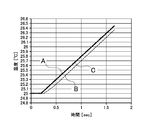
- FIG. 5 is a graph showing the measurement time delay.
- curve A shows the characteristic that the battery temperature changes with time
- curve B shows the characteristic of detecting the temperature by removing noise with an analog filter
- curve C detects the battery temperature by the method of the present invention. The characteristics are shown.
- the method using the analog filter causes a time delay in detecting the temperature, but the method of the present invention does not cause a time delay in detecting the detected temperature.
- the temperature detection method of the present invention has a feature that noise detected can be removed very efficiently as shown by a curve C in FIG. In particular, the noise level can be reduced by cutting the noise peak value.
- the temperature detection method of the present invention when the change value of the detected temperature is larger than the set value, it is determined that the change is caused by noise, and the old change rate ( ⁇ T / ⁇ told) of the previous temperature change is set in advance. This is because the battery temperature is calculated as the actual change rate ( ⁇ T / ⁇ t now) which is one of the set change rates ( ⁇ T / ⁇ t set).
- the temperature detection method of the present invention also realizes the feature that there is no phase shift due to the analog filter, and the change in the battery temperature can be accurately detected with a small time delay.
- an old change rate ( ⁇ T / ⁇ t old) is an average change rate ( ⁇ T / ⁇ t mean) that is an average value of the battery temperature change rate before exceeding the maximum change rate ( ⁇ T / ⁇ t max). ).
- the above temperature detection method is based on the old rate of change ( ⁇ T / ⁇ t ⁇ old), the rate of change before the change rate of battery temperature to be detected [(Traw ⁇ Told) / t] exceeds the maximum rate of change ( ⁇ T / ⁇ t max).
- the average change rate ( ⁇ T / ⁇ t mean), which is an average value of the battery, has a feature that the battery temperature can be more accurately identified from the change rate before the maximum change rate ( ⁇ T / ⁇ t max).
- the temperature detection method of the present invention can set the set change rate ( ⁇ T / ⁇ t set) to a value that is 10% or more and less than 50% of the maximum change rate ( ⁇ T / ⁇ t max).
- the sampling period for detecting the battery temperature can be 100 ⁇ sec or more and 500 msec or less.
- the maximum rate of change ( ⁇ T / ⁇ t max) can be 0.2 ° C./sec or more and 5 ° C./sec or less.
- the maximum rate of change ( ⁇ T / ⁇ t max) set in advance is compared with the rate of increase [(Traw ⁇ Told) / t] of the rising battery temperature.
- Different values can be used for ⁇ T / ⁇ t max) and the maximum rate of change ( ⁇ T / ⁇ t max) on the lower side for comparing the rate of change [(Traw ⁇ Told) / t] of the decreasing battery temperature.
- the above temperature detection method has a feature that noise can be reduced more reliably in both the rising state and the decreasing state of the battery temperature.
- the temperature detection method of the present invention uses the battery system at the maximum load to detect a change in battery temperature, and sets the maximum change rate ( ⁇ T / ⁇ tmax) within a range of the battery temperature change rate at the maximum load ⁇ 100%. can do.
- a battery system 100 in FIG. 1 includes an assembled battery 10 including a plurality of rechargeable batteries 1, a temperature sensor 2 that detects the temperature of the battery 1 that constitutes the assembled battery 10, and input signals such as electrical resistance of the temperature sensor 2.
- a temperature detection circuit 3 for converting to a voltage signal
- an A / D converter 4 for converting an analog signal output from the temperature detection circuit 3 to a digital signal
- an output signal of the A / D converter 4 are calculated, and a temperature terminal 6
- an arithmetic circuit 5 that outputs a battery temperature signal.
- the battery system of FIG. 1 detects a specific battery temperature with one temperature sensor 2, but the battery system is provided with a plurality of temperature sensors to detect all battery temperatures, or a specific battery temperature, for example, the most It is also possible to estimate the temperatures of all the batteries by detecting only the temperature of the battery, such as the battery temperature that becomes the highest temperature, the battery temperature that becomes the lowest temperature, and the average battery temperature.
- the battery system is used in various applications, for example, a power supply mounted on a vehicle to supply electric power to a traveling motor of the vehicle, or a power source for storing natural energy or an uninterruptible power source for supplying power in the event of a power failure. It is important to accurately detect the temperature of the battery 1 in every application. This is because, in order to protect the battery 1, the charge / discharge current of the battery system is controlled by the battery temperature, and the remaining capacity is calculated. In the method of detecting the battery temperature, reducing the noise level is particularly important for accurate temperature detection. This is because noise causes an error in the detected battery temperature.
- the temperature sensor 2 is disposed in a thermal coupling state with the battery 1 to detect the temperature of the battery 1, converts the battery temperature into an electrical resistance, and transmits the electrical resistance to the temperature detection circuit 3. Noise is induced from outside. Furthermore, noise in the power supply circuit is input to all circuits and causes detection errors.
- the temperature detection circuit 3 converts the signal input from the temperature sensor 2 into an analog signal and outputs the analog signal. The temperature detection circuit 3 outputs, for example, a voltage signal proportional to the temperature as an analog signal.
- the temperature sensor 2 receives a temperature signal including noise, and the noise is also input from a power supply circuit.
- the output of the temperature detection circuit 3 is input to the A / D converter 4, and the A / D converter 4 converts the input analog signal into a digital signal and outputs it at a predetermined sampling period. Therefore, the digital signal output from the A / D converter 4 becomes a temperature signal of the battery 1 including noise.
- the arithmetic circuit 5 removes noise from the temperature signal input from the A / D converter 4 and outputs it as an accurate temperature signal from the temperature terminal 6 to the outside.
- the arithmetic circuit 5 detects the temperature of the battery 1 by removing the influence of noise in the following steps.
- the battery system 100 detects the battery temperature at a predetermined sampling period with the A / D converter 4 and outputs the detected battery temperature to the arithmetic circuit 5, which calculates the rate of change of the battery temperature per unit time [(Traw -Told) / t].
- the A / D converter 4 is input from the temperature detection circuit 3 with a sampling period of, for example, 100 ⁇ sec or more and 1 sec or less, preferably 1 msec or more and 500 msec or less, more preferably 2 msec or more and 200 msec or less.
- the analog signal is output to the arithmetic circuit 5 as a digital signal.
- the A / D converter 4 can detect the rapid temperature change of the battery 1 by shortening the sampling period, but the temperature change of the battery 1 is specified by the heat capacity of the battery 1 and the heat generation amount or the heat dissipation amount.
- the sampling period is set to an optimum value in the above-mentioned range in consideration of the temperature change of the battery 1.
- the arithmetic circuit 5 subtracts the previous battery temperature detection value (Told) from the current battery temperature detection value (Traw), and further calculates [(Traw ⁇ Told) / t] to obtain the rate of change in unit time. Is calculated.
- the arithmetic circuit 5 compares the battery temperature change rate [(Traw ⁇ Told) / t] detected in the detection step with a preset maximum change rate ( ⁇ T / ⁇ t max).
- the maximum rate of change ( ⁇ T / ⁇ t max) is specified from the maximum rate of temperature increase in a state where the battery system is charged and discharged with the maximum current.
- the maximum rate of change ( ⁇ T / ⁇ t max) is set to, for example, 100% or more and 200% or less of the maximum temperature increase rate in the use state, preferably 100% or more and 150% or less of the maximum temperature increase rate.
- the maximum rate of change ( ⁇ T / ⁇ t max) can be set within a range of ⁇ 100% of the rate of change in battery temperature at the maximum load by detecting a change in battery temperature while the battery system is used at the maximum load. .
- the maximum rate of change ( ⁇ T / ⁇ t max) can be, for example, 0.2 ° C./sec or more and 5 ° C./sec or less.
- the arithmetic circuit 5 compares the rate of change [(Traw ⁇ Told) / t] of the battery temperature to be detected with the rate of change [(Traw ⁇ Told) / t] compared with the preset maximum rate of change ( ⁇ T / ⁇ t max). t] exceeds the maximum rate of change ( ⁇ T / ⁇ t max), the old rate of change ( ⁇ T / ⁇ t old) of the battery temperature before the maximum rate of change ( ⁇ T / ⁇ t max) or a preset set rate of change
- the battery temperature is calculated as an actual change rate ( ⁇ T / ⁇ t now) which is either ( ⁇ T / ⁇ t set).
- the battery system rises in temperature due to internal heat generation, and cuts off when the current is heated to a high temperature.
- the rate of change in battery temperature ( ⁇ T / ⁇ t) is not necessarily the same when the temperature rises due to heat generation and when the temperature drops due to cooling.
- the rate of change in temperature rise ( ⁇ T / ⁇ t) in a state where charging / discharging is performed at the maximum current is the rate of change in temperature drop in the state where the current is cut off and the cooling is performed while the temperature is raised to the maximum temperature. It becomes larger than ( ⁇ T / ⁇ t).
- the temperature detection method of the present invention can remove noise compared to the maximum rate of change ( ⁇ T / ⁇ t max) in both the state where the battery temperature rises and the state where it falls.
- the maximum rate of change ( ⁇ T / ⁇ t max) in the temperature rising state and the maximum rate of change ( ⁇ T / ⁇ t max) in the state of decreasing temperature may be set to different set values. it can. According to this method, it is possible to more accurately detect the battery temperature when the temperature is lowered. That is, when the temperature is lowered, the rate of change [(Traw ⁇ Told) / t] is compared with a small maximum rate of change ( ⁇ T / ⁇ t max). This is because it can be removed.
- the absolute value of the rate of change ( ⁇ T / ⁇ t) is expressed as the maximum rate of change ( ⁇ T / ⁇ t max). ) Is compared with the absolute value.
- the arithmetic circuit 5 determines that the temperature change of the battery 1 is the actual rate of change ( ⁇ T / ⁇ t now). Calculate the temperature.
- the actual change rate ( ⁇ T / ⁇ t now) is either the old change rate ( ⁇ T / ⁇ t old) or the set change rate ( ⁇ T / ⁇ t set).
- the old change rate ( ⁇ T / ⁇ t old) is calculated from the change rate of the battery temperature before the temperature rise of the battery 1 exceeds the maximum change rate ( ⁇ T / ⁇ t max).
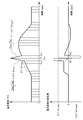
- FIG. 2 shows a state in which the battery temperature detected at a predetermined sampling period changes, that is, a detected temperature signal input from the A / D converter 4 to the arithmetic circuit 5 and a rate of change in unit time ( ⁇ T / ⁇ t).
- the detected temperature signal of FIG. 2 increases rapidly due to the influence of the induction noise at the timing of Tn and shows a peak value. Therefore, the change rate [(Traw ⁇ Told) / t] of the detected temperature signal exceeds the maximum change rate ( ⁇ T / ⁇ t max) at the timing of Tn.
- the old change rate ( ⁇ T / ⁇ t old) is calculated from the change rate of the battery temperature before the temperature rise of the battery 1 exceeds the maximum change rate ( ⁇ T / ⁇ t max).
- the arithmetic circuit 5 calculates the old change rate ( ⁇ T / ⁇ t old) at a timing before Tn from the battery temperature at time Tn-1 and the battery temperature at time Tn-2. That is, the arithmetic circuit 5 [(Battery temperature at time Tn-1)-(Battery temperature at time Tn-2)] / hour.
- the arithmetic circuit 5 calculates an average change rate ( ⁇ T / ⁇ t mean), which is an average value of the change rates of the battery temperature at a plurality of timings, as an old change rate ( ⁇ T / ⁇ t old). You can also.
- the method of calculating the old change rate ( ⁇ T / ⁇ t old) from the average value specifies the number of times of calculating the average value in consideration of the sampling period of the A / D converter 4 and the gradient at which the battery temperature changes.
- the number of times of calculating the average value is preferably 3 times or more and 100 times or less. For example, the detected temperature is 10 times before the sampling period is 100 msec and the maximum rate of change ( ⁇ T / ⁇ t max) is exceeded.
- the average rate of change ( ⁇ T / ⁇ t mean) is calculated from the average value, the average value one second before exceeding the maximum rate of change ( ⁇ T / ⁇ t max) can be calculated as the old rate of change ( ⁇ T / ⁇ t old).
- the set change rate ( ⁇ T / ⁇ t set) is smaller than the maximum change rate ( ⁇ T / ⁇ tmax), and is an average value in a state where the temperature of the battery 1 changes, for example, 10% or more of the maximum change rate ( ⁇ T / ⁇ t max). And set to 50% or less.
- the arithmetic circuit 5 determines that the change rate of the detected battery temperature [(Traw ⁇ Told) / t] is smaller than the maximum change rate ( ⁇ T / ⁇ t max), and that the detected change rate is not affected by noise.
- the battery temperature is calculated with [(Traw ⁇ Told) / t] as the temperature change of the battery 1.
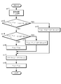
- the arithmetic circuit 5 detects the battery temperature accurately by preventing the influence of noise in the following flowchart shown in FIG.
- Step of n 1]
- the A / D converter 4 inputs the input analog signal to the arithmetic circuit 5 as a digital signal corresponding to the temperature at a predetermined sampling period.
- the arithmetic circuit 5 detects the current battery temperature (Traw) from the signal input from the A / D converter 4.
- Step n 3] If the arithmetic circuit 5 determines that the rate of change [(Traw ⁇ Told) / t] of the battery temperature that rises in temperature is greater than the maximum rate of change ( ⁇ T / ⁇ t max), in this step, the previous battery temperature (Told) Is added with the temperature change calculated from the actual change rate ( ⁇ T / ⁇ t now) to calculate the current temperature (Tnow) of the battery 1.
- the actual change rate ( ⁇ T / ⁇ t now) is, for example, an average change rate ( ⁇ T / ⁇ t mean) that is an average value of 100 change rates before exceeding the maximum change rate ( ⁇ T / ⁇ t max). ⁇ T / ⁇ t old).
- Step n 4] This step determines whether the rate of change of the decreasing battery temperature exceeds the maximum rate of change.
- the rate of change [(Traw ⁇ Told) / t] becomes a negative value, and the absolute value of the negative value indicates the absolute value of the maximum rate of change ( ⁇ T / ⁇ t max). Over. Accordingly, when the absolute value of the rate of change [(Traw ⁇ Told) / t] of the battery temperature that exceeds the maximum rate of change ( ⁇ T / ⁇ t max) exceeds [(Traw ⁇ Told) / t] ⁇ ( ⁇ T / ⁇ t max).
- the arithmetic circuit 5 determines that the change rate has the maximum change rate. Judge that it exceeded.
- Step n 5] Decreasing battery temperature change rate [(Traw ⁇ Told) / t] is smaller than ⁇ ( ⁇ T / ⁇ t max), that is, an absolute value of decreasing battery temperature change rate [(Traw ⁇ Told) / t] is If it is determined that the rate of change is greater than the maximum rate of change ( ⁇ T / ⁇ t max), the temperature change calculated from the actual rate of change ( ⁇ T / ⁇ t now) is subtracted from the previous battery temperature (Told) in this step. The current temperature (Tnow) of 1 is calculated.
- the actual change rate ( ⁇ T / ⁇ t now) is preferably the old average change rate ( ⁇ T / ⁇ t mean), which is the average value of the change rate before the maximum change rate ( ⁇ T / ⁇ t max). It is assumed that the rate of change ( ⁇ T / ⁇ t old).
- Step n 6] In a state where both the rate of change of the rising battery temperature and the rate of change of the decreasing battery temperature do not exceed the maximum rate of change, in this step, the arithmetic circuit 5 detects the current temperature (Tnow) of the battery 1 as detected current. Battery temperature (Traw).
- Step n 7]
- the arithmetic circuit 5 calculates the actual change rate ( ⁇ T / ⁇ t now).
- the actual change rate ( ⁇ T / ⁇ t now) is calculated as the old change rate ( ⁇ T / ⁇ t old).
- Old change rate ( ⁇ T / ⁇ t old) is [Current temperature (Tnow) -Previous detection temperature (Told)] / t.
- the arithmetic circuit 5 calculates an average change rate ( ⁇ T / ⁇ t mean), which is an average value of the change rates [(Tnow ⁇ Told) / t] for a plurality of times, as an old change rate ( ⁇ T / ⁇ t old).
- the number of times of calculating the average value is specified in consideration of the sampling period, and can be, for example, 3 times or more and 100 times or less.
- the arithmetic circuit 5 calculates an average change rate ( ⁇ T / ⁇ t mean) from an average value of 10 change rates with a sampling period of 100 msec, and the old average is the calculated average change rate ( ⁇ T / ⁇ t mean)
- the rate of change ( ⁇ T / ⁇ t old) be the actual rate of change ( ⁇ T / ⁇ t now).
- the present invention is particularly effectively used in a battery system that prevents the influence of noise and accurately detects the battery temperature, for example, a battery system used in a power supply device for a vehicle having a large amount of external noise.
Landscapes
- Physics & Mathematics (AREA)
- Engineering & Computer Science (AREA)
- Manufacturing & Machinery (AREA)
- Chemical & Material Sciences (AREA)
- Chemical Kinetics & Catalysis (AREA)
- Electrochemistry (AREA)
- General Chemical & Material Sciences (AREA)
- General Physics & Mathematics (AREA)
- Nonlinear Science (AREA)
- Secondary Cells (AREA)
- Charge And Discharge Circuits For Batteries Or The Like (AREA)
Abstract
安価な回路構成で誘導ノイズレベルを安定して低減し、検出の時間遅れを少なくして電池温度を正確に検出するために、電池温度を所定のサンプリング周期で検出して電池温度の単位時間の変化率[(Traw-Told)/t]を検出する検出工程と、検出された電池温度の変化率[(Traw-Told)/t]が最大変化率(ΔT/Δt max)を越えると、電池温度の旧変化率(ΔT/Δt old)又は設定変化率(ΔT/Δt set)の何れかの現実変化率(ΔT/Δt now)として電池温度を演算し、電池温度の変化率[(Traw-Told)/t]が最大変化率(ΔT/Δt max)よりも小さい状態では検出された変化率[(Traw-Told)/t]を電池1の温度変化として電池温度を演算する。
Description
本発明は、バッテリシステムを構成する電池の温度を検出する方法に関し、とくにノイズによる誤検出を防止して電池の温度を検出する方法に関する。
電源装置に使用されるバッテリシステムは、電動車両を走行させる電源として使用され、あるいは自然エネルギーを蓄電して負荷に電力を供給する電源として使用され、あるいはまた、停電時に負荷に電力を供給する電源などに使用されるが、これ等のバッテリシステムは、使用される充放電の電流や温度などの外的環境によって電池の温度が変化する。このバッテリシステムは、電池の温度を監視しながら充放電をコントロールすることが、安全性を確保する上で重要である。電池温度が正常に使用可能な範囲から外れる状態では、安全性が確保されず、また電池の電気特性の劣化による寿命が低下し、さらに発煙や発火にいたる可能性もあるからである。また、バッテリシステムの安全監視においても、電池の温度が異常な状態となったことの検出は、即時の動作、たとえば、出力側に接続しているリレーをオープンに切り換える等の安全性を確保する動作を取る必要もあり、極めて重要である。これらのことから、バッテリシステムは、電池の温度を速やかに、しかも正確に検出することが求められる。
電池の温度を検出するために、温度センサで電池温度を検出するバッテリシステムは開発されている。(特許文献1参照)
電池温度は、サーミスター等の温度センサを電池の表面に熱結合状態に固定し、温度センサと検出回路とをリード線で接続し、検出回路でもってサーミスターの電気抵抗から電池温度を検出している。この回路構成のバッテリシステムは、温度センサを温度検出に最適な位置に配置して、回路基板に電子部品を実装して実現される。検出回路は、回路基板の配置に最適な位置に配置されるので、温度センサと回路基板とは離れて配置され、両者をリード線で接続する必要がある。温度センサと回路基板がリード線で接続されるので、リード線にはノイズが誘導され、誘導されるノイズによって検出温度に誤差が発生する。このノイズは、バッテリシステムの内部から誘導され、さらにバッテリシステムが電力を供給しているシステムからも誘導されるので、リード線に誘導されるノイズを皆無にはできない。リード線を完全にシールドすることは誘導ノイズを低減することに有効ではあるが、この方法によっては誘導ノイズを完全には除去できない。また、温度センサにもノイズが誘導されるので、仮に完全にリード線をシールドできるとしても、温度センサから検出回路に入力される信号には誘導されたノイズが含まれる。
リード線に誘導されるノイズは、検出回路の入力側に、コンデンサーやコイルで構成される、アナログフィルタであるハイカットフィルタのノイズフィルタを設けて低減できる。ノイズの周波数成分が温度変化よりも高いからである。ただ、アナログフィルタは、ノイズ成分を有効に除去するほど、すなわち、ノイズ成分をより効果的に減衰させる理想的な周波数特性を実現するほど、部品コストが高くなる。さらに、検出回路の入力側にアナログフィルタを設けると、位相がずれて電池温度の検出温度が遅れる弊害がある。とくに、減衰特性を急峻にするほど位相のずれが大きく、検出時間の遅れが大きくなる欠点がある。
本発明は、以上の欠点を解決することを目的に開発されたものである。本発明の重要な目的は、多数の部品を使用することなく安価な回路構成で誘導ノイズレベルを安定して低減でき、しかも検出時間遅れを極限して電池温度を正確に検出できるバッテリシステムの温度検出方法を提供することにある。
本発明の温度検出方法は、検出工程と温度特定工程とで電池の温度を検出する。検出工程は、バッテリシステムの電池温度を所定のサンプリング周期で検出して電池温度の単位時間の変化率[(Traw-Told)/t]を検出する。温度特定工程は、検出工程で検出された電池温度の変化率[(Traw-Told)/t]を、あらかじめ設定している最大変化率(ΔT/Δt max)に比較して、変化率[(Traw-Told)/t]が最大変化率(ΔT/Δt max)を越えると、最大変化率(ΔT/Δt max)を越える以前の電池温度の旧変化率(ΔT/Δt old)又はあらかじめ設定している設定変化率(ΔT/Δt set)の何れかである現実変化率(ΔT/Δt now)として電池温度を演算し、検出される電池温度の変化率[(Traw-Told)/t]が最大変化率(ΔT/Δt max)よりも小さい状態では検出された変化率[(Traw-Told)/t]を電池の温度変化として電池温度を演算する。
ただし、Trawは現在の電池温度の検出値、ToldはTrawを検出する以前の電池温度の検出値である。
ただし、Trawは現在の電池温度の検出値、ToldはTrawを検出する以前の電池温度の検出値である。
以上のバッテリシステムの温度検出方法は、アナログフィルタを構成するコイルやコンデンサー等の多数の電子部品を使用することなく、安価な回路構成としながら確実に誘導ノイズレベルを低減でき、また、電池温度の検出時間遅れを小さくできる特徴を実現する。それは、以上の温度検出方法が、アナログフィルタでノイズを減衰するのではなく、検出する電池温度の変化率[(Traw-Told)/t]を、あらかじめ設定している最大変化率(ΔT/Δt max)に比較して、変化率[(Traw-Told)/t]が最大変化率(ΔT/Δt max)を越えると、電池温度の旧変化率(ΔT/Δt old)や設定変化率(ΔT/Δt set)で変化したとして、電池の温度を特定するからである。
電池の温度が上昇する変化率は、内部の発熱量とそれ自体の熱容量で特定される。発熱量が大きいと温度上昇の勾配は大きく、熱容量が大きいと温度上昇の勾配は緩やかになる。電池の発熱量は流れる電流から特定され、電池の最大電流は接続される負荷によって特定され、電池の熱容量は、電池の重量と比熱で特定される。したがって、電池温度が上昇する変化率の最大値は、バッテリシステムを接続する負荷と電池の重量などで特定され、変化率が最大値を超えることはない。これに対して、ノイズは極めて広い周波数成分を含むことから、ノイズの変化率は、電池温度の変化率を越えることがある。本発明は、検出する電池温度の変化率を最大変化率(ΔT/Δt max)に比較して、最大変化率(ΔT/Δt max)を越える状態ではノイズによる変化と判定して、現実変化率(ΔT/Δt now)から電池温度を特定する。したがって、電池温度の検出ラインに、最大変化率(ΔT/Δt max)を越えるノイズが誘導される状態においは、ノイズの影響を受けることなく電池温度を正確に検出できる特徴がある。
図4は、本発明の温度検出方法が、誘導ノイズレベルを極めて効果的に除去できことを示している。
この図の曲線A~Cは以下の波形を示している。
曲線A…入力されるノイズ波形
曲線B…アナログフィルタを通過した波形
曲線C…本発明の温度検出方法で温度補正した特性
この図の曲線A~Cは以下の波形を示している。
曲線A…入力されるノイズ波形
曲線B…アナログフィルタを通過した波形
曲線C…本発明の温度検出方法で温度補正した特性
この図の曲線Aで示す、バッテリシステムの電池温度を検出する検出波形は矩形波のノイズを含んでいる。ノイズである矩形波は、時間幅を300msec、温度変化を25℃から35℃としている。
この図で示すように、従来のアナログフィルタによる方式は、アナログフィルタを通過した検出波形の変化を緩慢にして曲線Bで示す特性となる。アナログフィルタは急峻な変化を緩慢にするが、ピーク値をカットできないので、変化は次第に検出温度波形に近づいて大きくなって全てのノイズを効率よくできない。アナログフィルタを通過した検出温度の変化値は、ハイカットフィルタのカットオフ周波数と減衰特性で特定される。カットオフ周波数を低くして減衰特性を急峻な特性として、ノイズの減衰を大きくできる。しかしながら、カットオフ周波数を低くすると、急激な温度変化を検出できなくなると共に、大きなインダクタンスのコイルと大きな静電容量のコンデンサーを使用するので部品コストが高くなる。また、減衰特性の大きなアナログフィルタは、コイルやコンデンサーの使用個数が多くなって部品コストが増加する。また、アナログフィルタは、カットオフ周波数の付近から位相がずれるので、位相のずれによる検出温度の遅れが大きくなる弊害もある。したがって、アナログフィルタは、パルス幅の狭い特定のノイズを除去できても、種々のノイズを効果的に除去できない。以上のようにアナログフィルタは、周波数特性によって位相特性が特定されるので、ノイズレベルを除去する周波数特性として、位相のずれを皆無にすることは原理的にできない。このため、アナログフィルタで誘導ノイズレベルを低減する従来の方法では、電池温度を検出する時間遅れを原理的に解消できない。
図5は、測定の時間遅れを示すグラフである。この図において曲線Aは、時間と共に電池温度が変化する特性を示し、曲線Bはアナログフィルタでノイズを除去して温度を検出する特性を示し、曲線Cは本発明の方法で電池温度を検出する特性を示している。この図に示すように、アナログフィルタを使用する方法は、温度の検出に時間遅れが発生するが、本発明の方法は、検出温度を検出する時間遅れが発生しない。
本発明の温度検出方法は、図4の曲線Cで示すように、検出されるノイズを極めて効率よく除去できる特徴がある。とくに、ノイズのピーク値をカットしてノイズレベルを低減できる特徴がある。それは、本発明の温度検出方法が、検出温度の変化値が設定値よりも大きな状態では、ノイズによる変化と判定して、以前の温度変化の旧変化率(ΔT/Δtold)やあらかじめ設定している設定変化率(ΔT/Δt set)の何れかである現実変化率(ΔT/Δt now)として電池温度を演算するからである。また、本発明の温度検出方法は、アナログフィルタによる位相のずれがなく、電池温度の変化を、時間遅れを小さくして、正確に検出できる特徴も実現する。
本発明の温度検出方法は、旧変化率(ΔT/Δt old)を、最大変化率(ΔT/Δt max)を越える以前の電池温度の変化率の平均値である平均変化率(ΔT/Δt mean)とすることができる。
以上の温度検出方法は、旧変化率(ΔT/Δt old)を、検出する電池温度の変化率[(Traw-Told)/t]が最大変化率(ΔT/Δt max)を越える以前の変化率の平均値である平均変化率(ΔT/Δt mean)とするので、最大変化率(ΔT/Δt max)を越える以前の変化率から電池温度をより正確に特定できる特徴がある。
本発明の温度検出方法は、設定変化率(ΔT/Δt set)を、最大変化率(ΔT/Δt max)の10%以上であって50%未満の値に設定することができる。
本発明の温度検出方法は、電池温度を検出するサンプリング周期を、100μsec以上であって500msec以下とすることができる。
本発明の温度検出方法は、最大変化率(ΔT/Δt max)を0.2℃/sec以上であって5℃/sec以下とすることができる。
本発明の温度検出方法は、あらかじめ設定している最大変化率(ΔT/Δt max)が、上昇する電池温度の変化率[(Traw-Told)/t]を比較する上昇側の最大変化率(ΔT/Δt max)と、低下する電池温度の変化率[(Traw-Told)/t]を比較する低下側の最大変化率(ΔT/Δt max)とで異なる値とすることができる。
以上の温度検出方法は、電池温度の上昇状態と、低下状態の両方でより確実にノイズを低減できる特徴がある。
本発明の温度検出方法は、バッテリシステムを最大負荷で使用して電池温度の変化を検出し、最大変化率(ΔT/Δtmax)を、最大負荷における電池温度の変化率±100%の範囲に設定することができる。
以下、本発明の実施例を図面に基づいて説明する。ただし、以下に示す実施例は、本発明の技術思想を具体化するための温度検出方法を例示するものであって、本発明は温度検出方法を以下のものに特定しない。さらに、この明細書は、特許請求の範囲を理解しやすいように、実施例に示される部材に対応する番号を、「特許請求の範囲」および「課題を解決するための手段の欄」に示される部材に付記している。ただ、特許請求の範囲に示される部材を、実施例の部材に特定するものでは決してない。
以下、図面に基づいて、さらに具体的な実施例を詳述する。
図1のバッテリシステム100は、複数の充電できる電池1からなる組電池10と、組電池10を構成する電池1の温度を検出する温度センサ2と、温度センサ2の電気抵抗などの入力信号を電圧信号に変換する温度検出回路3と、この温度検出回路3から出力されるアナログ信号をデジタル信号に変換するA/Dコンバータ4と、A/Dコンバータ4の出力信号を演算して温度端子6から電池温度の信号として出力する演算回路5とを備える。
図1のバッテリシステム100は、複数の充電できる電池1からなる組電池10と、組電池10を構成する電池1の温度を検出する温度センサ2と、温度センサ2の電気抵抗などの入力信号を電圧信号に変換する温度検出回路3と、この温度検出回路3から出力されるアナログ信号をデジタル信号に変換するA/Dコンバータ4と、A/Dコンバータ4の出力信号を演算して温度端子6から電池温度の信号として出力する演算回路5とを備える。
図1のバッテリシステムは、ひとつの温度センサ2で特定の電池温度を検出するが、バッテリシステムは、複数の温度センサを設けて全ての電池温度を検出し、あるいは特定の電池温度、たとえば、最も高温になる電池温度や最も低温になる電池温度、さらに平均的な電池温度などの電池の温度のみを検出して、全ての電池の温度を推測することもできる。
バッテリシステムは、種々の用途、たとえば、車両に搭載されて車両の走行モータに電力を供給し、あるいは自然エネルギーを蓄電する電源や停電時に電力を供給する無停電電源の電源に使用されるが、あらゆる用途において電池1の温度を正確に検出すること大切である。それは、電池1を保護するために、電池温度でバッテリシステムの充放電の電流をコントロールし、また残容量を演算するからである。電池温度を検出する方法において、ノイズレベルを低減することは、正確な温度検出においてとくに大切である。ノイズが、検出する電池温度の誤差の原因となるからである。
温度検出において、ノイズは、種々の要因で検出信号に誘導される。たとえば、温度センサ2は、電池1に熱結合状態に配置されて電池1の温度を検出し、電池温度を電気抵抗に変換して温度検出回路3に伝送するが、温度センサ2のリード線7に外部からノイズが誘導される。さらに、電源回路のノイズは全ての回路に入力されて、検出誤差の原因となる。温度検出回路3は、温度センサ2から入力される信号をアナログ信号に変換して出力する。この温度検出回路3は、たとえば温度に比例する電圧信号をアナログ信号として出力するが、温度センサ2からはノイズを含む温度信号が入力され、またノイズは電源回路からも入力される。
温度検出回路3の出力は、A/Dコンバータ4に入力され、A/Dコンバータ4は、所定のサンプリング周期で、入力されるアナログ信号をデジタル信号に変換して出力する。したがって、A/Dコンバータ4から出力されるデジタル信号は、ノイズを含む電池1の温度信号となる。演算回路5は、A/Dコンバータ4から入力される温度信号からノイズを除去して、正確な温度信号として温度端子6から外部に出力する。
演算回路5は、以下の工程で、ノイズの影響を除いて電池1の温度を検出する。
[検出工程]
この工程で、バッテリシステム100は、A/Dコンバータ4でもって、電池温度を所定のサンプリング周期で検出して演算回路5に出力し、演算回路5は電池温度の単位時間の変化率[(Traw-Told)/t]を演算する。A/Dコンバータ4は、たとえば、100μsec以上であって1sec以下、好ましくは1msec以上であって500msec以下、さらに好ましくは2msec以上であって200msec以下のサンプリング周期で、温度検出回路3から入力されるアナログ信号をデジタル信号として演算回路5に出力する。A/Dコンバータ4は、サンプリング周期を短くして、電池1の速やかな温度変化を検出できるが、電池1の温度変化は、電池1の熱容量と、発熱量又は放熱量で特定されるので、サンプリング周期は電池1の温度変化を考慮して、前述の範囲で最適値に設定される。
演算回路5は、現在の電池温度の検出値(Traw)から前回の電池温度の検出値(Told)を減算し、さらに[(Traw-Told)/t]を演算して、単位時間の変化率を演算する。
[温度特定工程]
この工程において、演算回路5は、検出工程で検出された電池温度の変化率[(Traw-Told)/t]を、あらかじめ設定している最大変化率(ΔT/Δt max)に比較する。最大変化率(ΔT/Δt max)は、バッテリシステムを最大電流で充放電する状態における、最大温度上昇率から特定する。最大変化率(ΔT/Δt max)は、たとえば、使用状態における最大温度上昇率の100%以上であって200%以下、好ましくは最大温度上昇率の100%以上であって150%以下に設定される。
この工程において、演算回路5は、検出工程で検出された電池温度の変化率[(Traw-Told)/t]を、あらかじめ設定している最大変化率(ΔT/Δt max)に比較する。最大変化率(ΔT/Δt max)は、バッテリシステムを最大電流で充放電する状態における、最大温度上昇率から特定する。最大変化率(ΔT/Δt max)は、たとえば、使用状態における最大温度上昇率の100%以上であって200%以下、好ましくは最大温度上昇率の100%以上であって150%以下に設定される。
また、最大変化率(ΔT/Δt max)は、バッテリシステムを最大負荷で使用する状態で電池温度の変化を検出し、最大負荷における電池温度の変化率±100%の範囲に設定することもできる。最大変化率(ΔT/Δt max)は、たとえば、0.2℃/sec以上であって5℃/sec以下とすることができる。
演算回路5は、検出する電池温度の変化率[(Traw-Told)/t]をあらかじめ設定している最大変化率(ΔT/Δt max)に比較して、変化率[(Traw-Told)/t]が最大変化率(ΔT/Δt max)を越えると、最大変化率(ΔT/Δt max)を越える以前の電池温度の旧変化率(ΔT/Δt old)又はあらかじめ設定している設定変化率(ΔT/Δt set)の何れかである現実変化率(ΔT/Δt now)として電池温度を演算する。
バッテリシステムは、内部発熱して温度上昇し、高温に加熱された状態で電流を遮断して低下する。電池温度の変化率(ΔT/Δt)は、発熱して温度が上昇する時と、冷却して温度が低下する時では必ずしも同一とならない。通常の使用状態では、最大電流で充放電される状態における温度上昇の変化率(ΔT/Δt)は、最高温度に上昇した状態で電流を遮断して、冷却する状態での温度低下の変化率(ΔT/Δt)よりも大きくなる。したがって、最大変化率(ΔT/Δt max)を、バッテリシステムを最大電流で充放電して温度上昇する変化率(ΔT/Δt)以上に設定すると、バッテリシステムが温度上昇する状態と、温度が低下する状態で、設定する最大変化率(ΔT/Δt max)を越えることがない。このため、本発明の温度検出方法は、電池温度が上昇する状態と、低下する状態の両方で最大変化率(ΔT/Δt max)に比較して、ノイズを除去できる。ただ、本発明の温度検出方法は、温度上昇する状態における最大変化率(ΔT/Δt max)と、温度が低下する状態との最大変化率(ΔT/Δt max)を異なる設定値とすることもできる。この方法によると、温度が低下する状態における電池温度をより正確に検出できる。それは、温度が低下する状態では、小さく設定している最大変化率(ΔT/Δt max)に変化率[(Traw-Told)/t]を比較するので、より小さいレベルのノイズをノイズと判定して除去できるからである。なお、温度が低下する状態における変化率(ΔT/Δt)は、実際には負の値になるが、ここでは、変化率(ΔT/Δt)の絶対値を、最大変化率(ΔT/Δt max)の絶対値と比較する状態を示している。
演算回路5は、変化率[(Traw-Told)/t]が最大変化率(ΔT/Δt max)を越えるときは、電池1の温度変化が現実変化率(ΔT/Δt now)であるとして電池温度を演算する。現実変化率(ΔT/Δt now)は、旧変化率(ΔT/Δt old)、又は設定変化率(ΔT/Δt set)のいずれかとする。旧変化率(ΔT/Δt old)は、電池1の温度上昇が最大変化率(ΔT/Δt max)を越える以前の電池温度の変化率から演算する。
図2は、所定のサンプリング周期で検出される電池温度が変化する状態、すなわちA/Dコンバータ4から演算回路5に入力される検出温度信号と、この温度変化における単位時間の変化率(ΔT/Δt)を示している。図2の検出温度信号は、Tnのタイミングにおいて、誘導ノイズの影響で急激に大きくなってピーク値を示している。したがって、検出温度信号の変化率[(Traw-Told)/t]は、Tnのタイミングで、最大変化率(ΔT/Δt max)を越える状態となる。旧変化率(ΔT/Δt old)は、電池1の温度上昇が最大変化率(ΔT/Δt max)を越える以前の電池温度の変化率から演算される。したがって、演算回路5は、Tnより前のタイミングにおける旧変化率(ΔT/Δt old)を、時間Tn-1における電池温度と時間Tn-2における電池温度から演算する。すなわち、演算回路5は、
[(時間Tn-1における電池温度)-(時間Tn-2における電池温度)]/時間で演算する。
[(時間Tn-1における電池温度)-(時間Tn-2における電池温度)]/時間で演算する。
さらに、図2に示すように、演算回路5は、複数のタイミングにおける電池温度の変化率の平均値である平均変化率(ΔT/Δt mean)を旧変化率(ΔT/Δt old)として演算することもできる。平均値から旧変化率(ΔT/Δt old)を演算する方法は、A/Dコンバータ4のサンプリング周期と電池温度が変化する勾配を考慮して、平均値を演算する回数を特定する。平均値を演算する回数は、好ましくは3回以上であって100回以下とすることができ、たとえば、サンプリング周期を100msec、最大変化率(ΔT/Δt max)を越える前の10回の検出温度の平均値から平均変化率(ΔT/Δt mean)を演算すると、最大変化率(ΔT/Δt max)を越える1秒前の平均値を旧変化率(ΔT/Δt old)として演算できる。
設定変化率(ΔT/Δt set)は、最大変化率(ΔT/Δtmax)よりも小さく、電池1の温度が変化する状態における平均値、たとえば、最大変化率(ΔT/Δt max)の10%以上であって50%以下に設定される。
演算回路5は、検出される電池温度の変化率[(Traw-Told)/t]が最大変化率(ΔT/Δt max)よりも小さい状態では、ノイズの影響がないとして、検出された変化率[(Traw-Told)/t]を電池1の温度変化として電池温度を演算する。
演算回路5は、図3に示す以下のフローチャートで、ノイズの影響を防止して電池温度を正確に検出する。
(電池温度の検出工程)
[n=1のステップ]
このステップにおいて、A/Dコンバータ4は入力されるアナログ信号を、所定のサンプリング周期で、温度に対応するデジタル信号として演算回路5に入力する。演算回路5は、A/Dコンバータ4から入力される信号から、現在の電池温度(Traw)を検出する。
[n=1のステップ]
このステップにおいて、A/Dコンバータ4は入力されるアナログ信号を、所定のサンプリング周期で、温度に対応するデジタル信号として演算回路5に入力する。演算回路5は、A/Dコンバータ4から入力される信号から、現在の電池温度(Traw)を検出する。
(温度特定工程)
[n=2のステップ]
このステップは、上昇する電池温度の変化率が最大変化率を越えるかどうかを判定する。このことを実現するために、演算回路5は、現在の電池温度(Traw)から前回に検出した電池温度(Told)を減算して、温度差から単位時間における電池温度の変化率[(Traw-Told)/t]を演算し、さらに、変化率[(Traw-Told)/t]が最大変化率(ΔT/Δt max)よりも大きいかどうかを判定する。
[n=2のステップ]
このステップは、上昇する電池温度の変化率が最大変化率を越えるかどうかを判定する。このことを実現するために、演算回路5は、現在の電池温度(Traw)から前回に検出した電池温度(Told)を減算して、温度差から単位時間における電池温度の変化率[(Traw-Told)/t]を演算し、さらに、変化率[(Traw-Told)/t]が最大変化率(ΔT/Δt max)よりも大きいかどうかを判定する。
[n=3のステップ]
演算回路5は、温度上昇する電池温度の変化率[(Traw-Told)/t]が最大変化率(ΔT/Δt max)よりも大きいと判定すると、このステップにおいて、前回の電池温度(Told)に現実変化率(ΔT/Δt now)から演算される温度変化を加算して、電池1の現在温度(Tnow)を演算する。
現実変化率(ΔT/Δt now)は、たとえば、最大変化率(ΔT/Δt max)を越える以前の100回の変化率の平均値である平均変化率(ΔT/Δt mean)を旧変化率(ΔT/Δt old)とする。
演算回路5は、温度上昇する電池温度の変化率[(Traw-Told)/t]が最大変化率(ΔT/Δt max)よりも大きいと判定すると、このステップにおいて、前回の電池温度(Told)に現実変化率(ΔT/Δt now)から演算される温度変化を加算して、電池1の現在温度(Tnow)を演算する。
現実変化率(ΔT/Δt now)は、たとえば、最大変化率(ΔT/Δt max)を越える以前の100回の変化率の平均値である平均変化率(ΔT/Δt mean)を旧変化率(ΔT/Δt old)とする。
[n=4のステップ]
このステップは、低下する電池温度の変化率が最大変化率を越えるかどうかを判定する。
低下する電池温度の変化率が最大変化率を越えると、変化率[(Traw-Told)/t]はマイナス値となり、マイナス値の絶対値が最大変化率(ΔT/Δt max)の絶対値を越える。したがって、低下する電池温度の変化率[(Traw-Told)/t]の絶対値が、最大変化率(ΔT/Δt max)を越えると、 [(Traw-Told)/t]<-(ΔT/Δt max)となる。
したがって、このステップにおいて、演算回路5は、電池温度の変化率[(Traw-Told)/t]がマイナスの最大変化率(-ΔT/Δt max)よりも小さいと、変化率が最大変化率を越えたと判定する。
[n=5のステップ]
低下する電池温度の変化率[(Traw-Told)/t]が-(ΔT/Δt max)よりも小さい、すなわち、低下する電池温度の変化率[(Traw-Told)/t]の絶対値が、最大変化率(ΔT/Δt max)よりも大きいと判定すると、このステップにおいて、前回の電池温度(Told)から現実変化率(ΔT/Δt now)から演算される温度変化を減算して、電池1の現在温度(Tnow)を演算する。
このステップにおいても、現実変化率(ΔT/Δt now)は、好ましくは、最大変化率(ΔT/Δt max)を越える以前の変化率の平均値である平均変化率(ΔT/Δt mean)を旧変化率(ΔT/Δt old)とする。
[n=6のステップ]
上昇する電池温度の変化率と低下する電池温度の変化率の両方が最大変化率を越えない状態では、このステップにおいて、演算回路5は、電池1の現在温度(Tnow)を、検出した現在の電池温度(Traw)とする。
上昇する電池温度の変化率と低下する電池温度の変化率の両方が最大変化率を越えない状態では、このステップにおいて、演算回路5は、電池1の現在温度(Tnow)を、検出した現在の電池温度(Traw)とする。
[n=7のステップ]
このステップにおいて、演算回路5は現実変化率(ΔT/Δt now)を演算する。このステップでは、現実変化率(ΔT/Δt now)は、旧変化率(ΔT/Δt old)として演算される。
旧変化率(ΔT/Δt old)は、
[現在温度(Tnow)-前回の検出温度(Told)]/tで演算される。
演算回路5は、複数回の変化率[(Tnow-Told)/t]の平均値である平均変化率(ΔT/Δt mean)を旧変化率(ΔT/Δt old)として演算する。平均値を演算する回数は、サンプリング周期を考慮して特定されるが、たとえば、3回以上であって100回以下にできる。演算回路5は、たとえば、サンプリング周期を100msecとして、10回の変化率の平均値から平均変化率(ΔT/Δt mean)を演算し、演算された平均変化率(ΔT/Δt mean)である旧変化率(ΔT/Δt old)を現実変化率(ΔT/Δt now)とする。
[n=8のステップ]
このステップで、現在温度(Tnow)を、n=2のステップで使用する前回に検出した電池温度(Told)とし、その後、n=1~8のステップをループして、変化する電池1の現在温度(Tnow)を検出する。
このステップで、現在温度(Tnow)を、n=2のステップで使用する前回に検出した電池温度(Told)とし、その後、n=1~8のステップをループして、変化する電池1の現在温度(Tnow)を検出する。
本発明は、雑音の影響を阻止して正確に電池温度を検出するバッテリシステム、たとえば、外来ノイズの大きい車両用の電源装置などに使用されるバッテリシステムにおいて特に有効に使用される。
100…バッテリシステム、 1…電池、 2…温度センサ、 3…温度検出回路、 4…A/Dコンバータ、 5…演算回路、 6…温度端子、 7…リード線、 10…組電池
Claims (7)
- バッテリシステムの電池温度を所定のサンプリング周期で検出して電池温度の単位時間の変化率[(Traw-Told)/t]を検出する検出工程と、
前記検出工程で検出された電池温度の変化率[(Traw-Told)/t]を、あらかじめ設定している最大変化率(ΔT/Δt max)に比較して、前記変化率[(Traw-Told)/t]が最大変化率(ΔT/Δt max)を越えると、最大変化率(ΔT/Δt max)を越える以前の電池温度の旧変化率(ΔT/Δt old)又はあらかじめ設定している設定変化率(ΔT/Δt set)の何れかである現実変化率(ΔT/Δt now)として電池温度を演算し、
検出される電池温度の変化率[(Traw-Told)/t]が最大変化率(ΔT/Δt max)よりも小さい状態では検出された変化率[(Traw-Told)/t]を電池の温度変化として電池温度を演算する温度特定工程とからなるバッテリシステムの温度検出方法。 - 請求項1に記載されるバッテリシステムの温度検出方法であって、
前記旧変化率(ΔT/Δt old)を、最大変化率(ΔT/Δtmax)を越える以前の電池温度の変化率の平均値である平均変化率(ΔT/Δt mean)とすることを特徴とするバッテリシステムの温度検出方法。 - 請求項1に記載されるバッテリシステムの温度検出方法であって、
前記設定変化率(ΔT/Δt set)を、前記最大変化率(ΔT/Δt max)の10%以上であって50%未満の値に設定してなることを特徴とするバッテリシステムの温度検出方法。 - 請求項1ないし3のいずれかに記載されるバッテリシステムの温度検出方法であって、
電池温度を検出するサンプリング周期を、100μsec以上であって500msec以下とするバッテリシステムの温度検出方法。 - 請求項1ないし4のいずれかに記載されるバッテリシステムの温度検出方法であって、
前記最大変化率(ΔT/Δt max)を0.2℃/sec以上であって5℃/sec以下とするバッテリシステムの温度検出方法。 - 請求項1ないし5のいずれかに記載されるバッテリシステムの温度検出方法であって、
あらかじめ設定している前記最大変化率(ΔT/Δt max)が、上昇する電池温度の変化率[(Traw-Told)/t]を比較する上昇側の最大変化率(ΔT/Δt max)と、
低下する電池温度の変化率[(Traw-Told)/t]を比較する低下側の最大変化率(ΔT/Δt max)とで異なる値としてなることを特徴とするバッテリシステムの温度検出方法。 - 請求項1ないし6のいずれかに記載されるバッテリシステムの温度検出方法であって、
前記バッテリシステムを最大負荷で使用して電池温度の変化を検出し、最大変化率(ΔT/Δt max)を、最大負荷における電池温度の変化率±100%の範囲に設定するバッテリシステムの温度検出方法。
Priority Applications (2)
| Application Number | Priority Date | Filing Date | Title |
|---|---|---|---|
| JP2017541229A JP6728200B2 (ja) | 2015-09-25 | 2016-09-14 | バッテリシステムの温度検出方法 |
| US15/739,836 US20180375178A1 (en) | 2015-09-25 | 2016-09-14 | Method for detecting temperature of battery system |
Applications Claiming Priority (2)
| Application Number | Priority Date | Filing Date | Title |
|---|---|---|---|
| JP2015188832 | 2015-09-25 | ||
| JP2015-188832 | 2015-09-25 |
Publications (1)
| Publication Number | Publication Date |
|---|---|
| WO2017051515A1 true WO2017051515A1 (ja) | 2017-03-30 |
Family
ID=58385862
Family Applications (1)
| Application Number | Title | Priority Date | Filing Date |
|---|---|---|---|
| PCT/JP2016/004174 Ceased WO2017051515A1 (ja) | 2015-09-25 | 2016-09-14 | バッテリシステムの温度検出方法 |
Country Status (3)
| Country | Link |
|---|---|
| US (1) | US20180375178A1 (ja) |
| JP (1) | JP6728200B2 (ja) |
| WO (1) | WO2017051515A1 (ja) |
Cited By (5)
| Publication number | Priority date | Publication date | Assignee | Title |
|---|---|---|---|---|
| WO2019208156A1 (ja) * | 2018-04-24 | 2019-10-31 | 三洋電機株式会社 | 電源装置と電源装置の排出弁の開弁検出方法 |
| CN110412480A (zh) * | 2019-07-10 | 2019-11-05 | Oppo广东移动通信有限公司 | 电池筛选方法、装置及计算机存储介质和测试系统 |
| JP2022189409A (ja) * | 2021-06-11 | 2022-12-22 | トヨタ自動車株式会社 | 電池システム |
| JP2023534823A (ja) * | 2020-08-13 | 2023-08-14 | エルジー エナジー ソリューション リミテッド | バッテリー容量推定装置及び方法 |
| WO2025013574A1 (ja) * | 2023-07-13 | 2025-01-16 | パナソニックIpマネジメント株式会社 | 電池分析システム、電池分析方法、及び電池分析プログラム |
Families Citing this family (3)
| Publication number | Priority date | Publication date | Assignee | Title |
|---|---|---|---|---|
| JP6211493B2 (ja) * | 2014-09-10 | 2017-10-11 | 矢崎総業株式会社 | 温度検出装置 |
| CN110614909A (zh) * | 2019-10-25 | 2019-12-27 | 马鞍山纳百川热交换器有限公司 | 一种电动汽车冷却方法及系统 |
| KR102893095B1 (ko) * | 2022-10-27 | 2025-12-03 | (주)에이프로 | 배터리 충전특성을 향상시킨 배터리 활성화 장치 |
Citations (2)
| Publication number | Priority date | Publication date | Assignee | Title |
|---|---|---|---|---|
| JP2005331484A (ja) * | 2004-05-21 | 2005-12-02 | Fuji Heavy Ind Ltd | 蓄電デバイスの残存容量演算装置 |
| JP2008005615A (ja) * | 2006-06-22 | 2008-01-10 | Nissan Motor Co Ltd | 電動車両のモータ出力制御装置 |
Family Cites Families (4)
| Publication number | Priority date | Publication date | Assignee | Title |
|---|---|---|---|---|
| TWI230493B (en) * | 2002-10-11 | 2005-04-01 | Hitachi Koki Kk | Charging apparatus |
| JP2004135460A (ja) * | 2002-10-11 | 2004-04-30 | Hitachi Koki Co Ltd | 充電装置 |
| JP3951296B2 (ja) * | 2002-10-11 | 2007-08-01 | 日立工機株式会社 | 充電装置 |
| JP5196936B2 (ja) * | 2007-09-27 | 2013-05-15 | 三洋電機株式会社 | 車両用の電源装置 |
-
2016
- 2016-09-14 JP JP2017541229A patent/JP6728200B2/ja active Active
- 2016-09-14 WO PCT/JP2016/004174 patent/WO2017051515A1/ja not_active Ceased
- 2016-09-14 US US15/739,836 patent/US20180375178A1/en not_active Abandoned
Patent Citations (2)
| Publication number | Priority date | Publication date | Assignee | Title |
|---|---|---|---|---|
| JP2005331484A (ja) * | 2004-05-21 | 2005-12-02 | Fuji Heavy Ind Ltd | 蓄電デバイスの残存容量演算装置 |
| JP2008005615A (ja) * | 2006-06-22 | 2008-01-10 | Nissan Motor Co Ltd | 電動車両のモータ出力制御装置 |
Cited By (9)
| Publication number | Priority date | Publication date | Assignee | Title |
|---|---|---|---|---|
| WO2019208156A1 (ja) * | 2018-04-24 | 2019-10-31 | 三洋電機株式会社 | 電源装置と電源装置の排出弁の開弁検出方法 |
| JPWO2019208156A1 (ja) * | 2018-04-24 | 2021-05-13 | 三洋電機株式会社 | 電源装置と電源装置の排出弁の開弁検出方法 |
| JP7160909B2 (ja) | 2018-04-24 | 2022-10-25 | 三洋電機株式会社 | 電源装置と電源装置の排出弁の開弁検出方法 |
| CN110412480A (zh) * | 2019-07-10 | 2019-11-05 | Oppo广东移动通信有限公司 | 电池筛选方法、装置及计算机存储介质和测试系统 |
| JP2023534823A (ja) * | 2020-08-13 | 2023-08-14 | エルジー エナジー ソリューション リミテッド | バッテリー容量推定装置及び方法 |
| JP7652508B2 (ja) | 2020-08-13 | 2025-03-27 | エルジー エナジー ソリューション リミテッド | バッテリー容量推定装置及び方法 |
| JP2022189409A (ja) * | 2021-06-11 | 2022-12-22 | トヨタ自動車株式会社 | 電池システム |
| JP7468462B2 (ja) | 2021-06-11 | 2024-04-16 | トヨタ自動車株式会社 | 電池システム |
| WO2025013574A1 (ja) * | 2023-07-13 | 2025-01-16 | パナソニックIpマネジメント株式会社 | 電池分析システム、電池分析方法、及び電池分析プログラム |
Also Published As
| Publication number | Publication date |
|---|---|
| JPWO2017051515A1 (ja) | 2018-07-12 |
| JP6728200B2 (ja) | 2020-07-22 |
| US20180375178A1 (en) | 2018-12-27 |
Similar Documents
| Publication | Publication Date | Title |
|---|---|---|
| JP6728200B2 (ja) | バッテリシステムの温度検出方法 | |
| US12484203B2 (en) | Systems and methods for controlled active discharge for inverter for electric vehicle | |
| US11349472B2 (en) | Method for reducing a thermal load on a controllable switching element | |
| JP5482055B2 (ja) | 電力供給制御装置 | |
| CN101861689B (zh) | 导线保护方法和导线保护装置 | |
| CN102545329B (zh) | 单元平衡控制装置 | |
| US8625249B2 (en) | Control apparatus for electromagnetic inductive load | |
| KR101689509B1 (ko) | 플라즈마 미착화 상태 판별장치 및 플라즈마 미착화 상태 판별방법 | |
| US10559952B2 (en) | Digital line protection | |
| JP2022037262A (ja) | 半導体装置 | |
| US9825520B2 (en) | Current-limiting circuit | |
| US20210098982A1 (en) | Short-circuit protection solution for power devices | |
| EP2164145B1 (en) | Electronic trip unit of a circuit breaker | |
| KR101653374B1 (ko) | 리액터 보호 모듈이 내장된 자동 역률 보상 장치 | |
| JP5888710B2 (ja) | 車載充電器及び車載充電器の制御方法 | |
| EP2736139A1 (en) | Switching device | |
| CN108141146B (zh) | 电力转换器 | |
| JP2017046371A (ja) | 電圧制御回路 | |
| KR20130086613A (ko) | 파워 컨디셔너에 있어서의 출력단 필름 콘덴서 구조 | |
| CN107458232A (zh) | 电动车高压总线电压保护方法 | |
| CN209119798U (zh) | 用于ec电动机过载保护的电路组件 | |
| JP5682761B2 (ja) | 通信情報伝達装置 | |
| CN224175976U (zh) | 温度检测电路及充电桩 | |
| CN112531647B (zh) | 一种应用于汽车电子控制器的线性稳压电源电路 | |
| JP6234001B2 (ja) | 車両発電機を制御するための発電機制御器、発電機装置、および電流回路を制御または調整するための方法 |
Legal Events
| Date | Code | Title | Description |
|---|---|---|---|
| 121 | Ep: the epo has been informed by wipo that ep was designated in this application |
Ref document number: 16848306 Country of ref document: EP Kind code of ref document: A1 |
|
| ENP | Entry into the national phase |
Ref document number: 2017541229 Country of ref document: JP Kind code of ref document: A |
|
| NENP | Non-entry into the national phase |
Ref country code: DE |
|
| 122 | Ep: pct application non-entry in european phase |
Ref document number: 16848306 Country of ref document: EP Kind code of ref document: A1 |