WO2017047720A1 - 容量制御弁 - Google Patents
容量制御弁 Download PDFInfo
- Publication number
- WO2017047720A1 WO2017047720A1 PCT/JP2016/077339 JP2016077339W WO2017047720A1 WO 2017047720 A1 WO2017047720 A1 WO 2017047720A1 JP 2016077339 W JP2016077339 W JP 2016077339W WO 2017047720 A1 WO2017047720 A1 WO 2017047720A1
- Authority
- WO
- WIPO (PCT)
- Prior art keywords
- pressure
- chamber
- valve
- bellows
- control valve
- Prior art date
- Legal status (The legal status is an assumption and is not a legal conclusion. Google has not performed a legal analysis and makes no representation as to the accuracy of the status listed.)
- Ceased
Links
Images


Classifications
-
- F—MECHANICAL ENGINEERING; LIGHTING; HEATING; WEAPONS; BLASTING
- F04—POSITIVE - DISPLACEMENT MACHINES FOR LIQUIDS; PUMPS FOR LIQUIDS OR ELASTIC FLUIDS
- F04B—POSITIVE-DISPLACEMENT MACHINES FOR LIQUIDS; PUMPS
- F04B27/00—Multi-cylinder pumps specially adapted for elastic fluids and characterised by number or arrangement of cylinders
- F04B27/08—Multi-cylinder pumps specially adapted for elastic fluids and characterised by number or arrangement of cylinders having cylinders coaxial with, or parallel or inclined to, main shaft axis
- F04B27/14—Control
- F04B27/16—Control of pumps with stationary cylinders
- F04B27/18—Control of pumps with stationary cylinders by varying the relative positions of a swash plate and a cylinder block
Definitions
- the present invention relates to a displacement control valve used in a variable displacement swash plate compressor.
- the variable displacement swash plate type compressor has a housing in which a rotating shaft is rotatably supported.
- the swash plate rotates by obtaining driving force from the rotation shaft.
- the variable displacement swash plate type compressor has a bleed passage extending from the control pressure chamber to the suction pressure region and an air supply passage extending from the discharge pressure region to the control pressure chamber.
- the displacement control valve controls the pressure of the control pressure chamber to change the inclination angle of the swash plate with respect to the rotation shaft. As a result, the piston anchored to the swash plate reciprocates in a stroke corresponding to the inclination angle of the swash plate, and the discharge capacity is changed.
- the displacement control valve has a columnar driving force transmitter driven by a solenoid unit.
- the driving force transmission body has a valve body that adjusts the opening degree of the bleed passage or the air supply passage.
- the displacement control valve has a valve housing in which a pressure sensitive chamber is formed.
- a pressure sensitive mechanism is housed in the pressure sensitive chamber.
- the pressure sensing mechanism has a bellows that expands and contracts in the moving direction of the valve body to control the opening degree of the valve body.
- the bellows is made of copper.
- the driving force transmission body protrudes into the pressure sensing chamber.
- the pressure sensitive mechanism comprises a receiver coupled to the bellows and having a recess.
- the receiving part is made of the same copper as the bellows so as to facilitate the connection with the bellows.
- the end of the driving force transmitting body protruding into the pressure sensing chamber is slidably fitted in the recess of the receiving portion.
- the end surface (contact surface) of the driving force transmitting member protruding into the pressure sensing chamber is a flat surface.
- the end face of the driving force transmission body can be brought into contact with or separated from the bottom surface (contacting surface) of the recess of the receiving portion.
- the degree of opening of the valve body is determined by the balance of the electromagnetic force generated in the solenoid unit and the biasing force acting in the direction of closing the valve body in the pressure sensing mechanism.
- the end surface of the driving force transmission body and the bottom surface of the recess of the receiving portion abut each other on the flat surface.
- the corner portion of the end surface of the driving force transmitting body abuts on the bottom surface of the concave portion of the receiving portion, and the angular contact occurs.
- the bottom surface of the recess of the receiving portion is easily worn away. Then, the structure which suppresses abrasion of the bottom face of the recessed part of a receiving part is disclosed by patent document 1, for example.
- the displacement control valve of Patent Document 1 is configured such that the end face of the driving force transmission body and the steel ball can be brought into contact with or separated from each other by having the steel ball press-fitted into the recess of the receiving portion.
- the contact between the spherical surface of the steel ball and the flat end face of the driving force transmitting body is a local surface contact, but different from the above-mentioned angular contact. For this reason, wear of the bottom surface of the recess of the receiving portion is suppressed.
- An object of the present invention is to provide a displacement control valve capable of precisely adjusting the opening degree of a valve body.
- a displacement control valve used in a variable displacement swash plate compressor is provided.
- the tilt angle of the swash plate is changed by controlling the pressure of the control pressure chamber, and the piston reciprocates in a stroke corresponding to the tilt angle of the swash plate.
- the displacement control valve is a columnar drive force transmission body driven by a solenoid unit and a solenoid unit and having a valve body, and the valve body is a connection passage connecting the discharge pressure area or the suction pressure area and the control pressure chamber.
- a pressure-sensitive mechanism is provided that expands and contracts in the moving direction of the body to control the opening degree of the valve.
- the driving force transmitting body protrudes into the pressure sensing chamber, and the pressure sensing mechanism includes a receiving portion coupled to the bellows, and the driving force transmitting body has an abutting portion having a flat contact surface that contacts and separates from the receiving portion.
- the receiving portion includes an abutted portion having a flat abutted surface on which the abutted portion abuts, and the abutting portion and the abutted portion are formed of a material harder than copper.
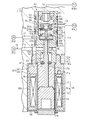
- FIG. 1 is a side sectional view of a variable displacement swash plate compressor according to an embodiment of the present invention.
- FIG. 2 is an enlarged side sectional view showing a part of the variable displacement swash plate type compressor.
- FIG. 5 is an enlarged side sectional view showing a part of the variable displacement swash plate compressor when the inclination angle of the swash plate is the maximum inclination angle.
- variable displacement swash plate type compressor is simply referred to as a compressor.
- a compressor is mounted in a vehicle and used for a vehicle air conditioner.
- the housing 11 of the compressor 10 has a cylinder block 12, a front housing 13 connected to the front end face of the cylinder block 12, and a rear end face of the cylinder block 12 via a valve / port former 14. And a rear housing 15 connected to each other.
- a space surrounded by the cylinder block 12 and the front housing 13 in the housing 11 is a crank chamber 16.
- the rotating shaft 17 is rotatably supported by the cylinder block 12 and the front housing 13.
- the lug plate 18 is rotatable integrally with the rotating shaft 17 in the crank chamber 16.
- the end of the rotary shaft 17 projecting from the housing 11 is connected to a vehicle engine E as an external drive source via a power transmission mechanism PT.
- the power transmission mechanism PT is a clutchless mechanism of a constant transmission type, for example, a combination of a belt and a pulley.
- the crank chamber 16 accommodates a swash plate 19 which is rotated by obtaining a driving force from the rotating shaft 17.
- the swash plate 19 is tiltable with respect to a plane orthogonal to the rotation axis L of the rotation shaft 17.
- the swash plate 19 is slidably supported by the rotating shaft 17 in the crank chamber 16.
- a biasing spring 20 for biasing the swash plate 19 is disposed between the lug plate 18 and the swash plate 19.
- the biasing spring 20 biases the swash plate 19 in the direction of decreasing the inclination angle.
- a hinge mechanism 21 is interposed between the lug plate 18 and the swash plate 19.
- the swash plate 19 is rotatable in synchronization with the lug plate 18 and the rotating shaft 17 by the biasing force of the biasing spring 20, the connection with the lug plate 18 by the hinge mechanism 21, and the support by the rotating shaft 17. It can also slide and tilt in the axial direction with respect to the rotating shaft 17.
- the plurality of cylinder bores 12 a pass through the cylinder block 12 in the axial direction and are arranged around the rotation axis 17.
- Each cylinder bore 12a accommodates the piston 22 in a reciprocating manner. Both openings of each cylinder bore 12 a are closed by the valve / port former 14 and the piston 22.
- a compression chamber 23 whose volume changes according to the reciprocation of the piston 22 is formed in each of the cylinder bores 12a.
- Each piston 22 is anchored to the outer peripheral portion of the swash plate 19 via a pair of shoes 24. When the swash plate 19 rotates with the rotation shaft 17, the rotational movement of the swash plate 19 is converted to reciprocating linear movement of the piston 22 via the shoes 24.
- a discharge chamber 25 is annularly formed between the rear housing 15 and the valve / port assembly 14.
- a suction chamber 26 is formed radially inward of the discharge chamber 25.
- a discharge port 25 h communicating with the discharge chamber 25 and a discharge valve 25 v opening and closing the discharge port 25 h are formed in the valve / port forming body 14.
- a suction port 26h communicating with the suction chamber 26 and a suction valve 26v opening and closing the suction port 26h are formed.
- the refrigerant in the suction chamber 26 is drawn into the cylinder bore 12a through the suction port 26h and the suction valve 26v by the movement from the top dead center to the bottom dead center of the piston 22.
- the refrigerant is carbon dioxide.
- the refrigerant drawn into the cylinder bore 12a is compressed to a predetermined pressure by the movement from the bottom dead center to the top dead center of the piston 22, and is discharged into the discharge chamber 25 through the discharge port 25h and the discharge valve 25v. Ru. Therefore, the suction chamber 26 is a suction pressure region, and the discharge chamber 25 is a discharge pressure region.
- a discharge passage 25 a communicating with the discharge chamber 25 and a suction passage 26 a communicating with the suction chamber 26 are formed in the rear housing 15.
- the discharge passage 25 a and the suction passage 26 a are connected to each other by the external refrigerant circuit 30.
- the external refrigerant circuit 30 includes a condenser 31 connected to the discharge passage 25a, an expansion valve 32 connected to the condenser 31, and an evaporator 33 connected to the expansion valve 32.
- the evaporator 33 is connected to the suction passage 26a.
- the compressor 10 constitutes a refrigerant circulation circuit of the vehicle air conditioner, that is, a cooling circuit.
- a throttle 34 is provided between the discharge passage 25 a and the condenser 31 in the discharge pressure region to reduce the discharge pulsation of the refrigerant gas.
- the refrigerant circulation circuit has a first pressure monitoring point P1 on the upstream side of the throttle 34 and a second pressure monitoring point P2 on the downstream side of the throttle 34 in the flow direction of the refrigerant gas circulating in the refrigerant circulation circuit.
- the pressure (PdH) of the first pressure monitoring point P1 is higher than the pressure (PdL) of the second pressure monitoring point P2.
- the crank chamber 16 and the suction chamber 26 are connected to each other via a bleed passage 35 passing through the cylinder block 12 and the valve / port assembly 14.
- the bleed passage 35 has a throttle.
- An electromagnetic displacement control valve 40 is attached to the rear housing 15.
- a notch 36 is formed in the bottom surface 15 e of the rear housing 15.
- the notch portion 36 has a first extending surface 36 a and a second extending surface 36 b.
- the first extending surface 36 a extends in a direction orthogonal to the bottom surface 15 e of the rear housing 15.
- the second extending surface 36b extends in a direction perpendicular to the first extending surface 36a.
- the second extending surface 36 b is continuous with both the first extending surface 36 a and the outer peripheral surface of the rear housing 15.
- An insertion hole 37 into which a part of the displacement control valve 40 is inserted is formed in the first extending surface 36 a.
- a female screw 37 a is formed in the vicinity of the first extending surface 36 a on the inner surface of the insertion hole 37.
- the displacement control valve 40 includes a solenoid unit 50 and a driving force transmission body 60.
- the driving force transmitting body 60 has a columnar shape and is driven by energization of the solenoid unit 50.
- the driving force transmission body 60 is made of stainless steel (SUS), and is formed of a material harder than copper.
- the displacement control valve 40 has a valve housing 40 h in which the first housing 41 and the cylindrical second housing 42 are assembled. The first housing 41 accommodates the driving force transmission body 60, and the second housing 42 accommodates the solenoid unit 50.
- the solenoid unit 50 has a fixed core 51 and a movable core 52.
- the movable core 52 is attracted to the stationary core 51 based on the excitation by the supply of the current to the coil 50a.
- the solenoid unit 50 operates by energization control (duty ratio control) of a control computer (not shown).
- the fixed core 51 is accommodated in the second housing 42 and disposed near the opening of the second housing 42 close to the first housing 41.
- the movable core 52 is disposed in the second housing 42 opposite to the first housing 41.
- An end 51 e of the stationary core 51 near the first housing 41 protrudes from the opening of the second housing 42.
- a flange 51 f protrudes from the outer surface of the end 51 e of the fixed core 51.
- the fixed iron core 51 and the movable iron core 52 are accommodated in a bottomed cylindrical case 53.
- the case 53 is inserted into the second housing 42 from the opening of the second housing 42 opposite to the first housing 41.
- a lid member 54 is attached to the second housing 42 so as to close an opening of the second housing 42 opposite to the first housing 41.
- the case 53 is fixed to the lid member 54 so as not to come off the lid member 54 by the circlip 53e.
- the first housing 41 includes a chamber forming housing 46 and a cylinder 47.
- a storage chamber 43, a valve chamber 44 and a pressure sensing chamber 45 are formed inside the chamber forming housing 46.
- the cylindrical body 47 is mounted on the outer surface of the end of the chamber forming housing 46 near the second housing 42.
- the cylindrical body 47 has a cylindrical portion 47 a inserted into the insertion hole 37 and an annular flange 47 b.
- the flange 47 b protrudes from the outer surface of the cylindrical portion 47 a near the second housing 42 in the direction orthogonal to the axis of the cylindrical portion 47 a.
- An external thread 47c screwed to the internal thread 37a is formed on the outer surface of the cylindrical portion 47a.
- An annular groove 47d is formed on the outer end surface of the flange 47b in the vicinity of the second housing 42, into which the second housing 42 is fitted. Further, from the inner peripheral surface of the cylindrical body 47, a locking projection 47f protrudes. The flange 51 f of the fixed core 51 is locked to the locking projection 47 f of the cylindrical body 47. Thereby, the fixed iron core 51 is attached to the inside of the cylindrical body 47.
- the storage chamber 43 is partitioned by a chamber forming housing 46 and a fixed iron core 51. Further, the valve chamber 44 is continuous with the fixed iron core 51 in the storage chamber 43 on the opposite side.
- the pressure sensing chamber 45 is provided to arrange the valve chamber 44 between the pressure sensing chamber 45 and the solenoid unit 50.
- a press-in recess 48 is formed between the pressure sensing chamber 45 and the valve chamber 44.
- An annular valve seat member 49 is press-fit into the press-fit recess 48.
- a valve hole 49 h is formed at a central portion of the valve seat member 49.
- the driving force transmission body 60 penetrates the fixed iron core 51 from the movable iron core 52 and passes through the storage chamber 43, the valve chamber 44, and the valve hole 49h and protrudes into the pressure sensitive chamber 45.
- the end face of the driving force transmitter 60 near the movable core 52 is in contact with the movable core 52.
- the driving force transmission body 60 has a valve body 60v.
- the valve body 60 v is accommodated in the valve chamber 44 and reciprocates in the valve chamber 44.
- the valve body 60v has an end face seal portion 60s.
- the end face seal portion 60s abuts on the end face of the valve seat member 49 near the valve chamber 44, and specifically abuts on the periphery of the valve hole 49h of the valve seat member 49.
- the driving force transmission body 60 has a columnar seal portion 60a.
- the seal portion 60a seals between the pressure sensitive chamber 45 and the valve hole 49h.
- the seal portion 60a protrudes into the pressure sensing chamber 45 from the valve hole 49h.
- the restriction ring 61 is mounted on the outer surface of a portion of the drive force transmission body 60 located in the storage chamber 43.
- a spring 62 is disposed in the storage chamber 43.
- the spring 62 is disposed between the restriction ring 61 and an end face 46 e opposite to the solenoid unit 50 in the accommodation chamber 43.
- the spring 62 biases the drive transmission body 60 toward the solenoid unit 50. Therefore, the spring 62 biases the movable core 52 away from the fixed core 51.
- the electromagnetic force of the solenoid unit 50 attracts the movable core 52 to the fixed core 51 against the biasing force of the spring 62.
- the pressure sensing mechanism 55 is accommodated in the pressure sensing chamber 45.
- the pressure sensing mechanism 55 has a bellows 56 made of copper, a cylindrical support 57 coupled to a first end of the bellows 56, and a pressure receiving body 58 coupled to a second end of the bellows 56.
- the bellows 56 can expand and contract in the moving direction of the valve body 60v.
- the pressure receiving body 58 is made of the same copper as the bellows 56 so as to facilitate the connection with the bellows 56.
- a recess 58 a is formed on the side of the pressure receiving body 58 opposite to the bellows 56.
- the pressure sensing mechanism 55 further includes a bellows cap 59.
- the bellows cap 59 is fitted into the recess 58 a of the pressure receiving body 58.
- the bellows cap 59 is formed of a flat abutted portion 59a and a fitting portion 59b projecting from the abutted portion 59a.
- the fitting portion 59b is formed in a tubular shape so as to be fitted into the recess 58a.
- the tip end of the seal portion 60 a of the driving force transmission body 60 forms an abutting portion 60 e.
- the tip end face of the contact portion 60 e is formed of a flat contact surface 60 d that contacts and separates from the bellows cap 59.
- the contact portion 60 e is integrally formed with the driving force transmission body 60.
- the surface of the abutted portion 59a of the bellows cap 59 in the vicinity of the driving force transfer member 60 forms a flat abutted surface 59d to which the abutted portion 60e abuts and separates. Therefore, the bellows cap 59 has a contact surface 59 d and constitutes a receiving portion coupled to the bellows 56 via the pressure receiving body 58.
- the abutting surface 60d of the abutting portion 60e and the abutted surface 59d of the bellows cap 59 abut on each other at flat surfaces.
- the bellows cap 59 is formed of a material harder than copper.
- the bellows cap 59 is made of stainless steel (SUS) which is the same material as the driving force transmission body 60. That is, the bellows cap 59 is formed of the same material as the contact portion 60e.
- the bellows cap 59 is formed of stainless steel having a Vickers hardness [HV] of 220 or more, and in the present embodiment, is formed of stainless steel having a Vickers hardness of 244.
- the driving force transmission body 60 is formed of stainless steel having a Vickers hardness of 1000 or more, and in the present embodiment, is formed of stainless steel having a Vickers hardness of 1160.
- a spring 45a is disposed in the pressure sensing chamber 45.
- the spring 45 a is disposed between the pressure receiving body 58 and the valve seat member 49.
- the spring 45 a biases the pressure receiving body 58 toward the support 57.
- the support 57 closes the opening of the chamber-forming housing 46.
- a cylindrical stopper 63 is fitted inside the support 57. Further, the pressure receiving body 58 is formed with a stopper 58 b that protrudes toward the stopper 63.
- the stopper 63 of the support 57 and the stopper 58 b of the pressure receiving body 58 define the shortest length of the bellows 56.
- the chamber formation housing 46 is formed with a first port 46 a communicating with the valve chamber 44.
- the valve chamber 44 communicates with the crank chamber 16 via the first port 46 a and the first passage 71.
- the chamber forming housing 46 and the valve seat member 49 are formed with a second port 46 b communicating with the valve hole 49 h.
- the valve hole 49 h communicates with the discharge chamber 25 via the second port 46 b and the second passage 72.
- the second passage 72, the second port 46b, the valve hole 49h, the valve chamber 44, the first port 46a and the first passage 71 form an air supply passage 75 extending from the discharge chamber 25 to the crank chamber 16.
- the air supply passage 75 is a connection passage connecting the discharge chamber 25 and the crank chamber 16.
- the volume control valve 40 is disposed on the air supply passage 75.
- the space in the bellows 56 is connected to the first pressure monitoring point P1 via the inner side of the stopper 63 and the third passage 73.
- the chamber forming housing 46 is provided with a third port 46 c communicating with the pressure sensitive chamber 45.
- the space of the pressure sensing chamber 45 is connected to the second pressure monitoring point P2 via the third port 46c and the fourth passage 74.
- the pressure sensing mechanism 55 is displaced in accordance with a differential pressure between two points which is a differential pressure between the pressure (PdH) at the first pressure monitoring point P1 and the pressure (PdL) at the second pressure monitoring point P2.
- the pressure (Pc) of the crank chamber 16 is controlled such that the displacement of the pressure sensing mechanism 55 changes the displacement to the side of canceling the fluctuation of the pressure difference between two points.
- a load based on the differential pressure between two points is applied to the driving force transmitting body 60 toward the solenoid unit 50.
- the driving force transmitter 60 moves toward the solenoid unit 50 by the load based on the differential pressure between the two points.
- the movable iron core 52 is separated from the fixed iron core 51 by the biasing force of the spring 62 in a state where the air conditioner switch of the compressor 10 is turned off and the energization to the solenoid unit 50 is stopped.
- the driving force transmitter 60 opens the valve hole 49 h by separating the end face seal portion 60 s of the valve body 60 v from the periphery of the valve hole 49 h of the valve seat member 49. Therefore, the valve body 60v is in an open state in which the air supply passage 75 is opened. Therefore, the refrigerant is supplied from the discharge chamber 25 to the crank chamber 16 through the air supply passage 75. Then, the pressure of the crank chamber 16 approaches the pressure (Pd) of the discharge chamber 25. As a result, the inclination angle of the swash plate 19 is reduced, the stroke of the piston 22 is reduced, and the displacement is reduced.
- the driving force transmitter 60 moves toward the pressure sensing chamber 45.
- the driving force transfer member 60 brings the end face seal portion 60s of the valve body 60v into contact with the periphery of the valve hole 49h of the valve seat member 49 to close the valve hole 49h.
- a force that opposes the load acting on the driving force transmitting body 60 based on the differential pressure between the two points is applied to the driving force transmitting body 60.
- valve body 60v is in a closed state in which the air supply passage 75 is closed. Therefore, the refrigerant is not supplied from the discharge chamber 25 to the crank chamber 16 via the air supply passage 75. Then, the refrigerant in the crank chamber 16 is discharged to the suction chamber 26 via the bleed passage 35, so the pressure in the crank chamber 16 approaches the pressure (Ps) in the suction chamber 26. As a result, the inclination angle of the swash plate 19 is increased, the stroke of the piston 22 is increased, and the displacement is increased.
- the crank chamber 16 functions as a control pressure chamber that changes the inclination angle of the swash plate 19. Further, the valve body 60v reciprocates to adjust the opening degree of the air supply passage 75.
- the displacement control valve 40 is disposed on the air supply passage 75, and the opening degree of the displacement control valve 40 is adjusted, whereby the discharge chamber 25 is supplied to the crank chamber 16 via the air supply passage 75. The amount of refrigerant supplied is controlled. In this way, so-called "entry side control" for controlling the pressure in the crank chamber 16 is performed.
- the corner portion of the abutting surface 60d of the abutting portion 60e abuts on the abutted surface 59d of the bellows cap 59, resulting in angular contact.
- the bellows cap 59 is formed of a material harder than copper. Therefore, compared with the case where the bellows cap 59 is made of the same copper as the bellows 56, even if the drive force transmission body 60 or the bellows cap 59 is inclined to cause angular contact as described above, the abutted surface 59d is less abraded .
- the pressure sensing mechanism 55 includes a bellows cap 59 coupled to the bellows 56.
- the driving force transmitting body 60 is provided with an abutting portion 60e having a flat abutting surface 60d which is in contact with and separated from the bellows cap 59.
- the bellows cap 59 includes an abutted portion 59a having a flat abutted surface 59d with which the abutted portion 60e abuts and is separated.
- the bellows cap 59 is formed of a material harder than copper.
- the driving force transmission body 60 or the bellows cap 59 is inclined, and the corner of the abutting surface 60d of the abutting portion 60e abuts on the abutted surface 59d of the bellows cap 59, resulting in angular contact. Also, the abutted surface 59d is hard to wear. Therefore, the opening degree of the valve body 60v can be adjusted with high accuracy.
- the bellows cap 59 is formed of the same material as the contact portion 60e. According to this, as compared with the case where the bellows cap 59 is formed of a material different from that of the contact portion 60e, the drive force transmission body 60 or the bellows cap 59 is inclined to form the contact surface 60d of the contact portion 60e. Even if the corner portion abuts on the abutted surface 59d of the bellows cap 59 and a corner abutment occurs, the abutted surface 60d and the abutted surface 59d are less likely to be worn away. Therefore, the opening degree of the valve body 60v can be adjusted with higher accuracy.
- the pressure sensing mechanism 55 includes a copper pressure receiving body 58 coupled to the bellows 56.
- the pressure receiving body 58 has a recess 58a.
- the bellows cap 59 is formed of an abutted portion 59a and a fitting portion 59b which protrudes from the abutted portion 59a and is fitted into the recess 58a. According to this configuration, the bellows cap 59 which is a material different from the copper bellows 56 can be coupled to the bellows 56 via the copper pressure receiver 58.
- the fitting portion 59b is cylindrical. According to this configuration, since the fitting portion 59b is thinned, weight reduction of the bellows cap 59 can be achieved as compared with the case where the fitting portion 59b is columnar.
- the above embodiment may be modified as follows.
- the bellows cap 59 may be made of, for example, a material different from that of the abutment portion 60e. The point is that the bellows cap 59 may be made of a material harder than copper.
- the contact portion 60 e may be a separate member from the driving force transmission body 60 and may be assembled to the driving force transmission body 60.
- the abutted portion 59 a may be a separate member from the bellows cap 59 and assembled to the bellows cap 59.
- the contact portion 60e may be, for example, a coating layer to which a DLC coating or the like is applied.
- the abutted portion 59a may be, for example, a coating layer to which a DLC coating or the like is applied.
- the fitting portion 59b may be, for example, in a columnar shape.
- the displacement control valve 40 may be disposed on a bleed passage, which is a connection passage connecting the suction chamber 26 and the crank chamber 16 in the suction pressure region.
- the amount of discharge of the refrigerant discharged from the crank chamber 16 to the suction chamber 26 may be controlled by adjusting the opening degree of the capacity control valve 40. That is, the compressor 10 may be configured to perform so-called "extraction side control" for controlling the pressure in the crank chamber 16.
- the bellows 56 may be configured to expand and contract in the moving direction of the valve body 60v by sensing the pressure in the suction pressure region.
- a control pressure chamber may be formed separately from the crank chamber 16, and the inclination angle of the swash plate 19 may be changed by controlling the pressure of the control pressure chamber.
- the power transmission mechanism PT may be a clutch mechanism capable of selecting transmission and disconnection of power by external electric control.
- the compressor 10 may be used for an air conditioner other than the vehicle air conditioner.
- the refrigerant may be, for example, fluorocarbon other than carbon dioxide.
Landscapes
- Engineering & Computer Science (AREA)
- Mechanical Engineering (AREA)
- General Engineering & Computer Science (AREA)
- Compressors, Vaccum Pumps And Other Relevant Systems (AREA)
- Magnetically Actuated Valves (AREA)
- Fluid-Driven Valves (AREA)
Abstract
感圧機構は、ベローズに結合されたベローズキャップを備える。駆動力伝達体は、ベローズキャップに接離する平坦な当接面を有する当接部を備える。ベローズキャップは、当接部が接離する平坦な被当接面を有する被当接部を備える。ベローズキャップは、銅よりも硬い材料から形成されている。
Description
本発明は、可変容量型斜板式圧縮機に用いられる容量制御弁に関する。
可変容量型斜板式圧縮機は、回転軸が回転可能に支持されるハウジングを有している。斜板は、回転軸から駆動力を得て回転する。また、可変容量型斜板式圧縮機は、制御圧室から吸入圧領域に至る抽気通路と、吐出圧領域から制御圧室に至る給気通路とを有する。容量制御弁が制御圧室の圧力を制御することにより、回転軸に対する斜板の傾斜角度が変更される。これにより、斜板に係留されたピストンが斜板の傾角に応じたストロークで往復動し、吐出容量が変更される。
容量制御弁は、ソレノイド部によって駆動される柱状の駆動力伝達体を有する。駆動力伝達体は、抽気通路又は給気通路の開度を調整する弁体を有する。また、容量制御弁は、感圧室が形成されたバルブハウジングを有する。感圧室には、感圧機構が収容されている。感圧機構は、弁体の移動方向に伸縮して弁体の開度を制御するベローズを有する。ベローズは銅製である。駆動力伝達体は、感圧室に突出している。感圧機構は、ベローズに結合されるとともに凹部を有する受け部を備えている。受け部は、ベローズとの結合が容易となるようにベローズと同じ銅製である。
感圧室に突出する駆動力伝達体の端部は、受け部の凹部にスライド可能に嵌入されている。感圧室に突出する駆動力伝達体の端面(当接面)は、平坦面である。ここで、駆動力伝達体と受け部とが結合していると、以下の問題が生じる。例えば、ソレノイド部への通電が停止されている場合であっても、感圧室の圧力が変動してベローズが伸縮すると、ベローズの伸縮に追従して駆動力伝達体が移動する。このため、弁体が意図しない位置に配置される虞がある。このため、駆動力伝達体の端面は、受け部の凹部の底面(被当接面)と接離可能になっている。弁体の開度は、ソレノイド部で生じる電磁力や、感圧機構において弁体を閉弁する方向に作用する付勢力等のバランスによって決まる。
駆動力伝達体の端面と受け部の凹部の底面とは、平面同士で当接する。ここで、駆動力伝達体又は受け部が傾くと、駆動力伝達体の端面の角部が受け部の凹部の底面に当接して、角当たりが生じる。その結果、受け部の凹部の底面が摩耗し易い。そこで、受け部の凹部の底面の摩耗を抑制する構成が、例えば、特許文献1に開示されている。特許文献1の容量制御弁は、受け部の凹部内に圧入された鋼球を有することで、駆動力伝達体の端面と鋼球とを接離可能に構成されている。鋼球の球面と駆動力伝達体の平坦な端面との当接は、局所的な面接触であるものの、上記の角当たりとは異なる。このため、受け部の凹部の底面の摩耗が抑制される。
しかしながら、特許文献1の容量制御弁では、駆動力伝達体又は受け部が傾いていない状態でも、鋼球の球面と駆動力伝達体の端面とが局所的に面接触する。このため、平面同士で当接する場合に比べると、受け部の凹部の底面は摩耗し易い。受け部の凹部の底面が摩耗すると、弁体の開度を精度良く調整することができなくなる。
本発明の目的は、弁体の開度を精度良く調整することができる容量制御弁を提供することにある。
上記課題を解決するため、本願発明の第一の態様によれば、可変容量型斜板式圧縮機に用いられる容量制御弁が提供される。可変容量型斜板式圧縮機は、制御圧室の圧力を制御することにより斜板の傾角が変更されて、ピストンが斜板の傾角に応じたストロークで往復動する。容量制御弁は、ソレノイド部と、ソレノイド部によって駆動され、弁体を有する柱状の駆動力伝達体であって、弁体は、吐出圧領域又は吸入圧領域と制御圧室とを接続する接続通路の開度を調節するために往復移動する、駆動力伝達体と、感圧室を有するバルブハウジングと、感圧室に収容され、銅製のベローズを有する感圧機構であって、ベローズは、弁体の移動方向に伸縮して弁体の開度を制御する、感圧機構とを備える。駆動力伝達体は、感圧室に突出し、感圧機構は、ベローズに結合された受け部を備え、駆動力伝達体は、受け部に接離する平坦な当接面を有する当接部を備え、受け部は、当接部が接離する平坦な被当接面を有する被当接部を備え、当接部及び被当接部は、銅よりも硬い材料から形成されている。
以下、本発明の可変容量型斜板式圧縮機に用いられる容量制御弁を具体化した一実施形態を図1~図3にしたがって説明する。可変容量型斜板式圧縮機は、単に、圧縮機と称す。圧縮機は、車両に搭載され、車両空調装置に用いられる。
図1に示すように、圧縮機10のハウジング11は、シリンダブロック12と、シリンダブロック12の前端面に連結されたフロントハウジング13と、シリンダブロック12の後端面に弁・ポート形成体14を介して連結されたリヤハウジング15とを備えている。ハウジング11内のシリンダブロック12とフロントハウジング13とにより囲まれた空間は、クランク室16である。回転軸17は、シリンダブロック12及びフロントハウジング13により回転可能に支持されている。ラグプレート18は、クランク室16内において、回転軸17と一体的に回転可能である。
ハウジング11から突出した回転軸17の端部は、動力伝達機構PTを介して、外部駆動源としての車両用エンジンEに連結されている。動力伝達機構PTは、常時伝達型のクラッチレス機構、例えば、ベルト及びプーリの組合せである。
クランク室16には、回転軸17から駆動力を得て回転する斜板19が収容されている。斜板19は、回転軸17の回転軸線Lに直交する面に対して傾動可能である。斜板19は、クランク室16内において、スライド移動可能に回転軸17に支持されている。ラグプレート18と斜板19との間には、斜板19を付勢する付勢ばね20が配置されている。付勢ばね20は、斜板19の傾角を減少させる方向に付勢する。さらに、ラグプレート18と斜板19との間には、ヒンジ機構21が介在されている。斜板19は、付勢ばね20の付勢力と、ヒンジ機構21によるラグプレート18との連結と、回転軸17による支持とによって、ラグプレート18及び回転軸17と同期して回転可能であり、回転軸17に対してその軸方向にスライド移動し傾動可能でもある。
シリンダブロック12には、複数(図1では1つのシリンダボア12aのみ示す)のシリンダボア12aが形成されている。複数のシリンダボア12aは、シリンダブロック12を軸方向に貫通し、かつ回転軸17の周囲に配列されている。各シリンダボア12aは、ピストン22を往復動可能にそれぞれ収納する。各シリンダボア12aの両開口は、弁・ポート形成体14及びピストン22によって閉塞されている。各シリンダボア12a内には、ピストン22の往復動に応じて体積が変化する圧縮室23が形成されている。各ピストン22は、一対のシュー24を介して斜板19の外周部に係留されている。回転軸17と共に斜板19が回転すると、斜板19の回転運動は、シュー24を介してピストン22の往復直線運動に変換される。
リヤハウジング15と弁・ポート形成体14との間には、吐出室25が環状に形成されている。吐出室25の径方向内側には、吸入室26が形成されている。弁・ポート形成体14には、吐出室25に連通する吐出ポート25h、及び吐出ポート25hを開閉する吐出弁25vが形成されている。弁・ポート形成体14には、吸入室26に連通する吸入ポート26h、及び吸入ポート26hを開閉する吸入弁26vが形成されている。
吸入室26の冷媒は、ピストン22の上死点から下死点への移動により、吸入ポート26h及び吸入弁26vを介してシリンダボア12aに吸入される。本実施形態において、冷媒は二酸化炭素である。シリンダボア12aに吸入された冷媒は、ピストン22の下死点から上死点への移動により、所定の圧力にまで圧縮されるとともに、吐出ポート25h及び吐出弁25vを介して吐出室25に吐出される。よって、吸入室26は吸入圧領域であり、吐出室25は吐出圧領域である。
リヤハウジング15には、吐出室25に連通する吐出通路25aと、吸入室26に連通する吸入通路26aとが形成されている。吐出通路25a及び吸入通路26aは、外部冷媒回路30によって互いに接続されている。外部冷媒回路30は、吐出通路25aに接続された凝縮器31、凝縮器31に接続された膨張弁32、及び膨張弁32に接続された蒸発器33を備えている。蒸発器33は、吸入通路26aに接続されている。圧縮機10は、車両空調装置の冷媒循環回路、即ち、冷房回路を構成する。
吐出圧領域内の吐出通路25aと凝縮器31との間には、冷媒ガスの吐出脈動を低減する絞り34が設けられている。冷媒循環回路を循環する冷媒ガスの流通方向において、冷媒循環回路は、絞り34の上流側に第1圧力監視点P1を有し、絞り34の下流側に第2圧力監視点P2を有する。第1圧力監視点P1の圧力(PdH)は、第2圧力監視点P2の圧力(PdL)よりも高い。
クランク室16と吸入室26とは、シリンダブロック12及び弁・ポート形成体14を貫通する抽気通路35を介して、互いに接続されている。抽気通路35は絞りを有する。リヤハウジング15には、電磁式の容量制御弁40が取り付けられている。
図2及び図3に示すように、リヤハウジング15の底面15eには、切欠部36が形成されている。切欠部36は、第1延設面36aと、第2延設面36bとを有する。第1延設面36aは、リヤハウジング15の底面15eに対して直交する方向に延びている。第2延設面36bは、第1延設面36aに対して直交する方向に延びている。第2延設面36bは、第1延設面36a及びリヤハウジング15の外周面のいずれにも連続している。第1延設面36aには、容量制御弁40の一部が挿入される挿入孔37が形成されている。挿入孔37の内面における第1延設面36a近傍には、雌ねじ37aが形成されている。
容量制御弁40は、ソレノイド部50と、駆動力伝達体60とを備えている。駆動力伝達体60は、柱状であり、ソレノイド部50の通電によって駆動される。駆動力伝達体60は、ステンレス鋼(SUS)製であり、銅よりも硬い材料から形成されている。容量制御弁40は、第1ハウジング41と筒状の第2ハウジング42とを組み付けてなるバルブハウジング40hを有している。第1ハウジング41は駆動力伝達体60を収容し、第2ハウジング42はソレノイド部50を収容する。
ソレノイド部50は、固定鉄心51と、可動鉄心52とを有する。可動鉄心52は、コイル50aへの電流の供給による励磁に基づいて、固定鉄心51に引き付けられる。ソレノイド部50は、図示しない制御コンピュータの通電制御(デューティ比制御)により作動する。固定鉄心51は、第2ハウジング42内に収容され、第1ハウジング41に近い第2ハウジング42の開口付近に配置されている。可動鉄心52は、第2ハウジング42内における第1ハウジング41とは反対側に配置されている。第1ハウジング41近傍の固定鉄心51の端部51eは、第2ハウジング42の開口から突出している。固定鉄心51の端部51eの外面からは、フランジ51fが突出している。
固定鉄心51及び可動鉄心52は、有底筒状のケース53に収容されている。ケース53は、第2ハウジング42における第1ハウジング41とは反対側の開口から、第2ハウジング42内に挿入されている。第2ハウジング42には、第1ハウジング41とは反対側の第2ハウジング42の開口を塞ぐように蓋部材54が装着されている。ケース53は、サークリップ53eによって蓋部材54から抜けないように、蓋部材54に固定されている。
第1ハウジング41は、室形成ハウジング46と、筒体47とを備えている。室形成ハウジング46の内部には、収容室43、弁室44及び感圧室45が形成されている。筒体47は、第2ハウジング42近傍の室形成ハウジング46の端部の外面に装着されている。筒体47は、挿入孔37に挿入される筒部47aと、環状のフランジ47bとを有する。フランジ47bは、第2ハウジング42近傍の筒部47aの外面から、筒部47aの軸線と直交する方向に突出している。筒部47aの外面には、雌ねじ37aに螺合する雄ねじ47cが形成されている。
第2ハウジング42近傍のフランジ47bの外端面には、第2ハウジング42が外嵌される環状の溝部47dが形成されている。さらに、筒体47の内周面からは、係止突起47fが突出している。固定鉄心51のフランジ51fは、筒体47の係止突起47fに係止されている。これにより、固定鉄心51が、筒体47の内側に取り付けられている。
収容室43は、室形成ハウジング46と固定鉄心51とによって区画されている。また、弁室44は、収容室43における固定鉄心51とは反対側に連続している。感圧室45は、感圧室45とソレノイド部50との間に弁室44を配置するように、設けられている。感圧室45と弁室44との間には、圧入凹部48が形成されている。圧入凹部48には、環状の弁座部材49が圧入されている。弁座部材49の中央部には、弁孔49hが形成されている。
駆動力伝達体60は、可動鉄心52から固定鉄心51を貫通するとともに、収容室43、弁室44及び弁孔49hを通過して、感圧室45に突出している。可動鉄心52近傍の駆動力伝達体60の端面は、可動鉄心52に当接している。駆動力伝達体60は、弁体60vを有する。弁体60vは、弁室44内に収容され、弁室44内を往復移動する。弁体60vは、端面シール部60sを有する。端面シール部60sは、弁室44近傍の弁座部材49の端面に当接し、具体的には、弁座部材49の弁孔49hの周囲に当接する。
駆動力伝達体60は、柱状のシール部60aを有する。シール部60aは、感圧室45と弁孔49hとの間をシールする。シール部60aは、弁孔49hから感圧室45内に突出している。規制リング61は、駆動力伝達体60の収容室43内に位置する部位の外面に装着されている。収容室43内には、ばね62が配置されている。ばね62は、規制リング61と、収容室43内におけるソレノイド部50とは反対側の端面46eとの間に配置されている。ばね62は、駆動力伝達体60をソレノイド部50に向けて付勢する。したがって、ばね62は、可動鉄心52を固定鉄心51から遠ざけるように付勢している。ソレノイド部50の電磁力は、ばね62の付勢力に抗して、可動鉄心52を固定鉄心51に引き付ける。
感圧室45には、感圧機構55が収容されている。感圧機構55は、銅製のベローズ56と、ベローズ56の第1端部に結合された筒状の支持体57と、ベローズ56の第2端部に結合された受圧体58とを有する。ベローズ56は、弁体60vの移動方向に伸縮可能である。受圧体58は、ベローズ56との結合が容易となるようにベローズ56と同じ銅製である。
受圧体58におけるベローズ56とは反対側には、凹部58aが形成されている。感圧機構55は、更に、ベローズキャップ59を備えている。ベローズキャップ59は、受圧体58の凹部58aに嵌め込まれている。ベローズキャップ59は、平板状の被当接部59aと、被当接部59aから突出する嵌込部59bとから形成されている。嵌込部59bは、凹部58aに嵌め込まれるよう筒状に形成されている。
駆動力伝達体60のシール部60aの先端部は、当接部60eを形成している。当接部60eの先端面は、ベローズキャップ59に接離する平坦な当接面60dからなる。よって、当接部60eは、駆動力伝達体60に一体形成されている。駆動力伝達体60近傍のベローズキャップ59の被当接部59aの表面は、当接部60eが接離する平坦な被当接面59dを形成している。よって、ベローズキャップ59は、被当接面59dを有するとともに受圧体58を介してベローズ56に結合された受け部を構成している。当接部60eの当接面60dとベローズキャップ59の被当接面59dとは、平面同士で当接する。
ベローズキャップ59は、銅よりも硬い材料から形成されている。本実施形態において、ベローズキャップ59は、駆動力伝達体60と同じ材料であるステンレス鋼(SUS)からなる。つまり、ベローズキャップ59は、当接部60eと同じ材料から形成されている。ベローズキャップ59は、ビッカース硬度[HV]が220以上のステンレス鋼から形成され、本実施形態では、ビッカース硬度が244のステンレス鋼から形成されている。また、駆動力伝達体60は、ビッカース硬度が1000以上のステンレス鋼から形成され、本実施形態では、ビッカース硬度が1160のステンレス鋼から形成されている。
感圧室45内には、ばね45aが配置されている。ばね45aは、受圧体58と弁座部材49との間に配置されている。ばね45aは、受圧体58を支持体57に向けて付勢する。支持体57は、室形成ハウジング46の開口を閉鎖している。
支持体57の内側には、筒状のストッパ63が嵌入されている。また、受圧体58には、ストッパ63に向けて突出するストッパ58bが形成されている。支持体57のストッパ63と受圧体58のストッパ58bとは、ベローズ56の最短長を規定している。
室形成ハウジング46には、弁室44に連通する第1ポート46aが形成されている。弁室44は、第1ポート46a及び第1通路71を介してクランク室16に連通している。室形成ハウジング46及び弁座部材49には、弁孔49hに連通する第2ポート46bが形成されている。弁孔49hは、第2ポート46b及び第2通路72を介して吐出室25に連通している。第2通路72、第2ポート46b、弁孔49h、弁室44、第1ポート46a及び第1通路71は、吐出室25からクランク室16に至る給気通路75を形成している。よって、給気通路75は、吐出室25とクランク室16とを接続する接続通路である。容量制御弁40は、給気通路75上に配置されている。
ベローズ56内の空間は、ストッパ63の内側及び第3通路73を介して、第1圧力監視点P1に接続されている。室形成ハウジング46には、感圧室45に連通する第3ポート46cが形成されている。感圧室45の空間は、第3ポート46c及び第4通路74を介して、第2圧力監視点P2に接続されている。感圧機構55は、第1圧力監視点P1の圧力(PdH)と第2圧力監視点P2の圧力(PdL)との差圧である二点間差圧に応じて変位する。感圧機構55の変位によって、二点間差圧の変動を打ち消す側に吐出容量が変更されるように、クランク室16の圧力(Pc)が制御される。駆動力伝達体60には、二点間差圧に基づく荷重がソレノイド部50に向けて付与される。この二点間差圧に基づく荷重によって、駆動力伝達体60は、ソレノイド部50に向けて移動する。
図2に示すように、圧縮機10のエアコンスイッチがOFFされてソレノイド部50への通電が停止されている状態で、可動鉄心52は、ばね62の付勢力によって固定鉄心51から離間している。このとき、駆動力伝達体60は、弁体60vの端面シール部60sを弁座部材49の弁孔49hの周囲から離間させることにより、弁孔49hを開放している。よって、弁体60vは、給気通路75を開放する開弁状態となる。このため、冷媒が給気通路75を介して吐出室25からクランク室16へ供給される。そして、クランク室16の圧力が吐出室25の圧力(Pd)に近づく。これにより、斜板19の傾角が小さくなり、ピストン22のストロークが小さくなり、吐出容量が減少する。
図3に示すように、エアコンスイッチがONされてソレノイド部50への通電が行われると、可動鉄心52は、ソレノイド部50で生じる電磁力によって、ばね62の付勢力に抗して固定鉄心51に引き付けられる。これにより、駆動力伝達体60は、感圧室45に向けて移動する。その結果、駆動力伝達体60は、弁体60vの端面シール部60sを弁座部材49の弁孔49hの周囲に当接させて、弁孔49hを閉鎖する。このとき、ソレノイド部50への通電が行われることで、二点間差圧に基づき駆動力伝達体60に作用する荷重と対抗する力が、駆動力伝達体60に付与される。よって、弁体60vは、給気通路75を閉鎖する閉弁状態となる。このため、冷媒が給気通路75を介して吐出室25からクランク室16へ供給されなくなる。すると、クランク室16内の冷媒が抽気通路35を介して吸入室26に排出されるため、クランク室16の圧力が吸入室26の圧力(Ps)に近づく。その結果、斜板19の傾角が大きくなり、ピストン22のストロークが大きくなり、吐出容量が増大する。
クランク室16は、斜板19の傾角を変更させる制御圧室として機能している。また、弁体60vは、給気通路75の開度を調節するために往復移動する。本実施形態では、給気通路75上に容量制御弁40を配置し、容量制御弁40の開度を調節することで、吐出室25から給気通路75を介してクランク室16に供給される冷媒の供給量が制御される。こうして、クランク室16の圧力を制御する、所謂「入れ側制御」が行われる。
次に、上記の圧縮機10の作用について、図2を参照して説明する。
図2に示すように、駆動力伝達体60とベローズキャップ59とが結合していると、以下の問題が生じる。例えば、エアコンスイッチがOFFされてソレノイド部50への通電が停止されている場合であっても、感圧室45の圧力が変動してベローズ56が伸縮すると、ベローズ56の伸縮に追従して駆動力伝達体60が移動する。このため、弁体60vが意図しない位置に配置される虞がある。このため、駆動力伝達体60の当接部60eは、ベローズキャップ59と接離可能になっている。ここで、駆動力伝達体60又はベローズキャップ59が傾くと、当接部60eの当接面60dの角部がベローズキャップ59の被当接面59dに当接して、角当たりが生じる。ここで、ベローズキャップ59は、銅よりも硬い材料から形成されている。よって、ベローズキャップ59がベローズ56と同じ銅製である場合に比べると、駆動力伝達体60又はベローズキャップ59が傾いて上記のように角当たりが生じても、被当接面59dが摩耗し難い。
図2に示すように、駆動力伝達体60とベローズキャップ59とが結合していると、以下の問題が生じる。例えば、エアコンスイッチがOFFされてソレノイド部50への通電が停止されている場合であっても、感圧室45の圧力が変動してベローズ56が伸縮すると、ベローズ56の伸縮に追従して駆動力伝達体60が移動する。このため、弁体60vが意図しない位置に配置される虞がある。このため、駆動力伝達体60の当接部60eは、ベローズキャップ59と接離可能になっている。ここで、駆動力伝達体60又はベローズキャップ59が傾くと、当接部60eの当接面60dの角部がベローズキャップ59の被当接面59dに当接して、角当たりが生じる。ここで、ベローズキャップ59は、銅よりも硬い材料から形成されている。よって、ベローズキャップ59がベローズ56と同じ銅製である場合に比べると、駆動力伝達体60又はベローズキャップ59が傾いて上記のように角当たりが生じても、被当接面59dが摩耗し難い。
上記実施形態では、以下の効果を得ることができる。
(1)感圧機構55は、ベローズ56に結合されたベローズキャップ59を備えている。駆動力伝達体60は、ベローズキャップ59に接離する平坦な当接面60dを有する当接部60eを備えている。ベローズキャップ59は、当接部60eが接離する平坦な被当接面59dを有する被当接部59aを備えている。ベローズキャップ59は、銅よりも硬い材料から形成されている。この構成によれば、駆動力伝達体60又はベローズキャップ59が傾いて、当接部60eの当接面60dの角部がベローズキャップ59の被当接面59dに当接し、角当たりが生じても、被当接面59dが摩耗し難い。このため、弁体60vの開度を精度良く調整することができる。
(1)感圧機構55は、ベローズ56に結合されたベローズキャップ59を備えている。駆動力伝達体60は、ベローズキャップ59に接離する平坦な当接面60dを有する当接部60eを備えている。ベローズキャップ59は、当接部60eが接離する平坦な被当接面59dを有する被当接部59aを備えている。ベローズキャップ59は、銅よりも硬い材料から形成されている。この構成によれば、駆動力伝達体60又はベローズキャップ59が傾いて、当接部60eの当接面60dの角部がベローズキャップ59の被当接面59dに当接し、角当たりが生じても、被当接面59dが摩耗し難い。このため、弁体60vの開度を精度良く調整することができる。
(2)ベローズキャップ59は、当接部60eと同じ材料から形成されている。これによれば、ベローズキャップ59が当接部60eとは異なる材料から形成されている場合に比べると、駆動力伝達体60又はベローズキャップ59が傾いて、当接部60eの当接面60dの角部がベローズキャップ59の被当接面59dに当接して、角当たりが生じても、当接面60d及び被当接面59dが摩耗し難い。よって、弁体60vの開度を更に精度良く調整することができる。
(3)感圧機構55は、ベローズ56に結合された銅製の受圧体58を備えている。受圧体58は、凹部58aを有している。ベローズキャップ59は、被当接部59aと、被当接部59aから突出するとともに凹部58aに嵌め込まれる嵌込部59bとから形成されている。この構成によれば、銅製であるベローズ56とは異なる材料であるベローズキャップ59を、銅製の受圧体58を介してベローズ56に結合することができる。
(4)嵌込部59bは、筒状である。この構成によれば、嵌込部59bが肉抜きされているため、嵌込部59bが柱状である場合に比べて、ベローズキャップ59の軽量化を図ることができる。
上記実施形態は、以下のように変更してもよい。
ベローズキャップ59を、例えば、当接部60eとは異なる材料から形成してもよい。要は、ベローズキャップ59が、銅よりも硬い材料から形成されていればよい。
ベローズキャップ59を、例えば、当接部60eとは異なる材料から形成してもよい。要は、ベローズキャップ59が、銅よりも硬い材料から形成されていればよい。
当接部60eを、駆動力伝達体60とは別部材とし、駆動力伝達体60に組み付けてもよい。
被当接部59aを、ベローズキャップ59とは別部材とし、ベローズキャップ59に組み付けてもよい。
被当接部59aを、ベローズキャップ59とは別部材とし、ベローズキャップ59に組み付けてもよい。
当接部60eは、例えば、DLCコーティング等が施されたコーティング層であってもよい。
被当接部59aは、例えば、DLCコーティング等が施されたコーティング層であってもよい。
被当接部59aは、例えば、DLCコーティング等が施されたコーティング層であってもよい。
嵌込部59bは、例えば、柱状であってもよい。
吸入圧領域である吸入室26とクランク室16とを接続する接続通路である抽気通路上に、容量制御弁40を配置してもよい。この場合、容量制御弁40の開度を調節して、クランク室16から抽気通路を介して吸入室26に排出される冷媒の排出量を制御すればよい。即ち、クランク室16の圧力を制御する、所謂「抜き側制御」を行うように、圧縮機10を構成してもよい。
吸入圧領域である吸入室26とクランク室16とを接続する接続通路である抽気通路上に、容量制御弁40を配置してもよい。この場合、容量制御弁40の開度を調節して、クランク室16から抽気通路を介して吸入室26に排出される冷媒の排出量を制御すればよい。即ち、クランク室16の圧力を制御する、所謂「抜き側制御」を行うように、圧縮機10を構成してもよい。
ベローズ56を、吸入圧領域の圧力を感知して弁体60vの移動方向に伸縮するように構成してもよい。
クランク室16とは別に制御圧室を形成し、制御圧室の圧力を制御することで斜板19の傾角を変更してもよい。
クランク室16とは別に制御圧室を形成し、制御圧室の圧力を制御することで斜板19の傾角を変更してもよい。
動力伝達機構PTは、外部からの電気制御によって動力の伝達及び遮断を選択可能なクラッチ機構であってもよい。
圧縮機10を、車両空調装置以外の空調装置に用いてもよい。
圧縮機10を、車両空調装置以外の空調装置に用いてもよい。
冷媒は、二酸化炭素以外に、例えば、フロンであってもよい。
Claims (3)
- 可変容量型斜板式圧縮機に用いられる容量制御弁であって、前記可変容量型斜板式圧縮機は、制御圧室の圧力を制御することにより斜板の傾角が変更されて、ピストンが前記斜板の傾角に応じたストロークで往復動する、容量制御弁において、
ソレノイド部と、
前記ソレノイド部によって駆動され、弁体を有する柱状の駆動力伝達体であって、前記弁体は、吐出圧領域又は吸入圧領域と前記制御圧室とを接続する接続通路の開度を調節するために往復移動する、駆動力伝達体と、
感圧室を有するバルブハウジングと、
前記感圧室に収容され、銅製のベローズを有する感圧機構であって、前記ベローズは、前記弁体の移動方向に伸縮して前記弁体の開度を制御する、感圧機構と
を備え、
前記駆動力伝達体は、前記感圧室に突出し、
前記感圧機構は、前記ベローズに結合された受け部を備え、
前記駆動力伝達体は、前記受け部に接離する平坦な当接面を有する当接部を備え、
前記受け部は、前記当接部が接離する平坦な被当接面を有する被当接部を備え、
前記当接部及び前記被当接部は、銅よりも硬い材料から形成されている、容量制御弁。 - 請求項1に記載の容量制御弁において、
前記被当接部は、前記当接部と同じ材料から形成されている、容量制御弁。 - 請求項1又は2に記載の容量制御弁において、
前記感圧機構は、前記ベローズに結合された銅製の受圧体を備え、
前記受圧体は凹部を有し、
前記受け部は、前記被当接部と、前記被当接部から突出するとともに前記凹部に嵌め込まれる嵌込部とから形成されている、記載の容量制御弁。
Priority Applications (1)
| Application Number | Priority Date | Filing Date | Title |
|---|---|---|---|
| DE112016004205.1T DE112016004205B4 (de) | 2015-09-16 | 2016-09-15 | Hubsteuerventil in einem Taumelscheibenkompressor mit einem Kupferbalg als Druckmessmechanismus |
Applications Claiming Priority (2)
| Application Number | Priority Date | Filing Date | Title |
|---|---|---|---|
| JP2015-182902 | 2015-09-16 | ||
| JP2015182902A JP6141930B2 (ja) | 2015-09-16 | 2015-09-16 | 容量制御弁 |
Publications (1)
| Publication Number | Publication Date |
|---|---|
| WO2017047720A1 true WO2017047720A1 (ja) | 2017-03-23 |
Family
ID=58289328
Family Applications (1)
| Application Number | Title | Priority Date | Filing Date |
|---|---|---|---|
| PCT/JP2016/077339 Ceased WO2017047720A1 (ja) | 2015-09-16 | 2016-09-15 | 容量制御弁 |
Country Status (3)
| Country | Link |
|---|---|
| JP (1) | JP6141930B2 (ja) |
| DE (1) | DE112016004205B4 (ja) |
| WO (1) | WO2017047720A1 (ja) |
Families Citing this family (3)
| Publication number | Priority date | Publication date | Assignee | Title |
|---|---|---|---|---|
| JP6875201B2 (ja) * | 2017-06-02 | 2021-05-19 | サンデンホールディングス株式会社 | 背圧制御弁及びスクロール型圧縮機 |
| JP6871810B2 (ja) * | 2017-06-19 | 2021-05-12 | サンデン・オートモーティブコンポーネント株式会社 | 可変容量圧縮機の制御弁 |
| EP3744978B1 (en) * | 2018-01-26 | 2023-11-15 | Eagle Industry Co., Ltd. | Capacity control valve |
Citations (6)
| Publication number | Priority date | Publication date | Assignee | Title |
|---|---|---|---|---|
| JP2002221153A (ja) * | 2001-01-23 | 2002-08-09 | Toyota Industries Corp | 容量可変型圧縮機の制御弁 |
| JP2002332962A (ja) * | 2001-05-10 | 2002-11-22 | Toyota Industries Corp | 容量可変型圧縮機の制御弁 |
| JP2006029144A (ja) * | 2004-07-13 | 2006-02-02 | Sanden Corp | 可変容量斜板式圧縮機の容量制御弁 |
| JP2006097665A (ja) * | 2004-06-28 | 2006-04-13 | Toyota Industries Corp | 可変容量型圧縮機における容量制御弁 |
| JP2009079530A (ja) * | 2007-09-26 | 2009-04-16 | Sanden Corp | 容量制御弁及びこれを用いた可変容量圧縮機 |
| JP2015094294A (ja) * | 2013-11-12 | 2015-05-18 | 株式会社豊田自動織機 | 容量制御弁 |
Family Cites Families (2)
| Publication number | Priority date | Publication date | Assignee | Title |
|---|---|---|---|---|
| JP2000283048A (ja) | 1999-03-29 | 2000-10-10 | Toyota Autom Loom Works Ltd | 電気式容量制御弁及び可変容量型圧縮機 |
| JP2002089442A (ja) | 2000-09-08 | 2002-03-27 | Toyota Industries Corp | 容量可変型圧縮機の制御弁 |
-
2015
- 2015-09-16 JP JP2015182902A patent/JP6141930B2/ja active Active
-
2016
- 2016-09-15 DE DE112016004205.1T patent/DE112016004205B4/de active Active
- 2016-09-15 WO PCT/JP2016/077339 patent/WO2017047720A1/ja not_active Ceased
Patent Citations (6)
| Publication number | Priority date | Publication date | Assignee | Title |
|---|---|---|---|---|
| JP2002221153A (ja) * | 2001-01-23 | 2002-08-09 | Toyota Industries Corp | 容量可変型圧縮機の制御弁 |
| JP2002332962A (ja) * | 2001-05-10 | 2002-11-22 | Toyota Industries Corp | 容量可変型圧縮機の制御弁 |
| JP2006097665A (ja) * | 2004-06-28 | 2006-04-13 | Toyota Industries Corp | 可変容量型圧縮機における容量制御弁 |
| JP2006029144A (ja) * | 2004-07-13 | 2006-02-02 | Sanden Corp | 可変容量斜板式圧縮機の容量制御弁 |
| JP2009079530A (ja) * | 2007-09-26 | 2009-04-16 | Sanden Corp | 容量制御弁及びこれを用いた可変容量圧縮機 |
| JP2015094294A (ja) * | 2013-11-12 | 2015-05-18 | 株式会社豊田自動織機 | 容量制御弁 |
Also Published As
| Publication number | Publication date |
|---|---|
| JP2017057784A (ja) | 2017-03-23 |
| DE112016004205T5 (de) | 2018-06-07 |
| DE112016004205B4 (de) | 2023-05-25 |
| JP6141930B2 (ja) | 2017-06-07 |
Similar Documents
| Publication | Publication Date | Title |
|---|---|---|
| JP6115393B2 (ja) | 可変容量型斜板式圧縮機 | |
| US9518568B2 (en) | Swash plate type variable displacement compressor | |
| JP6135521B2 (ja) | 可変容量型斜板式圧縮機 | |
| US8128061B2 (en) | Capacity control valve | |
| US9581149B2 (en) | Double-headed piston type swash plate compressor | |
| US20150104334A1 (en) | Variable displacement swash plate compressor | |
| US20150275874A1 (en) | Variable displacement type swash plate compressor | |
| JP2015178795A (ja) | 容量制御弁 | |
| US20110091334A1 (en) | Variable Displacement Compressor | |
| JP2014118939A (ja) | 可変容量型斜板式圧縮機 | |
| JP2009221965A (ja) | 可変容量圧縮機の容量制御弁及び往復動型可変容量圧縮機 | |
| WO2017047720A1 (ja) | 容量制御弁 | |
| JP6127999B2 (ja) | 可変容量型斜板式圧縮機 | |
| JP7220963B2 (ja) | 容量制御弁 | |
| JP6264312B2 (ja) | 可変容量型斜板式圧縮機 | |
| JP2017133393A (ja) | 可変容量型斜板式圧縮機 | |
| JP5888223B2 (ja) | 可変容量型斜板式圧縮機 | |
| US20170145997A1 (en) | Variable displacement type swash plate compressor | |
| CN110770440B (zh) | 可变容量压缩机的控制阀 | |
| KR101750318B1 (ko) | 용량 가변형 사판식 압축기 | |
| WO2019139132A1 (ja) | 可変容量圧縮機 | |
| JP2008223696A (ja) | 制御弁及び制御弁を備える可変容量圧縮機 | |
| US11015587B2 (en) | Piston compressor | |
| JP2006220048A (ja) | 容量可変型斜板式圧縮機 | |
| US20150267691A1 (en) | Variable displacement swash plate type compressor |
Legal Events
| Date | Code | Title | Description |
|---|---|---|---|
| 121 | Ep: the epo has been informed by wipo that ep was designated in this application |
Ref document number: 16846591 Country of ref document: EP Kind code of ref document: A1 |
|
| WWE | Wipo information: entry into national phase |
Ref document number: 112016004205 Country of ref document: DE |
|
| 122 | Ep: pct application non-entry in european phase |
Ref document number: 16846591 Country of ref document: EP Kind code of ref document: A1 |