WO2017047324A1 - 車両用通信装置、コンピュータプログラム及び通信システム - Google Patents
車両用通信装置、コンピュータプログラム及び通信システム Download PDFInfo
- Publication number
- WO2017047324A1 WO2017047324A1 PCT/JP2016/074317 JP2016074317W WO2017047324A1 WO 2017047324 A1 WO2017047324 A1 WO 2017047324A1 JP 2016074317 W JP2016074317 W JP 2016074317W WO 2017047324 A1 WO2017047324 A1 WO 2017047324A1
- Authority
- WO
- WIPO (PCT)
- Prior art keywords
- reset
- timing
- period
- unit
- vehicle
- Prior art date
- Legal status (The legal status is an assumption and is not a legal conclusion. Google has not performed a legal analysis and makes no representation as to the accuracy of the status listed.)
- Ceased
Links
Images




Classifications
-
- G—PHYSICS
- G06—COMPUTING OR CALCULATING; COUNTING
- G06F—ELECTRIC DIGITAL DATA PROCESSING
- G06F11/00—Error detection; Error correction; Monitoring
- G06F11/07—Responding to the occurrence of a fault, e.g. fault tolerance
- G06F11/14—Error detection or correction of the data by redundancy in operations
- G06F11/1446—Point-in-time backing up or restoration of persistent data
-
- B—PERFORMING OPERATIONS; TRANSPORTING
- B60—VEHICLES IN GENERAL
- B60R—VEHICLES, VEHICLE FITTINGS, OR VEHICLE PARTS, NOT OTHERWISE PROVIDED FOR
- B60R16/00—Electric or fluid circuits specially adapted for vehicles and not otherwise provided for; Arrangement of elements of electric or fluid circuits specially adapted for vehicles and not otherwise provided for
- B60R16/02—Electric or fluid circuits specially adapted for vehicles and not otherwise provided for; Arrangement of elements of electric or fluid circuits specially adapted for vehicles and not otherwise provided for electric constitutive elements
-
- B—PERFORMING OPERATIONS; TRANSPORTING
- B60—VEHICLES IN GENERAL
- B60R—VEHICLES, VEHICLE FITTINGS, OR VEHICLE PARTS, NOT OTHERWISE PROVIDED FOR
- B60R25/00—Fittings or systems for preventing or indicating unauthorised use or theft of vehicles
- B60R25/20—Means to switch the anti-theft system on or off
- B60R25/24—Means to switch the anti-theft system on or off using electronic identifiers containing a code not memorised by the user
-
- G—PHYSICS
- G06—COMPUTING OR CALCULATING; COUNTING
- G06F—ELECTRIC DIGITAL DATA PROCESSING
- G06F1/00—Details not covered by groups G06F3/00 - G06F13/00 and G06F21/00
- G06F1/24—Resetting means
-
- G—PHYSICS
- G06—COMPUTING OR CALCULATING; COUNTING
- G06F—ELECTRIC DIGITAL DATA PROCESSING
- G06F11/00—Error detection; Error correction; Monitoring
- G06F11/07—Responding to the occurrence of a fault, e.g. fault tolerance
- G06F11/0703—Error or fault processing not based on redundancy, i.e. by taking additional measures to deal with the error or fault not making use of redundancy in operation, in hardware, or in data representation
- G06F11/0706—Error or fault processing not based on redundancy, i.e. by taking additional measures to deal with the error or fault not making use of redundancy in operation, in hardware, or in data representation the processing taking place on a specific hardware platform or in a specific software environment
- G06F11/0736—Error or fault processing not based on redundancy, i.e. by taking additional measures to deal with the error or fault not making use of redundancy in operation, in hardware, or in data representation the processing taking place on a specific hardware platform or in a specific software environment in functional embedded systems, i.e. in a data processing system designed as a combination of hardware and software dedicated to performing a certain function
- G06F11/0739—Error or fault processing not based on redundancy, i.e. by taking additional measures to deal with the error or fault not making use of redundancy in operation, in hardware, or in data representation the processing taking place on a specific hardware platform or in a specific software environment in functional embedded systems, i.e. in a data processing system designed as a combination of hardware and software dedicated to performing a certain function in a data processing system embedded in automotive or aircraft systems
-
- G—PHYSICS
- G06—COMPUTING OR CALCULATING; COUNTING
- G06F—ELECTRIC DIGITAL DATA PROCESSING
- G06F11/00—Error detection; Error correction; Monitoring
- G06F11/07—Responding to the occurrence of a fault, e.g. fault tolerance
- G06F11/0703—Error or fault processing not based on redundancy, i.e. by taking additional measures to deal with the error or fault not making use of redundancy in operation, in hardware, or in data representation
- G06F11/0751—Error or fault detection not based on redundancy
- G06F11/0754—Error or fault detection not based on redundancy by exceeding limits
- G06F11/0757—Error or fault detection not based on redundancy by exceeding limits by exceeding a time limit, i.e. time-out, e.g. watchdogs
-
- G—PHYSICS
- G06—COMPUTING OR CALCULATING; COUNTING
- G06F—ELECTRIC DIGITAL DATA PROCESSING
- G06F11/00—Error detection; Error correction; Monitoring
- G06F11/07—Responding to the occurrence of a fault, e.g. fault tolerance
- G06F11/14—Error detection or correction of the data by redundancy in operations
-
- G—PHYSICS
- G06—COMPUTING OR CALCULATING; COUNTING
- G06F—ELECTRIC DIGITAL DATA PROCESSING
- G06F11/00—Error detection; Error correction; Monitoring
- G06F11/07—Responding to the occurrence of a fault, e.g. fault tolerance
- G06F11/14—Error detection or correction of the data by redundancy in operations
- G06F11/1402—Saving, restoring, recovering or retrying
- G06F11/1415—Saving, restoring, recovering or retrying at system level
- G06F11/1438—Restarting or rejuvenating
-
- G—PHYSICS
- G06—COMPUTING OR CALCULATING; COUNTING
- G06F—ELECTRIC DIGITAL DATA PROCESSING
- G06F11/00—Error detection; Error correction; Monitoring
- G06F11/07—Responding to the occurrence of a fault, e.g. fault tolerance
- G06F11/14—Error detection or correction of the data by redundancy in operations
- G06F11/1402—Saving, restoring, recovering or retrying
- G06F11/1415—Saving, restoring, recovering or retrying at system level
- G06F11/1441—Resetting or repowering
Definitions
- the present disclosure relates to a vehicle communication device, a computer program, and a communication system.
- vehicle communication devices having a wireless communication function have been provided.
- services such as emergency call, destination setting by data communication, voice call, etc. are performed when the vehicle power is on, and theft tracking is performed when the vehicle power is off.
- vehicle communication devices that provide services such as remote engine start and remote door lock / unlock.
- a wireless communication technology similar to that of a mobile phone such as a smartphone is employed, and software having a complicated structure is executed. For this reason, there is a concern that the operation of the software becomes unstable during long-term use.
- the navigation device is basically a device that executes software only when the vehicle power is on. Therefore, in the navigation device, the power is turned off at the timing when the vehicle power supply is switched on / off, that is, the user switches off the IG (ignition) and ACC (accessory) from on to off, and the user turns off the IG and ACC.
- the operation of the software can be reset (ie, initialized) by stabilizing the operation of the software by turning on the power at the timing when the vehicle is switched from on to on.
- the vehicle communication device described above is a device that executes software regardless of whether the vehicle power supply is on or off. Therefore, unlike the navigation device, the software operation cannot be reset at the timing when the vehicle power supply is switched on and off, and the software operation cannot be stabilized.
- a configuration for stabilizing the operation of the software a configuration is disclosed in which dedicated monitoring software for monitoring the operation of the software is incorporated, and when an abnormality in the operation of the software is detected by the monitoring software, the operation of the software is reset (for example, a patent) Reference 1).
- Patent Document 1 The technique disclosed in Patent Document 1 is effective in terms of automatic return after software operation becomes abnormal.
- a configuration in which the software automatically returns after the operation of the software becomes abnormal is not suitable.
- a vehicle communication device includes a reset target unit that executes software regardless of whether the vehicle power is on or off, a reset unit that resets software operation of the reset target unit, and on / off of the vehicle power source.
- the reset unit performs the operation of the software of the reset target unit at a predetermined reset timing.
- a reset execution unit for resetting is provided.
- the operation of the software can be reset without interfering with the service by determining the timing at which the predetermined period related to the service executed by the software does not compete with the reset period as the reset timing while the vehicle power is off. Can do. Thereby, the operation of the software can be appropriately reset and stabilized.
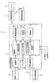
- FIG. 1 is a functional block diagram illustrating an embodiment.
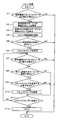
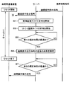
- FIG. 2 is a flowchart showing the reset process.
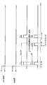
- FIG. 3 is a first timing chart.
- FIG. 4 is a second timing chart.
- FIG. 5 is a third timing chart.
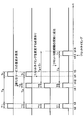
- FIG. 6 is a fourth timing chart.
- FIG. 7 is a fifth timing chart.
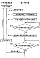
- FIG. 8 is a first sequence diagram.
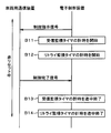
- FIG. 9 is a second sequence diagram.
- FIG. 10 is a third sequence diagram.
- FIG. 11 is a fourth sequence diagram.
- the communication system 1 is configured such that a vehicle communication device 2 mounted on a vehicle and a server 3 (corresponding to an external device) can communicate over a wide area.
- the vehicle communication device 2 includes a control unit 4 (corresponding to a reset target unit), a wireless communication unit 5 (corresponding to a reset target unit), a GNSS (Global Navigation Satellite System) receiving unit 6, a power supply unit 7, and a reset.
- Unit 8 in-car communication unit 9, and oscillation unit 10.
- the control unit 4 includes a microcomputer having a CPU (Central Processing Unit), a ROM (Read Only Memory), a RAM (Random Access Memory), and an I / O (Input / Output).
- the control unit 4 executes the computer program stored in the non-transitional tangible recording medium, thereby executing the software related to the control of the entire apparatus and controlling the overall operation of the vehicle communication apparatus 2.
- the wireless communication unit 5 executes software related to wireless communication by executing a computer program stored in a non-transitional tangible recording medium, and controls wireless communication of the vehicle communication device 2. Specifically, the wireless communication unit 5 performs wide-area wireless communication with the server 3 by transmitting and receiving communication radio waves to and from the wireless base station 11.
- the control unit 4 and the wireless communication unit 5 are composed of one chip.
- the GNSS receiving unit 6 extracts various parameters from the GNSS signal received from the satellite, calculates the current position using the extracted various parameters, and outputs the calculated current position to the control unit 4.
- the power supply unit 7 acquires power supplied from the vehicle battery 12 mounted on the vehicle as operating power.
- the reset unit 8 outputs a reset command to the control unit 4 when a reset request is input from the control unit 4.
- the control unit 4 outputs the reset command to the wireless communication unit 5 and resets (ie, initializes) the operation of the software.
- the wireless communication unit 5 resets the software operation.
- the resetting of the software operation in the control unit 4 and the wireless communication unit 5 means that the software is operated from the first procedure specified in advance (that is, restarted or restarted) regardless of whether the software is operating normally at that time. Refresh).
- the in-vehicle communication unit 9 is connected to an in-vehicle LAN 13 mounted on the vehicle, and via an electronic control device (ECU (Electronic Control Unit)) 14 (corresponding to an external device) mounted on the vehicle and the in-vehicle LAN 13. Perform data communication.
- the oscillation unit 10 generates a reference clock, and outputs the generated reference clock to the control unit 4.
- the control unit 4 includes a power source determination unit 4a, a reset execution unit 4b, a timing determination unit 4c, and a timing unit 4d. Each of these units 4a to 4d is realized by software.
- the power source determination unit 4a determines whether the vehicle power source is on or off based on an ACC signal indicating on / off of ACC (accessory) and an IG signal indicating on / off of IG (ignition). That is, the power supply determination unit 4a specifies that the vehicle power supply is turned on when the ACC signal is turned on or the IG signal is turned on, and specifies that the vehicle power supply is turned off when the ACC signal is turned off and the IG signal is turned off.
- the reset execution unit 4b causes the reset unit 8 to reset at least one of the software operation of the control unit 4 and the software operation of the wireless communication unit 5 at the reset timing determined by the timing determination unit 4c.
- the timing determination unit 4c determines, as a reset timing, a timing at which a predetermined period related to a service executed by software during a period in which the vehicle power is off and a reset period during which the operation of the software is not competed.
- the time measuring unit 4d uses the reference clock input from the oscillation unit 10 to measure time.
- the control unit 4 and the wireless communication unit 5 execute software by the power source unit 7 acquiring the power supplied from the vehicle battery 12 as the operating power regardless of whether the vehicle power source is on or off. That is, the control unit 4 and the wireless communication unit 5 are services such as emergency call, destination setting by data communication, and voice call when the vehicle power is on, that is, when the user is in general. When the vehicle power is off, that is, when the user is not in the vehicle, services such as theft tracking, remote engine start, remote door lock / unlock, etc. are performed.
- the service performed by the control unit 4 and the wireless communication unit 5 when the vehicle power is off is set in advance as a service (that is, a service immediately after parking) that is triggered by switching the vehicle power source from on to off.
- a service that is, a regular service during parking
- arrival at a specific date and time There is a service (that is, a regular service during parking) that is triggered by arrival at a specific date and time.
- the control unit 4 performs a service for transmitting a door lock forget notification signal indicating, for example, forgetting the door lock from the wireless communication unit 5 to the server 3 as a service immediately after parking.
- the server 3 receives the door lock forget notification signal from the vehicle communication device 2
- the server 3 transmits the door lock forget notification signal to the user's portable information terminal 15 set as a transmission destination in advance.
- the mobile information terminal 15 receives the door lock forget notification signal from the server 3
- the mobile information terminal 15 notifies the user that the door lock is forgotten.
- the portable information terminal 15 receives the door lock instruction signal (operation instruction signal, remote operation instruction). Signal) to the server 3.
- the server 3 When the server 3 receives the door lock instruction signal from the portable information terminal 15, the server 3 transmits the door lock instruction signal to the vehicle communication device 2.
- the control unit 4 receives the door lock instruction signal from the server 3 through the wireless communication unit 5, the control unit 4 outputs the door lock instruction signal from the in-vehicle communication unit 9 to a door lock ECU (not shown) to perform door lock control.
- control unit 4 provides a service for causing the server 3 to transmit a current position notification signal indicating the current position (that is, the parking position) calculated by the GNSS receiving unit 6 as a periodic service during parking. Do.
- the server 3 when receiving the current position notification signal from the vehicle communication device 2, the server 3 transmits the current position notification signal to the portable information terminal 15 set as a transmission destination in advance. Further, when the server 3 determines the possibility of vehicle theft using the history of the current position and determines that there is a possibility of vehicle theft, the server 3 sends a theft notification signal to the portable information terminal 15 set as a transmission destination in advance. Send.
- the portable information terminal 15 notifies the user of the current position of the vehicle. Further, when receiving the theft notification signal from the server 3, the portable information terminal 15 notifies the user of the possibility of the vehicle theft.
- the control unit 4 performs the reset process shown in FIG.
- the control unit 4 determines whether or not the vehicle power supply is switched from on to off (A1, first procedure). When it is determined that the vehicle power supply has not been switched from on to off (A1: NO), the control unit 4 ends the reset process and waits for the start of the next reset process. On the other hand, when the control unit 4 determines that the ACC signal is switched from on to off and the IG signal is switched from on to off and the vehicle power supply is switched from on to off (A1: YES), immediately after parking.
- the service implementation timing is specified (A2). For example, as described above, when the control unit 4 performs a service for transmitting a door lock forget notification signal as described above, the timing for transmitting the door lock forget notification signal is specified as the execution timing.
- control unit 4 identifies the implementation timing of the regular service during parking (A3). For example, if the control unit 4 performs a service for transmitting a current position notification signal as described above as a periodic service during parking, the control unit 4 identifies the timing for transmitting the current position notification signal as the execution timing.
- the control unit 4 searches for a resettable period corresponding to the sum of a preset setting period (for example, 1 hour) and a reset period in consideration of the specified service execution timing (A4).
- the setting period is a period that is set in advance in consideration of performing a service and performing another service related to the performed service or retrying the execution of the service.
- the reset period is a period from the start point to the end point (that is, from the start to the completion of the reset) when the operation of the software is reset.
- the control unit 4 determines the reset period after the set period starting from the end timing of the immediately preceding service in the successful search period (A6, second) procedure).
- the control unit 4 determines that the vehicle power supply is switched from on to off at the timing “t1”, the service immediately after parking or the periodic service during parking is performed. Assuming that “t2” is specified as the execution timing of. If the service execution period from the start point to the end point of service (that is, from the start to the end of the service) is “T1”, the control unit 4 starts immediately after “t3” that is the end point of the service execution period “T1”. A resettable period “Ta + Tr” corresponding to the sum of the set period “Ta” and the reset period “Tr” is searched.
- the control unit 4 determines that the resettable period can be secured immediately after “t3” and succeeds in searching for the resettable period. To do. Then, when the search for the resettable period is successful, the control unit 4 determines “t4” after the set period “Ta” as a reset timing, starting from “t3”. That is, the control unit 4 sets a period including the service implementation period “T1” and the set period “Ta” as a predetermined period “T1 + Ta” related to the service, and the predetermined period “T1 + Ta” and the reset period “Tr” do not compete with each other. The timing is determined as the reset timing.
- “t2” is used as the timing of performing the service immediately after parking or the regular service during parking. ”Is specified, and the implementation timing of the next service is specified.
- the control unit 4 searches for a resettable period immediately after “t3”, which is the end point of the service implementation period “T1”. However, since another service implementation period is specified after “t3”, the control unit 4 starts from “t3”. The period until the start point of another service implementation period is compared with the resettable period.
- the control is performed.
- the unit 4 determines that the period from “t3” to “t11” is longer than the resettable period. That is, similarly to FIG. 3, the control unit 4 determines that the resettable period can be secured immediately after “t3”, and succeeds in searching for the resettable period. Then, when the search for the resettable period is successful, the control unit 4 determines “t4” after the set period “Ta” as a reset timing, starting from “t3”.
- the control unit 4 determines that the period from “t3” that is the end point of the first service implementation period “T1” to “t21” that is the start point of the next service implementation period “T3” is relatively short. That is, unlike FIG. 3 and FIG. 4, the control unit 4 determines that the resettable period cannot be secured immediately after “t3”, and fails to search for the resettable period. If the search for the resettable period fails, the control unit 4 searches for the resettable period immediately after “t22” which is the end point of the next service implementation period “T3”.
- control unit 4 since the control unit 4 has not specified another service implementation period after “t22”, it is determined that the resettable period can be secured immediately after “t22”, and the search for the resettable period is successful. To do. Then, when the search for the resettable period is successful, the control unit 4 determines “t23” after the set period “Ta” as a reset timing, starting from “t22”. The control unit 4 sets a period including the service implementation period “T3” and the set period “Ta” as a predetermined period “T3 + Ta” related to the service, and sets a timing at which the predetermined period “T3 + Ta” and the reset period “Tr” do not compete with each other. Determined as reset timing. Although the case where two service implementation periods occur has been described above, the same applies to the case where three or more service implementation periods occur.
- the control unit 4 determines whether or not the vehicle power supply has been switched from OFF to ON (A7), and whether a request for a service to be newly implemented by the software has occurred. (A8, 4th procedure) and it is determined whether the reset timing has been reached (A11). Before determining that the reset timing has been reached, the control unit 4 determines that the ACC signal has been switched from OFF to ON or that the IG signal has been switched from OFF to ON and that the vehicle power supply has been switched from OFF to ON. Then (A7: YES), the reset process is terminated and the start of the next reset process is awaited. When the reset process is completed, the control unit 4 discards (that is, deletes) the reset timing determined at that time.
- the control unit 4 determines whether or not the reset timing determined at that time needs to be changed ( A9, fifth procedure).
- the service newly implemented by the software is a service different from any of the services immediately after parking and the regular services during parking.
- the control unit 4 determines that there is no need to change the reset timing (A9: NO)
- the control unit 4 maintains the reset timing without changing it.
- the control unit 4 changes the reset timing (A10, sixth procedure).
- a request for a service to be newly implemented by software is generated.
- the control unit 4 determines whether or not there is a conflict between a predetermined period related to a service newly implemented by the software and the already determined reset period, and whether or not the reset timing needs to be changed. Determine.
- the control unit 4 performs the service implementation period “T4” after “t5”. Is specified.
- control unit 4 determines that the predetermined period related to the service newly implemented by the software does not conflict with the already determined reset period, and determines that there is no need to change the reset timing. That is, the control unit 4 maintains the reset timing without changing it.
- the control unit 4 re-determines “t43” after the set period “Ta” as the reset timing, starting from “t42”. That is, the control unit 4 changes the reset timing.
- control unit 4 needs to change the reset timing according to the contents of the service as well as determine whether or not the predetermined period relating to the service newly implemented by the software and the already determined reset period conflict. It may be determined whether or not there is. That is, in the case where, for example, unlock control or door open control is performed as a service newly implemented by software, there is a high possibility that the user gets on immediately after that.
- the control unit 4 may change the reset timing by discarding the reset timing determined at that time when a request for a service that performs control with a high possibility of the user getting on immediately occurs.
- control unit 4 determines that the reset timing has been reached (A11: YES)
- the control unit 4 outputs a reset request to the reset unit 8, performs reset (A12, third procedure), and ends the reset process. That is, the control unit 4 receives a reset command from the reset unit 8, outputs the reset command to the wireless communication unit 5, and resets the operation of its own software. Further, the wireless communication unit 5 inputs a reset command from the control unit 4 and resets the operation of its own software.
- the control unit 4 determines, as the reset timing, a timing at which the software does not compete with the predetermined period related to the service and the reset period when the vehicle power is off. Then, when the reset timing is reached, the control unit 4 resets both its own software operation and the software operation of the wireless communication unit 5.
- the configuration in which both the software operation of the control unit 4 and the software operation of the wireless communication unit 5 are reset is exemplified, but a configuration in which any one of them is reset may be used. That is, when the reset unit 8 receives a reset command from the reset unit 8, the control unit 4 may output the reset command to the wireless communication unit 5 without resetting the operation of its own software. Further, when a reset command is input from the reset unit 8, the control unit 4 may reset the operation of its own software without outputting the reset command to the wireless communication unit 5.
- the server 3 transmits a remote operation instruction signal such as the door lock instruction signal described above.
- the server 3 determines that the portable information terminal 15 has received a remote operation instruction such as a door lock operation from the user and has received a remote operation instruction signal from the portable information terminal 15, the server 3 outputs the remote operation instruction signal. It transmits to the communication apparatus 2 for vehicles.
- the server 3 starts measuring the reception monitoring timer (B1), starts measuring the retry monitoring timer (B2), The remote control completion signal is awaited until the first specified time has elapsed from the time of transmission.
- the control unit 4 is not in the reset period and the wireless communication unit 5 is not in the reset period (that is, in the non-reset state), the remote operation instruction signal Is received by the wireless communication unit 5 and the remote operation instruction signal is successfully received.
- the electronic control device that is, a door lock ECU if the door lock operation is performed
- the remote operation signal as an object of remote operation (not shown) from the in-vehicle communication unit 9.
- the control unit 4 causes the wireless communication unit 5 to transmit a remote operation completion signal indicating the completion of the remote operation control to the server 3.
- the server 3 determines that the remote operation completion signal has been received before the first specified time has elapsed since the start of the reception monitoring timer, the server 3 transmits the remote operation completion signal to the portable information terminal 15 and receives the monitoring.
- the timer timing is terminated halfway (B3), and the retry monitoring timer timing is terminated halfway (B4).
- the remote operation instruction signal is transmitted from the wireless communication unit 5. It is not received and reception of the remote operation instruction signal fails. That is, the control unit 4 does not perform remote operation control and does not cause the remote communication completion signal to be transmitted from the wireless communication unit 5 to the server 3.
- the server 3 determines that the first specified time has elapsed without receiving the remote operation completion signal (B5: YES), the server 3 determines that the transmission of the remote operation signal has failed (that is, has not reached the vehicle communication device 2).
- the server 3 retries transmission of the remote operation instruction signal.
- the server 3 sets the second specified time longer than the reset period, and retries transmission of the remote operation instruction signal at a cycle longer than the reset period. That is, the server 3 retries transmission of the remote operation instruction signal during the reset period of the vehicle communication device 2 by setting the period of retrying transmission of the remote operation instruction signal to a period longer than the reset period.
- the electronic control device 14 sends the control instruction signal to the vehicle communication device.
- the timing at which the predetermined period related to the service and the reset period do not compete during the vehicle power-off period is determined as the reset timing, and the software operation of the control unit 4 and the software operation of the wireless communication unit 5 Is reset at the determined reset timing.
- the operation of the software can be reset without interfering with the service performed by the software while the vehicle power is off, and the operation of the software can be appropriately reset and stabilized.
- a predetermined period related to the newly generated service conflicts with the already determined reset period.
- the reset timing was redetermined. Therefore, even when a request for a service newly implemented by software occurs, the operation of the software can be appropriately reset and stabilized by re-determining the reset timing.
- the transmission of the remote operation instruction signal to the vehicle communication device 2 when the transmission of the remote operation instruction signal to the vehicle communication device 2 is retried, the transmission of the remote operation instruction signal is retried in a cycle longer than the reset period of the vehicle communication device 2. . Thereby, the situation where transmission of a remote operation instruction signal is retried during the reset period of vehicle communication device 2 can be avoided.
- the electronic control unit 14 when the transmission of the control instruction signal to the vehicle communication device 2 is retried, the transmission of the control instruction signal is retried at a cycle longer than the reset period of the vehicle communication device 2. . Thereby, the situation where transmission of a control instruction signal is retried during the reset period of vehicle communication device 2 can be avoided.
- the configuration of resetting the software operation of the control unit 4 and the wireless communication unit 5 is exemplified, but the configuration of resetting the software operation of the functional block different from the control unit 4 and the wireless communication unit 5 may be used. .
Landscapes
- Engineering & Computer Science (AREA)
- Theoretical Computer Science (AREA)
- Physics & Mathematics (AREA)
- General Engineering & Computer Science (AREA)
- General Physics & Mathematics (AREA)
- Quality & Reliability (AREA)
- Mechanical Engineering (AREA)
- Mobile Radio Communication Systems (AREA)
- Selective Calling Equipment (AREA)
- Telephone Function (AREA)
Abstract
Description
本開示の一側面の車両用通信装置は、車両電源がオン及びオフの何れでもソフトウェアを実行するリセット対象部と、前記リセット対象部のソフトウェアの動作をリセットするリセット部と、車両電源のオンオフを判定する電源判定部と、車両電源のオフが前記電源判定部により判定されると、その車両電源がオフの期間に、前記リセット対象部のソフトウェアの動作を予め決定されたリセットタイミングで前記リセット部によりリセットさせるリセット実行部と、を備える。
Claims (13)
- 車両電源がオン及びオフの何れでもソフトウェアを実行するリセット対象部(4,5)と、
前記リセット対象部のソフトウェアの動作をリセットするリセット部(8)と、
車両電源のオンオフを判定する電源判定部(4a)と、
車両電源のオフが前記電源判定部により判定されると、その車両電源がオフの期間に、前記リセット対象部のソフトウェアの動作を予め決定されたリセットタイミングで前記リセット部によりリセットさせるリセット実行部(4b)と、を備えた車両用通信装置(4)。 - 請求項1に記載した車両用通信装置において、
車両電源がオフの期間にソフトウェアが実施するサービスに係る所定期間とリセット期間とが競合しないタイミングをリセットタイミングとして決定するタイミング決定部(4c)を備え、
前記リセット実行部は、前記リセット対象部のソフトウェアの動作を前記タイミング決定部により決定されたリセットタイミングで前記リセット部によりリセットさせる車両用通信装置。 - 請求項1又は2に記載した車両用通信装置において、
前記タイミング決定部は、車両電源のオンからオフへの切り換えを契機とするサービスに係る前記所定期間と前記リセット期間とが競合しないタイミングを前記リセットタイミングとして決定する車両用通信装置。 - 請求項1から3の何れか一項に記載した車両用通信装置において、
前記タイミング決定部は、予め設定されている特定の日時への到達を契機とするサービスに係る前記所定期間と前記リセット期間とが競合しないタイミングを前記リセットタイミングとして決定する車両用通信装置。 - 請求項1から4の何れか一項に記載した車両用通信装置において、
前記タイミング決定部は、前記リセットタイミングを決定した後にソフトウェアが新たに実施するサービスの要求が発生し、その時点で決定しているリセットタイミングを変更する必要があると、その時点で決定しているリセットタイミングを変更する車両用通信装置。 - 請求項1から5の何れか一項に記載した車両用通信装置において、
前記リセット対象部は、装置全体の制御に係るソフトウェアを実行する制御部(4)及び無線通信に係るソフトウェアを実行する無線通信部(5)のうち少なくとも何れかを含む車両用通信装置。 - 車両電源がオン及びオフの何れでもソフトウェアを実行するリセット対象部(4,5)と、前記リセット対象部のソフトウェアの動作をリセットするリセット部(8)と、を備えた車両用通信装置(2)のマイクロコンピュータに、
車両電源がオフの期間を判定する第1の手順と、
リセットタイミングを決定する第2の手順と、
車両電源のオフを前記第1の手順により判定すると、その車両電源がオフの期間に、前記リセット対象部のソフトウェアの動作を前記第2の手順により決定したリセットタイミングで前記リセット部によりリセットさせる第3の手順と、を実行させるコンピュータプログラム。 - 請求項7に記載したコンピュータプログラムにおいて、
前記第2の手順は、車両電源がオフの期間にソフトウェアが実施するサービスに係る所定期間とリセット期間とが競合しないタイミングをリセットタイミングとして決定するコンピュータプログラム。 - 請求項8に記載したコンピュータプログラムにおいて、
前記リセットタイミングを決定した後にソフトウェアが新たに実施するサービスの要求が発生したか否かを判定する第4の手順と、
ソフトウェアが新たに実施するサービスの要求が発生したと前記第5の手順により判定すると、その時点で決定しているリセットタイミングを変更する必要があるか否かを判定する第5の手順と、
リセットタイミングを変更する必要があると前記第5の手順により判定すると、その時点で決定しているリセットタイミングを変更する第6の手順と、を実行させるコンピュータプログラム。 - 車両電源がオフの期間に、前記リセット対象部(4,5)のソフトウェアの動作を予め決定されたリセットタイミングでリセット部(8)によりリセットさせる車両通信装置(4)と、
動作指示信号を前記車両用通信装置に送信する外部装置(3,14)と、を備え、
前記外部装置は、車両電源がオフの期間に動作指示信号の前記車両用通信装置への送信をリトライする際には、リセット期間よりも長い周期で動作指示信号の前記車両用通信装置への送信をリトライする通信システム(1)。 - 請求項10に記載した通信システムにおいて、
前記外部装置は、前記動作指示信号として遠隔操作指示信号を前記車両用通信装置に送信するサーバ(3)を含む通信システム。 - 請求項10又は11に記載した通信システムにおいて、
前記外部装置は、前記動作指示信号として制御指示信号を前記車両用通信装置に送信する電子制御装置(14)を含む通信システム。 - 請求項7から9の何れか一項に記載したコンピュータプログラムを記憶する非一時的記憶媒体。
Priority Applications (3)
| Application Number | Priority Date | Filing Date | Title |
|---|---|---|---|
| CA2998604A CA2998604C (en) | 2015-09-15 | 2016-08-22 | Vehicle communication apparatus, program product and communication system |
| US15/758,006 US10296420B2 (en) | 2015-09-15 | 2016-08-22 | Vehicle communication apparatus, program product and communication system |
| CN201680052798.1A CN108027756B (zh) | 2015-09-15 | 2016-08-22 | 车辆用通信装置、记录有计算机程序的存储装置以及通信系统 |
Applications Claiming Priority (2)
| Application Number | Priority Date | Filing Date | Title |
|---|---|---|---|
| JP2015181807A JP6237737B2 (ja) | 2015-09-15 | 2015-09-15 | 車両用通信装置、コンピュータプログラム及び通信システム |
| JP2015-181807 | 2015-09-15 |
Publications (1)
| Publication Number | Publication Date |
|---|---|
| WO2017047324A1 true WO2017047324A1 (ja) | 2017-03-23 |
Family
ID=58288825
Family Applications (1)
| Application Number | Title | Priority Date | Filing Date |
|---|---|---|---|
| PCT/JP2016/074317 Ceased WO2017047324A1 (ja) | 2015-09-15 | 2016-08-22 | 車両用通信装置、コンピュータプログラム及び通信システム |
Country Status (5)
| Country | Link |
|---|---|
| US (1) | US10296420B2 (ja) |
| JP (1) | JP6237737B2 (ja) |
| CN (1) | CN108027756B (ja) |
| CA (1) | CA2998604C (ja) |
| WO (1) | WO2017047324A1 (ja) |
Families Citing this family (3)
| Publication number | Priority date | Publication date | Assignee | Title |
|---|---|---|---|---|
| JP7115330B2 (ja) * | 2019-01-16 | 2022-08-09 | トヨタ自動車株式会社 | 車載システム、無線通信装置、及び制御方法 |
| DE102019204941A1 (de) * | 2019-04-05 | 2020-10-08 | Robert Bosch Gmbh | System zum sicheren teleoperierten Fahren |
| WO2022092264A1 (ja) * | 2020-10-30 | 2022-05-05 | 株式会社 ミックウェア | 情報処理システム、処理装置及び情報処理方法 |
Citations (4)
| Publication number | Priority date | Publication date | Assignee | Title |
|---|---|---|---|---|
| JP2005309495A (ja) * | 2004-04-16 | 2005-11-04 | Eastman Kodak Co | 電子装置、電子装置の制御方法及び電子装置の制御プログラム |
| JP2009128313A (ja) * | 2007-11-27 | 2009-06-11 | Hitachi Ltd | カーナビゲーション装置、制御方法、プログラムおよび制御装置 |
| JP2012187710A (ja) * | 2011-03-08 | 2012-10-04 | Canon Inc | 画像形成装置、画像形成装置の制御方法及びプログラム |
| WO2014055198A1 (en) * | 2012-10-04 | 2014-04-10 | Qualcomm Incorporated | Method for preemptively restarting software in a multisubsystem mobile communication device to increase mean time between failures |
Family Cites Families (11)
| Publication number | Priority date | Publication date | Assignee | Title |
|---|---|---|---|---|
| US5742800A (en) * | 1995-10-31 | 1998-04-21 | Seagate Technology, Inc. | Disc drive reset using power valid, clocks valid and delay criteria |
| JP4151534B2 (ja) | 2003-09-18 | 2008-09-17 | 株式会社デンソー | 車両用通信装置、及び、データ通信システム |
| JP2007316855A (ja) * | 2006-05-24 | 2007-12-06 | Toshiba Corp | 電子機器及び電子機器の再起動方法 |
| JP4818189B2 (ja) * | 2007-04-19 | 2011-11-16 | キヤノン株式会社 | 撮像装置及びその制御方法 |
| US20130145401A1 (en) * | 2011-11-16 | 2013-06-06 | Flextronics Ap, Llc | Music streaming |
| CN102163071B (zh) * | 2011-01-20 | 2013-09-11 | 海能达通信股份有限公司 | 一种控制电路及其复位时的电源控制方法 |
| US8949823B2 (en) * | 2011-11-16 | 2015-02-03 | Flextronics Ap, Llc | On board vehicle installation supervisor |
| JP5729767B2 (ja) | 2012-01-06 | 2015-06-03 | Kddi株式会社 | スマートフォンの動作安定化方法、動作安定化プログラム及び動作安定化装置。 |
| EP2823367A4 (en) | 2012-03-07 | 2016-06-29 | Int Truck Intellectual Prop Co | ON-BOARD MONITORING FOR A VEHICLE |
| CN103631476B (zh) * | 2012-08-29 | 2017-03-01 | 瑞昱半导体股份有限公司 | 电子装置的模式切换方法与相关的电子装置 |
| CN204202675U (zh) * | 2014-09-16 | 2015-03-11 | 潍坊奥博仪表科技发展有限公司 | 一种aobo-dl断电记录仪 |
-
2015
- 2015-09-15 JP JP2015181807A patent/JP6237737B2/ja not_active Expired - Fee Related
-
2016
- 2016-08-22 CN CN201680052798.1A patent/CN108027756B/zh not_active Expired - Fee Related
- 2016-08-22 CA CA2998604A patent/CA2998604C/en active Active
- 2016-08-22 US US15/758,006 patent/US10296420B2/en active Active
- 2016-08-22 WO PCT/JP2016/074317 patent/WO2017047324A1/ja not_active Ceased
Patent Citations (4)
| Publication number | Priority date | Publication date | Assignee | Title |
|---|---|---|---|---|
| JP2005309495A (ja) * | 2004-04-16 | 2005-11-04 | Eastman Kodak Co | 電子装置、電子装置の制御方法及び電子装置の制御プログラム |
| JP2009128313A (ja) * | 2007-11-27 | 2009-06-11 | Hitachi Ltd | カーナビゲーション装置、制御方法、プログラムおよび制御装置 |
| JP2012187710A (ja) * | 2011-03-08 | 2012-10-04 | Canon Inc | 画像形成装置、画像形成装置の制御方法及びプログラム |
| WO2014055198A1 (en) * | 2012-10-04 | 2014-04-10 | Qualcomm Incorporated | Method for preemptively restarting software in a multisubsystem mobile communication device to increase mean time between failures |
Also Published As
| Publication number | Publication date |
|---|---|
| CN108027756A (zh) | 2018-05-11 |
| US20180253356A1 (en) | 2018-09-06 |
| CA2998604C (en) | 2021-06-15 |
| US10296420B2 (en) | 2019-05-21 |
| CN108027756B (zh) | 2021-12-10 |
| JP6237737B2 (ja) | 2017-11-29 |
| JP2017058837A (ja) | 2017-03-23 |
| CA2998604A1 (en) | 2017-03-23 |
Similar Documents
| Publication | Publication Date | Title |
|---|---|---|
| JP6428580B2 (ja) | ソフトウェア更新装置 | |
| US11997562B2 (en) | Tracking proximities of devices and/or objects | |
| JP6237737B2 (ja) | 車両用通信装置、コンピュータプログラム及び通信システム | |
| JP2009020730A (ja) | 車載通信端末 | |
| CN112416641B (zh) | 主从架构中被控端节点重启检测方法及主控端节点 | |
| WO2013089210A1 (ja) | 制御装置及び処理監視方法 | |
| US20170234989A1 (en) | Quick positioning system and vehicle-mounted system | |
| CN119078703A (zh) | 车辆控制方法、装置、电子设备及车辆 | |
| CN115842995B (zh) | 信息处理装置以及信息处理方法 | |
| JP4508013B2 (ja) | 車載無線通信機器 | |
| JP6140660B2 (ja) | 端末装置、位置取得方法、及び、位置取得制御用プログラム | |
| WO2025020646A1 (zh) | 一种终端设备的飞行模式控制方法、终端设备及相关设备 | |
| US11963090B2 (en) | Communication control device, terminal device, communication control method, and control program | |
| CN116347340B (zh) | 汽车钥匙、移动终端以及查找汽车钥匙的方法 | |
| CN113810449B (zh) | 一种保持设备在线的控制方法、装置、设备及存储介质 | |
| JP6988591B2 (ja) | 電子装置及びその制御方法 | |
| CN112788093A (zh) | 车辆管理服务器、车辆管理方法以及非暂时性存储介质 | |
| US10116171B2 (en) | Power receiving apparatus and method for preventing unfair use | |
| US11553326B2 (en) | Communication device and communication method for transmitting notifications to communicate with first and second softwares and to cause second software to be on standby and to cancel being on standby | |
| US20250260594A1 (en) | Information processing device | |
| JP2019011020A (ja) | 報知システム | |
| JP2000076598A (ja) | 車両運行管理システム用の端末装置 | |
| TW202501420A (zh) | 智慧鑰匙遺失提醒方法及非暫態電腦可讀取媒體 | |
| CN115915317A (zh) | 车辆的网络切换方法、装置、设备及存储介质 | |
| CN113676588A (zh) | 发出求助请求的方法、装置、计算机设备及存储介质 |
Legal Events
| Date | Code | Title | Description |
|---|---|---|---|
| 121 | Ep: the epo has been informed by wipo that ep was designated in this application |
Ref document number: 16846195 Country of ref document: EP Kind code of ref document: A1 |
|
| WWE | Wipo information: entry into national phase |
Ref document number: 15758006 Country of ref document: US |
|
| ENP | Entry into the national phase |
Ref document number: 2998604 Country of ref document: CA |
|
| NENP | Non-entry into the national phase |
Ref country code: DE |
|
| 122 | Ep: pct application non-entry in european phase |
Ref document number: 16846195 Country of ref document: EP Kind code of ref document: A1 |