WO2017043157A1 - 光ファイバプローブ、光ファイバ計測装置及びクリアランス制御システム - Google Patents
光ファイバプローブ、光ファイバ計測装置及びクリアランス制御システム Download PDFInfo
- Publication number
- WO2017043157A1 WO2017043157A1 PCT/JP2016/069278 JP2016069278W WO2017043157A1 WO 2017043157 A1 WO2017043157 A1 WO 2017043157A1 JP 2016069278 W JP2016069278 W JP 2016069278W WO 2017043157 A1 WO2017043157 A1 WO 2017043157A1
- Authority
- WO
- WIPO (PCT)
- Prior art keywords
- optical fiber
- diameter portion
- light
- probe
- internal space
- Prior art date
- Legal status (The legal status is an assumption and is not a legal conclusion. Google has not performed a legal analysis and makes no representation as to the accuracy of the status listed.)
- Ceased
Links
Images


Classifications
-
- F—MECHANICAL ENGINEERING; LIGHTING; HEATING; WEAPONS; BLASTING
- F01—MACHINES OR ENGINES IN GENERAL; ENGINE PLANTS IN GENERAL; STEAM ENGINES
- F01D—NON-POSITIVE DISPLACEMENT MACHINES OR ENGINES, e.g. STEAM TURBINES
- F01D11/00—Preventing or minimising internal leakage of working-fluid, e.g. between stages
- F01D11/08—Preventing or minimising internal leakage of working-fluid, e.g. between stages for sealing space between rotor blade tips and stator
- F01D11/14—Adjusting or regulating tip-clearance, i.e. distance between rotor-blade tips and stator casing
- F01D11/20—Actively adjusting tip-clearance
- F01D11/22—Actively adjusting tip-clearance by mechanically actuating the stator or rotor components, e.g. moving shroud sections relative to the rotor
-
- F—MECHANICAL ENGINEERING; LIGHTING; HEATING; WEAPONS; BLASTING
- F01—MACHINES OR ENGINES IN GENERAL; ENGINE PLANTS IN GENERAL; STEAM ENGINES
- F01D—NON-POSITIVE DISPLACEMENT MACHINES OR ENGINES, e.g. STEAM TURBINES
- F01D11/00—Preventing or minimising internal leakage of working-fluid, e.g. between stages
- F01D11/08—Preventing or minimising internal leakage of working-fluid, e.g. between stages for sealing space between rotor blade tips and stator
- F01D11/14—Adjusting or regulating tip-clearance, i.e. distance between rotor-blade tips and stator casing
- F01D11/20—Actively adjusting tip-clearance
- F01D11/24—Actively adjusting tip-clearance by selectively cooling-heating stator or rotor components
-
- F—MECHANICAL ENGINEERING; LIGHTING; HEATING; WEAPONS; BLASTING
- F01—MACHINES OR ENGINES IN GENERAL; ENGINE PLANTS IN GENERAL; STEAM ENGINES
- F01D—NON-POSITIVE DISPLACEMENT MACHINES OR ENGINES, e.g. STEAM TURBINES
- F01D21/00—Shutting-down of machines or engines, e.g. in emergency; Regulating, controlling, or safety means not otherwise provided for
- F01D21/003—Arrangements for testing or measuring
-
- F—MECHANICAL ENGINEERING; LIGHTING; HEATING; WEAPONS; BLASTING
- F01—MACHINES OR ENGINES IN GENERAL; ENGINE PLANTS IN GENERAL; STEAM ENGINES
- F01D—NON-POSITIVE DISPLACEMENT MACHINES OR ENGINES, e.g. STEAM TURBINES
- F01D25/00—Component parts, details, or accessories, not provided for in, or of interest apart from, other groups
-
- F—MECHANICAL ENGINEERING; LIGHTING; HEATING; WEAPONS; BLASTING
- F02—COMBUSTION ENGINES; HOT-GAS OR COMBUSTION-PRODUCT ENGINE PLANTS
- F02C—GAS-TURBINE PLANTS; AIR INTAKES FOR JET-PROPULSION PLANTS; CONTROLLING FUEL SUPPLY IN AIR-BREATHING JET-PROPULSION PLANTS
- F02C7/00—Features, components parts, details or accessories, not provided for in, or of interest apart form groups F02C1/00 - F02C6/00; Air intakes for jet-propulsion plants
- F02C7/28—Arrangement of seals
-
- G—PHYSICS
- G01—MEASURING; TESTING
- G01B—MEASURING LENGTH, THICKNESS OR SIMILAR LINEAR DIMENSIONS; MEASURING ANGLES; MEASURING AREAS; MEASURING IRREGULARITIES OF SURFACES OR CONTOURS
- G01B11/00—Measuring arrangements characterised by the use of optical techniques
- G01B11/14—Measuring arrangements characterised by the use of optical techniques for measuring distance or clearance between spaced objects or spaced apertures
-
- F—MECHANICAL ENGINEERING; LIGHTING; HEATING; WEAPONS; BLASTING
- F05—INDEXING SCHEMES RELATING TO ENGINES OR PUMPS IN VARIOUS SUBCLASSES OF CLASSES F01-F04
- F05D—INDEXING SCHEME FOR ASPECTS RELATING TO NON-POSITIVE-DISPLACEMENT MACHINES OR ENGINES, GAS-TURBINES OR JET-PROPULSION PLANTS
- F05D2220/00—Application
- F05D2220/30—Application in turbines
- F05D2220/31—Application in turbines in steam turbines
-
- F—MECHANICAL ENGINEERING; LIGHTING; HEATING; WEAPONS; BLASTING
- F05—INDEXING SCHEMES RELATING TO ENGINES OR PUMPS IN VARIOUS SUBCLASSES OF CLASSES F01-F04
- F05D—INDEXING SCHEME FOR ASPECTS RELATING TO NON-POSITIVE-DISPLACEMENT MACHINES OR ENGINES, GAS-TURBINES OR JET-PROPULSION PLANTS
- F05D2220/00—Application
- F05D2220/30—Application in turbines
- F05D2220/32—Application in turbines in gas turbines
-
- F—MECHANICAL ENGINEERING; LIGHTING; HEATING; WEAPONS; BLASTING
- F05—INDEXING SCHEMES RELATING TO ENGINES OR PUMPS IN VARIOUS SUBCLASSES OF CLASSES F01-F04
- F05D—INDEXING SCHEME FOR ASPECTS RELATING TO NON-POSITIVE-DISPLACEMENT MACHINES OR ENGINES, GAS-TURBINES OR JET-PROPULSION PLANTS
- F05D2270/00—Control
- F05D2270/80—Devices generating input signals, e.g. transducers, sensors, cameras or strain gauges
- F05D2270/804—Optical devices
Definitions
- the present invention relates to an optical fiber probe which is a probe using an optical fiber, an optical fiber measuring device, and a clearance control system.
- a reflection probe having a 6 ⁇ 1 fiber configuration is known as an optical fiber probe (see, for example, Patent Document 1).
- This reflection probe has a center fiber and six coaxial fibers.
- an optical fiber probe such as a reflection probe may be provided in a turbine such as a steam turbine or a gas turbine, for example.
- the optical fiber probe is exposed to a high temperature / high pressure environment.
- the optical fiber may sink from the surface to be detected, or a part of the ceramic sealing material used to fix the optical fiber may be lost. There is sex.
- the position or shape of the optical fiber changes, and the detection accuracy using the optical fiber probe may decrease.
- an object of the present invention is to provide an optical fiber probe, an optical fiber measuring device, and a clearance control system that can suppress a change in optical fiber caused by an external environment and suppress a decrease in detection accuracy. .
- the optical fiber probe of the present invention is a probe main body having a detection surface provided on the outer surface and an internal space provided inside, and is housed in the internal space, and a distal end portion is on the detection surface side of the probe main body.
- the probe body has a bottom surface provided on the opposite side of the detected surface in the internal space, and a through-hole communicating between the detected surface and the bottom surface
- the thin-diameter portion is inserted through the through hole, the large-diameter portion is disposed in a state where the tip portion is in contact with the bottom surface and is bent in the internal space, and the position restricting member is Provided in contact with the rear end of the diameter portion In a state of bending the said large diameter portion, characterized in that for regulating the position of the optical fiber.
- the large diameter portion can be pressed against the bottom surface side of the internal space by bending the large diameter portion of the optical fiber. For this reason, even when the external environment is a high-temperature / high-pressure environment, it is possible to suppress the narrow diameter portion of the optical fiber from sinking from the detection surface of the probe body. Moreover, since the sealing material for fixing the optical fiber to the probe body can be omitted, the sealing material is not damaged. Therefore, since the change of the optical fiber caused by the external environment can be suppressed, a decrease in detection accuracy can be suppressed.
- Another optical fiber probe of the present invention includes a probe main body having a detection surface provided on the outer surface and an internal space provided in the inside, and is stored in the internal space, and a tip portion is the detection surface of the probe main body.
- An optical fiber disposed on the side of the probe, a position regulating member attached to the probe main body, and an elastic member that presses the optical fiber toward the detected surface.
- the optical fiber has a small diameter on the distal end side.
- the position regulating member is arranged in front Provided with a gap with respect to the rear end of the large-diameter portion, the elastic member may be provided in the gap between the position restricting member and the rear end portion of the large diameter portion.
- the optical fiber can be pressed toward the detection surface side by the elastic member.
- the diameter portion can be pressed against the bottom surface side of the internal space. For this reason, even when the external environment is a high-temperature / high-pressure environment, it is possible to suppress the narrow diameter portion of the optical fiber from sinking from the detection surface of the probe body.
- the sealing material for fixing the optical fiber to the probe body can be omitted, the sealing material is not damaged. Therefore, since the change of the optical fiber caused by the external environment can be suppressed, a decrease in detection accuracy can be suppressed.
- the optical fiber includes a core that is a central portion and a clad provided around the core, and the core has a diameter that is the same in the large diameter portion and the small diameter portion.
- the core In the clad, it is preferable that an outer diameter of the large-diameter portion is larger than that of the small-diameter portion.
- the outer diameter of the clad since the outer diameter of the clad only needs to be increased in the large diameter portion without changing the core diameter, the interface between the core and the clad can be maintained in a uniform state.
- an optical window that is inserted into the detected surface side of the through hole.
- the outside of the probe main body and the internal space of the probe main body can be partitioned by the optical window. For this reason, since the optical fiber is not exposed to the outside of the probe body and can be stored in the internal space, the optical fiber can be prevented from being exposed to the external environment.
- the optical window has a cylindrical shape that is long in the axial direction, the axial direction is the insertion direction of the through hole, and the outer peripheral surface of the optical window is plated.
- Another optical fiber probe of the present invention includes a probe main body having a detection surface provided on the outer surface and an internal space provided in the inside, and is stored in the internal space, and a tip portion is the detection surface of the probe main body.
- the outside of the probe main body and the internal space of the probe main body can be partitioned by the optical window. For this reason, since the optical fiber is not exposed to the outside of the probe body and can be stored in the internal space, the optical fiber can be prevented from being exposed to the external environment. For this reason, even when the external environment is a high temperature / high pressure environment, the tip of the optical fiber can be prevented from being depressed from the detection surface of the probe body. Moreover, since the sealing material for fixing the optical fiber to the probe body can be omitted, the sealing material is not damaged. Therefore, since the change of the optical fiber caused by the external environment can be suppressed, a decrease in detection accuracy can be suppressed.
- An optical fiber measuring device of the present invention includes the above-described optical fiber probe, a light emitting unit that emits light toward the optical fiber probe, a light receiving unit that receives light incident from the optical fiber probe, and the light emitting unit. And a measurement control unit that performs signal processing on the light emission signal to the light reception signal and the light reception signal from the light reception unit.
- the optical fiber is associated with a plurality of light transmitting fibers for emitting light from the detection surface and a plurality of the light transmission fibers, and receives light incident on the detection surface.
- a plurality of light receiving fibers, and the light emitting unit varies the color of light emitted from the plurality of light transmitting fibers, and the light receiving unit selects light of a plurality of different colors. It is preferable to have a plurality of filters.
- the clearance control system is a clearance control system that adjusts the clearance of a turbine including a casing and a moving blade that is provided to face the casing with a predetermined clearance therebetween. And the optical fiber measurement device that measures the clearance based on the received light signal and the clearance adjustment control for adjusting the clearance based on the clearance measured by the optical fiber measurement device.
- a turbine control unit A turbine control unit.
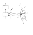
- FIG. 1 is a schematic configuration diagram relating to a clearance control system according to the first embodiment.
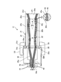
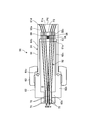
- FIG. 2 is a cross-sectional view schematically showing the optical fiber probe according to the first embodiment.
- FIG. 3 is an explanatory diagram relating to a clearance calculation method.
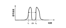
- FIG. 4 is a graph relating to the signal intensity of the received light signal detected using the optical fiber probe.
- FIG. 5 is a cross-sectional view schematically showing an optical fiber probe according to the first modification of the first embodiment.
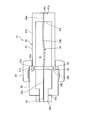
- FIG. 6 is a cross-sectional view schematically showing the optical fiber probe according to the second embodiment.
- FIG. 7 is a cross-sectional view schematically showing an optical fiber probe according to the second modification of the second embodiment.
- FIG. 8 is a cross-sectional view schematically showing the optical fiber probe according to the third embodiment.
- FIG. 9 is a schematic configuration diagram schematically illustrating the optical fiber measurement device according to the fourth embodiment.
- FIG. 1 is a schematic configuration diagram relating to a clearance control system according to the first embodiment.
- FIG. 2 is a cross-sectional view schematically showing the optical fiber probe according to the first embodiment.
- FIG. 3 is an explanatory diagram relating to a clearance calculation method.
- FIG. 4 is a graph relating to the signal intensity of the received light signal detected using the optical fiber probe.
- the clearance control system 1 measures the clearance d formed between the casing 5 and the moving blade 6 of the turbine 3, and adjusts the clearance d based on the measurement result.
- the turbine 3 will be described prior to the description of the clearance control system 1.
- the turbine 3 is a turbo machine including a steam turbine or a gas turbine.
- the turbine 3 includes a plurality of moving blades 6 provided on a rotor (not shown) serving as a rotating shaft, and a casing 5 provided around the plurality of moving blades 6.
- the plurality of moving blades 6 are attached to the rotor and are arranged side by side with a predetermined interval in the circumferential direction of the rotor.
- the casing 5 is provided to face the moving blades 6 provided side by side in the circumferential direction, and is formed in an annular shape.
- the casing 5 is provided to face the plurality of moving blades 6 with a predetermined clearance d.
- the casing 5 has a configuration including, for example, an inner casing and an outer casing provided outside the inner casing.
- the clearance control system 1 includes a turbine control unit 8 and an optical fiber measuring device 10, and the optical fiber measuring device 10 measures a clearance d.
- the turbine control unit 8 executes clearance adjustment control for adjusting the clearance d based on the clearance d measured by the optical fiber measuring device 10.
- the clearance d includes a clearance (so-called chip clearance) C in the radial direction of the rotor and a clearance d in the axial direction of the rotor.
- FIG. 1 shows the clearance d in the radial direction of the rotor.
- the turbine control unit 8 adjusts the clearance d, for example, by controlling an actuator that moves the casing 5 including the inner casing and the outer casing up and down as clearance adjustment control in the radial direction of the rotor. Further, the turbine control unit 8 adjusts the clearance d by controlling an actuator that moves the rotor up and down, for example. Further, the turbine control unit 8 adjusts the clearance d by controlling the temperature of the casing 5 and adjusting the thermal elongation of the casing 5, for example.
- the turbine control unit 8 adjusts the clearance d by controlling an actuator that moves the casing 5 including the inner casing and the outer casing in the axial direction as clearance adjustment control in the axial direction of the rotor, for example. . Further, the turbine control unit 8 adjusts the clearance d by controlling an actuator that moves the rotor in the axial direction, for example.
- the optical fiber measurement device 10 measures a clearance d between the casing 5 and the moving blade 6 and includes an optical fiber probe 11, a light emitting unit 12, a light receiving unit 13, and a measurement control unit 14. Yes.
- the optical fiber probe 11 is attached to the casing 5, and the detected surface P1 is disposed so as to face the moving blade 6 in the radial direction of the rotor. For this reason, the optical fiber probe 11 is exposed to a high temperature / high pressure external environment between the casing 5 and the moving blade 6.
- the optical fiber probe 11 includes a probe main body 21, a plurality of optical fibers 22, and a position regulating member 23.
- the probe main body 21 fastens the front end side case 31 on the detected surface P1 side, the rear end side case 32 provided on the rear end side of the front end side case 31, and the front end side case 31 and the rear end side case 32.
- a nut 33 is included, and a hollow internal space S is formed therein.
- the front end side case 31 has a bottom plate portion 31a, a cylindrical portion 31b, and a flange portion 31c, and is formed in a bottomed cylindrical shape.
- the outer surface becomes the to-be-detected surface P1
- the inner surface becomes the bottom face P2.
- a plurality of through holes 31d are formed in the bottom plate portion 31a in the thickness direction in which the detected surface P1 and the bottom surface P2 face each other.
- the through holes 31d are formed outside the probe main body 21 and the internal space S of the probe main body 21. And communicate with.
- the plurality of through holes 31d are close to one side in the radial direction to form a plurality of groups of through holes 31d, and close to the other side in the radial direction to form a plurality of other groups of through holes 31d.
- the penetration direction of one group of through holes 31d and the penetration direction of the other group of through holes 31d are formed to form a predetermined angle ⁇ .
- the cylindrical portion 31b is provided with a bottom plate portion 31a on the front end side and a flange portion 31c on the rear end side.
- the flange portion 31c is formed to protrude outward in the radial direction of the cylindrical portion 31b.
- the flange portion 31c functions as a stopper for the nut 33 to be fastened.
- the housing case 31e is formed in the distal end side case 31 over the entire circumference on the inner peripheral surface side of the flange portion 31c, and the position regulating member 23 is housed in the housing groove 31e.
- the rear end side case 32 has a bottom plate portion 32a and a cylindrical portion 32b, and is formed in a bottomed cylindrical shape.
- An insertion hole 32c through which the plurality of optical fibers 22 are inserted is formed in the bottom plate portion 32a.
- the cylindrical portion 32b is provided with a bottom plate portion 32a on the rear end side, and the flange portion 31c of the front end side case 31 abuts on the front end side.
- a male screw to which the nut 33 is fastened is formed on the outer peripheral surface on the distal end side of the cylindrical portion 32b.
- a pin 35 is provided between the front end side case 31 and the rear end side case 32, and the pin 35 regulates the positions of the front end side case 31 and the rear end side case 32 in the circumferential direction.
- the pin 35 restricts the front end side case 31 and the rear end side case 32 from being rotated when a nut 33 described later is fastened.
- the nut 33 is formed in an annular shape, and has an internal thread on the inner peripheral surface on one side in the axial direction and a protruding portion 33a that protrudes from the inner peripheral surface on the other side in the axial direction.
- the nut 33 is inserted from the front end side case 31, and the female screw of the nut 33 and the male screw of the rear end side case 32 are fastened. Further, the position of the nut 33 is regulated by the protruding portion 33 a coming into contact with the flange portion 31 c of the distal end side case 31.
- the plurality of optical fibers 22 are stored in the internal space S of the probe main body 21, and have a plurality of light transmitting fibers 41 and a plurality of light receiving fibers 42. Specifically, two light transmission fibers 41 are provided, and one light transmission fiber 41 is arranged close to one side (the upper side in FIG. 2) in the hollow internal space S, and the other The light transmission fiber 41 is arranged close to the other side (the lower side in FIG. 2).
- a plurality of light receiving fibers 42 are concentrically arranged with one light transmitting fiber 41 as a center, and similarly, a plurality of light receiving fibers 42 are concentrically arranged with the other light transmitting fiber 41 as a center.
- the plurality of optical fibers 22 are divided into a plurality of optical fibers 22 as a group and a plurality of optical fibers 22 as another group.
- each optical fiber 22 includes a narrow diameter portion 22a having a small diameter and a large diameter portion 22b having a large diameter.
- the small diameter portion 22a is provided at the distal end portion of the optical fiber 22 on the detected surface P1 side.
- the large diameter portion 22b is provided on the rear end side of the small diameter portion 22b, and the thin diameter portion 22a is provided on the rear end side of the large diameter portion 22b. That is, the large diameter part 22b is provided between the two small diameter parts 22a.
- the optical fiber 22 has a core 45 serving as a central portion and a clad 46 provided around the core 45, and the core 45 has the same diameter over the entire length of the optical fiber 22.
- the diameter of the core 45 in the small diameter part 22a and the large diameter part 22b of the optical fiber 22 is the same diameter.
- the clad 46 has a larger outer diameter at the large diameter portion 22b than at the small diameter portion 22a.
- the position restricting member 23 is formed in a disk shape, and is housed in the housing groove 31e of the distal end side case 31, thereby dividing the internal space S of the probe main body 21 into two.
- the position restricting member 23 is formed with a plurality of insertion holes 23a through which the small diameter portions 22a of the plurality of optical fibers 22 are inserted.
- the plurality of insertion holes 23a are formed to penetrate through the plurality of optical fibers 22 that form a group, and are formed to penetrate through the plurality of optical fibers 22 that form another group.
- the small diameter portion 22 a on the front end side is inserted into the through hole 31 d of the probe main body 21, and the small diameter portion 22 a on the rear end side is inserted into the insertion hole 23 a of the position regulating member 23.
- the optical fiber 22 is arranged in a state where the large diameter portion 22b is bent in the internal space S between the bottom surface P2 and the position regulating member 23. That is, the large diameter portion 22 b is formed longer than the length between the bottom surface P ⁇ b> 2 of the probe main body 21 and the position regulating member 23.
- the large diameter part 22b is arrange
- the light emitting unit 12 is connected to each of the two light transmission fibers 41 of the optical fiber probe 11 and emits light based on the light emission signal of the measurement control unit 14.
- the light emitted from the light transmission fiber 41 is applied to the moving blade 6, and the reflected light reflected from the moving blade 6 is incident on the detection surface P ⁇ b> 1 of the probe main body 21.
- the light receiving unit 13 is connected to the light receiving fiber 42 of the optical fiber probe 11, receives the reflected light incident from the detection surface P 1 of the probe main body 21, and outputs a light reception signal to the measurement control unit 14.
- the measurement control unit 14 is connected to the light emitting unit 12 and the light receiving unit 13, respectively, and outputs a light emission signal toward the light emitting unit 12 and receives a light receiving signal output from the light receiving unit 13.
- the measurement control unit 14 is connected to the turbine control unit 8, performs signal processing on the light emission signal and the light reception signal, measures the clearance d, and outputs the measured clearance d to the turbine control unit 8.
- the measurement control unit 14 calculates the clearance d based on the calculation formula shown in the following formula (1).
- the angle ⁇ is an angle formed by the light guide directions of the two lights emitted from the two light transmitting fibers 41, that is, the through direction of the group of through holes 31d and the other group of through holes 31d.
- This angle ⁇ is a known angle.
- the distance l is the length between AB, that is, the distance between the two light transmitting fibers 41, and is a known distance.
- the circumferential length 2 ⁇ R is a circumferential length on the outer circumference of the plurality of moving blades 6, and is a known circumferential length.
- Time T is a time taken for one rotation (one rotation), and is a time obtained based on the rotational speed of the rotor.
- “2 ⁇ R / T” is the peripheral speed at the outer periphery of the plurality of moving blades 6.
- the time ⁇ t is the time for the moving blade 6 to pass between the two light transmission fibers 41 and is obtained based on the light reception signal.
- the measurement control unit 14 acquires the light reception signal shown in FIG. 4 as the light reception signal.
- the horizontal axis represents time
- the vertical axis represents signal intensity.
- two signal peaks are detected in the received light signal.
- Two signal peaks are obtained by the two lights emitted from the two light transmission fibers 41.
- the measurement control part 14 acquires the time from one signal peak to the other signal peak as time (DELTA) t.
- the measurement control unit 14 calculates the clearance d based on the calculation formula shown in the above formula (1).
- the large-diameter portion 22b can be pressed against the bottom surface P2 side of the internal space S by bending the large-diameter portion 22b of the optical fiber 22 and disposing it in the internal space S. it can. For this reason, even when the external environment is a high temperature / high pressure environment, it is possible to suppress the narrow diameter portion 22a of the optical fiber 22 from being depressed from the detection surface P1 of the probe main body 21. Moreover, since the sealing material for fixing the optical fiber 22 to the probe body 21 can be omitted, the sealing material is not damaged. Therefore, since the change of the optical fiber 22 caused by the external environment can be suppressed, a decrease in detection accuracy can be suppressed.
- the diameter of the core 45 of the optical fiber 22 can be the same in the small diameter portion 22a and the large diameter portion 22b, so that the interface between the core 45 and the clad 46 is uniform. Can be maintained. Further, if the outer diameter of the clad 46 is increased, the large diameter portion 22b can be easily formed.
- the optical fiber measuring device 10 is used.
- the clearance d can be accurately measured.
- the clearance d can be accurately measured using the optical fiber measuring device 10, so the clearance control system 1 sets the clearance d between the casing 5 and the moving blade 6. Adjustment can be performed with high accuracy, and turbine efficiency can be improved.
- the optical fiber probe 11 of Embodiment 1 was applied to the optical fiber measuring device 10 used for the clearance control system 1, it is not limited to this structure. That is, in the first embodiment, two light transmission fibers 41 are used to measure the clearance d.
- the optical fiber probe may be Modification 1 shown in FIG.
- FIG. 5 is a cross-sectional view schematically showing an optical fiber probe according to the first modification of the first embodiment. As shown in FIG. 5, the optical fiber 22 may have only one configuration.
- the optical fiber measuring device 10 of Embodiment 1 was used in order to measure the clearance d between the casing 5 and the moving blade 6, it is not limited to this structure.
- the optical fiber measurement device 10 may be used for measuring the clearance between a stationary blade provided in the turbine 3 and a rotor.
- the turbine control unit 8 adjusts the clearance d by controlling active clearance control (ACC), for example.
- ACC active clearance control
- the clearance is adjusted by moving a seal portion provided between the stationary blade and the rotor in the radial direction of the rotor.
- the large diameter part 22b of the optical fiber 22 of Embodiment 1 was formed by making the outer diameter of the clad
- FIG. 6 is a cross-sectional view schematically showing the optical fiber probe according to the second embodiment.
- parts that are different from the first embodiment will be described in order to avoid redundant descriptions, and parts that are the same as those in the first embodiment will be described with the same reference numerals.
- the optical fiber probe 50 of Embodiment 2 includes a probe main body 51, a plurality of optical fibers 52, a position regulating member 53, and an elastic member 54.
- the probe main body 51 fastens the front end side case 61 on the detected surface P1 side, the rear end side case 62 provided on the rear end side of the front end side case 61, and the front end side case 61 and the rear end side case 62.
- a nut 63 is included, and a hollow internal space S is formed therein.
- the front end side case 61 is substantially the same as the front end side case 31 of the first embodiment, and includes a bottom plate portion 61a, a cylindrical portion 61b, a flange portion 61c, a through hole 61d, and an accommodation groove 61e. It is formed in a bottomed cylindrical shape. In the front end side case 61, the accommodation groove 61e is formed to the bottom surface P2 side as compared with the first embodiment.
- the rear end side case 62 is substantially the same as the rear end side case 32 of the first embodiment, and includes a bottom plate portion 62a and a cylindrical portion 62b, and is formed in a bottomed cylindrical shape. Further, the rear end side case 62 is provided with a small diameter cylindrical portion 62c on the front end side of the cylindrical portion 62b. The small diameter cylindrical portion 62c is accommodated in the accommodating groove 61e of the front end side case 61. The position of the position regulating member 53 is regulated. Note that the nut 63 is the same as the nut 33 of the first embodiment, and a description thereof will be omitted.
- the plurality of optical fibers 52 are stored in the internal space S of the probe main body 51 and have a plurality of light transmitting fibers 71 and a plurality of light receiving fibers 72 as in the first embodiment.
- each optical fiber 52 is configured to include a small diameter portion 52a having a small diameter and a large diameter portion 52b having a large diameter, as in the first embodiment.
- the large diameter part 52b is formed shorter than the first embodiment.
- the position regulating member 53 is the same as in the first embodiment, is formed in a disc shape, and is accommodated on the bottom surface P2 side of the accommodation groove 61e of the distal end side case 61.
- the small diameter portion 52a on the distal end side is inserted into the through hole 61d of the probe main body 51, and the small diameter portion 52a on the rear end side is inserted into the insertion hole 53a of the position regulating member 53.
- the optical fiber 52 is formed such that the large diameter portion 52 b is shorter than the length between the bottom surface P ⁇ b> 2 of the probe main body 51 and the position regulating member 53.
- the large-diameter portion 52b is disposed such that the distal end side thereof is in contact with the bottom surface P2 of the probe main body 51 and the rear end side thereof is spaced from the position regulating member 53 by a predetermined gap.
- the elastic member 54 is provided in the gap between the rear end portion of the large-diameter portion 52 b of the optical fiber 52 and the position regulating member 53, and a plurality of elastic members 54 are provided according to the number of the plurality of optical fibers 52.
- a disc spring is used as the elastic member 54, and the optical fiber 52 is pressed toward the detected surface P ⁇ b> 1 by pressing the large-diameter portion 52 b of the optical fiber 52 and the position regulating member 53.
- the elastic member 54 is provided between the rear end portion of the large-diameter portion 52 b of the optical fiber 52 and the position regulating member 53, so that the optical fiber 52 is covered by the elastic member 54. Since it can press to the detection surface P1 side, the large diameter part 52b can be pressed against the bottom face P2 side of the internal space S. For this reason, even when the external environment is a high temperature / high pressure environment, the narrow diameter portion 52a of the optical fiber 52 can be prevented from being depressed from the detection surface P1 of the probe body 51. Moreover, since the sealing material for fixing the optical fiber 52 to the probe body 51 can be omitted, the sealing material is not damaged. Therefore, since the change of the optical fiber 52 caused by the external environment can be suppressed, a decrease in detection accuracy can be suppressed.
- FIG. 7 is a cross-sectional view schematically showing an optical fiber probe according to the second modification of the second embodiment.
- a disk-shaped intermediate plate 68 is provided between the large-diameter portion 52 b of the optical fiber 52 and the elastic member 54, and the elastic member 54 includes the intermediate plate 68 and the position regulating member. 53 is provided.
- a plurality of insertion holes 69 are formed through the intermediate plate 68, and the small diameter portions 52 a on the rear end side of the plurality of optical fibers 52 are inserted through the plurality of insertion holes 69.
- the elastic member 54 can press the intermediate plate 68, it can press all of the large-diameter portions 52 b of the plurality of optical fibers 52 via the intermediate plate 68. For this reason, it is not necessary to prepare a plurality of elastic members 54 according to the number of the plurality of optical fibers 52, and the size of the elastic members 54 can be increased.
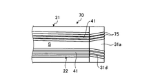
- FIG. 8 is a cross-sectional view schematically showing the optical fiber probe according to the third embodiment.
- parts that are different from the first and second embodiments will be described in order to avoid redundant descriptions, and parts that have the same configurations as those in the first and second embodiments will be described with the same reference numerals.
- the optical fiber probe 70 of the third embodiment includes an optical window 75 that is inserted into the through holes 31 d and 61 d of the probe main bodies 21 and 51 in the optical fiber probes 11 and 50 of the first and second embodiments. And more. In the following description, the description is applied to the first embodiment.
- the optical window 75 is formed in a columnar shape (rod shape) using, for example, sapphire glass or quartz glass, and is inserted into the through hole 31d and fixed to the through hole 31d by brazing or press-fitting.
- the optical window 75 is plated on the outer peripheral surface thereof to increase the light reflectance within the optical window 75. Then, the front end portion of the optical fiber 22 abuts on the rear end side of the optical window 75.
- Scattering processing is applied to the tip of the light transmission fiber 41 of the optical fiber 22, and the light emitted from the light transmission fiber 41 is scattered and enters the optical window 75.
- the through hole 31d through which the optical window 75 is inserted is formed in a predetermined shape so that the emitted light has a predetermined emission angle and a predetermined diffusion angle.
- the tip portion including the bottom plate portion 31 a of the probe main body 21 to which the optical window 75 is fixed is formed using, for example, Kovar in order to approach the thermal expansion coefficient of the optical window 75.
- the optical window 75 can partition the outside of the probe body 21 and the internal space S of the probe body 21. For this reason, since the optical fiber 22 is not exposed to the outside of the probe main body 21 and the optical fiber 22 can be stored in the internal space S, the exposure of the optical fiber 22 to the external environment can be suppressed. it can.
- the optical fiber 22 may have a configuration in which the large diameter portion 22b is omitted, or may be the small diameter portion 22a over the entire length.
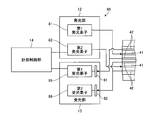
- FIG. 9 is a schematic configuration diagram schematically illustrating the optical fiber measurement device according to the fourth embodiment.
- parts that are different from those in the first to third embodiments will be described in order to avoid duplicate descriptions, and parts that have the same configuration as those in the first to third embodiments will be described with the same reference numerals.
- the optical fiber measuring device 80 of the fourth embodiment has different colors of light emitted from the two light transmitting fibers 41. That is, the light emitting unit 12 includes the first light emitting element 81 that emits light in the first color and the second light emitting element 82 that emits light in the second color. One light transmission fiber 41 is connected to the first light emitting element 81, and the other light transmission fiber 41 is connected to the second light emitting element 82.
- the light receiving unit 13 includes a first band pass filter 91 that transmits only light of the first color, a first light receiving element 95 that receives light transmitted through the first band pass filter 91, and only light of the second color. And a second light receiving element 96 that receives light transmitted through the second band pass filter 92.
- the first light receiving element 95 is connected to a group of a plurality of light receiving fibers 42 provided around one light transmitting fiber 41, and the second light receiving element 96 is disposed around the other light transmitting fiber 41. A plurality of light receiving fibers 42 of another group provided are connected.
- the optical fiber measuring device 80 emits light of the first color and the second color from the light emitting unit 12 toward the two light transmission fibers 41. Then, the first color light emitted from one of the light transmission fibers 41 is applied to the moving blade 6, and the reflected light reflected from the moving blade 6 enters the detected surface P 1 of the probe main body 21. The second color light emitted from the other light transmitting fiber 41 is applied to the moving blade 6, and the reflected light reflected from the moving blade 6 is incident on the detected surface P ⁇ b> 1 of the probe main body 21.
- the light receiving unit 13 receives the reflected light incident from the detection surface P1 of the probe main body 21 through the group of light receiving fibers 42 and the first reflected light having the first color only through the first bandpass filter 91.
- the light receiving element 95 receives light.
- the light receiving unit 13 receives only the reflected light that has entered the second color through the second band-pass filter 92 and receives the reflected light that has entered from the detected surface P1 of the probe body 21 through the other light receiving fiber 42. Is received by the second light receiving element 96.
- the fourth embodiment even if the first color light emitted from one light transmission fiber 41 is incident on the other group of light receiving fibers 42, Only the second color light can be transmitted by the two-band pass filter 92. Similarly, even when the second color light emitted from the other light transmitting fiber 41 is incident on the group of light receiving fibers 42, the first band pass filter 91 of the light receiving unit 13 causes the first color to pass through the first color. It is possible to transmit only the light. In this way, the light receiving unit 13 can select the light to be received. For this reason, since light mixture (that is, crosstalk) between the plurality of light transmitting fibers 41 and the plurality of light receiving fibers 42 can be suppressed, erroneous detection of light in the light receiving unit 13 can be suppressed.
- light mixture that is, crosstalk
Landscapes
- Engineering & Computer Science (AREA)
- Mechanical Engineering (AREA)
- General Engineering & Computer Science (AREA)
- Physics & Mathematics (AREA)
- General Physics & Mathematics (AREA)
- Chemical & Material Sciences (AREA)
- Combustion & Propulsion (AREA)
- Length Measuring Devices By Optical Means (AREA)
- Turbine Rotor Nozzle Sealing (AREA)
Priority Applications (3)
| Application Number | Priority Date | Filing Date | Title |
|---|---|---|---|
| US15/757,836 US10605108B2 (en) | 2015-09-10 | 2016-06-29 | Optical fiber probe, optical fiber measuring device, and clearance control system |
| CN201680051901.0A CN108027231B (zh) | 2015-09-10 | 2016-06-29 | 光纤探头、光纤测量装置以及间距控制系统 |
| KR1020187006595A KR102127110B1 (ko) | 2015-09-10 | 2016-06-29 | 광 파이버 프로브, 광 파이버 계측 장치 및 클리어런스 제어 시스템 |
Applications Claiming Priority (2)
| Application Number | Priority Date | Filing Date | Title |
|---|---|---|---|
| JP2015-178656 | 2015-09-10 | ||
| JP2015178656A JP6712845B2 (ja) | 2015-09-10 | 2015-09-10 | 光ファイバプローブ、光ファイバ計測装置及びクリアランス制御システム |
Publications (1)
| Publication Number | Publication Date |
|---|---|
| WO2017043157A1 true WO2017043157A1 (ja) | 2017-03-16 |
Family
ID=58240708
Family Applications (1)
| Application Number | Title | Priority Date | Filing Date |
|---|---|---|---|
| PCT/JP2016/069278 Ceased WO2017043157A1 (ja) | 2015-09-10 | 2016-06-29 | 光ファイバプローブ、光ファイバ計測装置及びクリアランス制御システム |
Country Status (5)
| Country | Link |
|---|---|
| US (1) | US10605108B2 (enExample) |
| JP (1) | JP6712845B2 (enExample) |
| KR (1) | KR102127110B1 (enExample) |
| CN (1) | CN108027231B (enExample) |
| WO (1) | WO2017043157A1 (enExample) |
Cited By (2)
| Publication number | Priority date | Publication date | Assignee | Title |
|---|---|---|---|---|
| WO2017164149A1 (ja) * | 2016-03-22 | 2017-09-28 | 三菱重工業株式会社 | 光学センサ、回転機械及びクリアランス計測方法 |
| EP3569826A1 (en) * | 2018-05-16 | 2019-11-20 | United Technologies Corporation | Determination of a clearance and a position of a target |
Families Citing this family (12)
| Publication number | Priority date | Publication date | Assignee | Title |
|---|---|---|---|---|
| EP3282235B1 (en) * | 2016-08-08 | 2019-04-17 | Ansaldo Energia Switzerland AG | Gas turbine power plant comprising a temperature detecting device |
| FR3082224B1 (fr) * | 2018-06-07 | 2020-05-22 | Openfield | Debitmetre a mini-turbine et outil de fond de puits comprenant un reseau de debitmetre a mini-turbine pour fonctionner dans un puits d'hydrocarbures. |
| US11060847B2 (en) | 2019-10-30 | 2021-07-13 | General Electric Company | System and method for optical measurements in a rotary machine |
| US11400527B2 (en) | 2019-10-30 | 2022-08-02 | General Electric Company | System and method for machining a slot in an inner surface of a casing for a gas turbine engine |
| US11635750B2 (en) | 2019-10-30 | 2023-04-25 | General Electric Company | System and method for removably inserting a sensor assembly into a compressor casing |
| US10921113B1 (en) * | 2019-10-30 | 2021-02-16 | General Electric Company | System and method for optical measurements in a rotary machine |
| US11409022B2 (en) | 2019-10-30 | 2022-08-09 | General Electric Company | System and method for optical measurements in a rotary machine |
| CN213813363U (zh) * | 2020-07-28 | 2021-07-27 | 苏州优谱德精密仪器科技有限公司 | 一种光学探头 |
| US11714195B2 (en) | 2020-10-05 | 2023-08-01 | Raytheon Technologies Corporation | Optical time of arrival airfoil measurement probe |
| US20230160834A1 (en) * | 2021-11-23 | 2023-05-25 | Raytheon Technologies Corporation | Optical turbine engine blade damage detector |
| US12339113B2 (en) * | 2022-06-30 | 2025-06-24 | Ge Infrastructure Technology Llc | Apparatus and method for transmitting radiation to a rotating component |
| DE102024104748A1 (de) * | 2024-02-20 | 2025-08-21 | MTU Aero Engines AG | Vermessung eines Radialspaltes einer Gasturbinenbaugruppe |
Citations (8)
| Publication number | Priority date | Publication date | Assignee | Title |
|---|---|---|---|---|
| JPH0650743A (ja) * | 1991-01-22 | 1994-02-25 | Tesa Sa | 直線値測定用電子光学センサー |
| JP2007271993A (ja) * | 2006-03-31 | 2007-10-18 | Japan Aviation Electronics Industry Ltd | 光ファイバ端部及び光ファイバ端部の固定構造 |
| JP2010175542A (ja) * | 2009-01-28 | 2010-08-12 | General Electric Co <Ge> | 2物体間の間隔を推定するシステムおよび方法 |
| WO2011018996A1 (ja) * | 2009-08-10 | 2011-02-17 | 日本電信電話株式会社 | 光コネクタ及びその組立方法 |
| JP2012125551A (ja) * | 2010-11-25 | 2012-07-05 | Fujifilm Corp | 内視鏡用照明光学系ユニット及びその製造方法並びに内視鏡光学部材用接着剤 |
| US20120182563A1 (en) * | 2011-01-14 | 2012-07-19 | Prime Photonics, LC. | Optical Blade Clearance Probe |
| JP2013250209A (ja) * | 2012-06-01 | 2013-12-12 | Olympus Corp | バンドル型ファイバセンサ |
| CN104501728A (zh) * | 2014-12-12 | 2015-04-08 | 天津大学 | 一种基于全光纤叶尖定时的叶尖间隙测量方法 |
Family Cites Families (12)
| Publication number | Priority date | Publication date | Assignee | Title |
|---|---|---|---|---|
| DE3433351C1 (de) * | 1984-09-11 | 1986-01-02 | MTU Motoren- und Turbinen-Union München GmbH, 8000 München | Kapazitives Messsystem zur Messung des Abstandes zwischen zwei relativ zueinander beweglichen Teilen |
| US5275929A (en) | 1992-04-16 | 1994-01-04 | Eastman Kodak Company | Photographic silver halide material comprising tabular grains of specified dimensions |
| DE19601225C1 (de) * | 1996-01-15 | 1997-06-19 | Siemens Ag | Vorrichtung zur Radialspaltüberwachung einer Turbine |
| JP2002156556A (ja) | 2000-11-21 | 2002-05-31 | Mihara Seiki:Kk | 光ファイバーケーブルのコネクター接続治具 |
| US7540704B2 (en) * | 2004-06-23 | 2009-06-02 | Kulite Semiconductor Products, Inc. | Method and system for determining gas turbine tip clearance |
| JP4476116B2 (ja) * | 2004-12-27 | 2010-06-09 | 三菱重工業株式会社 | ガスタービン |
| US8591188B2 (en) * | 2005-04-26 | 2013-11-26 | General Electric Company | Displacement sensor system and method of operation |
| US8042412B2 (en) | 2008-06-25 | 2011-10-25 | General Electric Company | Turbomachinery system fiberoptic multi-parameter sensing system and method |
| US20100079136A1 (en) * | 2008-09-29 | 2010-04-01 | Rosemount Aerospace Inc. | Blade tip clearance measurement sensor and method for gas turbine engines |
| JP2011107609A (ja) | 2009-11-20 | 2011-06-02 | Sumitomo Electric Ind Ltd | 光コネクタの検査方法および検査装置 |
| GB201021327D0 (en) * | 2010-12-16 | 2011-01-26 | Rolls Royce Plc | Clearance control arrangement |
| US20180058249A1 (en) * | 2016-08-31 | 2018-03-01 | General Electric Technology Gmbh | Valve Stroke And Spindle Way Counter Module For A Valve And Actuator Monitoring System |
-
2015
- 2015-09-10 JP JP2015178656A patent/JP6712845B2/ja active Active
-
2016
- 2016-06-29 KR KR1020187006595A patent/KR102127110B1/ko active Active
- 2016-06-29 CN CN201680051901.0A patent/CN108027231B/zh active Active
- 2016-06-29 WO PCT/JP2016/069278 patent/WO2017043157A1/ja not_active Ceased
- 2016-06-29 US US15/757,836 patent/US10605108B2/en active Active
Patent Citations (8)
| Publication number | Priority date | Publication date | Assignee | Title |
|---|---|---|---|---|
| JPH0650743A (ja) * | 1991-01-22 | 1994-02-25 | Tesa Sa | 直線値測定用電子光学センサー |
| JP2007271993A (ja) * | 2006-03-31 | 2007-10-18 | Japan Aviation Electronics Industry Ltd | 光ファイバ端部及び光ファイバ端部の固定構造 |
| JP2010175542A (ja) * | 2009-01-28 | 2010-08-12 | General Electric Co <Ge> | 2物体間の間隔を推定するシステムおよび方法 |
| WO2011018996A1 (ja) * | 2009-08-10 | 2011-02-17 | 日本電信電話株式会社 | 光コネクタ及びその組立方法 |
| JP2012125551A (ja) * | 2010-11-25 | 2012-07-05 | Fujifilm Corp | 内視鏡用照明光学系ユニット及びその製造方法並びに内視鏡光学部材用接着剤 |
| US20120182563A1 (en) * | 2011-01-14 | 2012-07-19 | Prime Photonics, LC. | Optical Blade Clearance Probe |
| JP2013250209A (ja) * | 2012-06-01 | 2013-12-12 | Olympus Corp | バンドル型ファイバセンサ |
| CN104501728A (zh) * | 2014-12-12 | 2015-04-08 | 天津大学 | 一种基于全光纤叶尖定时的叶尖间隙测量方法 |
Cited By (2)
| Publication number | Priority date | Publication date | Assignee | Title |
|---|---|---|---|---|
| WO2017164149A1 (ja) * | 2016-03-22 | 2017-09-28 | 三菱重工業株式会社 | 光学センサ、回転機械及びクリアランス計測方法 |
| EP3569826A1 (en) * | 2018-05-16 | 2019-11-20 | United Technologies Corporation | Determination of a clearance and a position of a target |
Also Published As
| Publication number | Publication date |
|---|---|
| KR20180039118A (ko) | 2018-04-17 |
| CN108027231B (zh) | 2020-04-14 |
| JP2017053762A (ja) | 2017-03-16 |
| JP6712845B2 (ja) | 2020-06-24 |
| KR102127110B1 (ko) | 2020-06-26 |
| CN108027231A (zh) | 2018-05-11 |
| US20180340441A1 (en) | 2018-11-29 |
| US10605108B2 (en) | 2020-03-31 |
Similar Documents
| Publication | Publication Date | Title |
|---|---|---|
| WO2017043157A1 (ja) | 光ファイバプローブ、光ファイバ計測装置及びクリアランス制御システム | |
| US11639872B1 (en) | Combustion monitoring system | |
| WO2010129073A1 (en) | Method and apparatus for spectroscopic measurements | |
| NO317221B1 (no) | Selvkalibrerende fiberoptiske trykk-, strekk- og temperatursensorer | |
| US20100321703A1 (en) | Optical sensor | |
| US8009939B2 (en) | Fiberoptic clearance detection system and method | |
| GB2493771A (en) | Optical sensor with thermal gradient between high-temperature sensor element and conventional lens and fibre | |
| CN110631616B (zh) | 一种超高温微型光纤efpi应变传感器 | |
| WO2017159770A1 (ja) | 光計測装置、光計測方法及び回転機械 | |
| TWI460405B (zh) | Light amount measuring device and light amount measuring method | |
| CN105067838B (zh) | 一种干涉型光纤加速度计探头及光纤加速度计系统 | |
| CN109959353A (zh) | 一种补偿式角度传感器 | |
| CN109632664B (zh) | 一种用于安装高温及振动条件下光学探头的装置 | |
| US12104933B2 (en) | Optical sensor and physical quantity measurement device | |
| US20210140337A1 (en) | Turbine and compressor blade deformation and axial shift monitoring by pattern deployment and tracking in blade pockets | |
| US11237134B2 (en) | Acoustic emission sensor having at least two mechanical coupling elements | |
| JP6629118B2 (ja) | 光学センサ及び回転機械 | |
| RU154470U1 (ru) | Термочувствительный спектральный преобразователь | |
| JP7513759B2 (ja) | 光学センサおよび物理量測定装置 | |
| US12044566B2 (en) | Measuring device comprising a connecting optical fibre and a measuring equipment for instrumentation of an aeronautical system, and an aeronautical system comprising such a measuring device | |
| Kishore et al. | Non-contact vibration sensor using bifurcated bundle glass fiber for real time monitoring | |
| CN115326232A (zh) | 温度传感器、无源多点温度测量装置和多点温度测量方法 | |
| GB2441782A (en) | Apparatus for measurement of temperature | |
| CN112525236A (zh) | 光纤传感器轴承组件、轴承状态监测系统及测量方法 | |
| FR3103893A1 (fr) | Système et procédé d’identification de paramètres d’un capteur fixé sur un carter |
Legal Events
| Date | Code | Title | Description |
|---|---|---|---|
| 121 | Ep: the epo has been informed by wipo that ep was designated in this application |
Ref document number: 16844023 Country of ref document: EP Kind code of ref document: A1 |
|
| WWE | Wipo information: entry into national phase |
Ref document number: 15757836 Country of ref document: US |
|
| ENP | Entry into the national phase |
Ref document number: 20187006595 Country of ref document: KR Kind code of ref document: A |
|
| NENP | Non-entry into the national phase |
Ref country code: DE |
|
| 122 | Ep: pct application non-entry in european phase |
Ref document number: 16844023 Country of ref document: EP Kind code of ref document: A1 |