WO2017038424A1 - 表示装置 - Google Patents
表示装置 Download PDFInfo
- Publication number
- WO2017038424A1 WO2017038424A1 PCT/JP2016/073686 JP2016073686W WO2017038424A1 WO 2017038424 A1 WO2017038424 A1 WO 2017038424A1 JP 2016073686 W JP2016073686 W JP 2016073686W WO 2017038424 A1 WO2017038424 A1 WO 2017038424A1
- Authority
- WO
- WIPO (PCT)
- Prior art keywords
- light
- display device
- image
- vehicle
- light guide
- Prior art date
Links
Images


Classifications
-
- H—ELECTRICITY
- H05—ELECTRIC TECHNIQUES NOT OTHERWISE PROVIDED FOR
- H05B—ELECTRIC HEATING; ELECTRIC LIGHT SOURCES NOT OTHERWISE PROVIDED FOR; CIRCUIT ARRANGEMENTS FOR ELECTRIC LIGHT SOURCES, IN GENERAL
- H05B33/00—Electroluminescent light sources
- H05B33/02—Details
-
- B—PERFORMING OPERATIONS; TRANSPORTING
- B60—VEHICLES IN GENERAL
- B60K—ARRANGEMENT OR MOUNTING OF PROPULSION UNITS OR OF TRANSMISSIONS IN VEHICLES; ARRANGEMENT OR MOUNTING OF PLURAL DIVERSE PRIME-MOVERS IN VEHICLES; AUXILIARY DRIVES FOR VEHICLES; INSTRUMENTATION OR DASHBOARDS FOR VEHICLES; ARRANGEMENTS IN CONNECTION WITH COOLING, AIR INTAKE, GAS EXHAUST OR FUEL SUPPLY OF PROPULSION UNITS IN VEHICLES
- B60K35/00—Instruments specially adapted for vehicles; Arrangement of instruments in or on vehicles
- B60K35/20—Output arrangements, i.e. from vehicle to user, associated with vehicle functions or specially adapted therefor
- B60K35/21—Output arrangements, i.e. from vehicle to user, associated with vehicle functions or specially adapted therefor using visual output, e.g. blinking lights or matrix displays
- B60K35/22—Display screens
-
- B—PERFORMING OPERATIONS; TRANSPORTING
- B60—VEHICLES IN GENERAL
- B60K—ARRANGEMENT OR MOUNTING OF PROPULSION UNITS OR OF TRANSMISSIONS IN VEHICLES; ARRANGEMENT OR MOUNTING OF PLURAL DIVERSE PRIME-MOVERS IN VEHICLES; AUXILIARY DRIVES FOR VEHICLES; INSTRUMENTATION OR DASHBOARDS FOR VEHICLES; ARRANGEMENTS IN CONNECTION WITH COOLING, AIR INTAKE, GAS EXHAUST OR FUEL SUPPLY OF PROPULSION UNITS IN VEHICLES
- B60K35/00—Instruments specially adapted for vehicles; Arrangement of instruments in or on vehicles
- B60K35/20—Output arrangements, i.e. from vehicle to user, associated with vehicle functions or specially adapted therefor
- B60K35/21—Output arrangements, i.e. from vehicle to user, associated with vehicle functions or specially adapted therefor using visual output, e.g. blinking lights or matrix displays
- B60K35/23—Head-up displays [HUD]
-
- B—PERFORMING OPERATIONS; TRANSPORTING
- B60—VEHICLES IN GENERAL
- B60K—ARRANGEMENT OR MOUNTING OF PROPULSION UNITS OR OF TRANSMISSIONS IN VEHICLES; ARRANGEMENT OR MOUNTING OF PLURAL DIVERSE PRIME-MOVERS IN VEHICLES; AUXILIARY DRIVES FOR VEHICLES; INSTRUMENTATION OR DASHBOARDS FOR VEHICLES; ARRANGEMENTS IN CONNECTION WITH COOLING, AIR INTAKE, GAS EXHAUST OR FUEL SUPPLY OF PROPULSION UNITS IN VEHICLES
- B60K35/00—Instruments specially adapted for vehicles; Arrangement of instruments in or on vehicles
- B60K35/20—Output arrangements, i.e. from vehicle to user, associated with vehicle functions or specially adapted therefor
- B60K35/28—Output arrangements, i.e. from vehicle to user, associated with vehicle functions or specially adapted therefor characterised by the type of the output information, e.g. video entertainment or vehicle dynamics information; characterised by the purpose of the output information, e.g. for attracting the attention of the driver
-
- B—PERFORMING OPERATIONS; TRANSPORTING
- B60—VEHICLES IN GENERAL
- B60K—ARRANGEMENT OR MOUNTING OF PROPULSION UNITS OR OF TRANSMISSIONS IN VEHICLES; ARRANGEMENT OR MOUNTING OF PLURAL DIVERSE PRIME-MOVERS IN VEHICLES; AUXILIARY DRIVES FOR VEHICLES; INSTRUMENTATION OR DASHBOARDS FOR VEHICLES; ARRANGEMENTS IN CONNECTION WITH COOLING, AIR INTAKE, GAS EXHAUST OR FUEL SUPPLY OF PROPULSION UNITS IN VEHICLES
- B60K35/00—Instruments specially adapted for vehicles; Arrangement of instruments in or on vehicles
- B60K35/60—Instruments characterised by their location or relative disposition in or on vehicles
-
- G—PHYSICS
- G02—OPTICS
- G02B—OPTICAL ELEMENTS, SYSTEMS OR APPARATUS
- G02B30/00—Optical systems or apparatus for producing three-dimensional [3D] effects, e.g. stereoscopic images
- G02B30/20—Optical systems or apparatus for producing three-dimensional [3D] effects, e.g. stereoscopic images by providing first and second parallax images to an observer's left and right eyes
- G02B30/26—Optical systems or apparatus for producing three-dimensional [3D] effects, e.g. stereoscopic images by providing first and second parallax images to an observer's left and right eyes of the autostereoscopic type
-
- G—PHYSICS
- G02—OPTICS
- G02B—OPTICAL ELEMENTS, SYSTEMS OR APPARATUS
- G02B6/00—Light guides; Structural details of arrangements comprising light guides and other optical elements, e.g. couplings
- G02B6/0001—Light guides; Structural details of arrangements comprising light guides and other optical elements, e.g. couplings specially adapted for lighting devices or systems
-
- G—PHYSICS
- G03—PHOTOGRAPHY; CINEMATOGRAPHY; ANALOGOUS TECHNIQUES USING WAVES OTHER THAN OPTICAL WAVES; ELECTROGRAPHY; HOLOGRAPHY
- G03B—APPARATUS OR ARRANGEMENTS FOR TAKING PHOTOGRAPHS OR FOR PROJECTING OR VIEWING THEM; APPARATUS OR ARRANGEMENTS EMPLOYING ANALOGOUS TECHNIQUES USING WAVES OTHER THAN OPTICAL WAVES; ACCESSORIES THEREFOR
- G03B21/00—Projectors or projection-type viewers; Accessories therefor
- G03B21/10—Projectors with built-in or built-on screen
-
- G—PHYSICS
- G03—PHOTOGRAPHY; CINEMATOGRAPHY; ANALOGOUS TECHNIQUES USING WAVES OTHER THAN OPTICAL WAVES; ELECTROGRAPHY; HOLOGRAPHY
- G03B—APPARATUS OR ARRANGEMENTS FOR TAKING PHOTOGRAPHS OR FOR PROJECTING OR VIEWING THEM; APPARATUS OR ARRANGEMENTS EMPLOYING ANALOGOUS TECHNIQUES USING WAVES OTHER THAN OPTICAL WAVES; ACCESSORIES THEREFOR
- G03B21/00—Projectors or projection-type viewers; Accessories therefor
- G03B21/14—Details
- G03B21/20—Lamp housings
- G03B21/2006—Lamp housings characterised by the light source
-
- G—PHYSICS
- G03—PHOTOGRAPHY; CINEMATOGRAPHY; ANALOGOUS TECHNIQUES USING WAVES OTHER THAN OPTICAL WAVES; ELECTROGRAPHY; HOLOGRAPHY
- G03B—APPARATUS OR ARRANGEMENTS FOR TAKING PHOTOGRAPHS OR FOR PROJECTING OR VIEWING THEM; APPARATUS OR ARRANGEMENTS EMPLOYING ANALOGOUS TECHNIQUES USING WAVES OTHER THAN OPTICAL WAVES; ACCESSORIES THEREFOR
- G03B21/00—Projectors or projection-type viewers; Accessories therefor
- G03B21/54—Accessories
- G03B21/56—Projection screens
- G03B21/60—Projection screens characterised by the nature of the surface
- G03B21/62—Translucent screens
-
- G—PHYSICS
- G03—PHOTOGRAPHY; CINEMATOGRAPHY; ANALOGOUS TECHNIQUES USING WAVES OTHER THAN OPTICAL WAVES; ELECTROGRAPHY; HOLOGRAPHY
- G03B—APPARATUS OR ARRANGEMENTS FOR TAKING PHOTOGRAPHS OR FOR PROJECTING OR VIEWING THEM; APPARATUS OR ARRANGEMENTS EMPLOYING ANALOGOUS TECHNIQUES USING WAVES OTHER THAN OPTICAL WAVES; ACCESSORIES THEREFOR
- G03B29/00—Combinations of cameras, projectors or photographic printing apparatus with non-photographic non-optical apparatus, e.g. clocks or weapons; Cameras having the shape of other objects
-
- B—PERFORMING OPERATIONS; TRANSPORTING
- B60—VEHICLES IN GENERAL
- B60K—ARRANGEMENT OR MOUNTING OF PROPULSION UNITS OR OF TRANSMISSIONS IN VEHICLES; ARRANGEMENT OR MOUNTING OF PLURAL DIVERSE PRIME-MOVERS IN VEHICLES; AUXILIARY DRIVES FOR VEHICLES; INSTRUMENTATION OR DASHBOARDS FOR VEHICLES; ARRANGEMENTS IN CONNECTION WITH COOLING, AIR INTAKE, GAS EXHAUST OR FUEL SUPPLY OF PROPULSION UNITS IN VEHICLES
- B60K2360/00—Indexing scheme associated with groups B60K35/00 or B60K37/00 relating to details of instruments or dashboards
- B60K2360/16—Type of output information
- B60K2360/178—Warnings
-
- B—PERFORMING OPERATIONS; TRANSPORTING
- B60—VEHICLES IN GENERAL
- B60K—ARRANGEMENT OR MOUNTING OF PROPULSION UNITS OR OF TRANSMISSIONS IN VEHICLES; ARRANGEMENT OR MOUNTING OF PLURAL DIVERSE PRIME-MOVERS IN VEHICLES; AUXILIARY DRIVES FOR VEHICLES; INSTRUMENTATION OR DASHBOARDS FOR VEHICLES; ARRANGEMENTS IN CONNECTION WITH COOLING, AIR INTAKE, GAS EXHAUST OR FUEL SUPPLY OF PROPULSION UNITS IN VEHICLES
- B60K2360/00—Indexing scheme associated with groups B60K35/00 or B60K37/00 relating to details of instruments or dashboards
- B60K2360/20—Optical features of instruments
- B60K2360/33—Illumination features
- B60K2360/334—Projection means
-
- G—PHYSICS
- G02—OPTICS
- G02B—OPTICAL ELEMENTS, SYSTEMS OR APPARATUS
- G02B30/00—Optical systems or apparatus for producing three-dimensional [3D] effects, e.g. stereoscopic images
- G02B30/20—Optical systems or apparatus for producing three-dimensional [3D] effects, e.g. stereoscopic images by providing first and second parallax images to an observer's left and right eyes
- G02B30/34—Stereoscopes providing a stereoscopic pair of separated images corresponding to parallactically displaced views of the same object, e.g. 3D slide viewers
- G02B30/36—Stereoscopes providing a stereoscopic pair of separated images corresponding to parallactically displaced views of the same object, e.g. 3D slide viewers using refractive optical elements, e.g. prisms, in the optical path between the images and the observer
-
- G—PHYSICS
- G02—OPTICS
- G02B—OPTICAL ELEMENTS, SYSTEMS OR APPARATUS
- G02B6/00—Light guides; Structural details of arrangements comprising light guides and other optical elements, e.g. couplings
- G02B6/0001—Light guides; Structural details of arrangements comprising light guides and other optical elements, e.g. couplings specially adapted for lighting devices or systems
- G02B6/0011—Light guides; Structural details of arrangements comprising light guides and other optical elements, e.g. couplings specially adapted for lighting devices or systems the light guides being planar or of plate-like form
- G02B6/0033—Means for improving the coupling-out of light from the light guide
- G02B6/0035—Means for improving the coupling-out of light from the light guide provided on the surface of the light guide or in the bulk of it
- G02B6/0036—2-D arrangement of prisms, protrusions, indentations or roughened surfaces
-
- G—PHYSICS
- G02—OPTICS
- G02B—OPTICAL ELEMENTS, SYSTEMS OR APPARATUS
- G02B6/00—Light guides; Structural details of arrangements comprising light guides and other optical elements, e.g. couplings
- G02B6/24—Coupling light guides
- G02B6/26—Optical coupling means
- G02B6/34—Optical coupling means utilising prism or grating
Definitions
- the present invention relates to a display device that displays an image as an interior member of a vehicle such as a vehicle.
- Patent Literature 1 includes a warning indicator in which all of a plurality of display items that can be individually displayed are arranged in a list, and a multi-display that can display details of the plurality of display items.
- a vehicle display device is disclosed that displays a corresponding display item of a corresponding warning indicator when displaying a warning display item.
- This invention is made
- an object is to provide a display device capable of improving visibility.
- a display device described in the present application is a display device that is mounted as an interior member of a vehicle and displays an image in the vehicle, and includes a light source that emits light, and light incident from the light source.
- a light guide member for guiding the light, and the light guide member changes an exit surface for emitting the incident light and an optical path of the incident light to the exit surface side to a convergence point or convergence line outside the member.
- a plurality of light converging portions that are emitted in a direction of convergence or a direction of divergence from a convergence point or a convergence line outside the member and imaged outside the member.
- the display device described in the present application is characterized in that the light converging unit forms an image along a virtual plane that is oblique or orthogonal to the emission surface.
- the light guide member can be disposed on an upper part of the dashboard with an emission surface facing upward, and the light converging unit forms an image on the disposed dashboard. It is characterized by.
- the display device described in the present application is characterized in that the light guide member can be disposed on the glass surface of the vehicle with the emission surface facing the vehicle interior.
- the display device is characterized in that the light guide member can be disposed in at least one of a glove box, a center console, an armrest, a door trim, a container trim, and a front seat that are interior members. To do.
- the display device described in the present application is characterized in that the light converging unit forms an image at a position visible from the driver's seat.
- the display device described in the present application is characterized in that the light converging unit forms an image at a position visible from a seat behind the driver seat.
- the light converging unit forms an image so as to display an image indicating at least one of a display regarding a vehicle state, a display regarding boarding, and a display regarding driving of the vehicle.
- the display device described in the present application is a display device that is mounted on a vehicle and displays an image therein, and includes a light source that emits light and a light guide member that guides light incident from the light source.
- the optical member changes the exit surface that emits the incident light and the optical path of the incident light to the exit surface side, and converges at a convergence point or convergence line outside the member, or outside the member.
- a plurality of light converging portions that are emitted in a direction of diverging from a convergence point or a convergence line and imaged outside the member.
- the display device described in the present application is capable of displaying an image formed in a vehicle such as a passenger car.
- the present invention is mounted as an interior member and includes a light source and a light guide member.
- the light guide member forms an image of light incident from the light source. Accordingly, display contents such as various warning lights can be displayed outside the apparatus, for example, in a space on the dashboard. Therefore, it is possible to display easily without being greatly restricted by the design of other interior parts, for example, the design of the instrument panel, and while reducing the design restrictions of other parts. Play.
- FIG. 1 shows schematically the display apparatus which concerns on this invention with the image formed on space. It is a conceptual diagram which shows typically the cross section of the display apparatus which concerns on this invention, and the outline of an optical path. It is a conceptual diagram which shows typically the cross section of the display apparatus which concerns on this invention, and the outline of an optical path. It is the schematic which shows the driver's seat vicinity in the vehicle carrying the display apparatus which concerns on the 1st Embodiment of this invention as an interior member. BRIEF DESCRIPTION OF THE DRAWINGS FIG.
- FIG. 1 is a conceptual diagram schematically showing a cross section in the vicinity of a driver's seat of a vehicle equipped with a display device according to a first embodiment of the present invention as an interior member and an outline of the driver.
- It is explanatory drawing which shows typically the relationship between the output surface of the display apparatus which concerns on the 1st Embodiment of this invention, and the image formed.
- It is the schematic which shows the driver's seat vicinity in the vehicle carrying the display apparatus which concerns on the 2nd Embodiment of this invention as an interior member.
- It is the schematic which shows the back seat vicinity in the vehicle which mounts the display apparatus which concerns on the 3rd Embodiment of this invention as an interior member.
- FIG. 1 is an explanatory view schematically showing a display device according to the present invention together with an image formed on a space.
- the figure used for description is shown schematically and schematically for the purpose of easy-to-understand explanation. Further, the drawings used for the description may not be drawn at an actual scale ratio including the aspect ratio of each member, the size ratio between members, and the like.
- the display device 1 includes a light source 10 that emits light, and a light guide plate (light guide member) 11 that guides light incident from the light source 10.
- the light source 10 is configured using a light emitting element such as an LED, and emits light to the light guide plate 11 by light emission.
- the light guide plate 11 is made of a transparent, high refractive index resin material such as polycarbonate resin (PC) or polymethyl methacrylate resin (PMMA), or an inorganic material such as glass. It is formed in a rectangular surface shape such as a plate shape. As illustrated in FIG. 1, the term “planar shape” as used herein means that the length (thickness) in the thickness direction (Z-axis direction) perpendicular to the direction is smaller than the two-dimensional surface direction (XY plane).
- the light guide plate 11 is formed in a rectangular parallelepiped shape, but in the thickness direction (Z-axis direction) as compared to the longitudinal direction (X-axis direction) and the short-side direction (Y-axis direction) that are two-dimensionally spreading planar. ) Has a small length.
- One of the surfaces on one end side of the light guide plate 11 in the longitudinal direction that is, the surface constituted by the rectangular short side and the side in the thickness direction is a light incident end surface 12 to which the light source 10 is attached.
- the light emitted from 10 enters.
- the light guide plate 11 guides light that has entered the light guide plate 11 from the light incident end face 12 in a planar shape.
- the planar light guide plate 11 includes an output surface 13 that emits light incident from the light source 10, and a back surface 14 opposite to the output surface 13.
- the X axis is the short side direction of the light guide plate 11, that is, the short side direction of the rectangle.
- the Y axis is the longitudinal direction of the light guide plate 11, that is, the long side direction of the rectangle, and the direction from the light incident end face 12 side to the opposite end face is the positive direction.
- the Z axis is the thickness direction of the light guide plate 11, and the direction from the back surface 14 to the exit surface 13 is a positive direction.
- the X axis, the Y axis, and the Z axis are used with reference to the surface including the main part of the emission surface 13 or a surface approximated to the surface. Shall.
- each light converging unit 15 is a part that changes the path of light incident from the light incident end face 12, that is, the optical path to the exit surface 13 side.
- an optical surface such as a reflection surface 150 (see 150x, 150y in FIG. 2, 150x1, 150x2, 150x3 in FIG. 3) for reflecting the light incident from the light incident end surface 12 is provided in the light guide plate 11.
- a reflection surface 150 see 150x, 150y in FIG. 2, 150x1, 150x2, 150x3 in FIG. 3
- the slope formed by the notch functions as the reflecting surface 150.
- the reflection surface 150 of the light converging part 15 is formed substantially continuously in the X-axis direction.
- the plurality of light converging portions 15a, 15a,... Are formed along the line 16a, and the plurality of light converging portions 15b, 15b,.
- the plurality of light converging portions 15c, 15d,..., 15g are formed along the lines 16c, 16d,.
- the line 16 (lines 16a, 16b,..., 16g) is a virtual straight line extending substantially parallel to the X axis on the back surface.
- the arbitrary light converging portions 15, 15,... Are formed substantially continuously along a straight line 16 substantially parallel to the X axis, and the light incident on the light guide plate 11 is aligned in the X axis direction. It is led to each light converging part 15, 15,.
- the light converging unit 15 has a configuration such as a reflecting surface 150 that changes the optical path, changes the path of light incident on the reflecting surface 150 of the light converging unit 15, and exits from the exit surface 13 to emit each light.
- the convergence is made substantially to the convergence point P corresponding to the convergence unit 15.
- light converging units 15a, 15b,..., 15g are illustrated as a part of the light converging unit 15, and the light converging units 15a, 15b,. .., 15g, a plurality of light beams whose optical paths are changed converge to convergence points Pa, Pb,.
- each light converging unit 15 forms an image 17 by converging the light beam at each convergence point P to form an image.
- the light rays from the respective positions of the plurality of light converging portions 15 on the arbitrary line 16 are emitted from the light exit surface 13 by being reflected by optical surfaces such as the respective reflective surfaces 150 and emitted from the light exit surface 13 to the convergence point P. Converge. Therefore, the wavefronts of the light from the plurality of light converging units 15 become the wavefronts of light emitted from the convergence point P.
- the plurality of light converging portions 15 a on the line 16 a correspond to the convergence point Pa on the image 17.
- the light beams respectively guided to the plurality of light converging portions 15a on the line 16a are changed in optical path by each light converging portion 15a, are emitted from the emission surface 13, and converge at the convergence point Pa.
- the light reflected by the plurality of light converging units 15 on the other lines 16 also converges at the convergence point P.
- a wavefront of light that emits light from the corresponding convergence point P can be provided by an arbitrary light converging unit 15.
- the convergence points P corresponding to the respective light converging portions 15 are different from each other, and an image 17 recognized in space is formed by a collection of a plurality of converging points P respectively corresponding to the light converging portions 15.
- the display device 1 projects the image 17 as a stereoscopic image on the space.
- the image 17 illustrated in FIG. 1 is a three-dimensional image drawn with lines, and the lines that draw the image 17 are formed by a collection of a plurality of convergence points P respectively corresponding to the light converging unit 15.
- the display device 1 forms an image 17 as a three-dimensional image by forming an image of light emitted from the emission surface 13.
- the image 17 is a stereoscopic image that is recognized in space by the viewer.
- the stereoscopic image described in the present application refers to an image 17 that is recognized outside the display device 1 so as to be at a position different from the exit surface 13.
- the stereoscopic image includes not only a three-dimensional image but also a two-dimensional image that is recognized at a position distant from the emission surface 13 of the display device 1, for example.
- the term “stereoscopic image” as used herein refers not only to the image 17 recognized as a three-dimensional shape, but also to the concept including the two-dimensional shape image 17 recognized at a different position from the exit surface 13 of the display device 1. It shows an image 17 that is visually recognized as if it protruded from the light guide plate 11 of the display device 1.
- the light guided by the light guide plate 11 has directivity in the direction connecting each position in the light guide plate 11 and the light source 10, and spreads perpendicular to the direction connecting each position in the light guide plate 11 and the light source 10. Does not have.
- the light guided by the light guide plate 11 has directivity in the Y-axis direction at the position where the light converging part 15 is provided. , Does not spread in the X-axis direction. Therefore, for example, on a plane that includes the convergence point P and is parallel to the XZ plane, the light from the light converging unit 15 substantially converges to one convergence point P.
- the light from the light converging unit 15 converges on a convergence line including the convergence point P in space along the Y axis.
- the light from the light converging unit 15 converges to the convergence point P by paying attention to the convergence of the light in the XZ plane as appropriate.
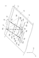
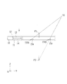
- FIGS. 2 and 3 are conceptual diagrams schematically showing a cross section and an outline of an optical path of the display device 1 according to the present invention.
- FIG. 2 shows a cross section parallel to the YZ plane
- FIG. 3 shows a cross section parallel to the XZ plane together with an image 17 visually recognized by an observer.
- 2 and 3 illustrate an example of forming an image 17 that imitates an arrow that spreads not only on the exit surface 13 side (Z-axis positive direction) of the light guide plate 11 but also on the back surface 14 side (Z-axis negative direction).
- the image 17 simulating an arrow is visually recognized such that the front part of the arrow protrudes from the emission surface 13 side and the rear part of the arrow protrudes from the back surface 14 side.
- the light source 10 is attached to the light incident end surface 12 of the light guide plate 11, and the light incident end surface 12 and the light exit surface 13 are substantially orthogonal to each other.
- the surface facing the emission surface 13 is a back surface 14, and the back surface 14 is also substantially orthogonal to the light incident end surface 12.
- the back surface 14 includes a flat surface that is substantially parallel to the emission surface 13 and an inclined surface that forms the reflecting surface 150 (150x, 150y) of the light converging portion 15 (15x, 15y).
- the flat surface of the back surface 14 has the function of spreading the light entering the light guide plate 11 from the light incident end surface 12 together with the light exit end surface 12 while totally reflecting the light, and spreading the light in the light guide plate 11 into a planar shape. is doing.
- the inclined reflecting surface 150 of the light converging unit 15 reflects the light that has entered the light guide plate 11 and changes the optical path toward the exit surface 13.
- the light emitted from the light source 10 and entering the light guide plate 11 from the light incident end surface 12 is guided in a state of being confined in the light guide plate 11 while repeating total reflection between the output surface 13 and the back surface 14. Propagates in a plane. Further, when the light propagating in the light guide plate 11 reaches any one of the reflection surfaces 150 forming the light converging portion 15, the light is reflected by the reflection surface 150 and the light is emitted from the emission surface 13 to the outside.
- the plurality of light converging portions 15x (light converging portions 15x1, 15x2, 15x3,...) Located on one line 16 include reflecting surfaces 150x1, 150x2, 150x3,. .
- wire 16 contains reflective surface 150y1, 150y2, 150y3, ..., respectively.
- the reflective surfaces 150x such as the reflective surfaces 150x1, 150x2, 150x3,... Reflect the light from the light source 10 in the direction along the straight line connecting the point on each reflective surface 150x and the convergence point P1.
- the light rays reflected by the reflecting surfaces 150x converge at the convergence point P1.
- the plurality of reflecting surfaces 150x included in each of the light converging portions 15x reflect the light incident from the light source 10 in a direction along a straight line connecting the point on each reflecting surface 150x and the convergence point P1.
- the display device 1 can provide light that travels from the convergence point P1 to any position within the range from the position V2 through the position V1 to the position V3.
- Such a convergence point P1 forms an image 17 that is recognized as if it has protruded to the exit surface 13 side.
- the reflecting surfaces 150y such as the reflecting surfaces 150y1, 150y2, 150y3,... Reflect the light incident from the light source 10 in the direction along the straight line connecting the point on the reflecting surface 150y and the convergence point P2.
- the extended lines of the respective light beams converge at the convergence point P2.
- the plurality of reflecting surfaces 150y included in each of the light converging portions 15y reflect light incident from the light source 10 in a direction along a straight line connecting the point on each reflecting surface 150 and the convergence point P2. .
- the display device 1 can provide light traveling from the convergence point P2 to any position within the range from the position V2 through the position V1 to the position V3.
- Such a convergence point P ⁇ b> 2 forms an image 17 that is recognized as if it has protruded to the opposite side (back surface 14 side) of the exit surface 13.
- the light guide plate 11 has a plurality of light converging portions 15 having convergence points P that are different from each other, and a three-dimensional image is obtained by a collection of a plurality of convergence points P including the convergence points P1 and P2.
- an image 17 can be formed. That is, the light guide plate 11 changes the path of the incident light to the exit surface 13 side, and exits in a direction that converges at the external convergence point P1 or the convergence line, or a direction that diverges from the external convergence point P2 or the convergence line.
- a plurality of light converging units 15 for image formation outside are provided.
- the display device 1 can form an image 17 outside the light guide plate 11 as a three-dimensional image that can be visually recognized by an observer by a plurality of convergence points P or a collection of convergence lines.
- the light guide plate 11 into which the light emitted from the light source 10 enters guides light in a plane parallel to the emission surface 13.
- a plurality of light converging portions 15 having a length in a direction (X axis direction) perpendicular to the light guide direction (Y axis direction) of the light guide plate 11 is formed in a plane parallel to the emission surface 13.
- the normal direction projected onto a plane parallel to the exit surface 13 changes continuously or intermittently along the length direction (X-axis direction) of each light converging unit 15.
- the light guided by the light guide plate 11 is substantially converged to one convergence point P or convergence line in the space by being reflected by the optical surface, or substantially from one convergence point P or convergence line in the space. Is emitted from the emission surface 13 as emitted light in the direction of divergence.
- the convergence point P or the convergence line is different between each of the plurality of light converging units 15 having different positions on the Y axis, and an image 17 is formed in the space by the collection of the plurality of convergence points P or the convergence lines.
- a three-dimensional image that is visually recognized so as to jump out on both the exit surface 13 side and the back surface 14 side will be explained.
- a stereoscopic image that is visually recognized so as to protrude only from the surface on one side may be formed.
- the reflection surface 150 is formed as the light converging unit 15, but various light converging units 15 can be used as long as the path of the light incident on the light guide plate 11 can be changed.
- the light converging portion 15 may be formed of a cylindrical type Fresnel lens, and the path of the incident light may be changed by the refraction action of the refracting surface (prism surface) of the Fresnel lens.
- the Fresnel lens may be configured by a plurality of portions each having a gap. It is also possible to form the light converging portion 15 with a diffraction grating and change the path of the incident light by the diffraction action. Furthermore, the path of the incident light can be changed by the reflection or refraction action of the prism.
- the distances between all the convergence points P and the exit surface 13 are not constant, for example, when forming an image 17 that spreads in three dimensions, or a two-dimensional image included in a plane oblique to the exit surface 13. 17 is formed such that the density of the converged light increases as the distance from the emission surface 13 increases. Thereby, the blur generated in the formed image 17 becomes substantially constant, and it is possible to form the image 17 that does not cause a viewer to feel uncomfortable.
- the light emitted from the light source 10 has entered the light guide plate 11 from the light incident end surface 12 which is the surface on the one end side in the longitudinal direction of the light guide plate 11, it is not limited to this.
- the back surface 14 is a light incident surface and light is incident from the back surface 14.
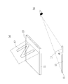
- FIG. 4 is a schematic diagram showing the vicinity of the driver's seat in the vehicle 2 in which the display device 1 according to the first embodiment of the present invention is mounted as an interior member.
- the vehicle 2 shown in FIG. 4 is a passenger car, and the display device 1 according to the present invention is mounted on the vehicle 2, and images 17 formed by the display device 1 are dashboards in front of the driver seat and in front of the passenger seat. 20 is projected.
- the projected image 17 is a display of contents such as a display relating to the state of the vehicle 2, a display relating to boarding, a display relating to driving of the vehicle 2, and the like, and particularly a display as a still image with a fixed display mode.
- a brake warning light relating to the state of the vehicle 2 a warning light indicating that the passenger seat and the driver's seat relating to boarding are worn, and a shift gear position relating to the driving of the vehicle 2 (“ N ”) is displayed as an indicator lamp.
- Such an image 17 includes not only the image illustrated in FIG.
- FIG. 4 but also a water temperature indicator lamp, a headlamp upward indicator lamp, a fog lamp indicator lamp, a 4WD indicator, an engine warning lamp, a hydraulic warning lamp, a charging warning lamp, a remaining fuel amount,
- An image indicating the contents of a warning light, an ABS warning light, an SRS warning light, a direction indicator light, and the like is displayed.
- the shift gear not only “N” illustrated in FIG. 4 but also positions such as “P”, “R”, “D”, “2”, “L”, and further an image indicating overdrive off. Is displayed.
- the displayed image 17 is surrounded by a rectangular frame indicated by a thin line, but in reality, the rectangular frame is included in a space including the rectangle indicated by the rectangular frame. Is displayed so that the image 17 shown in FIG.
- FIG. 5 is a conceptual diagram schematically showing a cross section in the vicinity of the driver's seat of the vehicle 2 on which the display device 1 according to the first embodiment of the present invention is mounted as an interior member, and an outline of the driver.
- FIG. 5 schematically shows a cross section parallel to the YZ plane.
- the display device 1 is disposed on the dashboard 20 of the vehicle 2 so that the light exit surface 13 of the light guide plate 11 faces upward.
- the light guide plate 11 of the display device 1 is formed of a flexible material, and the end portion on the light source 10 side having the light incident end face 12 and the end portion on the opposite side are bent, so that the dashboard 20 It is buried in.
- the central portion where the light converging portion 15 to be the emission surface 13 is formed has a planar shape and is arranged with the emission surface 13 facing upward.
- the light source 10 attached to the light incident end face 12 is embedded in the dashboard 20, is connected to a control device in the vehicle 2 (not shown), and appropriately emits light based on control from the control device.
- FIG. 6 is an explanatory diagram schematically showing the relationship between the exit surface 13 of the display device 1 and the formed image 7 according to the first embodiment of the present invention.
- FIG. 6A is a schematic perspective view schematically showing the relationship between the exit surface 13 of the light guide plate 11 provided in the display device 1 and the formed image 17, and
- FIG. 6B is a schematic side view. is there.
- the formed image 17 is formed on a plane that is substantially orthogonal to the line-of-sight direction from the driver who is the viewer, and the driver can easily visually recognize the formed image 17.
- the image 17 is formed so that the angle ⁇ is a right angle, that is, the emission surface and the virtual surface are orthogonal.
- the warning light for the passenger not wearing the seatbelt in the passenger seat is approximately the direction of the line of sight from the passenger on the passenger seat serving as the viewer. You may make it image-form on an orthogonal plane.
- the location of the display device 1, particularly the light guide plate 11, is not limited to the dashboard 20 described above.
- the display device 1 configured as described above does not need to place a warning light in the instrument panel, it is possible to improve the degree of freedom related to the design of the instrument panel, and the visibility of the warning light to be displayed is improved. It is also possible to form an image 17 of an appropriate size for improvement. Also, images that do not need to be displayed at the same time, for example, images indicating the position of the shift gear, can be displayed by switching the images related to each gear at the same position by laminating the respective light guide plates 11. The required space can be made compact.
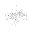
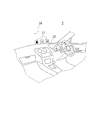
- FIG. 7 is a schematic diagram showing the vicinity of the driver's seat in the vehicle 2 in which the display device 1 according to the second embodiment of the present invention is mounted as an interior member.
- the image 17 formed by the display device 1 is projected on the dashboard 20 near the lower portion of the windshield 24 in front of the driver's seat. Since the image 17 to be formed is the same as that of the first embodiment described with reference to FIG. 4, the first embodiment will be referred to and detailed description thereof will be omitted.
- the displayed image 17 is surrounded by a rectangular frame indicated by a thin line, but actually, the rectangular frame is placed in a space including the rectangle indicated by the rectangular frame.
- the image 17 shown inside is displayed.
- FIG. 8 is a conceptual diagram schematically showing a cross section of the vicinity of the driver's seat of the vehicle 2 on which the display device 1 according to the second embodiment of the present invention is mounted as an interior member, and an outline of the driver.
- FIG. 8 schematically shows a cross section parallel to the YZ plane.
- the display device 1 is disposed below the windshield 24 of the vehicle 2 so that the light exit surface 13 of the light guide plate 11 faces downward.
- the light guide plate 11 of the display device 1 is formed of a flexible material, and an end portion on the light source 10 side having the light incident end face 12 is bent and embedded in the dashboard 20.
- part in which the light converging part 15 used as the output surface 13 was formed has planar shape, and is arrange
- the light source 10 attached to the light incident end face 12 is embedded in the dashboard 20, is connected to a control device in the vehicle 2 (not shown), and appropriately emits light based on control from the control device.
- the light converging part 15 formed in the light guide plate 11 is configured to form an image 17 only on the vehicle interior side, and indicates the position of the shift gear along a virtual plane that is oblique or orthogonal to the emission surface 13.
- An image is formed in the vicinity of the lower portion of the disposed windshield 24 (above the dashboard 20) so that various planar images such as images are formed.
- the formed image 17 is formed on a plane that is substantially orthogonal to the line-of-sight direction from the driver who is the viewer, and the driver can easily visually recognize the formed image 17.
- a warning light for a person not wearing the seat belt in the passenger seat is approximately the direction of the line of sight from the passenger on the passenger seat serving as the viewer. You may make it image-form on an orthogonal plane.
- the image 17 may not be entirely formed inside the vehicle, but may be partially or entirely formed outside the vehicle as long as there is no problem in visibility.
- the display device 1 configured as described above has excellent effects such as being able to provide necessary information to the driver while increasing the degree of freedom in designing the interior of the vehicle 2.
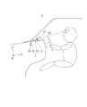
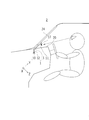
- FIG. 9 is a schematic view showing the vicinity of the rear seat in the vehicle 2 in which the display device 1 according to the third embodiment of the present invention is mounted as an interior member.
- the image 17 formed by the display device 1 is projected behind the headrest 25 of the front seat.
- the formed image 17 is, for example, an image 17 such as a warning light for a person not wearing a seat belt on the rear seat.
- the display device 1 can be disposed in various places such as a container trim (not shown) located behind the rear seat and a door trim (not shown) serving as an interior portion of the rear door.
- a container trim not shown
- a door trim not shown
- the image 17 is formed on the rear part of the vehicle 2, it is needless to say that the image formed by the passenger in the rear seat can be seen, for example, when the driver boarding the driver's seat confirms the rear. It is also possible to configure so that the formed image 17 can be visually recognized.
- various images such as a display regarding the state of the vehicle 2 are displayed by displaying an image 17 such as various warning lights from the display device 1 disposed in the container trim. It is possible to make the driver recognize various information.
- a form in which a two-dimensional planar image is formed is shown.
- the present invention is not limited to this, and can be developed in various forms such as a three-dimensional image. is there.
- positioned on the glass surface of the windshield 24 was shown, this invention is not limited to this, Glasses other than the windshield 24, for example, other glass surfaces, such as a rear glass and a side glass, are shown. It is possible to arrange.
- the form of mounting on a passenger car has been shown.
- Display apparatus 10
- Light source 11
- Light guide plate 12
- Light entrance end face 13
- Light exit face 15a, 15b, ..., 15x1, ..., 15y3
- Image P Pa, Pb,..., P1, P2
- Convergence point 2
- Vehicle 20
- Dashboard 21
- Center console 23
- Door trim 24
- Windshield 25
- Headrest 26 Front seat
Landscapes
- Engineering & Computer Science (AREA)
- Physics & Mathematics (AREA)
- General Physics & Mathematics (AREA)
- Chemical & Material Sciences (AREA)
- Combustion & Propulsion (AREA)
- Transportation (AREA)
- Mechanical Engineering (AREA)
- Optics & Photonics (AREA)
- Instrument Panels (AREA)
- Illuminated Signs And Luminous Advertising (AREA)
Priority Applications (3)
| Application Number | Priority Date | Filing Date | Title |
|---|---|---|---|
| CN201680041488.XA CN107850789B (zh) | 2015-09-01 | 2016-08-11 | 显示装置 |
| DE112016003971.9T DE112016003971B4 (de) | 2015-09-01 | 2016-08-11 | Displayvorrichtung |
| US15/876,056 US10841987B2 (en) | 2015-09-01 | 2018-01-19 | Display device |
Applications Claiming Priority (2)
| Application Number | Priority Date | Filing Date | Title |
|---|---|---|---|
| JP2015172243A JP6551068B2 (ja) | 2015-09-01 | 2015-09-01 | 表示装置 |
| JP2015-172243 | 2015-09-01 |
Related Child Applications (1)
| Application Number | Title | Priority Date | Filing Date |
|---|---|---|---|
| US15/876,056 Continuation US10841987B2 (en) | 2015-09-01 | 2018-01-19 | Display device |
Publications (1)
| Publication Number | Publication Date |
|---|---|
| WO2017038424A1 true WO2017038424A1 (ja) | 2017-03-09 |
Family
ID=58188861
Family Applications (1)
| Application Number | Title | Priority Date | Filing Date |
|---|---|---|---|
| PCT/JP2016/073686 WO2017038424A1 (ja) | 2015-09-01 | 2016-08-11 | 表示装置 |
Country Status (6)
Cited By (2)
| Publication number | Priority date | Publication date | Assignee | Title |
|---|---|---|---|---|
| JP2020009267A (ja) * | 2018-07-10 | 2020-01-16 | オムロン株式会社 | 入力装置 |
| CN113375119A (zh) * | 2017-06-22 | 2021-09-10 | 欧姆龙株式会社 | 车辆用发光装置 |
Families Citing this family (7)
| Publication number | Priority date | Publication date | Assignee | Title |
|---|---|---|---|---|
| JP6743419B2 (ja) * | 2015-11-10 | 2020-08-19 | オムロン株式会社 | 表示システム及びゲート装置 |
| JP6866738B2 (ja) | 2017-04-12 | 2021-04-28 | オムロン株式会社 | 画像表示ユニット |
| JP6885215B2 (ja) * | 2017-06-21 | 2021-06-09 | 日本精機株式会社 | 表示装置 |
| JP7063167B2 (ja) * | 2018-07-26 | 2022-05-09 | トヨタ自動車株式会社 | 表示制御装置、車両用表示装置、表示制御方法及びプログラム |
| WO2020081413A1 (en) * | 2018-10-16 | 2020-04-23 | Walbro Llc. | System for improved starting of a powered device including one or more threshold conditions |
| JP7239042B2 (ja) * | 2019-03-07 | 2023-03-14 | オムロン株式会社 | 発光装置、および車両用灯具 |
| JP7515384B2 (ja) | 2020-11-30 | 2024-07-12 | 本田技研工業株式会社 | 表示方法、及びシステム |
Citations (5)
| Publication number | Priority date | Publication date | Assignee | Title |
|---|---|---|---|---|
| JPH09152360A (ja) * | 1995-11-30 | 1997-06-10 | Toyoda Gosei Co Ltd | 車両用メータ |
| JP2000510603A (ja) * | 1996-02-28 | 2000-08-15 | ミン リ | 光波を処理するための光学構造 |
| JP2008275922A (ja) * | 2007-04-27 | 2008-11-13 | Fujikura Ltd | 表示装置 |
| JP2009540440A (ja) * | 2006-06-06 | 2009-11-19 | スリーエム イノベイティブ プロパティズ カンパニー | 仮想イメージを有するキーパッド |
| US20140268327A1 (en) * | 2013-03-15 | 2014-09-18 | Opsec Security Group, Inc. | Optically variable device exhibiting non-diffractive three-dimensional optical effect |
Family Cites Families (19)
| Publication number | Priority date | Publication date | Assignee | Title |
|---|---|---|---|---|
| DE4211728A1 (de) * | 1992-04-08 | 1993-10-14 | Zeiss Carl Fa | Holographische Anzeigevorrichtung |
| GB2301894B (en) | 1995-06-07 | 1998-03-11 | Toyoda Gosei Kk | Light-driven display device |
| US5668907A (en) * | 1996-01-11 | 1997-09-16 | Associated Universities, Inc. | Thin optical display panel |
| EP0818701B1 (en) * | 1996-07-09 | 2002-10-02 | Harness System Technologies Research, Ltd. | Display device |
| US20080024463A1 (en) * | 2001-02-22 | 2008-01-31 | Timothy Pryor | Reconfigurable tactile control display applications |
| CN100562686C (zh) * | 2004-02-20 | 2009-11-25 | 欧姆龙株式会社 | 面光源装置 |
| JP4254719B2 (ja) * | 2005-02-01 | 2009-04-15 | 株式会社デンソー | 車両用表示装置 |
| JP2006243641A (ja) * | 2005-03-07 | 2006-09-14 | Matsushita Electric Ind Co Ltd | 映像表示制御装置及び映像表示装置 |
| JP2007127871A (ja) * | 2005-11-04 | 2007-05-24 | Alps Electric Co Ltd | 立体表示装置 |
| US7830368B2 (en) | 2006-06-06 | 2010-11-09 | 3M Innovative Properties Company | Keypad with virtual image |
| DE102008015997B4 (de) * | 2007-03-29 | 2015-09-10 | Denso Corporation | Head-up Display |
| JPWO2009122716A1 (ja) * | 2008-04-03 | 2011-07-28 | パナソニック株式会社 | 情報表示装置 |
| MX2012012033A (es) | 2010-04-16 | 2013-05-20 | Flex Lighting Ii Llc | Dispositivo de iluminacion que comprende una guia de luz a base de pelicula. |
| CN101876753B (zh) * | 2010-06-03 | 2012-06-27 | 香港应用科技研究院有限公司 | 平视显示器的混合照明系统 |
| JP2012126251A (ja) * | 2010-12-15 | 2012-07-05 | Toyota Motor Corp | 車両用光源装置 |
| JP5941292B2 (ja) | 2012-02-10 | 2016-06-29 | 矢崎総業株式会社 | 車両用表示装置 |
| WO2014144403A2 (en) * | 2013-03-15 | 2014-09-18 | Seattle Photonics Associates | Optical system for head-up and near-to-eye displays |
| US20150091874A1 (en) * | 2013-09-30 | 2015-04-02 | Continental Automotive Systems, Inc. | Button selection trace light indicator |
| US9678351B2 (en) * | 2014-02-03 | 2017-06-13 | Lg Innotek Co., Ltd. | Stereoscopic display device and dashboard using the same |
-
2015
- 2015-09-01 JP JP2015172243A patent/JP6551068B2/ja active Active
-
2016
- 2016-08-11 CN CN201680041488.XA patent/CN107850789B/zh active Active
- 2016-08-11 DE DE112016003971.9T patent/DE112016003971B4/de active Active
- 2016-08-11 WO PCT/JP2016/073686 patent/WO2017038424A1/ja active Application Filing
- 2016-08-29 TW TW105127603A patent/TW201712300A/zh unknown
-
2018
- 2018-01-19 US US15/876,056 patent/US10841987B2/en active Active
Patent Citations (5)
| Publication number | Priority date | Publication date | Assignee | Title |
|---|---|---|---|---|
| JPH09152360A (ja) * | 1995-11-30 | 1997-06-10 | Toyoda Gosei Co Ltd | 車両用メータ |
| JP2000510603A (ja) * | 1996-02-28 | 2000-08-15 | ミン リ | 光波を処理するための光学構造 |
| JP2009540440A (ja) * | 2006-06-06 | 2009-11-19 | スリーエム イノベイティブ プロパティズ カンパニー | 仮想イメージを有するキーパッド |
| JP2008275922A (ja) * | 2007-04-27 | 2008-11-13 | Fujikura Ltd | 表示装置 |
| US20140268327A1 (en) * | 2013-03-15 | 2014-09-18 | Opsec Security Group, Inc. | Optically variable device exhibiting non-diffractive three-dimensional optical effect |
Cited By (5)
| Publication number | Priority date | Publication date | Assignee | Title |
|---|---|---|---|---|
| CN113375119A (zh) * | 2017-06-22 | 2021-09-10 | 欧姆龙株式会社 | 车辆用发光装置 |
| CN113375119B (zh) * | 2017-06-22 | 2024-02-06 | 欧姆龙株式会社 | 车辆用发光装置 |
| DE102018207618B4 (de) * | 2017-06-22 | 2025-04-30 | Omron Corporation | Lichtemittierende Vorrichtung für Fahrzeuge |
| JP2020009267A (ja) * | 2018-07-10 | 2020-01-16 | オムロン株式会社 | 入力装置 |
| JP7172207B2 (ja) | 2018-07-10 | 2022-11-16 | オムロン株式会社 | 入力装置 |
Also Published As
| Publication number | Publication date |
|---|---|
| US10841987B2 (en) | 2020-11-17 |
| CN107850789B (zh) | 2020-05-19 |
| JP6551068B2 (ja) | 2019-07-31 |
| US20180146519A1 (en) | 2018-05-24 |
| CN107850789A (zh) | 2018-03-27 |
| TW201712300A (zh) | 2017-04-01 |
| DE112016003971B4 (de) | 2023-07-20 |
| DE112016003971T5 (de) | 2018-06-07 |
| JP2017049420A (ja) | 2017-03-09 |
Similar Documents
| Publication | Publication Date | Title |
|---|---|---|
| JP6551068B2 (ja) | 表示装置 | |
| JP6493101B2 (ja) | 表示装置 | |
| JP6610099B2 (ja) | ミラーユニット及び表示装置 | |
| CN113375119B (zh) | 车辆用发光装置 | |
| US10981581B2 (en) | Display device | |
| CN110583015B (zh) | 图像显示单元 | |
| US20160004077A1 (en) | Virtual image generation device and head-up display | |
| WO2017038427A1 (ja) | 車両用表示装置 | |
| US10345586B2 (en) | Head-up display device | |
| US9417448B2 (en) | Display unit | |
| US11131851B2 (en) | Virtual image display device | |
| JP6515796B2 (ja) | ヘッドアップディスプレイ装置 | |
| JP2019009100A (ja) | 車両用発光装置 | |
| JP2011180177A (ja) | ヘッドアップディスプレイ装置 | |
| WO2021106665A1 (ja) | ヘッドアップディスプレイシステムおよび移動体 | |
| US20190082167A1 (en) | Alert display system | |
| JP5993117B2 (ja) | 車両用表示装置 | |
| JP2020194147A (ja) | 投影装置及びヘッドアップディスプレイ | |
| JP2018180262A (ja) | 車両用画像表示ユニット | |
| JP2017207632A (ja) | 投影型表示装置及びヘッドアップディスプレイ | |
| JP2013257584A (ja) | ヘッドアップディスプレイ装置 |
Legal Events
| Date | Code | Title | Description |
|---|---|---|---|
| 121 | Ep: the epo has been informed by wipo that ep was designated in this application |
Ref document number: 16841456 Country of ref document: EP Kind code of ref document: A1 |
|
| WWE | Wipo information: entry into national phase |
Ref document number: 112016003971 Country of ref document: DE |
|
| 122 | Ep: pct application non-entry in european phase |
Ref document number: 16841456 Country of ref document: EP Kind code of ref document: A1 |