WO2017038280A1 - ステアリング装置 - Google Patents
ステアリング装置 Download PDFInfo
- Publication number
- WO2017038280A1 WO2017038280A1 PCT/JP2016/071132 JP2016071132W WO2017038280A1 WO 2017038280 A1 WO2017038280 A1 WO 2017038280A1 JP 2016071132 W JP2016071132 W JP 2016071132W WO 2017038280 A1 WO2017038280 A1 WO 2017038280A1
- Authority
- WO
- WIPO (PCT)
- Prior art keywords
- shaft
- steering
- lock
- axial direction
- tightening
- Prior art date
- Legal status (The legal status is an assumption and is not a legal conclusion. Google has not performed a legal analysis and makes no representation as to the accuracy of the status listed.)
- Ceased
Links
Images




Classifications
-
- B—PERFORMING OPERATIONS; TRANSPORTING
- B62—LAND VEHICLES FOR TRAVELLING OTHERWISE THAN ON RAILS
- B62D—MOTOR VEHICLES; TRAILERS
- B62D1/00—Steering controls, i.e. means for initiating a change of direction of the vehicle
- B62D1/02—Steering controls, i.e. means for initiating a change of direction of the vehicle vehicle-mounted
- B62D1/16—Steering columns
- B62D1/18—Steering columns yieldable or adjustable, e.g. tiltable
- B62D1/184—Mechanisms for locking columns at selected positions
-
- B—PERFORMING OPERATIONS; TRANSPORTING
- B62—LAND VEHICLES FOR TRAVELLING OTHERWISE THAN ON RAILS
- B62D—MOTOR VEHICLES; TRAILERS
- B62D1/00—Steering controls, i.e. means for initiating a change of direction of the vehicle
- B62D1/02—Steering controls, i.e. means for initiating a change of direction of the vehicle vehicle-mounted
- B62D1/16—Steering columns
- B62D1/18—Steering columns yieldable or adjustable, e.g. tiltable
- B62D1/185—Steering columns yieldable or adjustable, e.g. tiltable adjustable by axial displacement, e.g. telescopically
Definitions
- the present invention relates to a steering device.
- Patent Document 1 In a steering apparatus that does not have a telescopic adjustment function, a structure in which a steering shaft is supported by a single tube jacket has been proposed (for example, Patent Document 1).
- an object of the present invention is to simplify the structure of a steering device capable of telescopic adjustment.
- the invention of claim 1 includes a steering shaft (3) including a first shaft (40; 40P; 40Q; 40R) and a second shaft (50; 50Q; 50R) which are fitted to each other so as to be expandable and contractable in the axial direction (X). 3P; 3Q; 3R), a single-tube jacket (16) that rotatably supports the first shaft and the second shaft and is supported by the vehicle body, and the first shaft and the second shaft that are connected to the shaft.
- a steering device (1; 1P; 1Q; 1R) including a lock mechanism (60) for fastening and releasing in a direction.
- one of the first shaft and the second shaft includes a hollow shaft that fits on the other outer periphery of the first shaft and the second shaft, and the hollow shaft is an ignition key.
- a key lock hole (44; 54) into which the lock key is fitted by operation may be formed.
- the lock mechanism is coupled to the steering shaft so as to be integrally rotatable so as to fasten and release the first shaft and the second shaft in the axial direction;
- the operation part (80) supported by the jacket may be included.
- the operation unit is displaceable to an operation position where the lock unit can be operated in a steering neutral state and a retreat position where the operation unit is retracted from the operation position so as to avoid interference with a rotation locus of the lock unit during steering. Also good.
- the lock portion is inserted into the pair of tightening portions (71, 72) facing the circumferential direction (Z) of the hollow shaft across the axial slit, and rotated by being inserted into the pair of tightening portions.
- a tightening shaft (73) that tightens the pair of tightening portions to reduce the diameter of the hollow shaft, and the operation portion is on the same axis (C2) as the tightening shaft in the steering neutral state.
- an operation shaft (81) supported by the jacket so as to be rotatable around the same axis and movable in the same axis direction, and fixed to the operation shaft and extending the operation shaft around the same axis.
- a lever (82) To rotate A lever (82), and the operation shaft and the tightening shaft are engaged with each other so as to be integrally rotatable when the operation portion is displaced to the operation position in the steering neutral state (74). , 83).
- the steering device may include an urging member (90) for urging the operation portion to the retracted position.
- the telescopic adjustment can be performed by extending and retracting the steering shaft in a state where the fastening of the first shaft and the second shaft is released by the lock mechanism.
- the structure can be simplified by using a single tube jacket.
- the structure can be simplified by forming the key lock hole in the hollow shaft constituting a part of the steering shaft.
- the lock portion can be operated by displacing the operation portion to the operation position.
- the operation unit can be retracted to the retracted position so that the operation unit does not interfere with the rotation locus of the lock unit during steering, and the rotation of the steering shaft can be permitted.
- the operating lever when the operating lever is rotated in a state where the operating portion is displaced to the operating position in the steering neutral state and the engaging portion of the operating portion is engaged with the engaging portion of the tightening shaft, The rotated tightening shaft tightens the pair of tightening portions to reduce the diameter of the hollow shaft, or loosens the tightening of the pair of side plates to release the diameter of the hollow shaft. Thereby, the 1st shaft and the 2nd shaft can be fastened and released.
- FIG. 1 is a schematic cross-sectional view of a steering apparatus according to a first embodiment of the present invention.
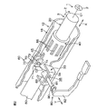
- FIG. 2 is a partially broken schematic perspective view of a main part of the steering device according to the first embodiment, showing a peripheral structure of the lock mechanism.
- FIG. 3A and FIG. 3B are schematic cross-sectional views of the locking mechanism of the first embodiment.
- FIG. 3A shows the time when the operation unit is in the retracted position
- FIG. 3B shows the time when the operation unit is in the operating position.
- FIG. 4 is a schematic cross-sectional view of a main part of the steering apparatus according to the second embodiment of the present invention.
- FIG. 5 is a schematic cross-sectional view of a main part of a steering apparatus according to a third embodiment of the present invention.
- FIG. 1 is a schematic cross-sectional view of a steering apparatus according to a first embodiment of the present invention.
- FIG. 2 is a partially broken schematic perspective view of a main part of the steering device according to
- FIG. 6 is a schematic cross-sectional view of a main part of a steering apparatus according to a fourth embodiment of the present invention.
- FIG. 7 is a cross-sectional view of the peripheral structure of the operation unit in the steering apparatus according to the fifth embodiment of the present invention. It is a perspective view of the slide guide in 5th Embodiment.
- FIG. 1 is a schematic cross-sectional view of a main part of a steering apparatus according to a first embodiment of the present invention.
- a steering apparatus 1 includes a steering shaft 3 having a steering member 2 such as a steering wheel connected to one end thereof, and a rack and pinion mechanism connected to the steering shaft 3 via an intermediate shaft 4.
- the steering mechanism 5 is provided.
- the steering device 1 is configured as an electric power steering device. That is, the steering device 1 includes an assist motor 6 that generates an assist force, and a speed reducer 7 that decelerates and transmits the output rotation of the assist motor 6 to the steering shaft 3.
- the steering device 1 includes a torque sensor 8 that detects a steering torque, and an ECU that controls the assist motor 6 based on the steering torque detected by the torque sensor 8 and the vehicle speed detected by the vehicle speed sensor 9 (assist control). (Electronic Control Unit) 10.
- the steering device 1 includes a hollow steering column 12 that rotatably supports the steering shaft 3 inserted in the axial direction X.
- the steering column 12 is fixed to the vehicle body 11 via brackets B1 and B2.
- the steering column 12 supports the steering shaft 3 through a first bearing 13, a second bearing 14 and a third bearing 15 so as to be rotatable.
- the steering column 12 includes a single-tube hollow jacket 16 and a reduction gear housing 17 that is connected to the lower portion in the axial direction of the jacket 16 and accommodates the reduction gear 7.
- the single tube jacket 16 includes a sensor housing 18 at a lower portion in the axial direction X.
- the sensor housing 18 is expanded by plastic deformation and accommodates the torque sensor 8.
- the torque sensor 8 has an annular shape surrounding the steering shaft 3 and is fitted and held on the inner periphery of the sensor housing 18.
- the output signal of the torque sensor 8 is input to the ECU 10 via the wiring 19.
- the steering shaft 3 includes a column shaft 20 connected to the steering member 2, an input shaft 21 formed integrally with a part of the column shaft 20, an output shaft 22 connected to the intermediate shaft 4, an input shaft 21 and an output shaft 22. Are connected to the same axis.
- the torsion bar 23 is elastically twisted and deformed, whereby the input shaft 21 and the output shaft 22 are relatively rotated.
- the torque sensor 8 detects a steering torque based on the relative rotation between the input shaft 21 and the output shaft 22.
- the column shaft 20 includes a first shaft 40 and a second shaft 50.
- One end 41 of the first shaft 40 is connected to the steering member 2.
- the jacket 16 rotatably supports the first shaft 40 via the first bearing 13.
- a fitting hole 43 extending in the axial direction X from the other end 42 of the first shaft 40 is formed. That is, the first shaft 40 is formed as a hollow shaft in which at least a part of the axial direction X is hollow.
- a plurality of key lock holes 44 into which the lock key LK is fitted by operation of an ignition key (not shown) are formed in the first shaft 40 which is a hollow shaft.
- the key lock holes 44 are long holes extending in the axial direction X, and are arranged at equal intervals in the circumferential direction Z of the first shaft 40.
- the first shaft 40 is formed with an axial slit 45 extending in the axial direction X from the other end 42, whereby the first shaft 40 can be elastically reduced in diameter.
- the first shaft 40 is fitted to the outer periphery of the second shaft 50. Specifically, the upper portion of the second shaft 50 in the axial direction X is spline-fitted with the fitting hole 43 of the first shaft 40. For this reason, the 1st shaft 40 and the 2nd shaft 50 can rotate integrally. Further, the first shaft 40 is movable in the axial direction X with respect to the second shaft 50.
- a male spline is formed on the outer periphery of the second shaft 50 within a predetermined length from the one end 51 in the axial direction X.
- a female spline is formed on the inner periphery of the fitting hole 43 of the first shaft 40.
- the other end 52 (corresponding to the end of the input shaft 21) of the second shaft 50 is fitted to the one end 22a of the output shaft 22 so as to be relatively rotatable.
- One end 23a of the torsion bar 23 is connected to the other end 52 of the second shaft 50 so as to be integrally rotatable.
- the other end 23b of the torsion bar is connected to the other end 22b of the output shaft 22 so as to be integrally rotatable.
- the speed reducer 7 is driven by a drive gear 24 such as a worm shaft that is rotationally driven by the assist motor 6 and a driven gear 24 such as a worm wheel that meshes with the drive gear 24 and is connected to the outer periphery of the output shaft 22 of the steering shaft 3 so as to be integrally rotatable. And a gear 25.
- the reduction gear housing 17 is formed by integrally forming a cylindrical drive gear housing portion 26 for housing and holding the drive gear 24 and a driven gear housing portion 27 for housing and holding the driven gear 25 in a cross shape with a single material. ing.
- the driven gear accommodating portion 27 rotatably supports the output shaft 22 of the steering shaft 3 via the second bearing 14 and the third bearing 15 disposed above and below the driven gear 25 in the axial direction X.
- the driven gear accommodating portion 27 includes a first housing 28 and a second housing 29 that are arranged vertically with respect to the axial direction X and connected to each other.
- the first housing 28 rotatably supports the output shaft 22 via the second bearing 14.
- the second housing 29 rotatably supports the output shaft 22 via the third bearing 15.
- the inner rings of the second bearing 14 and the third bearing 15 are fitted to the output shaft 22 so as to be integrally rotatable.
- the first housing 28 includes an outer cylinder 30 that is press-fitted into the inner periphery of the upper portion of the second housing 29 in the axial direction X, an inner cylinder 31 that holds the outer ring of the second bearing 14 on the inner periphery, and an outer cylinder 30. And a connecting wall 32 that connects the lower ends in the axial direction X of the inner cylinder 31.
- the outer cylinder 30 of the first housing 28 is press-fitted into the inner periphery of the upper part of the second housing 29 in the axial direction X, whereby the inner cylinder 31 of the first housing 28 is reduced in diameter.
- the inner cylinder 31 of the first housing 28 of the speed reducer housing 17 is press-fitted to the lower end portion of the jacket 16 (corresponding to the lower end portion of the sensor housing 18 in the axial direction X).
- the lower end portion of the jacket 16 supports the output shaft 22 via the inner cylinder 31 and the second bearing 14.
- the output shaft 22 supports the lower end portion in the axial direction X of the second shaft 50 of the column shaft 20. Therefore, the lower end portion in the axial direction X of the second shaft 50 is rotatably supported by the jacket 16.
- the steering device 1 includes a lock mechanism 60 that fastens and releases the first shaft 40 and the second shaft 50 in the axial direction X.
- the lock mechanism 60 includes a lock unit 70 and an operation unit 80.
- the lock mechanism 60 further includes a biasing member 90.
- the lock portion 70 is connected to the column shaft 20 of the steering shaft 3 and the central axis C1 of the column shaft 20 so as to be integrally rotatable.
- the lock unit 70 fastens or releases the first shaft 40 and the second shaft 50 in the axial direction X.
- FIG. 3A and 3B are schematic cross-sectional views of the lock mechanism 60.
- FIG. The operation unit 80 is supported by the jacket 16.
- the operation unit 80 is displaceable between an operation position where the lock unit 70 can be operated in a steering neutral state (see FIG. 3B) and a retreat position where the lock unit 70 is retracted from the operation position [see FIG. 3A]. .
- the lock portion 70 avoids interference with the rotation locus RT of the lock portion 70 around the central axis C1 during steering in the state of being in the retracted position of FIG. For this reason, the steering which rotates the steering shaft 3 around the central axis C1 in the state where the lock portion 70 is in the retracted position is allowed.
- the urging member 90 urges the lock portion 70 to the retracted position.
- the lock portion 70 includes a pair of tightening portions that are opposed to the circumferential direction Z of the first shaft 40 across the axial slit 45 in the first shaft 40 (hollow shaft). And fastening shafts 73 that are inserted through the pair of fastening plates 71 and 72 and fasten the pair of fastening plates 71 and 72 along with the rotation around the central axis. As shown in FIG. 3A, an insertion hole 71 a is formed in one tightening plate 71, and a screw hole 72 a is formed in the other tightening plate 72.
- the tightening shaft 73 includes a bolt that is inserted into the insertion hole 71 a of one tightening plate 71 and screwed into the screw hole 72 a of the other tightening plate 72.
- the fastening shaft 73 is provided with an engaging portion 74 (corresponding to a head portion of a bolt) serving as an input portion of the fastening shaft 73 at one end thereof.
- the engaging portion 74 is formed in, for example, a hexagonal cross section.
- the operation unit 80 includes an operation shaft 81 and an operation lever 82.
- the operation shaft 81 and the tightening shaft 73 are disposed on the same axis C2 in the steering neutral state. That is, the central axis of the tightening shaft 73 whose direction changes according to the steering position coincides with the central axis of the operating shaft 81 (the central axis of the operating shaft 81 is constant) in the steering neutral state.
- the operation shaft 81 is rotatable around the central axis (corresponding to the same axis C2) of the operation shaft 81 by the jacket 16, and the direction of the central axis (corresponding to the same axis C2) of the operation shaft 81 (the axis of the operation shaft 81) It is supported so as to be movable in the direction Y).
- a support frame 33 as a support portion is fixed to the outer periphery of the jacket 16.
- the support frame 33 has a support plate 34 that extends parallel to the axial direction X.
- the support plate 34 is formed with a support hole 35 made of a long hole extending in the axial direction X.
- the operation shaft 81 is inserted through the support hole 35.
- the operation shaft 81 and the support hole 35 are relatively movable in the axial direction X.
- the operation lever 82 is fixed to one end of the operation shaft 81.
- the operation lever 82 rotates the operation shaft 81 around the central axis (corresponding to the same axis C2) of the operation shaft 81.
- the engagement portion 83 engages with the engagement portion 74 of the lock portion 70 so as to be integrally rotatable.
- the engaging portion 83 of the operation shaft 81 is configured as a hexagonal hole forming portion that forms a hexagonal hole, for example, and can be fitted to a bolt head that is the engaging portion 74 of the fastening shaft 73.
- the operation procedures when performing telescopic adjustment using the lock mechanism 60 are the following (1) to (6). (1) Return the steering member 2 (steering shaft 3) to the steering neutral position.
- the tightening shaft 73 of the lock unit 70 and the operation shaft 81 of the operation unit 80 in the retracted position are arranged on the same axis C2. That is, the center axis of the fastening shaft 73 is coincident with the center axis of the operating shaft 81, and the engaging portion 83 of the operating shaft 81 and the engaging portion 74 of the fastening shaft 73 face each other on the same axis C2.
- the state is as shown in FIG. (2)
- the operating lever 82 is pushed in the direction of the same axis C2 against the urging member 90 (on the side of the fastening shaft 73 in the axial direction Y of the operating shaft 81), and the operating portion 80 is moved to the retracted position in FIG.
- the engaging portion 83 of the operating shaft 81 is engaged with the engaging portion 74 of the fastening shaft 73 so as to be integrally rotatable.
- the operating lever 82 is rotated around the same axis C2 in the unlocking direction to loosen the fastening shaft 73 made of a bolt.
- the tightening of the first shaft 40 with respect to the second shaft 50 is released, and the first shaft 40 becomes movable in the axial direction X (unlocked).
- the desired telescopic adjustment is performed by moving the first shaft 40 in the axial direction X while maintaining the engaged state of the engaging portions 83 and 74, that is, with the operating portion 80 maintained at the operating position. Move to position.
- the operation lever 82 is rotated in the locking direction around the same axis C2 to tighten the tightening shaft 73 made of a bolt. Accordingly, the first shaft 40 is tightened with respect to the second shaft 50, and the first shaft 40 and the second shaft 50 are coupled and locked in the axial direction X so as not to be relatively movable.
- the operation portion 80 (the operation shaft 81 and the operation lever 82) is retracted to the retracted position in FIG. Thereby, it is possible to perform steering by rotating the steering shaft 3 around the central axis C1.
- the telescopic adjustment can be performed by extending and retracting the steering shaft 3 in a state where the fastening of the first shaft 40 and the second shaft 50 is released by the lock mechanism 60.
- the structure can be simplified by using the single tube jacket 16.
- the structure can be simplified by forming the key lock hole 44 in the first shaft 40 constituting a part of the steering shaft 3.
- the lock mechanism 60 is displaced between a lock portion 70 for fastening / unfastening the first shaft 40 and the second shaft 50 in the axial direction X, and an operation position and a retreat position where the lock portion 70 can be operated in a steering neutral state.
- Possible operation unit 80 The lock unit 70 can be operated by displacing the operation unit 80 to the operation position shown in FIG.
- the operating unit 80 may be retracted to the retracted position illustrated in FIG. 3A so that the operating unit 80 does not interfere with the rotation locus RT of the lock unit 70 during steering and the rotation of the steering shaft 3 is allowed. it can.
- the lock portion 70 includes a pair of fastening plates 71 and 72 facing the circumferential direction Z across the axial slit 45 in the first shaft 40 that is a hollow shaft, and a fastening for fastening the pair of fastening plates 71 and 72. And an attached shaft 73.
- the operation unit 80 includes an operation shaft 81 and an operation lever 82 which are disposed on the same axis C2 as the tightening shaft 73 in the steering neutral state. Therefore, when the operation lever 80 is rotated in a state where the operation portion 80 is displaced to the operation position in the steering neutral state and the engagement portion 83 of the operation portion 80 is engaged with the engagement portion 74 of the fastening shaft 73.
- the rotated tightening shaft 73 tightens the pair of tightening plates 71 and 72 to reduce the diameter of the first shaft 40, or loosens the tightening of the pair of tightening plates 71 and 72 to reduce the first shaft 40. Release the diameter reduction. Thereby, the fastening of the axial direction X of the 1st shaft 40 and the 2nd shaft 50 can be performed.
- FIG. 4 is a cross-sectional view of a main part of a steering device 1P according to the second embodiment of the present invention.
- the steering apparatus 1P according to the second embodiment shown in FIG. 4 is mainly different from the steering apparatus 1 according to the first embodiment shown in FIG. That is, the steering device 1P includes an annular key ring 100 that is provided separately from the first shaft 40P of the column shaft 20P of the steering shaft 3P and surrounds the first shaft 40P. Further, the steering device 1P includes a tolerance ring 110 that is interposed between the outer peripheral surface of the first shaft 40P and the inner peripheral surface of the key ring 100.
- the key ring 100 has key lock holes 101 arranged at equal intervals in the circumferential direction Z.
- the tolerance ring 110 frictionally engages the convex portion of the outer peripheral surface thereof with the inner peripheral surface of the key ring 100 to restrict relative rotation between the first shaft 40P and the key ring 100.
- the outer peripheral surface of the tolerance ring 110 becomes a sliding surface, so that the relative relationship between the first shaft 40P and the key ring 100 is increased. Rotation is allowed. That is, the tolerance ring 110 functions as a torque limiter when an excessive torque is input, and prevents peripheral members from being damaged.
- FIG. 5 is a cross-sectional view of a main part of a steering apparatus 1Q according to the third embodiment of the present invention.
- the steering device 1Q according to the third embodiment shown in FIG. 5 is mainly different from the steering device 1 according to the first embodiment shown in FIG. That is, in the steering device 1Q, the column shaft 20Q of the steering shaft 3Q includes the first shaft 40Q and the second shaft 50Q. One end 41Q in the axial direction X of the first shaft 40Q is connected to the steering member 2. A fitting hole 53 extending in the axial direction X from one end 51Q is formed in the second shaft 50Q. That is, the second shaft 50Q is formed as a hollow shaft in which at least a part of the axial direction X is hollow.
- the second shaft 50Q which is a hollow shaft, forms a plurality of key lock holes 54 that are separated in the circumferential direction Z. Further, the second shaft 50Q is formed with an axial slit 55 extending from the one end 51Q in the axial direction X, whereby the second shaft 50Q can be elastically reduced in diameter.
- the second shaft 50Q is fitted on the outer periphery of the first shaft 40Q. Specifically, the lower portion in the axial direction X of the first shaft 40Q is spline-fitted with the fitting hole 53 of the second shaft 50Q. For this reason, the 1st shaft 40Q and the 2nd shaft 50Q can rotate integrally. Further, the first shaft 40Q is movable in the axial direction X with respect to the second shaft 50Q.
- a male spline is formed on the outer periphery of the first shaft 40Q within a predetermined length from the other end 42Q in the axial direction X.
- a female spline is formed on the inner periphery of the fitting hole 53 of the second shaft 50Q.
- the steering shaft 3Q can be telescopically adjusted by expanding and contracting the steering shaft 3Q in a state where the fastening of the first shaft 40Q and the second shaft 50Q is released. Further, the structure can be simplified by using the single tube jacket 16.
- FIG. 6 is a cross-sectional view of a main part of a steering device 1R according to a fourth embodiment of the present invention.
- the steering device 1R of the fourth embodiment of FIG. 6 is mainly different from the steering device 1Q of the third embodiment of FIG. 5 in the column shaft 20R of the steering shaft 3R in the first shaft 40R and the second shaft 50R. However, it is not spline fitting but frictional engagement via the tolerance ring 110R.
- the tolerance ring 110R is interposed between the lower outer peripheral surface in the axial direction X of the first shaft 40R and the inner peripheral surface of the fitting hole 53R of the second shaft 50R.
- the tolerance ring 110R regulates the relative rotation between the first shaft 40R and the second shaft 50R by frictionally engaging the convex portion of the outer peripheral surface thereof with the inner peripheral surface of the fitting hole 53R of the second shaft 50R. Accordingly, the first shaft 40R and the second shaft 50R can be integrally rotated to be steered.
- the tolerance ring 110R when there is a torque input of a predetermined value or more between the first shaft 40R and the second shaft 50R, the outer peripheral surface of the tolerance ring 110R becomes a sliding surface, so that the first shaft 40R and the second shaft 50R. Relative rotation is allowed. That is, the tolerance ring 110R functions as a torque limiter and suppresses the input of excessive torque to the column shaft 20R to prevent damage to surrounding members.
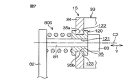
- FIG. 7 is a cross-sectional view of the peripheral structure of the operation unit 80S in the steering device 1S according to the fifth embodiment of the present invention.
- the operation unit 80 ⁇ / b> S includes a slide guide 120 that guides the slide movement of the operation shaft 81 in the axial direction Y with respect to the support hole 35 of the support plate 34.
- the slide guide 120 is formed with an insertion hole 121 through which the operation shaft 81 is movably inserted in the axial direction Y of the operation shaft 81 (the direction of the same axis C2).
- the slide guide 120 is formed with slide grooves 122 and 123 that are slidably fitted in the axial direction X with respect to a pair of edge portions 35a and 35b extending in the axial direction X of the support hole 35, respectively.
- the slide guide 120 By the action of the slide guide 120, the central axis of the operation shaft 81 is maintained in a state orthogonal to the support plate 34, and the tilt of the operation shaft 81 is suppressed.
- the present invention is not limited to the above-described embodiment.
- the slide guide 120 of the fifth embodiment may be applied to the first to fourth embodiments.
- the steering device 1 may be a manual steering device instead of an electric power steering device.
- Various modifications can be made within the scope of the claims of the present invention.
- the structure of the steering device capable of telescopic adjustment can be simplified.
- Lock mechanism 70 Lock parts 71, 72 ... Clamping plate (clamping part) 71a ... Insertion hole 72a ... Screw hole 73 ... Tightening shaft 73a ... Opposing end 74 ... Engaging part 80 ... Operating part 81 ... Operating shaft 81a ... Opposing end part 82 ... Operating lever 83 ... Engaging part 90 ... Energizing member DESCRIPTION OF SYMBOLS 100 ... Key ring 101 ... Key lock hole 110; 110R ... Tolerance ring C2 ... Same axis LK ... Lock key RT ... Rotation locus X ... Axial direction
Landscapes
- Engineering & Computer Science (AREA)
- Chemical & Material Sciences (AREA)
- Combustion & Propulsion (AREA)
- Transportation (AREA)
- Mechanical Engineering (AREA)
- Steering Controls (AREA)
Abstract
【課題】テレスコピック調整可能なステアリング装置において構造を簡素化する。 【解決手段】ステアリング装置1が、ステアリングシャフト3と、単管のジャケット16と、ロック機構60とを備える。ステアリングシャフト3が、軸方向Xに伸縮可能に互いに嵌合された第1シャフト40および第2シャフト50を含む。ジャケット16が、第1シャフト40および第2シャフト50を回転可能に支持し、車体11に支持される。ロック機構60が、第1シャフト40および第2シャフト50を軸方向Xに締結したり、締結解除したりする。
Description
本発明はステアリング装置に関する。
テレスコピック調整機能を持たないステアリング装置において、ステアリングシャフトを単管のジャケットで支持する構造が提案されている(例えば特許文献1)。
一方、テレスコピック調整機能を有するステアリング装置では、通例、ジャケットとして、伸縮可能な嵌合された二重管が用いられている。しかしながら、二重管を用いた場合、構造が複雑になる。
そこで、本発明の目的は、テレスコピック調整可能なステアリング装置において、構造を簡素化することである。
そこで、本発明の目的は、テレスコピック調整可能なステアリング装置において、構造を簡素化することである。
請求項1の発明は、軸方向(X)に伸縮可能に互いに嵌合された第1シャフト(40;40P;40Q;40R)および第2シャフト(50;50Q;50R)を含むステアリングシャフト(3;3P;3Q;3R)と、前記第1シャフトおよび前記第2シャフトを回転可能に支持し車体に支持される単管のジャケット(16)と、前記第1シャフトおよび前記第2シャフトを前記軸方向に締結および締結解除するロック機構(60)と、を備えるステアリング装置(1;1P;1Q;1R)を提供する。
なお、括弧内の英数字は、後述する実施形態における対応構成要素等を表すが、このことは、むろん、本発明がそれらの実施形態に限定されるべきことを意味するものではない。以下、この項において同じ。
請求項2のように、前記第1シャフトおよび前記第2シャフトの一方は、前記第1シャフトおよび前記第2シャフトの他方の外周に嵌合する中空シャフトを含み、前記中空シャフトは、イグニッションキーの操作によってロックキーが嵌合されるキーロック孔(44;54)が形成されて成っていてもよい。
請求項2のように、前記第1シャフトおよび前記第2シャフトの一方は、前記第1シャフトおよび前記第2シャフトの他方の外周に嵌合する中空シャフトを含み、前記中空シャフトは、イグニッションキーの操作によってロックキーが嵌合されるキーロック孔(44;54)が形成されて成っていてもよい。
請求項3のように、前記ロック機構は、前記ステアリングシャフトと一体回転可能に連結されて前記第1シャフトおよび前記第2シャフトを前記軸方向に締結および締結解除するロック部(70)と、前記ジャケットによって支持された操作部(80)を含んでいてもよい。前記操作部は、操舵中立状態で前記ロック部を操作可能な操作位置と操舵時の前記ロック部の回転軌跡との干渉を避けるように前記操作位置から退避する退避位置とに変位可能であってもよい。
請求項4のように、前記第1シャフトおよび前記第2シャフトの一方は、前記第1シャフトおよび前記第2シャフトの他方の外周に嵌合し軸方向スリット(45;55)を形成した中空シャフトを含み、前記ロック部は、前記軸方向スリットを挟んで前記中空シャフトの周方向(Z)に対向する一対の締付部(71,72)と、前記一対の締付部に挿通され回転に伴って前記一対の締付部を締め付けて前記中空シャフトを縮径させる締付軸(73)と、を含み、前記操作部は、前記操舵中立状態で前記締付軸と同一軸線(C2)上に配置されて前記ジャケットによって前記同一軸線の回りに回転可能に且つ前記同一軸線方向に移動可能に支持された操作軸(81)と、前記操作軸に固定され前記操作軸を前記同一軸線の回りに回転させる操作レバー(82)と、を含み、前記操作軸および前記締付軸は、前記操舵中立状態で前記操作部が前記操作位置に変位するときに一体回転可能に係合する一対の係合部(74,83)を含んでいてもよい。
請求項5のように、前記ステアリング装置が前記操作部を前記退避位置に付勢する付勢部材(90)を備えていてもよい。
請求項1の発明では、ロック機構によって第1シャフトおよび第2シャフトの締結を解除した状態で、ステアリングシャフトを伸縮させてテレスコピック調整することができる。また、単管のジャケットを用いることで構造を簡素化することができる。
請求項2の発明では、ステアリングシャフトの一部を構成する中空シャフトに、キーロック孔を形成することにより、構造を簡素化することができる。
請求項2の発明では、ステアリングシャフトの一部を構成する中空シャフトに、キーロック孔を形成することにより、構造を簡素化することができる。
請求項3の発明では、操作部を操作位置に変位させてロック部を操作することができる。また、操作部を退避位置に退避させて、操作部が、操舵時のロック部の回転軌跡と干渉しないようにし、ステアリングシャフトの回転を許容することができる。
請求項4の発明では、操舵中立状態で操作部を操作位置に変位させて、操作部の係合部を締付軸の係合部に係合させた状態で、操作レバーを回転させると、回転された締付軸が、一対の締付部を締め付けて中空シャフトを縮径させたり、一対の側板に対する締め付けを緩めて中空シャフトの縮径を解除したりする。これにより、第1シャフトおよび第2シャフトの締結、締結解除を行うことができる。
請求項4の発明では、操舵中立状態で操作部を操作位置に変位させて、操作部の係合部を締付軸の係合部に係合させた状態で、操作レバーを回転させると、回転された締付軸が、一対の締付部を締め付けて中空シャフトを縮径させたり、一対の側板に対する締め付けを緩めて中空シャフトの縮径を解除したりする。これにより、第1シャフトおよび第2シャフトの締結、締結解除を行うことができる。
請求項5の発明では、操作レバーから手を離すと、付勢部材によって、操作部が、退避位置に自動的に戻される。
以下では、本発明の実施形態を、添付図面を参照して詳細に説明する。
(第1実施形態)
図1は、本発明の第1実施形態のステアリング装置の要部の概略断面図である。図1を参照して、ステアリング装置1は、ステアリングホイール等の操舵部材2が一端に連結されたステアリングシャフト3と、インターミディエイトシャフト4を介してステアリングシャフト3と連結された例えばラックアンドピニオン機構等の転舵機構5とを備える。
(第1実施形態)
図1は、本発明の第1実施形態のステアリング装置の要部の概略断面図である。図1を参照して、ステアリング装置1は、ステアリングホイール等の操舵部材2が一端に連結されたステアリングシャフト3と、インターミディエイトシャフト4を介してステアリングシャフト3と連結された例えばラックアンドピニオン機構等の転舵機構5とを備える。
ステアリング装置1は、電動パワーステアリング装置として構成されている。すなわち、ステアリング装置1は、アシスト力を発生するアシストモータ6と、アシストモータ6の出力回転を減速してステアリングシャフト3に伝達する減速機7とを備える。
また、ステアリング装置1は、操舵トルクを検出するトルクセンサ8と、トルクセンサ8により検出された操舵トルクや車速センサ9により検出された車速に基づいてアシストモータ6を駆動制御(アシスト制御)するECU(Electronic Control Unit)10とを備える。
また、ステアリング装置1は、操舵トルクを検出するトルクセンサ8と、トルクセンサ8により検出された操舵トルクや車速センサ9により検出された車速に基づいてアシストモータ6を駆動制御(アシスト制御)するECU(Electronic Control Unit)10とを備える。
また、ステアリング装置1は、ステアリングシャフト3を軸方向Xに挿通させて回転可能に支持する中空のステアリングコラム12を備える。ステアリングコラム12は、ブラケットB1,B2を介して車体11に固定される。ステアリングコラム12は、第1軸受13、第2軸受14および第3軸受15を介して、ステアリングシャフト3を回転可能に支持している。
ステアリングコラム12は、単管の中空のジャケット16と、ジャケット16の軸方向下部に連結され、減速機7を収容した減速機ハウジング17とを含む。
単管のジャケット16は、軸方向Xの下部にセンサハウジング18を含む。センサハウジング18は、塑性変形により拡管されて、トルクセンサ8を収容している。トルクセンサ8は、ステアリングシャフト3を取り囲む環状をなしており、センサハウジング18の内周に嵌合保持されている。トルクセンサ8の出力信号は、配線19を介してECU10に入力される。
単管のジャケット16は、軸方向Xの下部にセンサハウジング18を含む。センサハウジング18は、塑性変形により拡管されて、トルクセンサ8を収容している。トルクセンサ8は、ステアリングシャフト3を取り囲む環状をなしており、センサハウジング18の内周に嵌合保持されている。トルクセンサ8の出力信号は、配線19を介してECU10に入力される。
ステアリングシャフト3は、操舵部材2に連なるコラムシャフト20と、コラムシャフト20の一部と一体に形成された入力軸21と、インターミディエイトシャフト4に連なる出力軸22と、入力軸21および出力軸22を同一軸線上に連結するトーションバー23とを備えている。
入力軸21に操舵トルクが入力されたときに、トーションバー23が弾性的にねじり変形し、これにより、入力軸21と出力軸22とが相対回転する。トルクセンサ8は、入力軸21と出力軸22との相対回転に基づいて、操舵トルクを検出する。
入力軸21に操舵トルクが入力されたときに、トーションバー23が弾性的にねじり変形し、これにより、入力軸21と出力軸22とが相対回転する。トルクセンサ8は、入力軸21と出力軸22との相対回転に基づいて、操舵トルクを検出する。
コラムシャフト20は、第1シャフト40と、第2シャフト50とを含む。第1シャフト40の一端41は、操舵部材2に連結される。ジャケット16は、第1軸受13を介して、第1シャフト40を回転可能に支持している。第1シャフト40の他端42から軸方向Xに延びる嵌合孔43が形成されている。すなわち、第1シャフト40は、軸方向Xの少なくとも一部が中空とされた中空シャフトとして形成されている。
中空シャフトである第1シャフト40には、イグニッションキー(図示せず)の操作によってロックキーLKが嵌合される複数のキーロック孔44が形成されている。図2に示すように、キーロック孔44は、軸方向Xに延びる長孔からなり、第1シャフト40の周方向Zに等間隔で配置されている。また、第1シャフト40には、他端42から軸方向Xに延びる軸方向スリット45が形成されており、これにより第1シャフト40が弾性的に縮径可能である。
図1に示すように、第1シャフト40は、第2シャフト50の外周に嵌合している。具体的には、第2シャフト50の軸方向Xの上部は、第1シャフト40の嵌合孔43とスプライン嵌合されている。このため、第1シャフト40と第2シャフト50は一体回転可能である。また、第1シャフト40は、第2シャフト50に対して軸方向Xに移動可能である。
第2シャフト50の外周には、軸方向Xの一端51から所定長の範囲に、雄スプラインが形成されている。第1シャフト40の嵌合孔43の内周には、雌スプラインが形成されている。第2シャフト50の他端52(入力軸21の端部に相当)は、出力軸22の一端22aに相対回転可能に嵌合している。
トーションバー23の一端23aは、第2シャフト50の他端52と一体回転可能に連結されている。トーションバーの他端23bは、出力軸22の他端22bと一体回転可能に連結されている。
トーションバー23の一端23aは、第2シャフト50の他端52と一体回転可能に連結されている。トーションバーの他端23bは、出力軸22の他端22bと一体回転可能に連結されている。
減速機7は、アシストモータ6により回転駆動されるウォーム軸等の駆動ギヤ24と、駆動ギヤ24と噛み合い、ステアリングシャフト3の出力軸22の外周に一体回転可能に連結されたウォームホイール等の被動ギヤ25とを備えている。
減速機ハウジング17は、駆動ギヤ24を収容保持する筒状の駆動ギヤ収容部26と、被動ギヤ25を収容保持する被動ギヤ収容部27とを、単一の材料で交差状に一体に形成している。
減速機ハウジング17は、駆動ギヤ24を収容保持する筒状の駆動ギヤ収容部26と、被動ギヤ25を収容保持する被動ギヤ収容部27とを、単一の材料で交差状に一体に形成している。
被動ギヤ収容部27は、軸方向Xに関して被動ギヤ25の上下に配置された第2軸受14および第3軸受15を介して、ステアリングシャフト3の出力軸22を回転可能に支持している。
被動ギヤ収容部27は、軸方向Xに関して上下に配置され互いに連結された第1ハウジング28および第2ハウジング29を含む。第1ハウジング28が、第2軸受14を介して出力軸22を回転可能に支持している。第2ハウジング29が、第3軸受15を介して出力軸22を回転可能に支持している。第2軸受14および第3軸受15の各内輪は、出力軸22に一体回転可能に嵌合されている。
被動ギヤ収容部27は、軸方向Xに関して上下に配置され互いに連結された第1ハウジング28および第2ハウジング29を含む。第1ハウジング28が、第2軸受14を介して出力軸22を回転可能に支持している。第2ハウジング29が、第3軸受15を介して出力軸22を回転可能に支持している。第2軸受14および第3軸受15の各内輪は、出力軸22に一体回転可能に嵌合されている。
第1ハウジング28は、第2ハウジング29の軸方向Xの上部の内周に圧入係合された外筒30と、内周に第2軸受14の外輪を保持する内筒31と、外筒30と内筒31の軸方向Xの下端間を連結する連結壁32とを備えている。
第1ハウジング28の外筒30が、第2ハウジング29の軸方向Xの上部の内周に圧入されることで、第1ハウジング28の内筒31が縮径されている。
第1ハウジング28の外筒30が、第2ハウジング29の軸方向Xの上部の内周に圧入されることで、第1ハウジング28の内筒31が縮径されている。
また、減速機ハウジング17の第1ハウジング28の内筒31が、ジャケット16の下端部(センサハウジング18の軸方向Xの下端部に相当)に圧入嵌合されている。ジャケット16の下端部は、内筒31および第2軸受14を介して出力軸22を支持している。出力軸22によって、コラムシャフト20の第2シャフト50の軸方向Xの下端部が支持されている。したがって、第2シャフト50の軸方向Xの下端部は、ジャケット16によって回転可能に支持されている。
図2に示すように、ステアリング装置1は、第1シャフト40および第2シャフト50を軸方向Xに締結および締結解除するロック機構60を備えている。ロック機構60は、ロック部70と、操作部80とを含む。本実施例では、ロック機構60はさらに付勢部材90を含む。
ロック部70は、ステアリングシャフト3のコラムシャフト20とコラムシャフト20の中心軸線C1の回りに一体回転可能に連結されている。ロック部70は、第1シャフト40および第2シャフト50を軸方向Xに締結したり締結解除したりする。
ロック部70は、ステアリングシャフト3のコラムシャフト20とコラムシャフト20の中心軸線C1の回りに一体回転可能に連結されている。ロック部70は、第1シャフト40および第2シャフト50を軸方向Xに締結したり締結解除したりする。
図3(a)および図3(b)は、ロック機構60の概略断面図である。操作部80は、ジャケット16によって支持されている。操作部80は、ロック部70を操舵中立状態で操作可能な操作位置[図3(b)参照]と、前記操作位置から退避する退避位置[図3(a)参照]とに変位可能である。
ロック部70は、図3(a)の退避位置にある状態で、操舵時の中心軸線C1回りのロック部70の回転軌跡RTとの干渉を避ける。このため、ロック部70が退避位置にある状態で、ステアリングシャフト3を中心軸線C1回りに回転させる操舵が許容される。付勢部材90は、ロック部70を前記退避位置に付勢している。
ロック部70は、図3(a)の退避位置にある状態で、操舵時の中心軸線C1回りのロック部70の回転軌跡RTとの干渉を避ける。このため、ロック部70が退避位置にある状態で、ステアリングシャフト3を中心軸線C1回りに回転させる操舵が許容される。付勢部材90は、ロック部70を前記退避位置に付勢している。
図2および図3(a)に示すように、ロック部70は、第1シャフト40(中空シャフト)において軸方向スリット45を挟んで第1シャフト40の周方向Zに対向する一対の締付部としての締付板71,72と、一対の締付板71,72に挿通されその中心軸線回りの回転に伴って一対の締付板71,72を締め付ける締付軸73とを含む。
図3(a)に示すように、一方の締付板71に挿通孔71aが形成され、他方の締付板72にねじ孔72aが形成されている。締付軸73は、一方の締付板71の挿通孔71aに挿通され他方の締付板72のねじ孔72aにねじ込まれたボルトからなる。締付軸73は、その一端に、締付軸73の入力部となる係合部74(ボルトの頭部に相当)を備えている。係合部74は、例えば断面六角形形状に形成されている。
図3(a)に示すように、一方の締付板71に挿通孔71aが形成され、他方の締付板72にねじ孔72aが形成されている。締付軸73は、一方の締付板71の挿通孔71aに挿通され他方の締付板72のねじ孔72aにねじ込まれたボルトからなる。締付軸73は、その一端に、締付軸73の入力部となる係合部74(ボルトの頭部に相当)を備えている。係合部74は、例えば断面六角形形状に形成されている。
操作部80は、操作軸81と、操作レバー82とを含む。操作軸81と締付軸73とは、操舵中立状態で同一軸線C2上に配置される。すなわち、操舵位置に応じて向きが変化する締付軸73の中心軸線が、操舵中立状態で、操作軸81の中心軸線(操作軸81の中心軸線は位置一定)と一致される。操作軸81は、ジャケット16によって操作軸81の中心軸線(同一軸線C2に相当)の回りに回転可能に、且つ操作軸81の中心軸線(同一軸線C2に相当)の方向(操作軸81の軸方向Y)に移動可能に支持されている。
ジャケット16の外周に、支持部としての支持フレーム33が固定されている。支持フレーム33は、軸方向Xと平行に延びる支持板34を有している。支持板34には、軸方向Xに延びる長孔からなる支持孔35が形成されている。
操作軸81は、支持孔35に挿通されている。操作軸81と支持孔35とは、軸方向Xに相対移動可能である。操作レバー82は、操作軸81の一端に固定されている。操作レバー82は、操作軸81を操作軸81の中心軸線(同一軸線C2に相当)の回りに回転させる。
操作軸81は、支持孔35に挿通されている。操作軸81と支持孔35とは、軸方向Xに相対移動可能である。操作レバー82は、操作軸81の一端に固定されている。操作レバー82は、操作軸81を操作軸81の中心軸線(同一軸線C2に相当)の回りに回転させる。
操作軸81の他端には、操作部80が図3(b)に示すように前記操作位置に変位するときにロック部70の係合部74と一体回転可能に係合する係合部83を含む。操作軸81の係合部83は、例えば六角穴を形成する六角穴形成部として構成されており、締付軸73の係合部74であるボルト頭部に嵌合可能である。
ロック機構60を用いてテレスコ調整するときの操作手順は、下記の(1)~(6)である。(1)操舵部材2(ステアリングシャフト3)を操舵中立位置に戻す。これにより、ロック部70の締付軸73と退避位置にある操作部80の操作軸81とが、同一軸線C2上に配置される。すなわち、締付軸73の中心軸線が操作軸81の中心軸線と一致されて、操作軸81の係合部83と締付軸73の係合部74とが、同一軸線C2上で対向する状態[図3(a)の状態]となる。(2)付勢部材90に抗して操作レバー82を同一軸線C2の方向(操作軸81の軸方向Yの締付軸73側)へ押し、操作部80を図3(a)の退避位置から図3(b)の操作位置に変位させて、操作軸81の係合部83を締付軸73の係合部74に一体回転可能に係合させる。(3)両係合部83,74の係合状態で操作レバー82を同一軸線C2の回りにロック解除方向に回転させて、ボルトからなる締付軸73を緩める。これにより、第2シャフト50に対する第1シャフト40の締付が解除され、第1シャフト40が軸方向Xに移動可能な状態となる(ロック解除される)。(4)両係合部83,74の係合状態を維持したままで、すなわち操作部80を操作位置に維持したままで、第1シャフト40を軸方向Xに移動させて、所望のテレスコピック調整位置に移動させる。(5)テレスコピック調整後に、操作レバー82を同一軸線C2の回りにロック方向に回転させて、ボルトからなる締付軸73を締め付ける。これにより、第2シャフト50に対して第1シャフト40が締め付けられ、第1シャフト40および第2シャフト50が、軸方向Xに相対移動不能に連結されてロックされる。(6)操作レバー82から手を離すと、付勢部材90の働きで、操作部80(操作軸81および操作レバー82)が図3(a)の退避位置に退避する。これにより、ステアリングシャフト3を中心軸線C1回りに回転させる操舵が可能となる。
ロック機構60を用いてテレスコ調整するときの操作手順は、下記の(1)~(6)である。(1)操舵部材2(ステアリングシャフト3)を操舵中立位置に戻す。これにより、ロック部70の締付軸73と退避位置にある操作部80の操作軸81とが、同一軸線C2上に配置される。すなわち、締付軸73の中心軸線が操作軸81の中心軸線と一致されて、操作軸81の係合部83と締付軸73の係合部74とが、同一軸線C2上で対向する状態[図3(a)の状態]となる。(2)付勢部材90に抗して操作レバー82を同一軸線C2の方向(操作軸81の軸方向Yの締付軸73側)へ押し、操作部80を図3(a)の退避位置から図3(b)の操作位置に変位させて、操作軸81の係合部83を締付軸73の係合部74に一体回転可能に係合させる。(3)両係合部83,74の係合状態で操作レバー82を同一軸線C2の回りにロック解除方向に回転させて、ボルトからなる締付軸73を緩める。これにより、第2シャフト50に対する第1シャフト40の締付が解除され、第1シャフト40が軸方向Xに移動可能な状態となる(ロック解除される)。(4)両係合部83,74の係合状態を維持したままで、すなわち操作部80を操作位置に維持したままで、第1シャフト40を軸方向Xに移動させて、所望のテレスコピック調整位置に移動させる。(5)テレスコピック調整後に、操作レバー82を同一軸線C2の回りにロック方向に回転させて、ボルトからなる締付軸73を締め付ける。これにより、第2シャフト50に対して第1シャフト40が締め付けられ、第1シャフト40および第2シャフト50が、軸方向Xに相対移動不能に連結されてロックされる。(6)操作レバー82から手を離すと、付勢部材90の働きで、操作部80(操作軸81および操作レバー82)が図3(a)の退避位置に退避する。これにより、ステアリングシャフト3を中心軸線C1回りに回転させる操舵が可能となる。
本実施形態によれば、ロック機構60によって第1シャフト40および第2シャフト50の締結を解除した状態で、ステアリングシャフト3を伸縮させてテレスコピック調整することができる。また、単管のジャケット16を用いることで構造を簡素化することができる。
また、ステアリングシャフト3の一部を構成する第1シャフト40に、キーロック孔44を形成することにより、構造を簡素化することができる。
また、ステアリングシャフト3の一部を構成する第1シャフト40に、キーロック孔44を形成することにより、構造を簡素化することができる。
また、ロック機構60が、第1シャフト40および第2シャフト50を軸方向Xに締結/締結解除するロック部70と、ロック部70を操舵中立状態で操作可能な操作位置と退避位置とに変位可能な操作部80とを含む。操作部80を操舵中立状態で図3(b)の操作位置に変位させてロック部70を操作することができる。また、操作部80を図3(a)の退避位置に退避させて、操作部80が、操舵時のロック部70の回転軌跡RTと干渉しないようにし、ステアリングシャフト3の回転を許容することができる。
また、ロック部70が、中空シャフトである第1シャフト40において軸方向スリット45を挟んで周方向Zに対向する一対の締付板71,72と、一対の締付板71,72を締め付ける締付軸73とを含む。操作部80が、操舵中立状態で締付軸73と同一軸線C2上に配置される操作軸81と、操作レバー82とを含む。
したがって、操作部80を操舵中立状態で操作位置に変位させて、操作部80の係合部83を締付軸73の係合部74に係合させた状態で、操作レバー82を回転させると、回転された締付軸73が、一対の締付板71,72を締め付けて第1シャフト40を縮径させたり、一対の締付板71,72に対する締付を緩めて第1シャフト40の縮径を解除したりする。これにより、第1シャフト40および第2シャフト50の軸方向Xの締結、締結解除を行うことができる。
したがって、操作部80を操舵中立状態で操作位置に変位させて、操作部80の係合部83を締付軸73の係合部74に係合させた状態で、操作レバー82を回転させると、回転された締付軸73が、一対の締付板71,72を締め付けて第1シャフト40を縮径させたり、一対の締付板71,72に対する締付を緩めて第1シャフト40の縮径を解除したりする。これにより、第1シャフト40および第2シャフト50の軸方向Xの締結、締結解除を行うことができる。
また、操作部80が図3(b)の操作位置にある状態で操作レバー82から手を離すと、付勢部材90によって、操作部80が、図3(a)の退避位置に自動的に戻される。
(第2実施形態)
図4は本発明の第2実施形態のステアリング装置1Pの要部の断面図である。
図4の第2実施形態のステアリング装置1Pが、図1の第1実施形態のステアリング装置1と主に異なるのは、下記である。すなわち、ステアリング装置1Pは、ステアリングシャフト3Pのコラムシャフト20Pの第1シャフト40Pとは別体で設けられて第1シャフト40Pを取り囲む環状のキーリング100を備えている。また、ステアリング装置1Pは、第1シャフト40Pの外周面とキーリング100の内周面との間に介在するトレランスリング110を備えている。
(第2実施形態)
図4は本発明の第2実施形態のステアリング装置1Pの要部の断面図である。
図4の第2実施形態のステアリング装置1Pが、図1の第1実施形態のステアリング装置1と主に異なるのは、下記である。すなわち、ステアリング装置1Pは、ステアリングシャフト3Pのコラムシャフト20Pの第1シャフト40Pとは別体で設けられて第1シャフト40Pを取り囲む環状のキーリング100を備えている。また、ステアリング装置1Pは、第1シャフト40Pの外周面とキーリング100の内周面との間に介在するトレランスリング110を備えている。
キーリング100は、周方向Zに等間隔で配置されたキーロック孔101を有している。トレランスリング110は、その外周面の凸部をキーリング100の内周面に摩擦係合させて、第1シャフト40Pとキーリング100との相対回転を規制する。
また、第1シャフト40Pとキーリング100との間に、所定値以上のトルク入力がある場合には、トレランスリング110の外周面が滑り面となることにより、第1シャフト40Pとキーリング100との相対回転が許容される。すなわち、トレランスリング110は過大トルク入力時のトルクリミッタとして機能し、周辺の部材の破損を防止する。
また、第1シャフト40Pとキーリング100との間に、所定値以上のトルク入力がある場合には、トレランスリング110の外周面が滑り面となることにより、第1シャフト40Pとキーリング100との相対回転が許容される。すなわち、トレランスリング110は過大トルク入力時のトルクリミッタとして機能し、周辺の部材の破損を防止する。
図4の第2実施形態の構成要素において、図1の第1実施形態の構成要素と同じ構成要素には、図1の第1実施形態の構成要素の参照符号と同じ参照符号を付してある。第2実施形態によれば、第1シャフト40Pおよび第2シャフト50の締結を解除した状態で、ステアリングシャフト3Pを伸縮させてテレスコピック調整することができる。また、単管のジャケット16を用いることで構造を簡素化することができる。
(第3実施形態)
図5は本発明の第3実施形態のステアリング装置1Qの要部の断面図である。
(第3実施形態)
図5は本発明の第3実施形態のステアリング装置1Qの要部の断面図である。
図5の第3実施形態のステアリング装置1Qが、図1の第1実施形態のステアリング装置1と主に異なるのは、下記である。すなわち、ステアリング装置1Qにおいて、ステアリングシャフト3Qのコラムシャフト20Qが、第1シャフト40Qと、第2シャフト50Qとを含む。
第1シャフト40Qの軸方向Xの一端41Qが、操舵部材2に連結される。第2シャフト50Qには、その一端51Qから軸方向Xに延びる嵌合孔53が形成されている。すなわち、第2シャフト50Qは、軸方向Xの少なくとも一部が中空とされた中空シャフトとして形成されている。
第1シャフト40Qの軸方向Xの一端41Qが、操舵部材2に連結される。第2シャフト50Qには、その一端51Qから軸方向Xに延びる嵌合孔53が形成されている。すなわち、第2シャフト50Qは、軸方向Xの少なくとも一部が中空とされた中空シャフトとして形成されている。
中空シャフトである第2シャフト50Qは、周方向Zに離隔する複数のキーロック孔54を形成している。また、第2シャフト50Qには、一端51Qから軸方向Xに延びる軸方向スリット55が形成されており、これにより第2シャフト50Qは弾性的に縮径可能である。
第2シャフト50Qは、第1シャフト40Qの外周に嵌合している。具体的には、第1シャフト40Qの軸方向Xの下部が、第2シャフト50Qの嵌合孔53とスプライン嵌合されている。このため、第1シャフト40Qと第2シャフト50Qは、一体回転可能である。また、第1シャフト40Qは、第2シャフト50Qに対して軸方向Xに移動可能である。
第2シャフト50Qは、第1シャフト40Qの外周に嵌合している。具体的には、第1シャフト40Qの軸方向Xの下部が、第2シャフト50Qの嵌合孔53とスプライン嵌合されている。このため、第1シャフト40Qと第2シャフト50Qは、一体回転可能である。また、第1シャフト40Qは、第2シャフト50Qに対して軸方向Xに移動可能である。
第1シャフト40Qの外周には、軸方向Xの他端42Qから所定長の範囲に、雄スプラインが形成されている。第2シャフト50Qの嵌合孔53の内周には、雌スプラインが形成されている。
図5の第3実施形態の構成要素において、図1の第1実施形態の構成要素と同じ構成要素には、図1の第1実施形態の構成要素の参照符号と同じ参照符号を付してある。第3実施形態によれば、第1シャフト40Qおよび第2シャフト50Qの締結を解除した状態で、ステアリングシャフト3Qを伸縮させてテレスコピック調整することができる。また、単管のジャケット16を用いることで構造を簡素化することができる。また、テレスコ調整時に締付軸73が軸方向Xに不動となるので、支持孔35および支持板34を軸方向Xに小型化することができる。
(第4実施形態)
図6は本発明の第4実施形態のステアリング装置1Rの要部の断面図である。
図5の第3実施形態の構成要素において、図1の第1実施形態の構成要素と同じ構成要素には、図1の第1実施形態の構成要素の参照符号と同じ参照符号を付してある。第3実施形態によれば、第1シャフト40Qおよび第2シャフト50Qの締結を解除した状態で、ステアリングシャフト3Qを伸縮させてテレスコピック調整することができる。また、単管のジャケット16を用いることで構造を簡素化することができる。また、テレスコ調整時に締付軸73が軸方向Xに不動となるので、支持孔35および支持板34を軸方向Xに小型化することができる。
(第4実施形態)
図6は本発明の第4実施形態のステアリング装置1Rの要部の断面図である。
図6の第4実施形態のステアリング装置1Rが、図5の第3実施形態のステアリング装置1Qと主に異なるのは、ステアリングシャフト3Rのコラムシャフト20Rにおいて、第1シャフト40Rと第2シャフト50Rとが、スプライン嵌合ではなく、トレランスリング110Rを介して摩擦係合されている点である。
トレランスリング110Rは、第1シャフト40Rの軸方向Xの下部の外周面と、第2シャフト50Rの嵌合孔53Rの内周面との間に介在している。トレランスリング110Rは、その外周面の凸部を第2シャフト50Rの嵌合孔53Rの内周面に摩擦係合させて、第1シャフト40Rと第2シャフト50Rとの相対回転を規制する。これにより、第1シャフト40Rと第2シャフト50Rを一体回転させて、操舵が可能である。
トレランスリング110Rは、第1シャフト40Rの軸方向Xの下部の外周面と、第2シャフト50Rの嵌合孔53Rの内周面との間に介在している。トレランスリング110Rは、その外周面の凸部を第2シャフト50Rの嵌合孔53Rの内周面に摩擦係合させて、第1シャフト40Rと第2シャフト50Rとの相対回転を規制する。これにより、第1シャフト40Rと第2シャフト50Rを一体回転させて、操舵が可能である。
また、第1シャフト40Rと第2シャフト50Rとの間に、所定値以上のトルク入力がある場合には、トレランスリング110Rの外周面が滑り面となることにより第1シャフト40Rと第2シャフト50Rとの相対回転が許容される。すなわち、トレランスリング110Rは、トルクリミッタとして機能し、コラムシャフト20Rへの過大トルクの入力を抑制して周辺の部材の破損を防止する。
図6の第4実施形態の構成要素において、図5の第3実施形態の構成要素と同じ構成要素には、図5の第3実施形態の構成要素の参照符号と同じ参照符号を付してある。第4実施形態によれば、第1シャフト40Rおよび第2シャフト50Rの締結を解除した状態で、ステアリングシャフト3Rを伸縮させてテレスコピック調整することができる。また、単管のジャケット16を用いることで構造を簡素化することができる。
(第5実施形態)
図7は、本発明の第5実施形態のステアリング装置1Sにおける操作部80Sの周辺構造の断面図である。
(第5実施形態)
図7は、本発明の第5実施形態のステアリング装置1Sにおける操作部80Sの周辺構造の断面図である。
操作部80Sは、支持板34の支持孔35に対して、操作軸81の軸方向Yへのスライド移動を案内するスライドガイド120を有している。
図8に示すように、スライドガイド120には、操作軸81を操作軸81の軸方向Y(同一軸線C2の方向)に移動可能に挿通させる挿通孔121が形成されている。スライドガイド120には、支持孔35の軸方向Xに延びる一対の縁部35a,35bに対して、軸方向Xにスライド可能にそれぞれ嵌合するスライド溝122,123が形成されている。
図8に示すように、スライドガイド120には、操作軸81を操作軸81の軸方向Y(同一軸線C2の方向)に移動可能に挿通させる挿通孔121が形成されている。スライドガイド120には、支持孔35の軸方向Xに延びる一対の縁部35a,35bに対して、軸方向Xにスライド可能にそれぞれ嵌合するスライド溝122,123が形成されている。
スライドガイド120の働きで、操作軸81の中心軸線が、支持板34に対して直交する状態に維持されて、操作軸81の倒れが抑制される。
本発明は前記実施形態に限定されるものではなく、例えば、第5実施形態のスライドガイド120を第1~第4実施形態に適用してもよい。ステアリング装置1は、電動パワーステアリング装置ではなくて、マニュアルステアリング装置であってもよい。本発明の請求の範囲記載の範囲内で種々の変更を施すことができる。
本発明は前記実施形態に限定されるものではなく、例えば、第5実施形態のスライドガイド120を第1~第4実施形態に適用してもよい。ステアリング装置1は、電動パワーステアリング装置ではなくて、マニュアルステアリング装置であってもよい。本発明の請求の範囲記載の範囲内で種々の変更を施すことができる。
本発明によれば、テレスコピック調整可能なステアリング装置の構造を簡素化することができる。
1;1P;1Q;1R…ステアリング装置
2…操舵部材
3;3P;3Q;3R…ステアリングシャフト
11…車体
12…ステアリングコラム
13…第1軸受
14…第2軸受
15…第3軸受
16…ジャケット
20;20P;20Q;20R…コラムシャフト
21…入力軸
22…出力軸
23…トーションバー
28…第1ハウジング
29…第2ハウジング
33…支持フレーム
34…支持板
35…支持孔
40;40P;40Q;40R…第1シャフト
41;41Q…一端
42;42Q…他端
43…嵌合孔
44…キーロック孔
45…軸方向スリット
50;50Q;50R…第1シャフト
51;51Q…一端
52…他端
53;53R…嵌合孔
54…キーロック孔
55…軸方向スリット
60…ロック機構
70…ロック部
71,72…締付板(締付部)
71a…挿通孔
72a…ねじ孔
73…締付軸
73a…対向端部
74…係合部
80…操作部
81…操作軸
81a…対向端部
82…操作レバー
83…係合部
90…付勢部材
100…キーリング
101…キーロック孔
110;110R…トレランスリング
C2…同一軸線
LK…ロックキー
RT…回転軌跡
X…軸方向
2…操舵部材
3;3P;3Q;3R…ステアリングシャフト
11…車体
12…ステアリングコラム
13…第1軸受
14…第2軸受
15…第3軸受
16…ジャケット
20;20P;20Q;20R…コラムシャフト
21…入力軸
22…出力軸
23…トーションバー
28…第1ハウジング
29…第2ハウジング
33…支持フレーム
34…支持板
35…支持孔
40;40P;40Q;40R…第1シャフト
41;41Q…一端
42;42Q…他端
43…嵌合孔
44…キーロック孔
45…軸方向スリット
50;50Q;50R…第1シャフト
51;51Q…一端
52…他端
53;53R…嵌合孔
54…キーロック孔
55…軸方向スリット
60…ロック機構
70…ロック部
71,72…締付板(締付部)
71a…挿通孔
72a…ねじ孔
73…締付軸
73a…対向端部
74…係合部
80…操作部
81…操作軸
81a…対向端部
82…操作レバー
83…係合部
90…付勢部材
100…キーリング
101…キーロック孔
110;110R…トレランスリング
C2…同一軸線
LK…ロックキー
RT…回転軌跡
X…軸方向
Claims (5)
- ステアリング装置であって、
軸方向に伸縮可能に互いに嵌合された、第1シャフトおよび第2シャフトを含むステアリングシャフトと、
前記第1シャフトおよび前記第2シャフトを回転可能に支持し車体に支持される単管のジャケットと、
前記第1シャフトおよび前記第2シャフトを前記軸方向に締結および締結解除するロック機構と、を備える。 - 請求項1のステアリング装置であって、
前記第1シャフトおよび前記第2シャフトの一方は、前記第1シャフトおよび前記第2シャフトの他方の外周に嵌合する中空シャフトを含み、
前記中空シャフトは、イグニッションキーの操作によってロックキーが嵌合されるキーロック孔が形成されて成る。 - 請求項1または2のステアリング装置であって、
前記ロック機構は、前記ステアリングシャフトと一体回転可能に連結されて前記第1シャフトおよび前記第2シャフトを前記軸方向に締結および締結解除するロック部と、前記ジャケットによって支持された操作部を含み、
前記操作部は、操舵中立状態で前記ロック部を操作可能な操作位置と、操舵時の前記ロック部の回転軌跡との干渉を避けるように前記操作位置から退避する退避位置と、に変位可能である。 - 請求項3のステアリング装置であって、
前記第1シャフトおよび前記第2シャフトの一方は、前記第1シャフトおよび前記第2シャフトの他方の外周に嵌合し軸方向スリットを形成した中空シャフトを含み、
前記ロック部は、前記軸方向スリットを挟んで前記中空シャフトの周方向に対向する一対の締付部と、前記一対の締付部に挿通され回転に伴って前記一対の締付部を締め付けて前記中空シャフトを縮径させる締付軸と、を含み、
前記操作部は、前記操舵中立状態で前記締付軸と同一軸線上に配置されて前記ジャケットによって前記同一軸線の回りに回転可能に且つ前記同一軸線方向に移動可能に支持された操作軸と、前記操作軸に固定され前記操作軸を前記同一軸線の回りに回転させる操作レバーと、を含み、
前記操作軸および前記締付軸は、前記操舵中立状態で前記操作部が前記操作位置に変位するときに一体回転可能に係合する一対の係合部を含む。 - 請求項3または4のステアリング装置であって、
前記操作部を前記退避位置に付勢する付勢部材をさらに備える。
Applications Claiming Priority (2)
| Application Number | Priority Date | Filing Date | Title |
|---|---|---|---|
| JP2015170722A JP2017047730A (ja) | 2015-08-31 | 2015-08-31 | ステアリング装置 |
| JP2015-170722 | 2015-08-31 |
Publications (1)
| Publication Number | Publication Date |
|---|---|
| WO2017038280A1 true WO2017038280A1 (ja) | 2017-03-09 |
Family
ID=58187354
Family Applications (1)
| Application Number | Title | Priority Date | Filing Date |
|---|---|---|---|
| PCT/JP2016/071132 Ceased WO2017038280A1 (ja) | 2015-08-31 | 2016-07-19 | ステアリング装置 |
Country Status (2)
| Country | Link |
|---|---|
| JP (1) | JP2017047730A (ja) |
| WO (1) | WO2017038280A1 (ja) |
Cited By (1)
| Publication number | Priority date | Publication date | Assignee | Title |
|---|---|---|---|---|
| US11345387B2 (en) * | 2019-11-21 | 2022-05-31 | Nsk Ltd. | Electrically adjustable steering |
Citations (4)
| Publication number | Priority date | Publication date | Assignee | Title |
|---|---|---|---|---|
| US2075110A (en) * | 1935-03-19 | 1937-03-30 | Eugene S Starrett | Extensible steering wheel post |
| JPS571763U (ja) * | 1980-06-05 | 1982-01-06 | ||
| JPS6182862U (ja) * | 1984-11-06 | 1986-05-31 | ||
| JPH04124582U (ja) * | 1991-04-30 | 1992-11-13 | 豊田合成株式会社 | テレスコピツク機構を備えたステアリング装置 |
-
2015
- 2015-08-31 JP JP2015170722A patent/JP2017047730A/ja active Pending
-
2016
- 2016-07-19 WO PCT/JP2016/071132 patent/WO2017038280A1/ja not_active Ceased
Patent Citations (4)
| Publication number | Priority date | Publication date | Assignee | Title |
|---|---|---|---|---|
| US2075110A (en) * | 1935-03-19 | 1937-03-30 | Eugene S Starrett | Extensible steering wheel post |
| JPS571763U (ja) * | 1980-06-05 | 1982-01-06 | ||
| JPS6182862U (ja) * | 1984-11-06 | 1986-05-31 | ||
| JPH04124582U (ja) * | 1991-04-30 | 1992-11-13 | 豊田合成株式会社 | テレスコピツク機構を備えたステアリング装置 |
Cited By (1)
| Publication number | Priority date | Publication date | Assignee | Title |
|---|---|---|---|---|
| US11345387B2 (en) * | 2019-11-21 | 2022-05-31 | Nsk Ltd. | Electrically adjustable steering |
Also Published As
| Publication number | Publication date |
|---|---|
| JP2017047730A (ja) | 2017-03-09 |
Similar Documents
| Publication | Publication Date | Title |
|---|---|---|
| JP6508518B2 (ja) | ステアリング装置 | |
| CN102448796B (zh) | 转向装置 | |
| JP2015157502A (ja) | ステアリング装置 | |
| JP6344606B2 (ja) | ステアリング装置 | |
| JP6270140B2 (ja) | ステアリング装置 | |
| EP2602170B1 (en) | Steering apparatus | |
| WO2012165454A1 (ja) | ステアリング装置 | |
| WO2005023622A1 (ja) | テレスコピック機構付衝撃吸収式ステアリングコラム装置 | |
| JP2016165933A (ja) | ステアリング装置 | |
| JP6504391B2 (ja) | ステアリング装置 | |
| EP2666700B1 (en) | Steering device | |
| JP5176349B2 (ja) | ステアリング装置 | |
| JP2017047730A (ja) | ステアリング装置 | |
| CN112550441A (zh) | 用于转向辅助系统的锁定机构 | |
| JP4075676B2 (ja) | 伸縮自在シャフトおよびその製造方法 | |
| JP6558574B2 (ja) | ステアリング装置 | |
| JP2012112416A (ja) | 伸縮可能シャフトおよび車両用操舵装置 | |
| JP4029761B2 (ja) | 伸縮自在シャフトおよびその製造方法 | |
| JP5233246B2 (ja) | 電動テレスコ調整式ステアリング装置 | |
| JP6826754B2 (ja) | ステアリング装置 | |
| JP5440519B2 (ja) | ステアリング装置 | |
| JP4952099B2 (ja) | ロック機構 | |
| JP2013047100A (ja) | ステアリング装置 | |
| JP2009143390A (ja) | 車両の操舵装置 | |
| JP2015143081A (ja) | ステアリング装置 |
Legal Events
| Date | Code | Title | Description |
|---|---|---|---|
| 121 | Ep: the epo has been informed by wipo that ep was designated in this application |
Ref document number: 16841312 Country of ref document: EP Kind code of ref document: A1 |
|
| NENP | Non-entry into the national phase |
Ref country code: DE |
|
| 122 | Ep: pct application non-entry in european phase |
Ref document number: 16841312 Country of ref document: EP Kind code of ref document: A1 |