WO2017038140A1 - 観察用窓部材、観察用窓部材を備えた観察装置、圧力容器、配管、濁度計、及び観察用窓部材の製造方法 - Google Patents
観察用窓部材、観察用窓部材を備えた観察装置、圧力容器、配管、濁度計、及び観察用窓部材の製造方法 Download PDFInfo
- Publication number
- WO2017038140A1 WO2017038140A1 PCT/JP2016/060596 JP2016060596W WO2017038140A1 WO 2017038140 A1 WO2017038140 A1 WO 2017038140A1 JP 2016060596 W JP2016060596 W JP 2016060596W WO 2017038140 A1 WO2017038140 A1 WO 2017038140A1
- Authority
- WO
- WIPO (PCT)
- Prior art keywords
- window member
- observation
- flange
- metal layer
- alloy
- Prior art date
- Legal status (The legal status is an assumption and is not a legal conclusion. Google has not performed a legal analysis and makes no representation as to the accuracy of the status listed.)
- Ceased
Links
Images




Classifications
-
- G—PHYSICS
- G01—MEASURING; TESTING
- G01N—INVESTIGATING OR ANALYSING MATERIALS BY DETERMINING THEIR CHEMICAL OR PHYSICAL PROPERTIES
- G01N21/00—Investigating or analysing materials by the use of optical means, i.e. using sub-millimetre waves, infrared, visible or ultraviolet light
- G01N21/01—Arrangements or apparatus for facilitating the optical investigation
- G01N21/03—Cuvette constructions
Definitions
- the present invention relates to an observation window member, an observation device provided with the observation window member, a pressure vessel, piping, a turbidimeter, and a method for manufacturing the observation window member.
- Patent Document 1 proposes a window member with a seal mechanism that can withstand high temperatures, high pressures, and highly corrosive environments in order to observe the inside of an experimental cell such as supercritical water or supercritical carbon dioxide. .
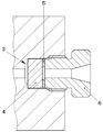
- FIG. 10 is a schematic cross-sectional view showing the structure of the window member with a seal mechanism of Patent Document 1.
- a seal packing 3, a window member 4, a washer 5, and a press fitting 6 are tightened as a window member with a seal mechanism in an opening region of a box 1 of a container that has a high temperature and high pressure inside. It is attached.
- a screw groove is formed in the lower part of the pressing metal 6.
- Such a conventional technique requires the seal packing 3, the washer 5, and the press fitting 6 as the sealing mechanism of the window member 4, and the number of parts increases, so that the manufacturing cost of the observation window member increases. Also, due to the large number of parts, when changing specifications such as changing the size of the window member, it is necessary to change the size of each member as well, and the observation window member is used for various devices and containers. Therefore, it is not easy to change the specifications, and it is difficult to meet market demands.
- the present invention has been made in view of the above problems, and has an observation window member that has a small number of parts, can be easily replaced, and can prevent the window member from being damaged during the replacement. It aims at providing the manufacturing method of an apparatus, a pressure vessel, piping, a turbidimeter, and a window member for observation.
- an observation window member includes two objects to be joined, a flange and a window member, and a first metal layer is formed on one surface of the flange, A second metal layer is formed on one surface facing the flange, a bonding layer is formed in contact with the first metal layer and the second metal layer, and the flange and the window member are Bonded through a bonding layer, the flange is formed of any one of stainless steel, iron, aluminum, an alloy containing iron or aluminum, an alloy of iron and nickel, an alloy of iron, nickel and cobalt, and the window member , Sapphire or diamond, and the first metal layer and the second metal layer are made of titanium, chromium, nickel, vanadium, zirconium, niobium, tantalum, scandium, molybdenum, tan It is formed of any one of stainless steel, hafnium, an alloy thereof, or a laminated film including at least one of them, and the bonding layer is formed of any of
- the flange and the window member are formed by forming the first and second metal layers on the flange and the window member, and forming the bonding layer in contact with the first and second metal layers.
- the number of parts can be reduced because of the bonding, the specification change for using the window member in various devices is facilitated, and market demands can be met.
- the flange and the window member are joined via the joining layer, it is not necessary to tighten them in combination with other components, and a force is applied to the window member by surface contact, so that damage can be prevented. Therefore, the operator's skill is not required to replace the observation window member, and the window member can be replaced on the user side such as an apparatus or a container.
- the first metal layer and / or the second metal layer is formed of titanium.
- the bonding layer is made of gold.
- the other surface of the window member is formed into a convex shape.
- the observation device, the pressure vessel, the pipe, or the turbidimeter is provided with the observation window member.
- the method for manufacturing an observation window member according to the present invention includes any of stainless steel, iron, aluminum, an alloy containing iron or aluminum, an alloy of iron and nickel, and an alloy of iron, nickel and cobalt. And a step of preparing a window member formed of sapphire or diamond, and an inertness after the flange and the window member are placed in a vacuum atmosphere having an ultimate vacuum of 10 ⁇ 4 Pa or less.
- first bonding layer and the second bonding layer in contact with each other and bonding in an air atmosphere or a vacuum atmosphere at a temperature range of 200 ° C. or less; and the flange and the window member A step of bonding via the first bonding layer and the second bonding layer.
- the first and second metal layers and the first and second bonding layers are formed on the flange and the window member, respectively, and a low temperature (normal temperature) of 200 ° C. or less. Since the flange and the window member are joined by joining, the number of parts can be reduced, and the specification change for using the window member in various apparatuses is facilitated, and it becomes possible to meet market demands. In addition, by joining the flange and the window member at a low temperature (normal temperature) with the first and second joining layers, there is no need to tighten in combination with other parts, and a force is applied to the window member by surface contact. Damage can be prevented. Therefore, the operator's skill is not required to replace the observation window member, and the window member can be replaced on the user side such as an apparatus or a container.
- the first metal layer and / or the second metal layer is formed of titanium.
- the first bonding layer and / or the second bonding layer is formed of gold.
- a step of cleaning one surface of the flange and one surface of the window member before the step of forming the first metal layer and the second metal layer, a step of cleaning one surface of the flange and one surface of the window member. Prepare.
- the other surface of the window member is formed into a convex shape.
- the number of parts is small, the window member for observation that can easily replace the window member and prevent breakage of the window member at the time of replacement, an observation device equipped with the window member for observation, a pressure vessel, piping, a turbidimeter, And the manufacturing method of the window member for observation can be provided.
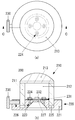
- the pressure vessel 100 provided with the observation window member of the first embodiment is shown, (a) is a top view, and (b) is a schematic cross-sectional view taken along a broken line BB in FIG. 1 (a).
- 1B is an enlarged view of a portion of FIG. 1A showing a joint portion between a flange 111 of an observation window member 110 and a window member 113 in the pressure vessel 100.
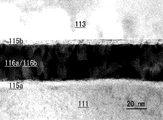
- FIG. 3 is a TEM image showing a joint portion between a flange 111 and a window member 113.
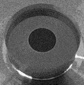
- the external appearance photograph after the pressurization of Example 1 is shown.
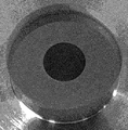
- the external appearance photograph after the pressurization of Example 2 is shown.
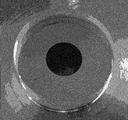
- Example 1 It is an external appearance photograph of Example 1 before and behind a heating hydraulic pressure test, and has shown the state immediately after performing low temperature joining. It is an external appearance photograph of Example 1 before and behind a heating water pressure test, and has shown the state after a heating water pressure test was complete
- FIG. 11 is a process diagram showing a method for manufacturing an observation window member 210 in the observation apparatus 200. It is a cross-sectional schematic diagram which shows the structure of the conventional window member with a sealing mechanism.
- FIG. 1 is a view showing a pressure vessel 100 including an observation window member according to a first embodiment of the present invention
- FIG. 1 (a) is a top view
- FIG. 1 (b) is a view of FIG. It is a schematic cross section in a BB broken line part.
- the observation window member 110 is combined with the vessel 120 and fixed by a plurality of fixing members 130.
- the observation window member 110 is a member that is attached to the container 120 and holds and seals the pressure inside the container 120, and also functions as a view port for visually observing and observing the inside of the container 120 from above.
- the observation window member 110 is provided with a hole 112, a window member 113, and a fixing hole 114 in a flange 111.
- the flange 111 is a substantially disk-shaped metal member having an inner surface facing the container 120 and an outer surface to which the fixing member 130 is attached. Further, a hole 112 and a fixing hole 114 are formed in the flange 111, and a window member 113 is joined to the inner surface side.
- the flange 111 and the window member 113 are two joined bodies in the present invention. Details of the joining of the flange 111 and the window member 113 will be described later.
- the flange 111 is a first object to be joined in the present invention, and is formed of any one of stainless steel, iron, aluminum, an alloy containing iron or aluminum, an alloy of iron and nickel, and an alloy of iron, nickel, and cobalt.
- An alloy containing iron refers to any alloy containing iron, such as steel, and an alloy containing aluminum is mainly composed of aluminum and includes copper (Cu), manganese (Mn), silicon (Si), An alloy containing magnesium (Mg), zinc (Zn), nickel (Ni) or the like is meant.
- Invar registered trademark
- an alloy called Super Invar registered trademark
- the material constituting the flange 111 can be selected from the above-mentioned materials according to the intended use. However, when the function of making the position of the window member less susceptible to the temperature change is given, an invar having a small thermal expansion coefficient (registered) Trademark) or Super Invar (registered trademark). In addition, stainless steel having excellent corrosion resistance is preferable in a highly corrosive environment.
- the hole 112 is a hole provided through the substantial center of the flange 111 from the outer surface side to the inner surface side. Through the hole 112 and the window member 113, the observer can visually recognize the inside of the container 120 from the outside of the pressure container 100. In addition, an observation device such as a camera can be inserted into the hole 112 as necessary, and also functions as a hole for insertion of an observation device.
- the window member 113 is a second member to be joined in the present invention, and is a transparent member joined so as to close the hole 112 at a substantially central position on the inner surface side of the flange 111.
- transparent means that the transmittance with respect to the wavelength of light to be observed is high.
- a material constituting the window member 113 a material that can withstand high pressure, high temperature, corrosion resistance, and the like, which are the use conditions of the pressure vessel 100, is used. Specifically, sapphire or diamond can be used to produce either a single crystal material or a polycrystalline material, but a single crystal material is preferable because of its higher crystal quality.
- sapphire or diamond can be used to produce either a single crystal material or a polycrystalline material, but a single crystal material is preferable because of its higher crystal quality.
- the fixing holes 114 are provided through the flange 111 from the outer surface side to the inner surface side.
- a plurality of fixing holes 114 are provided at rotationally symmetric positions with respect to the center of the flange 111, and the fixing member 130 is inserted.
- the container 120 has a container space 122 and a connection part 123 formed in a container main body 121, and a pipe 124 connected thereto. Further, a sealing groove 125 is formed on the upper surface of the container main body 121, a sealing member 126 is disposed, and a plurality of screw hole portions 127 are formed.
- the container main body 121 is a cylindrical metal container having a top surface, a bottom surface, and a side wall, and is a main body portion of the pressure container 100.
- a container space 122 is opened at a substantially central portion, a sealing groove 125 is formed around the container space 122, and a screw hole portion 127 is formed at a position corresponding to the fixing hole 114 of the flange 111.
- a connecting portion 123 is formed so as to penetrate from the bottom of the container space 122, and a pipe 124 is connected to the connecting portion 123.
- the material constituting the container main body 121 can be appropriately selected depending on the application, but for example, stainless steel can be used.
- An observation window member 110 is fixed to the upper surface side of the container main body 121 by a fixing member 130.
- the container space 122 is a space provided at a substantially central position of the container main body 121 corresponding to the window member 113, and is a space into which the liquid or gas to be observed flows from the outside via the connection portion 123 and the pipe 124. is there.
- the container space 122 is provided with an area larger than the outer shape of the window member 113, and the window member 113 protruding from the flange 111 is accommodated without contacting the container body 121.
- connection portion 123 is a hole that penetrates from the bottom of the container space 122 to the bottom surface of the container main body 121, and allows the liquid or gas to be observed to flow in and out between the pipe 124 and the container space 122. It is.
- the pipe 124 is a path through which the liquid or gas to be observed flows into and out of the pressure vessel 100 from the outside, and is connected to the connection portion 123 on the bottom surface side of the container main body 121.
- the connection 123 and the pipe 124 are connected using a technique such as ordinary welding that can withstand high pressure.
- a technique such as ordinary welding that can withstand high pressure.
- only one connection part 123 and one pipe 124 are shown, but a plurality of connection parts 123 and pipes 124 may be provided if necessary for the inflow and outflow of the observation target.
- the sealing groove 125 is a groove provided on the upper surface of the container main body 121 so as to surround the periphery of the opening region of the container space 122, and the sealing member 126 is disposed therein.
- the sealing member 126 is a member that is accommodated in the sealing groove 125 and is pressed against the bottom of the sealing groove 125 and the flange 111 to maintain the pressure inside the container space 122.
- an O-ring is used.
- the screw hole 127 is a hole formed at a position corresponding to the fixing hole 114 of the flange 111, and a screw groove corresponding to the fixing member 130 is formed on the inner wall portion.
- the fixing member 130 is a member that is inserted into the fixing hole 114 and the screw hole portion 127 to fix the flange 111 to the container 120.
- the flange 111 and the window member 113 are joined, a seal member 126 is disposed around the container space 122, and the observation window member 110 is fixed to the container 120 by the fixing member 130. Pressure is maintained.
- the container space 122 is formed to have a size that allows the window member 113 to be accommodated without contact, the window member 113 contacts the container 120 when the observation window member 110 is attached to the container 120. There is no damage.
- the window member 113 and the flange 111 are joined by surface contact, and no load is applied to the window member 113 when the observation window member 110 is attached to the container 120, the window member is replaced when the observation window member 110 is replaced. 113 can be prevented from being damaged, and the window member 113 can be easily replaced on the user side such as an apparatus or a container.
- FIG. 2 is an enlarged view of a joint portion A between the flange 111 of the observation window member 110 and the window member 113 in the pressure vessel 100. See FIG. 1 for part A.
- a metal layer 115 and a bonding layer 116 are formed around the hole 112 on the surface where the flange 111 and the window member 113 face each other. More specifically, the first metal layer 115a and the first bonding layer 116a are formed on the surface of the flange 111 that is the first object to be bonded, and the surface of the window member 113 that is the second object to be bonded. A second metal layer 115b and a second bonding layer 116b are formed (hereinafter simply referred to as “bonding layers 116a and 116b” and “metal layers 115a and 115b” as necessary). The bonding layers 116a and 116b are bonded to each other by low temperature bonding (normal temperature bonding).
- bonding refers to low-temperature bonding
- low-temperature bonding room temperature bonding
- FIG. 3 is a TEM (Transmission / Electron / Microscope) image showing a joint portion between the flange 111 and the window member 113.
- the boundary surfaces of the bonding layers 116a and 116b become unclear due to the occurrence of atomic diffusion. Therefore, in FIG. 2, in order to schematically illustrate the bonding state of the bonding layers 116a and 116b, a boundary surface between the bonding layers 116a and 116b is indicated by a broken line.
- the metal layers 115a and 115b are film layers composed of metal elements. Specifically, titanium (Ti), chromium (Cr), nickel (Ni), vanadium (V), zirconium (Zr), niobium (Nb ), Tantalum (Ta), scandium (Sc), molybdenum (Mo), tungsten (W), hafnium (Hf), or an alloy thereof, or a laminated film containing at least one of these materials and alloys Either is formed. Among these materials, it is most preferable to use titanium as the metal layers 115a and 115b because the bonding strength between the material of the flange 111 or the window member 113 and the material of the bonding layers 116a and 116b can be improved.
- the bonding layers 116a and 116b are made of gold, an alloy containing gold, platinum, silver, or copper.
- the alloy containing gold include K18 (18 gold), K22 (22 gold), and K24 (24 gold).
- the flange 111 which is the first bonded body is formed of any one of stainless steel, iron, aluminum, an alloy containing iron or aluminum, an alloy of iron and nickel, an alloy of iron, nickel and cobalt, and a metal.
- the layer 115a is formed of any one of titanium, chromium, nickel, vanadium, zirconium, niobium, tantalum, scandium, molybdenum, tungsten, hafnium, an alloy thereof, or a laminated film containing at least one of them, and low-temperature bonding is performed. ing.
- the surfaces of the flange 111 and the window member 113 on which the metal layers 115a and 115b are formed are formed flat with a predetermined accuracy.
- the surface roughness of each surface is set to 1.0 nm or less in terms of arithmetic average roughness Ra in order to obtain sufficient bonding strength.
- Ra exceeds 1.0 nm, it is difficult to obtain a bond having uniform bonding strength over the entire surface, although bonding can be achieved only with a part of the metal layers 115a and 115b and the bonding layers 116a and 116b.
- Ra of each surface forming the metal layers 115a and 115b ensures uniform bonding strength over the entire surfaces of the metal layers 115a and 115b and the bonding layers 116a and 116b, and changes over time. In addition, it is preferable for preventing a decrease in bonding strength with respect to environmental changes and preventing deterioration of the bonded portion.
- Ra can be measured by an atomic force microscope (AFM: Atomic Force Microscope).
- the surface on the side of the window member 113 on which the metal layer 115b is formed does not depend on a specific crystal orientation. Any plane orientation can be selected.
- a method of low-temperature bonding (normal temperature bonding) between the flange 111 and the window member 113 will be described in detail.
- a flange 111 that is a first object to be joined and a window member 113 that is a second object to be joined are prepared.
- the surface on which the metal layer is formed is smoothed to an arithmetic average roughness Ra of 1.0 nm or less.
- CMP Chemical / Mechanical / Polishing
- the processed flange 111 and window member 113 are placed in a container having a vacuum atmosphere with an ultimate vacuum of 10 ⁇ 4 Pa or less, an inert gas is introduced into the vacuum atmosphere, and the metal layers 115a and 115b.
- bonding layers 116a and 116b are formed.
- the metal layers 115a and 115b and the bonding layers 116a and 116b can be formed by physical vapor deposition (PVD) such as sputtering or ion plating, chemical vapor deposition (CVD), various other vapor deposition, or laser ablation.
- PVD physical vapor deposition
- CVD chemical vapor deposition
- a film method PLD: Pulsed Laser Deposition
- the metal layers 115a and 115b and the bonding layers 116a and 116b are formed continuously in the same vacuum degree in the same container.
- the reason is that the flange 111 and the window member 113 are not exposed outside the container after the formation of the metal layers 115a and 115b, so that formation of an oxide film on each surface of the metal layers 115a and 115b is prevented and the bonding strength is reduced. This is because it can be prevented and a processing step for removing the oxide film can be omitted.
- the surfaces of the flange 111 and the window member 113 on which the metal layers 115a and 115b are formed are cleaned by washing with water, cleaning with an organic solvent, irradiation with ultrasonic waves, plasma, or an inert gas beam. Thus, it is preferable to remove the dirt and the oxide film in advance.
- the bonding can be further strengthened.
- the atmosphere on which the flange 111 and the window member 113 are placed is set to an air atmosphere or a vacuum atmosphere.
- the bonding layers 116a and 116b are brought into surface contact with each other, and a predetermined pressure (for example, about 25 MPa) is applied to the flange 111 and the window member 113 in a temperature range of 200 ° C. or lower.
- the flange 111 and the window member in a low-temperature air atmosphere or a vacuum atmosphere within a temperature range of 200 ° C. or less via the bonding layers 116a and 116b. 113) and the window member 110 for observation comprised by the to-be-joined body of the flange 111 and the window member 113 at least is manufactured.
- the atmosphere during the low-temperature bonding is most preferably a vacuum atmosphere because the surfaces of the bonding layers 116a and 116b are not contaminated.
- it is an inert gas such as argon (Ar) or nitrogen (N), there is no problem as an atmosphere during the bonding process.
- Example 1 for low pressure and Example 2 for high pressure were prepared as the observation window member 110 in this example.
- the flange 111 was made of stainless steel (SUS316L), the outer diameter was 70 mm, and the diameter of the hole 112 was 6 mm.
- the window member 113 was formed of a sapphire single crystal material in both Example 1 and Example 2, the outer diameter was 16 mm, and the thickness was 5 mm.
- 5 nm of titanium was formed as the metal layers 115a and 115b, and 20 nm of gold was formed as the bonding layers 116a and 116b.
- the thickness of the flange 111 was 20 mm
- Example 2 for high pressure the thickness was 25 mm.
- the surface on which the metal layer 115b of the window member 113 is formed is a sapphire c-plane. Further, Ra on the surface of the flange 111 and the window member 113 on which the metal layers 115a and 115b are formed was set to 1.0 nm or less.
- each was placed in a vacuum chamber, Ar gas was introduced in a vacuum atmosphere with an ultimate vacuum of 10 ⁇ 4 Pa, and sputtering was used. Thereafter, the atmosphere in the chamber is changed to an air atmosphere, the bonding layers 116a and 116b are brought into surface contact with each other, and are bonded at a low temperature by applying a pressure of about 25 MPa at 20 ° C. Obtained.
- FIGS. 4 and 5 show the bonding state after pressurization in the low temperature bonding process.
- FIG. 4 shows an appearance photograph after pressurization of Example 1.
- FIG. 5 shows an appearance photograph after pressurization of Example 2.
- the flange 111 and the window member 113 Prior to pressurization, the flange 111 and the window member 113 were joined in more than half of the region, but the joining was insufficient.
- After pressurization, in both Example 1 and Example 2 no unbonded portion was observed over the entire region, and good bonding was achieved on the entire surface of the bonding layers 116a and 116b.
- Example 1 for low pressure, the water pressure in the container space 122 was increased to 15 MPa, and in Example 2 for high pressure, it was increased to 45 MPa, held for 5 minutes, removed, and the appearance was inspected.
- Example 1 and Example 2 In both cases, no peeling was observed over the entire surface of the bonding layers 116a and 116b.
- Example 1 for the low pressure, the pressure in the container space 122 was increased to 15 MPa, and in Example 2 for the high pressure, the pressure was increased to 30 MPa and held for 5 minutes, but no bubbles were generated and no leakage occurred.
- Example 2 for the high pressure, the pressure was increased to 30 MPa and held for 5 minutes, but no bubbles were generated and no leakage occurred.
- Example 1 for low pressure, a heating water pressure test was performed by heating to 200 ° C. in an electric furnace while applying a water pressure of 20 MPa, but no leakage occurred at the joint between the flange 111 and the window member 113. It was. 6 and 7 are external photographs of Example 1 before and after the heating water pressure test. FIG. 6 shows a state immediately after the low-temperature bonding, and FIG. 7 shows a state after the heating water pressure test is completed. . As shown in FIG. 7, even after the heating water pressure test was completed, no peeling was observed over the entire surface of the bonding layers 116a and 116b.
- the first and second metal layers are formed on the flange and the window member, and are joined in contact with the first and second metal layers. Since the layer is formed and the flange and the window member are joined, the number of parts can be reduced, and it is easy to change the specifications for using the window member in various devices, making it possible to meet market demands. Become. In addition, since the flange and the window member are joined via the joining layer, it is not necessary to tighten them in combination with other components, and a force is applied to the window member by surface contact, so that damage can be prevented. Therefore, the operator's skill is not required to replace the observation window member, and the window member can be replaced on the user side such as an apparatus or a container.
- FIG. 8 is a view showing an observation apparatus including an observation window member according to the second embodiment of the present invention
- FIG. 8 (a) is a top view
- FIG. 8 (b) is a diagram C in FIG. 8 (a).
- -C is a schematic cross-sectional view taken along a broken line.
- the observation window member 210 is combined with the sample table 220 and fixed by the fixing member 230.
- the observation window member 210 is a member that is attached to the sample stage 220 and functions as a viewport for visually observing and observing the upper part of the sample stage 220 from above.
- a window member 213 is joined to a flange 211, and a hollow portion 212 is formed inside the flange 211.
- the flange 211 is a substantially cylindrical metal member, the inside of the cylinder is a hollow portion 212, and a window member 213 is bonded at one end to a low temperature to function as a spacer.
- the joining of the flange 211 and the window member 213 is a low-temperature joining similar to that of the first embodiment, and a description thereof is omitted.
- any of stainless steel, iron, aluminum, an alloy containing iron or aluminum, an alloy of iron and nickel, or an alloy of iron, nickel and cobalt is used as in the flange 111.
- Invar registered trademark
- Super Invar registered trademark
- sapphire sapphire or diamond is used as in the window member 113.
- the opposite side (the other side) of the window member 213 to the surface joined to the flange 211 is formed into a convex curved surface, and the window member 213 has a function as a lens.
- the curved shape may be spherical or aspherical as long as the optical design as a lens is satisfied.
- the sample table 220 is a table on which the sample 232 is placed in the cavity 212 on the base 221, and the sample 232 is sandwiched between the holding plate 231 and the base 221 and fixed.
- the holding plate 231 is fixed to the sample table 220 by a fixing member 224.
- the fixing member 224 is fixed to a fixing hole 223 formed in the base 221.
- a groove 225 is formed so as to surround the region of the base 221 on which the sample 232 is placed, and the end of the flange 211 on the side where the window member 213 is not joined is inserted into the groove 225.
- a fixing hole 226 having a screw groove formed on the inner surface is formed so as to reach the groove 225.
- the fixing member 230 is screwed into the fixing hole 226, and the tip is brought into contact with the side surface of the flange 211 at the side portion of the groove 225, and is fixed in a state where the height of the flange 211 is adjusted.
- a light source 227 such as a light emitting diode may be disposed as necessary immediately below the area on the base 221 where the sample 232 is placed, and the sample 232 can be irradiated from the back side.
- FIG. 9 is a process diagram showing a method for manufacturing the observation window member 210 in the observation apparatus 200.
- the material such as sapphire constituting the window member 213 is polished flat.
- the flange 211 is processed into a cylindrical shape and joined to one surface of the window member 213.
- a metal layer and a bonding layer are respectively formed in the bonding region between the window member 213 and the flange 211 (not shown), and the temperature is 200 ° C. or less in an air atmosphere or a vacuum atmosphere.
- the bonding layers are brought into contact with each other in the temperature range and pressurized, and two objects to be bonded are bonded by low-temperature bonding.
- the outer diameter of the window member 213 is processed so as to be substantially flush with the side surface of the flange 211.
- the upper surface side of the window member 213 is polished and processed into a convex lens shape.
- the window member 213 does not come into contact with the sample table 220 and is not damaged. Further, the window member 213 and the flange 211 are joined by surface contact, and no load is applied to the window member 213 when attaching the observation window member 210 to the sample table 220. The member 213 can be prevented from being damaged, and the window member 213 can be easily replaced on the user side such as an apparatus or a container.
- observation window member 110 shown in the first embodiment and the observation window member 210 shown in the second embodiment can be attached to various devices (pressure vessel, observation device) by a commonly used flange fixing method. .
- observation window member 110 of the present invention good observation can be performed even if the environment in the pipes is an environment such as high temperature, high pressure, and corrosiveness.
- the window member 113 when sapphire or diamond is used as the window member 113, the wavelength in the ultraviolet light region can be transmitted satisfactorily. Therefore, an ultraviolet region sensor is inserted into the hole 112 of the observation window member 110 to perform observation in the container space 122. be able to.
- a light source and a light receiving element can be inserted into the hole 112 of the observation window member 110 to measure the optical characteristics of the liquid in the container space 122.
- the number of parts can be reduced, the specification can be easily changed, and market demands can be easily met.
- the window member when attaching the observation window member, it does not come into contact with other parts and is not damaged.
- the window member and the flange are joined by surface contact, and the load at the time of attaching the observation window member is not applied to the window member, the window member can be prevented from being damaged at the time of replacing the observation window member.
- the window member can be easily replaced on the user side such as an apparatus or a container.
Landscapes
- Physics & Mathematics (AREA)
- Health & Medical Sciences (AREA)
- Life Sciences & Earth Sciences (AREA)
- Chemical & Material Sciences (AREA)
- Analytical Chemistry (AREA)
- Biochemistry (AREA)
- General Health & Medical Sciences (AREA)
- General Physics & Mathematics (AREA)
- Immunology (AREA)
- Pathology (AREA)
- Optical Measuring Cells (AREA)
- Pressure Welding/Diffusion-Bonding (AREA)
Abstract
【課題】部品点数が少なく、窓部材の交換が容易かつ交換時の窓部材の破損を防止できる観察用窓部材、観察用窓部材を備えた観察装置、圧力容器、配管、濁度計及び観察用窓部材の製造方法を提供する。 【解決手段】観察用窓部材のフランジと窓部材の二つの被接合体に金属層と接合層を形成し、接合層同士を低温接合させる。フランジは、ステンレス鋼、鉄、アルミニウム、鉄又はアルミニウムを含む合金、鉄及びニッケルの合金、鉄とニッケルとコバルトの合金の何れかで形成され、窓部材は、サファイア又はダイヤモンドで形成され、金属層はチタン、クロム、ニッケル、バナジウム、ジルコニウム、ニオブ、タンタル、スカンジウム、モリブデン、タングステン、ハフニウム、又はこれら合金、又は少なくともこれらの何れかを含む積層膜の何れかで形成され、接合層は金、金を含む合金、白金、銀、銅の何れかで形成されている。
Description
本発明は、観察用窓部材、観察用窓部材を備えた観察装置、圧力容器、配管、濁度計、及び観察用窓部材の製造方法に関する。
従来から、高温や高圧などの、通常とは異なる環境下におかれている試料を観察するために、これらの環境に耐えながらも装置内部を観察可能な窓部材が用いられている。例えば特許文献1には、超臨界水、超臨界二酸化炭素等の実験セルの内部を観察するために、高温と高圧、腐食性の高い環境にも耐えうるシール機構付き窓部材が提案されている。
図10は、特許文献1のシール機構付き窓部材の構造を示す模式断面図である。図10に示すように、特許文献1では内部が高温、高圧になる容器の箱体1の開口領域にシール機構付き窓部材としてシールパッキング3、窓部材4、ワッシャー5、押圧金具6を締め付けて取り付けている。押圧金具6の下部には螺子溝が形成されており、開口領域内にシールパッキング3、窓部材4、ワッシャー5をこの順に配置した後に、押圧金具6を箱体1に螺着することで窓部材4をシール状態で取り付けている。
このような従来技術では、窓部材4のシール機構としてシールパッキング3、ワッシャー5、押圧金具6が必要であり、部品点数が多くなるため観察用窓部材の製造コストが増加してしまう。また部品点数が多いことで、窓部材のサイズを変更するなどの仕様変更をする場合には、各部材についてもサイズ変更をする必要があり、観察用窓部材を様々な装置や容器等に用いるために仕様変更することも容易ではなく、市場の要求に応えるのも困難であった。
また、開口領域に複数の部品を配置して押圧金具6で螺着によりシール状態としているため、押圧金具6が螺旋状にねじ込まれながら各部品に力を加えることとなり、窓部材4やシールパッキング3等の部品に均等に力が加わらないという問題もある。押圧金具6の螺旋状のねじ込みでは、窓部材4に対して螺旋状に点接触で力が加わるため、サファイアなどの材料で構成された窓部材4が力の一点集中により破損しやすく、観察用窓部材を装置に取り付けるためには作業者の熟練度が必要となり、装置や容器等の利用者側で窓部材を交換することは困難であった。
本発明は、上記課題に鑑みてなされたものであり、部品点数が少なく、窓部材の交換が容易かつ交換時の窓部材の破損を防止できる観察用窓部材、観察用窓部材を備えた観察装置、圧力容器、配管、濁度計、及び観察用窓部材の製造方法を提供することを目的とする。
上記課題を解決するために、本発明の観察用窓部材は、フランジと窓部材の二つの被接合体を備え、前記フランジの一方の面に第1の金属層が形成され、前記窓部材の前記フランジと対向する一方の面に第2の金属層が形成され、前記第1の金属層と前記第2の金属層とに接して接合層が形成され、前記フランジと前記窓部材とが前記接合層を介して接合され、前記フランジが、ステンレス鋼、鉄、アルミニウム、鉄又はアルミニウムを含む合金、鉄及びニッケルの合金、鉄とニッケルとコバルトの合金の何れかで形成され、前記窓部材が、サファイア又はダイヤモンドで形成され、前記第1の金属層及び前記第2の金属層が、チタン、クロム、ニッケル、バナジウム、ジルコニウム、ニオブ、タンタル、スカンジウム、モリブデン、タングステン、ハフニウム、又はこれら合金、又は少なくともこれらの何れかを含む積層膜の何れかで形成され、前記接合層が、金、金を含む合金、白金、銀、銅の何れかで形成されていることを特徴とする。
このような本発明の観察用窓部材では、フランジと窓部材に第1及び第2の金属層を形成し、第1及び第2の金属層に接して接合層を形成してフランジと窓部材を接合しているため部品点数を減少させることができ、窓部材を様々な装置に用いるための仕様変更も容易になり、市場の要求に応えることが可能となる。また、フランジと窓部材とが接合層を介して接合されていることにより、他の部品と組み合わせて締め付ける必要がなく、窓部材に対して面接触で力が加わることから破損を防止できる。したがって、観察用窓部材の交換に作業者の熟練が不要となり、装置や容器等の利用者側で窓部材を交換することが可能となる。
また、本発明の一実施態様では、前記第1の金属層及び/又は前記第2の金属層がチタンで形成される。
また、本発明の一実施態様では、前記接合層が金で形成される。
また、本発明の一実施態様では、前記窓部材の他方の面が、凸面形状に成形されている。
また、本発明の一実施態様では、観察装置、圧力容器、配管、又は濁度計に上記観察用窓部材を備える。
また上記課題を解決するために、本発明の観察用窓部材の製造方法は、ステンレス鋼、鉄、アルミニウム、鉄又はアルミニウムを含む合金、鉄及びニッケルの合金、鉄とニッケルとコバルトの合金の何れかで形成されるフランジと、サファイア又はダイヤモンドで形成される窓部材を用意する工程と、到達真空度が10-4Pa以下の真空雰囲気中に前記フランジ及び前記窓部材を載置した後に不活性ガスを導入する工程と、チタン、クロム、ニッケル、バナジウム、ジルコニウム、ニオブ、タンタル、スカンジウム、モリブデン、タングステン、ハフニウム、又はこれら合金、又は少なくともこれらの何れかを含む積層膜の何れかで、第1の金属層及び第2の金属層をそれぞれ前記フランジの一方の面上及び前記窓部材の一方の面上に形成する工程と、金、金を含む合金、白金、銀、銅の何れかで、第1の接合層及び第2の接合層をそれぞれ前記第1の金属層上及び前記第2の金属層上に形成する工程と、前記第1の接合層と前記第2の接合層とを接触させて、大気雰囲気中又は真空雰囲気中で200℃以下の温度範囲で接合して、前記フランジと前記窓部材とを前記第1の接合層及び前記第2の接合層を介して接合する工程、とを備えることを特徴とする。
このような本発明の観察用窓部材の製造方法では、フランジと窓部材にそれぞれ第1、第2の金属層と第1、第2の接合層を形成し、200℃以下の低温(常温)接合でフランジと窓部材を接合しているため部品点数を減少させることができ、窓部材を様々な装置に用いるための仕様変更も容易になり、市場の要求に応えることが可能となる。また、フランジと窓部材とを第1、第2の接合層で低温(常温)接合することにより、他の部品と組み合わせて締め付ける必要がなく、窓部材に対して面接触で力が加わることから破損を防止できる。したがって、観察用窓部材の交換に作業者の熟練が不要となり、装置や容器等の利用者側で窓部材を交換することが可能となる。
また、本発明の一実施態様では、前記第1の金属層及び/又は前記第2の金属層をチタンで形成する。
また、本発明の一実施態様では、前記第1の接合層及び/又は前記第2の接合層を金で形成する。
また、本発明の一実施態様では、前記第1の金属層及び前記第2の金属層を形成する工程の前に、前記フランジの一方の面及び前記窓部材の一方の面をクリーニングする工程を備える。
また、本発明の一実施態様では、前記窓部材の他方の面を、凸面形状に成形する。
本発明では、部品点数が少なく、窓部材の交換が容易かつ交換時の窓部材の破損を防止できる観察用窓部材、観察用窓部材を備えた観察装置、圧力容器、配管、濁度計、及び観察用窓部材の製造方法を提供することができる。
以下、本発明の第1実施形態について図面を参照して詳細に説明する。図1は本発明の第1実施形態に係る観察用窓部材を備える圧力容器100を示す図であり、図1(a)は上面図であり、図1(b)は図1(a)のB-B破線部での模式断面図である。図1に示すように、圧力容器100では、観察用窓部材110を容器120に組み合わせ、複数の固定部材130で固定している。
観察用窓部材110は、容器120に取り付けられて容器120内部の圧力を保持して密閉するとともに、上部から容器120の内部を視認して観察するためのビューポートとして機能する部材である。観察用窓部材110は、フランジ111に孔部112、窓部材113、固定用孔114が設けられている。
フランジ111は、容器120と対向する内面と固定部材130が取り付けられる外面とを有する略円盤状の金属製部材である。またフランジ111には孔部112と固定用孔114が形成されており、内面側には窓部材113が接合されている。フランジ111と窓部材113は本発明における二つの被接合体である。フランジ111と窓部材113との接合についての詳細は後述する。
フランジ111は本発明における第1の被接合体であり、ステンレス鋼、鉄、アルミニウム、鉄又はアルミニウムを含む合金、鉄及びニッケルの合金、鉄とニッケルとコバルトの合金の何れかで形成される。鉄を含む合金とは、例えば鋼のように鉄を含有するあらゆる合金を指し、またアルミニウムを含む合金とは、アルミニウムを主成分とし、銅(Cu)、マンガン(Mn)、ケイ素(Si)、マグネシウム(Mg)、亜鉛(Zn)、ニッケル(Ni)等を含む合金を指すものとする。鉄及びニッケルの合金としては、インバー(登録商標)と呼ばれる、鉄に約36at%のニッケルを加えた合金が知られている。また、鉄とニッケルとコバルトの合金としては、スーパーインバー(登録商標)と呼ばれる、鉄に約31.5at%のニッケルと、約5at%のコバルトを加えた合金が知られている。
フランジ111を構成する材料としては、上述したものの中から用途に応じて選択できるが、窓部材の位置が温度変化の影響を受けにくくする機能を持たせる場合は、熱膨張係数が小さいインバー(登録商標)またはスーパーインバー(登録商標)が好ましい。また、腐食性の高い環境下では耐食性に優れたステンレス鋼が好ましい。
孔部112は、フランジ111の略中心を外面側から内面側まで貫通して設けられた孔である。孔部112と窓部材113を介して、観察者は圧力容器100の外部から容器120の内部を視認できる。また、孔部112には必要に応じてカメラなどの観測機器を挿入することができ、観測機器挿入用の孔としても機能する。
窓部材113は、本発明における第2の被接合体であり、フランジ111の内面側で略中央位置に孔部112を塞ぐように接合された透明の部材である。ここで、透明とは観測対象となる光の波長に対する透過率が高いことを意味している。窓部材113を構成する材料としては、圧力容器100の使用条件である高圧や高温、耐腐食性などに耐えうる材料を用いる。具体的にはサファイア又はダイヤモンドを用い、単結晶材料又は多結晶材料のどちらでも作製可能であるが、単結晶材料の方が結晶品質が高いため好ましい。また、フランジ111への接合時や接合後の機械的強度を確保するためには、欠けや割れ、クラックが無いものを用いることが好ましい。
固定用孔114は、フランジ111の外面側から内面側まで貫通して設けられた孔であり、フランジ111の中心に対して回転対称の位置に複数設けられて、固定部材130が挿入される。
容器120は、容器本体121に容器空間122と接続部123が形成され、配管124が接続されている。また、容器本体121の上面にはシール用溝125が形成されてシール部材126が配置されており、螺子孔部127が複数形成されている。
容器本体121は、上面と底面と側壁を備える円筒形状の金属製容器であり、圧力容器100の本体部分である。上面側には、略中心部分に容器空間122が開口して設けられており、その周囲にシール用溝125が形成され、フランジ111の固定用孔114と対応する位置に螺子孔部127が形成されている。底面側には、容器空間122の底部から接続部123が貫通して形成され、接続部123に配管124が接続されている。容器本体121を構成する材料としては、用途に応じて適宜選択可能であるが、例えばステンレスなどを用いることができる。容器本体121の上面側には、観察用窓部材110が固定部材130によって固定されている。
容器空間122は、窓部材113と対応する容器本体121の略中央位置に設けられた空間であり、接続部123と配管124を介して外部から観測対象である液体または気体が流入される空間である。また容器空間122は、窓部材113の外形よりも大きい面積として設けられており、フランジ111から突出した窓部材113が容器本体121と接触せずに収容される。
接続部123は、容器空間122の底部から容器本体121の底面にわたって貫通して設けられた孔であり、観測対象である液体または気体を配管124と容器空間122との間での流出入させる経路である。
配管124は、外部から圧力容器100に観測対象である液体または気体を流出入させる経路であり、容器本体121の底面側で接続部123に接続されている。接続部123と配管124との接続は、高圧に耐えうる通常の溶接等の技術を用いる。図中では接続部123と配管124を一つだけ示しているが、観測対象の流出入などに必要であれば複数設けても構わない。
シール用溝125は、容器本体121の上面で、容器空間122の開口領域周辺を囲んで設けられた溝であり、シール部材126が配置される。
シール部材126は、シール用溝125に収容されてシール用溝125の底とフランジ111に圧接され、容器空間122内部の圧力を保持するための部材であり、例えばOリングが用いられる。
螺子孔部127は、フランジ111の固定用孔114と対応する位置に形成された孔であり、内壁部分には固定部材130と対応する螺子溝が形成されている。
固定部材130は、固定用孔114と螺子孔部127に挿入されてフランジ111を容器120に固定するための部材であり、螺子孔部127の螺子溝に対応した螺子山が形成されたボルト等を用いることができる。
図1に示したように、フランジ111と窓部材113とは接合されており、容器空間122の周囲ではシール部材126が配置され、観察用窓部材110が容器120に固定部材130で固定されて圧力が保持されている。これにより、窓部材113と容器120との間に別途シールパッキングなどをシール機構として介在させる必要がなく、部品点数を削減し仕様変更が容易になり、市場の要求に応えるのも容易になる。また、容器空間122は窓部材113が接触せずに収容される大きさに形成されているため、観察用窓部材110を容器120に取り付ける際にも、窓部材113が容器120に接触して破損することがない。さらに、窓部材113とフランジ111とは面接触で接合され、窓部材113には観察用窓部材110を容器120に取り付ける際の荷重は加わらないため、観察用窓部材110の交換作業時に窓部材113が破損することを防止でき、装置や容器等の利用者側で窓部材113を容易に交換することができる。
次に図2,3を用いて、第1実施形態におけるフランジ111と窓部材113との接合について詳細に説明する。図2は、圧力容器100における観察用窓部材110のフランジ111と窓部材113との接合部分Aの拡大図である。A部分は図1を参照。
図2に示すように、フランジ111と窓部材113がお互いに対向する面には、孔部112周囲に金属層115及び接合層116が形成されている。より詳細には第1の被接合体であるフランジ111の面上に第1の金属層115aと第1の接合層116aが形成され、第2の被接合体である窓部材113の面上に第2の金属層115bと第2の接合層116bが形成されている(以下、必要に応じて、単に「接合層116a,116b」、「金属層115a,115b」と表記する)。接合層116a,bは、互いに低温接合(常温接合)により接合されている。ここで「接合」とは低温接合を指し、更に「低温接合(常温接合)」とは、接合時の温度を200℃以下に設定し、接合層116a,116bの表面における原子拡散を利用した接合方法を指すものとする。
図3は、フランジ111と窓部材113との接合部分を示すTEM(Transmission Electron Microscope:透過型電子顕微鏡)像である。図3に示すように、接合層116a,116bの境界面は原子拡散の発生により不鮮明となる。よって図2では接合層116a,116bの接合状態を模式的に図示するため、接合層116a,116b間の境界面を破線で示している。
金属層115a,115bは、金属元素から構成される膜層であり、具体的にはチタン(Ti)、クロム(Cr)、ニッケル(Ni)、バナジウム(V)、ジルコニウム(Zr)、ニオブ(Nb)、タンタル(Ta)、スカンジウム(Sc)、モリブデン(Mo)、タングステン(W)、ハフニウム(Hf)と云った材料、又はこれら合金、又は少なくともこれらの材料や合金の何れかを含む積層膜の何れかで形成される。これら材料の中でも、金属層115a,115bとしてチタンを用いることが、フランジ111又は窓部材113の材料と、接合層116a,116bの材料との接合強度を向上させることが可能になるため最も好ましい。
一方、接合層116a,116bは金、金を含む合金、白金、銀、銅の何れかで形成される。金を含む合金としては、K18(18金)やK22(22金)、又はK24(24金)が挙げられる。接合層116a,116bをこれらの材料で形成することで、接合部分に耐腐食性も付与することが可能となり、経年変化及び環境変化に対する接合強度の低下及び接合部分の劣化等を防止することが出来る。接合層116a,116bを構成する材料としては、拡散速度が速く接合が容易になるという点から、金が最も好ましい。
また、第1の被接合体であるフランジ111を、ステンレス鋼、鉄、アルミニウム、鉄又はアルミニウムを含む合金、鉄及びニッケルの合金、鉄とニッケルとコバルトの合金の何れかで形成すると共に、金属層115aをチタン、クロム、ニッケル、バナジウム、ジルコニウム、ニオブ、タンタル、スカンジウム、モリブデン、タングステン、ハフニウム、又はこれら合金、又は少なくともこれらの何れかを含む積層膜の何れかで形成して低温接合を行っている。
金属層115a、115bが形成されるフランジ111と窓部材113の表面は、所定の精度で平坦に形成する。各面の表面粗さは、十分な接合強度を得るために、算術平均粗さRaで1.0nm以下に設定される。Raが1.0nmを超えると、金属層115a,115bと接合層116a,116bの一部分のみでの接合は得られるものの、全面に亘って均一な接合強度を有する接合を得ることは困難となる。
したがって、金属層115a、115bを形成する各面のRaを1.0nm以下に設定することが、金属層115a、115bと接合層116a,116bの全面に亘る均一な接合強度を確保し、経年変化及び環境変化に対する接合強度の低下を防止し、接合部分の劣化等を防止するために好ましい。なおRaの測定は、原子間力顕微鏡(AFM:Atomic Force Microscope)により行うことができる。
なおフランジ111と窓部材113は、金属層115a,115b及び接合層116a,116bを介して接合されるため、窓部材113の金属層115bを形成する側の面は、特定の結晶方位によらず任意の面方位を選択することが可能である。
次に、フランジ111と窓部材113の低温接合(常温接合)の方法を詳細に説明する。まず、第1の被接合体であるフランジ111と、第2の被接合体である窓部材113を用意する。
最初に、フランジ111と窓部材113を構成する素材を所定の形状にするために機械加工を行った後、金属層を形成する面については算術平均粗さRaが1.0nm以下に平滑化するために化学的機械研磨(CMP:Chemical Mechanical Polishing)を行う。
次に、加工されたフランジ111と窓部材113を到達真空度が10-4Pa以下の真空雰囲気である容器内に載置し、真空雰囲気中に不活性ガスを導入し、金属層115a,115bを形成した後に、接合層116a,116bを形成する。金属層115a,115b及び接合層116a,116bの形成方法としては、スパッタリングやイオンプレーティングといった物理蒸着(PVD:Physical Vapor Deposition)、化学蒸着(CVD:Chemical Vapor Deposition)、その他各種蒸着、レーザアブレーション成膜法(PLD:Pulsed Laser Deposition)等を適宜用いれば良い。
金属層115a,115bと接合層116a,116bの形成は、同一容器内で同一真空度中で連続して形成することが好ましい。その理由は、金属層115a,115bの形成後にフランジ111や窓部材113を容器外部に出さないことで、金属層115a,115bの各面への酸化膜の形成が防止され、接合強度の低下が防止されると共に、酸化膜を削除するための処理工程も省略することが可能となるためである。
金属層115a,115bを形成する前に、フランジ111と窓部材113の金属層115a,115bを形成する面は、水洗、有機溶剤による洗浄、超音波、プラズマ、又は不活性ガスビームの照射等によりクリーニングして汚れや酸化被膜等を予め除去しておくことが好ましい。フランジ111と窓部材113の表面をクリーニングしてから金属層115a,115bを形成することで、接合をより強固にすることが可能となる。
金属層115a,115b及び接合層116a,116bの形成後、フランジ111と窓部材113が載置されている雰囲気を大気雰囲気又は真空雰囲気に設定する。次に、接合層116a,116b同士を面接触させ、200℃以下の温度範囲でフランジ111と窓部材113に所定の圧力(例えば、約25MPa)を加える。
このような低温接合(常温接合)工程によって、接合層116a,116bを介して200℃以下の温度範囲内の低温の大気雰囲気中又は真空雰囲気中で二つの被接合体(フランジ111と、窓部材113)を接合し、少なくともフランジ111と窓部材113の二つの被接合体で構成される観察用窓部材110を製造する。なお、低温接合時の雰囲気は、接合層116a,116bの表面が汚染されないという点から、真空雰囲気が最も好ましい。但し、アルゴン(Ar)や窒素(N)などの不活性ガスであれば、接合工程中の雰囲気として問題は無い。
以下に本発明の実施例を説明するが、本発明は以下の実施例にのみ限定されるものではない。
本実施例における観察用窓部材110として、低圧用の実施例1と高圧用の実施例2を作成した。実施例1と実施例2ともに、フランジ111はステンレス鋼(SUS316L)を材料として用い、外径を70mm、孔部112の直径6mmとした。窓部材113は実施例1と実施例2ともに、サファイア単結晶材料で形成し、外径を16mmとし、厚みを5mmとした。また、実施例1と実施例2ともに、金属層115a,115bとしてチタンを5nm形成し、接合層116a,116bとして金を20nm形成した。低圧用の実施例1はフランジ111の厚さを20mmとし、高圧用の実施例2は厚さを25mmとした。
なお、窓部材113の金属層115bを形成する面はサファイアのc面とした。また、フランジ111および窓部材113の金属層115a,115bを形成する表面でのRaは1.0nm以下とした。
金属層115a,115b及び接合層116a,116bの形成には、それぞれを真空チャンバー内に載置し、到達真空度10-4Paの真空雰囲気中でArガスを導入し、スパッタリングを用いた。その後、チャンバー内の雰囲気を大気雰囲気とし、接合層116a,116b同士を面接触させ、20℃で約25MPaの圧力を加えて低温接合し、観察用窓部材110の実施例1および実施例2を得た。
低温接合工程における、加圧後の接合状態を図4,5に示す。図4は実施例1の加圧後の外観写真を示している。図5は実施例2の加圧後の外観写真を示している。加圧前にはフランジ111と窓部材113とは半分以上の領域で接合されているが、接合が不十分であった。加圧後には実施例1と実施例2ともに、全領域にわたって未接合部が観察されず、接合層116a,116bの全面において良好に接合された。
次に、観察用窓部材110を容器120に取り付け、容器空間122内部に常温で水を導入して常温水圧試験を行った。低圧用の実施例1では容器空間122内の水圧を15MPaまで加圧し、高圧用の実施例2では45MPaまで加圧し、5分間保持後に取り外して外観を検査したところ、実施例1と実施例2ともに、接合層116a,116bの全面にわたって剥離は見られなかった。
次に、観察用窓部材110を容器120に取り付け水槽に浸漬し、容器空間122内部に窒素ガスを導入して、気泡の有無を観察してリークを判断する窒素ガスリーク試験を行った。低圧用の実施例1では容器空間122内の気圧を15MPaまで加圧し、高圧用の実施例2では30MPaまで加圧し、5分間保持したが気泡は発生せず、リークは起こらなかった。試験後に取り外して外観を検査したところ、実施例1と実施例2ともに、接合層116a,116bの全面にわたって剥離は見られなかった。
さらに、低圧用の実施例1については水圧20MPaを加えながら、電気炉内で200℃まで加熱し、加熱水圧試験を行ったが、フランジ111と窓部材113との接合部分におけるリークは発生しなかった。図6及び図7は、加熱水圧試験前後の実施例1の外観写真であり、図6は低温接合をした直後の状態を示し、図7は加熱水圧試験が終了した後の状態を示している。図7に示すように、加熱水圧試験終了後においても、接合層116a,116bの全面にわたって剥離は見られなかった。
上述したように、低圧用の実施例1および高圧用の実施例2のいずれにおいても、窒素ガス圧試験、常温水圧試験においてフランジ111と窓部材113との接合領域において剥離は認められず、実施例1の加熱水圧試験の前後においても接合領域の剥離は認められず、良好な接合が維持されていることが確認できた。
このように、本発明の観察用窓部材および観察用窓部材の製造方法では、フランジと窓部材に第1及び第2の金属層を形成し、第1及び第2の金属層に接して接合層を形成してフランジと窓部材を接合しているため部品点数を減少させることができ、窓部材を様々な装置に用いるための仕様変更も容易になり、市場の要求に応えることが可能となる。また、フランジと窓部材とが接合層を介して接合されていることにより、他の部品と組み合わせて締め付ける必要がなく、窓部材に対して面接触で力が加わることから破損を防止できる。したがって、観察用窓部材の交換に作業者の熟練が不要となり、装置や容器等の利用者側で窓部材を交換することが可能となる。
以下、本発明の第2実施形態について図面を参照して詳細に説明する。第1実施形態と重複する内容は説明を省略する。図8は本発明の第2実施形態に係る観察用窓部材を備える観察装置を示す図であり、図8(a)は上面図であり、図8(b)は図8(a)のC-C破線部での模式断面図である。図8に示すように、観察装置200では、観察用窓部材210を試料台220に組み合わせ、固定部材230で固定している。
観察用窓部材210は、試料台220に取り付けられ上部から試料台220の上部を視認して観察するためのビューポートとして機能する部材である。観察用窓部材210は、フランジ211に窓部材213を接合されており、フランジ211の内部には空洞部212が形成されている。
フランジ211は、略円筒形状の金属製部材であり円筒内部が空洞部212とされ、一方の端部には窓部材213が低温接合されてスペーサーとして機能する部材である。フランジ211と窓部材213との接合は、第1実施形態と同様の低温接合であり説明を省略する。
フランジ211を構成する材料としては、フランジ111と同様、ステンレス鋼、鉄、アルミニウム、鉄又はアルミニウムを含む合金、鉄及びニッケルの合金、鉄とニッケルとコバルトの合金の何れかが用いられる。観察装置としての機能上の観点から、レンズ焦点位置が温度変化により変動しないように、フランジ211の材料としては熱膨張係数が小さいインバー(登録商標)またはスーパーインバー(登録商標)が好ましい。一方、窓部材213を構成する材料としては、窓部材113と同様、サファイア又はダイヤモンドが用いられる。
図8に示したように、窓部材213のうちフランジ211と接合された面と反対側(他方の面)は、凸面形状の曲面に成形されており、窓部材213はレンズとしての機能を備えている。曲面形状としてはレンズとしての光学的設計を満たしていれば球面でも非球面でもよい。
試料台220は、ベース221上の空洞部212内に試料232を載置する台であり、試料232は押さえ板231とベース221の間に挟み込まれて固定される。押さえ板231は、固定部材224によって試料台220に固定される。更に固定部材224は、ベース221に形成された固定孔223に、それぞれ固定される。また、試料232を載置するベース221の領域を囲んで溝225が形成されており、溝225にはフランジ211の窓部材213が接合されていない側の端部が挿入されている。試料台220の側面には、内面に螺子溝が形成された固定用孔226が溝225まで到達して形成されている。固定用孔226には、固定部材230が捻じ込まれて溝225の側部で先端がフランジ211の側面に当接され、フランジ211の高さを調整した状態で固定している。また、ベース221の試料232を載置する領域の直下には、必要に応じて発光ダイオードなどの光源227を配置しておき、試料232を裏面側から照射することができる。
図9は、観察装置200における観察用窓部材210の製造方法を示す工程図である。図9(a)に示すように、窓部材213を構成するサファイア等の材料を平坦に研磨する。次に、図9(b)に示すように、フランジ211を円筒形状に加工して窓部材213の一方の面に接合する。このとき、第1実施形態と同様に窓部材213とフランジ211の接合領域には、それぞれ金属層と接合層を形成しておき(図示省略)、大気雰囲気中又は真空雰囲気中で200℃以下の温度範囲で接合層同士を接触させて加圧し、低温接合によって2つの被接合体を接合させる。
次に図9(c)に示すように、窓部材213の外径を加工してフランジ211の側面と略面一となるように成形する。最後に、図9(d)に示すように、窓部材213の上面側を研磨加工して凸面のレンズ形状に加工する。これにより、窓部材213の上面が凸面形状のレンズとして機能するため、観察装置200においては、押さえ板231とベース221の間に固定された試料232を拡大して観察することが可能となる。
また、本実施形態においても、窓部材213と試料台220との間に別途シールパッキングなどをシール機構として介在させる必要がなく、部品点数を削減し仕様変更が容易になり、市場の要求に応えるのも容易になる。また、観察用窓部材210を試料台220に取り付ける際にも、窓部材213が試料台220に接触して破損することがない。さらに、窓部材213とフランジ211とは面接触で接合され、窓部材213には観察用窓部材210を試料台220に取り付ける際の荷重は加わらないため、観察用窓部材210の交換作業時に窓部材213が破損することを防止でき、装置や容器等の利用者側で窓部材213を容易に交換することができる。
次に、本発明の第3実施形態として、本発明の観察用窓部材を適用できる用途を例示して説明する。第1実施形態に示した観察用窓部材110や、第2実施形態に示した観察用窓部材210は、通常用いられるフランジの固定方法で各種装置(圧力容器、観察装置)に取り付けることができる。
例えば、各種配管を分岐して本発明の観察用窓部材110を取り付けることで、配管内の環境が高温、高圧、腐食性などの環境であっても、良好な観察をすることができる。
また、窓部材113としてサファイアやダイヤモンドを用いると、紫外光領域の波長も良好に透過できるため、観察用窓部材110の孔部112に紫外線領域センサを挿入して容器空間122内の観測を行うことができる。
また、観察用窓部材110の孔部112に光源と受光素子を挿入して容器空間122内の液体の光学的な特性を測定することもでき、下水処理場の濁度計に用いることで、下水の濁り度合いをモニタすることが可能となる。下水以外の濁り対象物モニタ用にも適用可能である。なお本願では、モニタや観測も観察に含むものとする。
これらの本発明を用いた各種用途においても、シールパッキングなどをシール機構として介在させる必要がなく、部品点数を削減し仕様変更が容易になり、市場の要求に応えるのも容易になる。また、観察用窓部材を取り付ける際にも、他の部品に接触して破損することがない。さらに、窓部材とフランジとは面接触で接合され、窓部材には観察用窓部材を取り付ける際の荷重は加わらないため、観察用窓部材の交換作業時に窓部材が破損することを防止でき、装置や容器等の利用者側で窓部材を容易に交換することができる。
100…圧力容器
110…観察用窓部材
111…フランジ
113…窓部材
115a,115b…金属層
116a,116b…接合層
120…容器
122…容器空間
125…シール用溝
126…シール部材
200…観察装置
210…観察用窓部材
211…フランジ
213…窓部材
220…試料台
110…観察用窓部材
111…フランジ
113…窓部材
115a,115b…金属層
116a,116b…接合層
120…容器
122…容器空間
125…シール用溝
126…シール部材
200…観察装置
210…観察用窓部材
211…フランジ
213…窓部材
220…試料台
Claims (10)
- フランジと窓部材の二つの被接合体を備え、
前記フランジの一方の面に第1の金属層が形成され、
前記窓部材の前記フランジと対向する一方の面に第2の金属層が形成され、
前記第1の金属層と前記第2の金属層とに接して接合層が形成され、前記フランジと前記窓部材とが前記接合層を介して接合され、
前記フランジが、ステンレス鋼、鉄、アルミニウム、鉄又はアルミニウムを含む合金、鉄及びニッケルの合金、鉄とニッケルとコバルトの合金の何れかで形成され、
前記窓部材が、サファイア又はダイヤモンドで形成され、
前記第1の金属層及び前記第2の金属層が、チタン、クロム、ニッケル、バナジウム、ジルコニウム、ニオブ、タンタル、スカンジウム、モリブデン、タングステン、ハフニウム、又はこれら合金、又は少なくともこれらの何れかを含む積層膜の何れかで形成され、
前記接合層が、金、金を含む合金、白金、銀、銅の何れかで形成されていることを特徴とする観察用窓部材。 - 請求項1に記載の観察用窓部材であって、
前記第1の金属層及び/又は前記第2の金属層がチタンで形成されることを特徴とする観察用窓部材。 - 請求項1又は2に記載の観察用窓部材であって、
前記接合層が金で形成されることを特徴とする観察用窓部材。 - 請求項1~3の何れか1つに記載の観察用窓部材であって、
前記窓部材の他方の面が、凸面形状に成形されていることを特徴とする観察用窓部材。 - 請求項1~4の何れかに1つに記載の観察用窓部材を備えることを特徴とする、観察装置、圧力容器、配管、又は濁度計。
- ステンレス鋼、鉄、アルミニウム、鉄又はアルミニウムを含む合金、鉄及びニッケルの合金、鉄とニッケルとコバルトの合金の何れかで形成されるフランジと、サファイア又はダイヤモンドで形成される窓部材を用意する工程と、
到達真空度が10-4Pa以下の真空雰囲気中に前記フランジ及び前記窓部材を載置した後に不活性ガスを導入する工程と、
チタン、クロム、ニッケル、バナジウム、ジルコニウム、ニオブ、タンタル、スカンジウム、モリブデン、タングステン、ハフニウム、又はこれら合金、又は少なくともこれらの何れかを含む積層膜の何れかで、第1の金属層及び第2の金属層をそれぞれ前記フランジの一方の面上及び前記窓部材の一方の面上に形成する工程と、
金、金を含む合金、白金、銀、銅の何れかで、第1の接合層及び第2の接合層をそれぞれ前記第1の金属層上及び前記第2の金属層上に形成する工程と、
前記第1の接合層と前記第2の接合層とを接触させて、大気雰囲気中又は真空雰囲気中で200℃以下の温度範囲で接合して、前記フランジと前記窓部材とを前記第1の接合層及び前記第2の接合層を介して接合する工程、とを備えることを特徴とする観察用窓部材の製造方法。 - 請求項6に記載の観察用窓部材の製造方法であって、
前記第1の金属層及び/又は前記第2の金属層をチタンで形成することを特徴とする観察用窓部材の製造方法。 - 請求項6又は7に記載の観察用窓部材の製造方法であって、
前記第1の接合層及び/又は前記第2の接合層を金で形成することを特徴とする観察用窓部材の製造方法。 - 請求項6~8の何れか1つに記載の観察用窓部材の製造方法であって、
前記第1の金属層及び前記第2の金属層を形成する工程の前に、前記フランジの一方の面及び前記窓部材の一方の面をクリーニングする工程を備えることを特徴とする観察用窓部材の製造方法。 - 請求項6~9の何れか1つに記載の観察用窓部材の製造方法であって、
前記窓部材の他方の面を、凸面形状に成形することを特徴とする観察用窓部材の製造方法。
Priority Applications (1)
| Application Number | Priority Date | Filing Date | Title |
|---|---|---|---|
| JP2017537570A JPWO2017038140A1 (ja) | 2015-08-28 | 2016-03-31 | 観察用窓部材、観察用窓部材を備えた観察装置、圧力容器、配管、濁度計、及び観察用窓部材の製造方法 |
Applications Claiming Priority (2)
| Application Number | Priority Date | Filing Date | Title |
|---|---|---|---|
| JP2015-168425 | 2015-08-28 | ||
| JP2015168425 | 2015-08-28 |
Publications (1)
| Publication Number | Publication Date |
|---|---|
| WO2017038140A1 true WO2017038140A1 (ja) | 2017-03-09 |
Family
ID=58186944
Family Applications (1)
| Application Number | Title | Priority Date | Filing Date |
|---|---|---|---|
| PCT/JP2016/060596 Ceased WO2017038140A1 (ja) | 2015-08-28 | 2016-03-31 | 観察用窓部材、観察用窓部材を備えた観察装置、圧力容器、配管、濁度計、及び観察用窓部材の製造方法 |
Country Status (3)
| Country | Link |
|---|---|
| JP (1) | JPWO2017038140A1 (ja) |
| TW (1) | TW201708805A (ja) |
| WO (1) | WO2017038140A1 (ja) |
Cited By (2)
| Publication number | Priority date | Publication date | Assignee | Title |
|---|---|---|---|---|
| CN114324175A (zh) * | 2020-09-28 | 2022-04-12 | 株式会社堀场Stec | 光学测定用池和光学分析装置 |
| WO2023281816A1 (ja) * | 2021-07-09 | 2023-01-12 | 株式会社堀場エステック | 光学測定用セル、光学分析装置、窓形成部材、及び光学測定用セルの製造方法 |
Citations (7)
| Publication number | Priority date | Publication date | Assignee | Title |
|---|---|---|---|---|
| JPH02257040A (ja) * | 1988-12-15 | 1990-10-17 | Kobe Steel Ltd | 単純容器型結晶観察装置 |
| US5054919A (en) * | 1989-02-07 | 1991-10-08 | Linear Instruments Corporation | Seal for high pressure and small volume sample cells |
| JPH07209158A (ja) * | 1994-01-13 | 1995-08-11 | Rikagaku Kenkyusho | 高圧装置 |
| JP2000210550A (ja) * | 1999-01-21 | 2000-08-02 | Agency Of Ind Science & Technol | 光化学反応観測用反応セル |
| JP2005329330A (ja) * | 2004-05-20 | 2005-12-02 | Yokogawa Electric Corp | 高温・高圧用容器用窓の構造 |
| JP2008216094A (ja) * | 2007-03-06 | 2008-09-18 | Kurabo Ind Ltd | 透過光測定用フローセル |
| US20080252881A1 (en) * | 2007-04-10 | 2008-10-16 | Schlumberger Technology Corporation | High-pressure cross-polar microscopy cells having adjustable fluid passage and methods of use |
-
2016
- 2016-03-09 TW TW105107154A patent/TW201708805A/zh unknown
- 2016-03-31 WO PCT/JP2016/060596 patent/WO2017038140A1/ja not_active Ceased
- 2016-03-31 JP JP2017537570A patent/JPWO2017038140A1/ja active Pending
Patent Citations (7)
| Publication number | Priority date | Publication date | Assignee | Title |
|---|---|---|---|---|
| JPH02257040A (ja) * | 1988-12-15 | 1990-10-17 | Kobe Steel Ltd | 単純容器型結晶観察装置 |
| US5054919A (en) * | 1989-02-07 | 1991-10-08 | Linear Instruments Corporation | Seal for high pressure and small volume sample cells |
| JPH07209158A (ja) * | 1994-01-13 | 1995-08-11 | Rikagaku Kenkyusho | 高圧装置 |
| JP2000210550A (ja) * | 1999-01-21 | 2000-08-02 | Agency Of Ind Science & Technol | 光化学反応観測用反応セル |
| JP2005329330A (ja) * | 2004-05-20 | 2005-12-02 | Yokogawa Electric Corp | 高温・高圧用容器用窓の構造 |
| JP2008216094A (ja) * | 2007-03-06 | 2008-09-18 | Kurabo Ind Ltd | 透過光測定用フローセル |
| US20080252881A1 (en) * | 2007-04-10 | 2008-10-16 | Schlumberger Technology Corporation | High-pressure cross-polar microscopy cells having adjustable fluid passage and methods of use |
Non-Patent Citations (2)
| Title |
|---|
| ISHII M ET AL.: "Room Temperature Bonding of Sapphire with Sapphire or Metal Substrates in Air using Au Films", 2014 4TH IEEE INTERNATIONAL WORKSHOP ON LOW TEMPERATURE BONDING FOR 3D INTEGRATION (LTB-3D), vol. 4th, 15 July 2014 (2014-07-15), pages 27, XP032633487 * |
| TAKEHITO SHIMATSU ET AL.: "Room Temperature Bonding of Wafers with Thin Nanocrystalline Metal Films and Its Application to Devices Fabrication", JOURNAL OF THE JAPAN SOCIETY OF PRECISION ENGINEERING, vol. 79, no. 8, 2013, pages 710 - 713, XP055368569 * |
Cited By (2)
| Publication number | Priority date | Publication date | Assignee | Title |
|---|---|---|---|---|
| CN114324175A (zh) * | 2020-09-28 | 2022-04-12 | 株式会社堀场Stec | 光学测定用池和光学分析装置 |
| WO2023281816A1 (ja) * | 2021-07-09 | 2023-01-12 | 株式会社堀場エステック | 光学測定用セル、光学分析装置、窓形成部材、及び光学測定用セルの製造方法 |
Also Published As
| Publication number | Publication date |
|---|---|
| JPWO2017038140A1 (ja) | 2018-12-27 |
| TW201708805A (zh) | 2017-03-01 |
Similar Documents
| Publication | Publication Date | Title |
|---|---|---|
| JP7076984B2 (ja) | ハイブリッド熱間静水圧プレス(hip)プロセスを介してターボ機械の高温部品の欠陥を修理する方法 | |
| JPWO2017038140A1 (ja) | 観察用窓部材、観察用窓部材を備えた観察装置、圧力容器、配管、濁度計、及び観察用窓部材の製造方法 | |
| JP4745326B2 (ja) | 超純水中の微粒子数測定方法、微粒子数測定用ろ過装置、その製造方法及びその装置に用いる中空糸膜ユニット | |
| KR102301591B1 (ko) | 다이어프램, 다이어프램을 이용한 압력 센서, 다이어프램의 제조 방법 | |
| CN109604802A (zh) | 钨或钨合金与钢的连接方法、型材的连接方法以及型材接头 | |
| Butrim et al. | Experience in HIP diffusion welding of dissimilar metals and alloys | |
| JP6381121B2 (ja) | 高圧ガス容器 | |
| TWI884558B (zh) | 高壓過濾裝置及相關方法 | |
| JP4767276B2 (ja) | 真空容器の覗き窓および真空容器 | |
| CA3022538A1 (en) | Containment for hot isostatic pressing and vacuum degassing apparatus | |
| WO1997028395A1 (fr) | Procede de raccordement etanche | |
| JP2018141560A (ja) | 高圧ガス容器の製造方法 | |
| WO2018136392A1 (en) | Fusing glass articles | |
| CN117884847A (zh) | 一种半导体生产用设备金属对金属密封方法 | |
| JP6772293B2 (ja) | ガスパネルに実装される半導体製造工程用ガスフィルタ | |
| JP2005083885A (ja) | 試料容器及び流体試料分析方法 | |
| WO2007105313A1 (ja) | フレキシブルチューブおよびその製造方法 | |
| WO2014202520A1 (fr) | Unité de décontamination d'un fluide potentiellement pathogène et installation de décontamination comprenant une telle unité | |
| JP2005331017A (ja) | シール構造および真空外囲器 | |
| JPS63154930A (ja) | 差圧・圧力発信器 | |
| Ventrella et al. | Effects of laser beam energy on the pulsed Nd: YAG laser welding of thin sheet corrosion resistant materials | |
| JPS63317603A (ja) | 熱間静水圧成形用カプセル、及び該カプセルを用いた熱間静水圧成形法 | |
| JPH02257040A (ja) | 単純容器型結晶観察装置 | |
| FR2940320A1 (fr) | Procede permettant d'assembler deux substrats sous vide et machine permettant la mise en oeuvre de ce procede. | |
| CH329094A (fr) | Appareil pour la production d'ultra-sons dans un liquide |
Legal Events
| Date | Code | Title | Description |
|---|---|---|---|
| 121 | Ep: the epo has been informed by wipo that ep was designated in this application |
Ref document number: 16841172 Country of ref document: EP Kind code of ref document: A1 |
|
| ENP | Entry into the national phase |
Ref document number: 2017537570 Country of ref document: JP Kind code of ref document: A |
|
| NENP | Non-entry into the national phase |
Ref country code: DE |
|
| 122 | Ep: pct application non-entry in european phase |
Ref document number: 16841172 Country of ref document: EP Kind code of ref document: A1 |