WO2017028004A1 - 电子设备携带夹 - Google Patents
电子设备携带夹 Download PDFInfo
- Publication number
- WO2017028004A1 WO2017028004A1 PCT/CN2015/086932 CN2015086932W WO2017028004A1 WO 2017028004 A1 WO2017028004 A1 WO 2017028004A1 CN 2015086932 W CN2015086932 W CN 2015086932W WO 2017028004 A1 WO2017028004 A1 WO 2017028004A1
- Authority
- WO
- WIPO (PCT)
- Prior art keywords
- wall surface
- protrusion
- groove
- center
- snap ring
- Prior art date
- Legal status (The legal status is an assumption and is not a legal conclusion. Google has not performed a legal analysis and makes no representation as to the accuracy of the status listed.)
- Ceased
Links
Images




Classifications
-
- H—ELECTRICITY
- H04—ELECTRIC COMMUNICATION TECHNIQUE
- H04B—TRANSMISSION
- H04B1/00—Details of transmission systems, not covered by a single one of groups H04B3/00 - H04B13/00; Details of transmission systems not characterised by the medium used for transmission
- H04B1/38—Transceivers, i.e. devices in which transmitter and receiver form a structural unit and in which at least one part is used for functions of transmitting and receiving
- H04B1/3827—Portable transceivers
- H04B1/3877—Arrangements for enabling portable transceivers to be used in a fixed position, e.g. cradles or boosters
-
- A—HUMAN NECESSITIES
- A45—HAND OR TRAVELLING ARTICLES
- A45F—TRAVELLING OR CAMP EQUIPMENT: SACKS OR PACKS CARRIED ON THE BODY
- A45F5/00—Holders or carriers for hand articles; Holders or carriers for use while travelling or camping
- A45F5/02—Fastening articles to the garment
-
- A—HUMAN NECESSITIES
- A45—HAND OR TRAVELLING ARTICLES
- A45F—TRAVELLING OR CAMP EQUIPMENT: SACKS OR PACKS CARRIED ON THE BODY
- A45F5/00—Holders or carriers for hand articles; Holders or carriers for use while travelling or camping
- A45F5/02—Fastening articles to the garment
- A45F5/021—Fastening articles to the garment to the belt
-
- H—ELECTRICITY
- H04—ELECTRIC COMMUNICATION TECHNIQUE
- H04B—TRANSMISSION
- H04B1/00—Details of transmission systems, not covered by a single one of groups H04B3/00 - H04B13/00; Details of transmission systems not characterised by the medium used for transmission
- H04B1/38—Transceivers, i.e. devices in which transmitter and receiver form a structural unit and in which at least one part is used for functions of transmitting and receiving
- H04B1/3827—Portable transceivers
- H04B1/385—Transceivers carried on the body, e.g. in helmets
-
- H—ELECTRICITY
- H04—ELECTRIC COMMUNICATION TECHNIQUE
- H04M—TELEPHONIC COMMUNICATION
- H04M1/00—Substation equipment, e.g. for use by subscribers
- H04M1/02—Constructional features of telephone sets
- H04M1/04—Supports for telephone transmitters or receivers
-
- H—ELECTRICITY
- H04—ELECTRIC COMMUNICATION TECHNIQUE
- H04M—TELEPHONIC COMMUNICATION
- H04M1/00—Substation equipment, e.g. for use by subscribers
- H04M1/02—Constructional features of telephone sets
- H04M1/04—Supports for telephone transmitters or receivers
- H04M1/06—Hooks; Cradles
-
- H—ELECTRICITY
- H05—ELECTRIC TECHNIQUES NOT OTHERWISE PROVIDED FOR
- H05K—PRINTED CIRCUITS; CASINGS OR CONSTRUCTIONAL DETAILS OF ELECTRIC APPARATUS; MANUFACTURE OF ASSEMBLAGES OF ELECTRICAL COMPONENTS
- H05K5/00—Casings, cabinets or drawers for electric apparatus
- H05K5/02—Details
- H05K5/0204—Mounting supporting structures on the outside of casings
-
- A—HUMAN NECESSITIES
- A45—HAND OR TRAVELLING ARTICLES
- A45F—TRAVELLING OR CAMP EQUIPMENT: SACKS OR PACKS CARRIED ON THE BODY
- A45F5/00—Holders or carriers for hand articles; Holders or carriers for use while travelling or camping
- A45F5/1508—Holders or carriers for portable audio devices, e.g. headphones or digital music players
-
- A—HUMAN NECESSITIES
- A45—HAND OR TRAVELLING ARTICLES
- A45F—TRAVELLING OR CAMP EQUIPMENT: SACKS OR PACKS CARRIED ON THE BODY
- A45F5/00—Holders or carriers for hand articles; Holders or carriers for use while travelling or camping
- A45F5/1516—Holders or carriers for portable handheld communication devices, e.g. pagers or smart phones
Definitions
- the present invention relates to the field of electronic products, and in particular to an electronic device carrying clip.
- the carrying clip generally comprises: a housing body for the carded walkie-talkie and a belt buckle mounted on the housing body, the belt buckle can be hooked on the belt, so that the electronic device is fixed on the belt when not in use, adding electronic equipment Portability.
- Electronic devices often have considerable lengths. Especially electronic devices such as walkie-talkies are equipped with antennas, so the length will be larger. When fixed on the waist belt, if the user bends or squats, the electronic device or antenna will touch the user. The body makes the user feel uncomfortable.
- the rotatable carrying clip is born.
- the belt buckle 4a of the rotatable carrying clip of the prior art is mounted with a bracket 41a, and the back main body 2a is fixed with a back clip 21a, the back clip 21a and
- the bracket 41a is correspondingly provided with a rivet hole, and the two are riveted and assembled by the rivet 3a to be relatively rotatable, and a circular limiting protrusion 411a is disposed at every 45 degrees around the rivet hole of the bracket 41a facing the back clip 21a.
- a circular slot 211a is disposed at intervals of 45 degrees around the rivet hole of the back clip 21a facing the bracket 41a.
- the plurality of limiting protrusions 411a on the bracket 41a are correspondingly engaged with the plurality of slots 211a of the back clip 21a.
- the other side of the bracket 41a opposite to the protrusion 411a is provided with a positive pressure elastic piece 6a, and both sides of the positive pressure elastic piece 6a are arched, so that when the rivet of the fixed positive pressure elastic piece 6a is pressed against the positive pressure elastic piece 6a, the positive pressure is applied.
- the elastic piece 6a will generate an elastic force, and the limiting protrusion 411a on the bracket is pressed into the slot 211a of the back clip 21a with a certain prestress, and when the external body is applied to overcome the elastic force of the positive pressure elastic piece 6a to rotate the outer casing main body 2a, The limiting protrusion 411a on the bracket 41a is disengaged from the card slot 211a on the back clip 21a, when the limiting protrusion 411a When moving to the next slot 211a, since the elastic pressure of the pressure leaf spring 6a, the stopper projection 411a slides easily into the next slot 211a, generates a sense of gear.
- the carrier clip assembled by the positive pressure shrapnel is complicated and costly, and since the carrying clip mainly relies on the arching portion of the surface of the positive pressure elastic sheet to obtain the prestress, the prestress of the arched portion depends on the riveting of the rivet.
- the tightness so that the tightness of the assembly during the assembly process is slightly biased, there will be a phenomenon of large or small rotational torque, which makes the rotational torque difficult to control, greatly affecting the user experience.
- the technical problem to be solved by the present invention is to provide an electronic device carrying clip that is simple in structure, low in cost, and easy to control by rotating torque.
- an electronic device carrying clip comprising:
- a first clamping body wherein a snap ring is disposed thereon, and a notch is formed on the snap ring;
- a second clamping body rotatably connected to the first clamping body, wherein the second clamping body is provided with a groove, and the snap ring of the first clamping body is locked in the groove of the second clamping body And rotating along a wall surface of the groove, and a plurality of card slots are uniformly formed on a wall surface of the groove;
- the elastic piece includes: an annular elastic body and a protrusion protruding from the elastic body, the elastic body is locked in the snap ring of the first clamping body, and the protrusion protrudes from the snap ring Notching and colliding with the groove wall surface of the second body;
- the elastic piece is made of an elastic plastic material.
- the protrusion of the elastic piece rotates along the wall surface of the groove and alternates with the wall surface of the groove.
- the card slot or the non-card slot is in conflict with each other to form a gear position.
- the thickness of the portion of the elastic body near the protrusion is uniformly thinned from far to near according to the distance from the protrusion.
- the elastic body is an eccentric ring, and both the inner wall surface and the outer wall surface are circular, and the center of the inner wall surface is offset from the center of the outer wall surface toward the protrusion and located at the center of the outer wall surface. The line connecting the centers of the protrusions.
- the eccentricity of the shrapnel body ranges from 2% to 10%.
- the outer wall surface of the elastic body is a circular surface
- the half wall surface of the inner wall surface of the elastic body near the protrusion is an elliptical wall surface
- the half wall surface away from the protrusion is a circular wall surface.
- the elliptical wall surface and the circular wall surface of the inner wall surface smoothly transition.
- the inner wall surface and the outer wall surface of the elastic body are both elliptical surfaces, and the inner wall surface
- the center is offset from the center of the outer wall surface in a direction close to the protrusion and is located on a line connecting the center of the outer wall surface and the center of the protrusion, and the long axis of the outer wall surface is located at the center of the outer wall surface and the protrusion
- the short axis of the outer wall surface is perpendicular to the line connecting the center of the outer wall surface and the center of the protrusion.
- the inner wall surface and the outer wall surface of the elastic body are concentric rings, and the thickness of the elastic body along the surface width direction of the inner wall surface or the outer wall surface thereof is increased from the portion away from the protrusion toward the convex portion.
- the area is evenly thinned.
- a limiting structure for restricting relative rotation of the elastic body and the snap ring is disposed between the portion of the elastic body away from the protrusion and the snap ring.
- the limiting structure comprises: a matching limiting slot and a limiting block respectively disposed between the elastic body and the snap ring.
- the limiting block is disposed on the elastic body and located at a relative position of the protrusion, and the limiting groove forms a snap ring and is located at a relative position of the notch, and the limiting slot
- the snap ring is penetrated such that the snap ring is divided into two oppositely distributed circular arcs by the notch and the limiting groove.
- the non-slotted position of the groove wall surface is a plurality of circular arc faces of the same concentricity and the same radius, the wall faces of all the card slots are all arcuate faces of the same size, and the non-slotted position of the groove is The center of the arc is combined with the center of the shrapnel body at a center of rotation of the first and second collets.
- first body and the second body are both made of plastic material.
- the present invention has the following beneficial effects:
- the carrying member of the electronic device of the present invention uses the protrusion of the elastic piece to collide with the wall surface of the groove with a plurality of card slots, so that the elastic piece is alternately compressed to different degrees to form a hierarchical sense of gear position, which is not only simple in structure but low in cost.
- the elastic force of the shrapnel is related to its shape, material and shape of the groove, and has nothing to do with the assembly process, so the rotational torque is easy to control, and the phenomenon that the rotating torque of the same product is uneven due to the assembly problem is avoided; It is made of elastic plastic material, so it has good toughness, good wear resistance and long service life, so that the electronic device carrying clip maintains a constant and constant rotational torque.
- FIG. 1 is an exploded view of a structure of an electronic device carrying clip in the prior art.
- FIG. 2 is a schematic view showing the overall structure of a first preferred embodiment of an electronic device carrying clip according to the present invention.
- FIG 3 is an exploded view of the first preferred embodiment of the electronic device carrying clip of the present invention.
- FIG 4 is an exploded view of the first preferred embodiment of the electronic device carrying clip of the present invention.
- FIG. 5 is an exploded view of the first preferred embodiment of the electronic device carrying clip of the present invention.
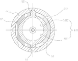
- 6A is a cross-sectional view showing the first embodiment of the electronic device carrying clip of the electronic device of the present invention rotated into a gear position.
- 6B is a cross-sectional view showing the state in which the elastic piece of the first preferred embodiment of the electronic device carrying clip of the electronic device of the present invention is rotated in an unshifted position.
- FIG. 7 is a cross-sectional view of a spring piece, a snap ring, and a groove of a second preferred embodiment of the electronic device carrying clip of the present invention.
- FIG. 8 is a cross-sectional view of a spring piece, a snap ring, and a groove of a third preferred embodiment of the electronic device carrying clip of the present invention.
- 9A is a front elevational view of a spring piece of a fourth preferred embodiment of the electronic device carrying clip of the present invention.
- FIG. 9B is a side view of the elastic piece of the fourth preferred embodiment of the electronic device carrying clip of the present invention.
- FIG. 10 is a cross-sectional view showing the elastic piece of the fifth embodiment of the electronic device carrying clip of the present invention, and the snap ring and the groove.
- FIG. 11 is a cross-sectional view of a resilient piece of a sixth preferred embodiment of the electronic device carrying clip of the present invention, with a snap ring and a recess.
- the reference numerals are as follows: 2a, housing body; 21a, back clip; 211a, card slot; 3a, rivet; 4a, belt buckle; 41a, bracket; 411a limit protrusion; 6a, positive pressure spring; Colloid; 21, snap ring; 211, notch; 212, limit slot; 213, limit block; 22, first fixed pin; 23, receiving groove; 24, receiving cavity; 4, second body; Belt buckle; 412, bracket; 413, boss; 42, second fixing pin; 44, groove; 441, card slot; 6, elastic piece; 61, shrapnel body; 611, inner wall surface; 6111, circular wall surface; , elliptical wall surface; 612 outer wall surface; 62, protrusion; 63, limit block.
- the electronic device carrying clip of the first embodiment of the present invention comprises: a first clamping body 2, a second clamping body 4 and a spring piece 6.
- the electronic device of the present invention may be a walkie-talkie, a mobile phone, or other types of electronic devices in practical applications, and is not specifically limited herein.
- any one of the first body 2 and the second body 4 can be used as a casing body for accommodating the electronic device, and the other can be used as a belt clip to fix the electronic device to the belt when not in use, thereby increasing The portability of electronic devices.
- the first body 2 is used as a housing body for housing the electronic device, and a housing chamber 24 for accommodating the electronic device is disposed thereon.
- the second body 4 is used as a belt clip, and includes a belt buckle 411 and a bracket 412.
- the belt buckle 411 and the bracket 412 are hingedly connected by a pin shaft, and a torsion spring is sleeved on the pin shaft to elastically clamp the belt buckle 411.
- a torsion spring is sleeved on the pin shaft to elastically clamp the belt buckle 411.
- the first body 2 and the second body 4 are rotatably connected.
- the first clamping body 2 is provided with a through hole, and a first fixing pin 22 is mounted in the through hole, and a through hole is also disposed in the bracket 412 of the second clamping body 4, and a second fixing is installed in the through hole.
- the pin 42, the bracket 412 of the first body 2 and the second body 4 are rotatably assembled by the first fixing pin 22 and the second fixing pin 42 fixed together, the first fixing pin 22 and the second fixing pin 42 is butted into a central rotating shaft, so that both the first body 2 and the second body 4 can rotate about the central axis.
- the rotatably connected structure of the first body 2 and the second body 4 is not limited to the fixed pin connection form, and the matching structure of the fixing column and the through hole, or the cooperation structure of the bolt and the through hole may be adopted.
- the rotatably connected structure can be formed between the first body 2 and the second body 4 in a manner that is well known in the prior art, and is not specifically limited herein.
- a snap ring 21 is disposed on the first clamping body 2, and a notch 211 is defined in the snap ring 21.
- the second body 4 is provided with a groove 44, and a plurality of card grooves 441 are uniformly formed on the wall surface of the groove 44.
- a bracket 412 is disposed on the bracket 412 of the second body 4, and a groove 44 is formed on the boss 413.
- the first body 2 is recessed downward on a side facing the second body 4 for forming
- the accommodating groove 23 accommodating the boss 413 is located in the accommodating groove 23.
- the elastic piece 6 is made of an elastic plastic material, and includes an annular elastic body 61 and a protrusion 62 protruding from the elastic body 61.
- the snap ring 21 of the first body 2 is snapped into the groove 44 of the second body 4 and can be along The wall surface of the groove 44 is rotated, and the elastic body 61 is engaged in the snap ring 21 of the first body 2, and the upper protrusion 62 extends beyond the notch 211 of the snap ring 21 and is opposite to the wall surface of the groove 44 of the second body 4. conflict.
- the protrusion 62 of the elastic piece 6 is along the groove 44.
- the wall is rotated so as to alternately interfere with the slot 441 or the non-slot of the wall of the recess 44.
- the projection 62 is rotated to the non-slot between the two slots 441, the projection 62 is recessed 44.
- the wall is pressed and deformed toward the inner cavity of the snap ring 21.
- the elastic piece 6 is in a pre-stressed state, and the pressing force between the protrusion 62 and the wall surface of the groove 44 is large, so that the pressing force is overcome to drive the first
- the external force consumed by the relative rotation of the body 2 and the second body 4 is also large; when the protrusion 62 is further rotated to the position of the next card slot 441, the elastic piece 6 naturally elongates under the action of its own elastic force, and the elastic force of the elastic piece 6 is affected by the elastic force of the elastic piece 6
- the self-deformation recovers and gradually weakens, so that the pressing force between the protrusion 62 and the wall surface of the groove 44 is gradually weakened, so that the relative rotation of the first body 2 and the second body 4 against the pressing force is utilized.
- the protrusions 62 can be formed into a layered or non-slotted position along the wall surface of the groove 44, thereby forming a layered hand. Get a sense of gear.
- the elastic force of the elastic piece 6 depends on the material of the elastic piece 6 on the one hand, and on the other hand, the shape of the elastic piece 6 and the degree of deformation of the elastic piece 6 during the rotation, and thus the material of the elastic piece 6 and
- the elastic force of the elastic piece 6 depends only on the degree of deformation of the elastic piece 6 during the rotation, and the degree of deformation of the elastic piece 6 during the rotation depends on the shape of the groove 44, and thus the shape of the groove 44 When determined, the elastic force of the elastic piece 6 is determined.
- the shape of the elastic piece 6, the shape of the elastic piece 6, and the shape of the groove 44 are not affected by the assembly process of the product, so that the assembly process of the product does not affect the elastic force of the elastic piece 6, so that the rotational torque is easy to control without being affected by the assembly process, and all the operations are ensured.
- the product's rotational torsion is consistent, avoiding the phenomenon of large or small rotating torque of different products.
- the flexible plastic material shrapnel 6 has good toughness, good wear resistance and long service life. Even if it is used for a long time, it will not cause too much change in the elasticity of the elastic piece 6, so that the electronic device carrying clip can maintain a constant and constant rotation. Torque.
- the material of the elastic piece 6 is made of PC material, that is, polycarbonate, which has high strength, elastic modulus, high impact strength and the like, has good fatigue resistance and long service life, and can hold the electronic device carrying clips. Long lasting constant rotational torque.
- the material of the elastic piece 6 can also be PC/ABS material, which is a mixture of PC and ABS materials, PC is polycarbonate, ABS is acrylonitrile (A), butadiene (B) and The copolymer of styrene (S), PC/ABS material has better flexibility, impact resistance, higher hardness and long service life.
- the elastic piece 6 can also be made of PA material, that is, the polyamide is commonly known as nylon, and the PA material has good abrasion resistance, good self-lubricating property, low friction coefficient, and smooth sliding when used as a shrapnel, and the user experience is good.
- PA material that is, the polyamide is commonly known as nylon
- the PA material has good abrasion resistance, good self-lubricating property, low friction coefficient, and smooth sliding when used as a shrapnel, and the user experience is good.
- the material of the elastic piece 6 can be other known elastic plastic materials in the prior art, and it is not exhaustive here.
- the first body 2 and the second body 4 are also made of plastic material, so that the elastic piece 6 is substantially the same material as the first body 2 and the second body 4, and the hardness is substantially equal, and the elastic piece 6 and the concave are avoided.
- the wall surfaces of the grooves 44 wear against each other to reduce the smoothness of the sliding of the elastic piece 6.
- the material of the elastic piece 6, the first clamping body 2 and the second clamping body 4 are all made of plastic material, and the corrosion is not corroded even after long-term contact with water stains and perspiration, so that the appearance can be kept novel and beautiful for a long time.
- a limiting structure for restricting relative rotation of the elastic body 61 and the snap ring 21 is disposed between the portion of the elastic body 61 away from the protrusion 62 and the snap ring 21 , and the limiting structure and the snap ring 21 are The notch 211 respectively limits the two ends of the elastic piece 6 to prevent the elastic piece 6 from rotating relative to the snap ring 21, thereby causing the elastic deformation of the elastic piece 6, which affects the elasticity and even causes the rotation to be stuck.
- the limiting structure for restricting the relative rotation of the elastic body 61 and the snap ring 21 may be configured as follows: a mounting hole is disposed between the portion of the elastic body 61 away from the protrusion 62 and the snap ring 21, and the elastic body 61 is away from the convex body. The portion of the portion 62 and the snap ring 21 are fixed by fasteners such as screws and bolts.
- the limiting structure for restricting the relative rotation of the elastic body 61 and the snap ring 21 includes: a matching limiting groove 64 and a limit respectively disposed between the elastic body 61 and the snap ring 21 Bit block 213.
- the limiting slot 64 can be disposed on the spring body 61, and the limiting block 213 is disposed on the snap ring 21.
- the limiting groove 64 may also be disposed on the snap ring 21, and the limiting block 213 may be disposed on the elastic body 61.
- a plurality of pairs of limiting slots 64 and limiting blocks 213 may be added to limit the elastic piece 6 and the snap ring. 21 relative rotation.
- the limiting structure for restricting the relative rotation of the elastic body 61 and the snap ring 21 includes: mutually matching limiting slots respectively disposed between the elastic body 61 and the snap ring 21 . 212 and a limiting block 63, the limiting block 63 is disposed on the elastic body 61 and located at a relative position of the protrusion 62.
- the limiting slot 212 forms a snap ring 21 and is located at a relative position of the notch 211, and the limiting slot 212 passes through the card.
- the ring 21 is such that the snap ring 21 is divided by the notch 211 and the limiting groove 212 into two oppositely distributed circular arcs.
- the thickness of the portion of the elastic body 61 near the protrusion 62 is uniformly thinned according to the distance from the protrusion 62, so that the elastic piece 6 is more favorable for deformation and reduces the rotational torque. Make user operations easier. Further, the material thickness (material thickness) of the portion of the elastic body 61 close to the projection 62 is uniformly thinned from the far side to the vicinity of the projection 62, and the elastic piece 6 can be deformed only when the elastic body 61 is close.
- the portion of the protrusion 62 is locally deformed, and the portion of the elastic body 61 away from the protrusion 62 is hardly deformed due to the wide material thickness, so that the elastic body 61 can maintain the overall shape during the rotation to avoid excessive deformation. Causes unstable rotation torque.
- the thickness of the portion of the elastic body 61 near the protrusion 62 is uniformly thinned from far to near according to the distance from the protrusion 62.
- the structure is realized by the following structure: the elastic body 61 is an eccentric ring.
- the inner wall surface 611 and the outer wall surface 612 are both circular, the outer wall surface 612 has a radius R1, the inner wall surface 611 has a radius R2, the inner wall surface 611 has a center that is offset from the center of the outer wall surface 612, and the inner wall surface 611 has a center along the outer wall surface.
- the line connecting the center of the center 612 and the center of the protrusion 62 is offset from the center of the outer wall surface 612, so that the thickness of the spring body 61 is uniformly thinned from the distal end of the protrusion 62 toward the proximal end of the protrusion 62, thereby avoiding uneven thickness.
- stress concentration occurs in the elastic piece 6, which in turn causes breakage, and the portion of the elastic piece 6 near the protrusion 62 is more easily deformed, which reduces the rotational torque and makes the user's operation easier.
- the eccentricity of the elastic body 61 is preferably in the range of 2% to 10%, so as to ensure that the elastic force of the elastic piece 6 is moderate, so that the user has an obvious gear feeling when operating, and does not feel the rotation due to too much torque.
- Hard work Specifically, in the present embodiment, the radius R2 of the inner wall surface 611 of the elastic body 61 is about 14.5 mm, the radius R1 of the outer wall surface 612 is about 18 mm, and the distance C of the inner wall surface 611 from the center of the outer wall surface 612 is about 0.7 mm.
- the uniform thickness variation of the elastic body 61 can also be achieved by the following structure.
- the outer wall surface 612 of the elastic body 61 is a circular surface, and the inner wall surface 611 of the elastic body 61 is close to the projection 62.
- the half wall surface is an elliptical wall surface 6112, and the half wall surface away from the protrusion 62 is a circular wall surface 6111, and the short axis of the elliptical wall surface 6112 is equal to the radius of the circular wall surface 6111 so that the elliptical wall surface 6112 and the circle are rounded.
- the wall 6111 has a smooth transition. This structure also makes it easier to deform the portion of the elastic piece 6 near the projection 62, making the user's operation easier.
- the uniform thickness variation of the elastic body 61 can also be achieved by the following structure.
- the inner wall surface 611 and the outer wall surface 612 of the elastic body 61 are both elliptical surfaces, and the center of the inner wall surface 611 is oriented.
- the direction of the protrusion 62 is offset from the center of the outer wall surface 612, and the center of the inner wall surface 611 is located on the line connecting the center of the outer wall surface 612 and the center of the protrusion 62.
- the long axis of the outer wall surface 612 is located at the center of the outer wall surface 612 and the center of the protrusion 62.
- the short axis of the outer wall surface 612 is perpendicular to the outer wall surface
- the center of the 612 is connected with the center of the protrusion 62
- the positions of the two ends of the long axis of the elastic piece body 61 can fully satisfactorily contact the snap ring 21, and the protrusion 62 on the elastic piece 6 is
- the notch 211 of the snap ring 21 protrudes to interfere with the wall surface of the groove 44, and the short axis position of the elastic body 61 forms a gap 214 with the snap ring 21, and the gap 214 provides orientation and quantification for the deformation of the elastic piece 6.
- the deformation space makes the elastic force change of the elastic piece 6 during the rotation process more regular and stable, thereby obtaining a more regular and stable rotational torque and improving the user experience.
- the thickness variation of the elastic body 61 is reflected in the thickness variation between the inner wall surface 611 and the outer wall surface 612 of the elastic body 61.
- the change in the thickness of the elastic body 61 may also be reflected in the thickness variation of the inner wall surface 611 and the outer wall surface 612 of the elastic body 61 in the surface width direction.
- FIG. 9A is a front view of the elastic piece 6, and FIG. 9B is a side view of the elastic piece 6.
- the inner wall surface 611 and the outer wall surface 612 of the elastic piece body 61 of the elastic piece 6 are concentric rings, and The thickness of the elastic body 61 along the surface width direction of the inner wall surface 611 or the outer wall surface 612 of its own is thinned uniformly from the portion away from the projection 62 toward the portion near the projection 62.
- the protrusion 62 on the elastic piece 6 is also a thickness gradient structure, and the root portion of the protrusion 62 connected to the elastic piece body 61 is evenly thinned toward the outer end direction, and is also disposed on the elastic body.
- Other structures on 61 such as the limiting block 63 disposed on the opposite side of the projection 62, are also thickness-graded structures which continue the thickness variation of the elastic body 61 from the root of the limiting block 63 and the elastic body 61.
- the end direction is evenly thickened.
- the elastic structure of this embodiment can also make it easier to deform the portion of the elastic piece 6 near the projection 62, and the user can rotate more easily.
- the material thickness of the portion of the elastic piece body 61 near the protrusion 62 is uniformly thinned from far to near according to the distance from the protrusion 62.
- this is not a preferred embodiment of the present invention, but it is not In the actual application, since the elastic body 61 is made of an elastic plastic material, even if the elastic body 61 has a uniform thickness, the elastic deformation requirement of the present invention can be satisfied.
- the non-slotted position of the wall surface of the groove 44 is a plurality of arc surfaces of the same concentricity and the same radius, and all the walls of the slot 441 are arcs of the same size.
- the shape of the arc, and the center of the arc of the groove 44 at the non-slot position is merged with the center of the elastic body 61 at the center of rotation of the first body 2 and the second body 4, so that the spring 6 is rotated to make the protrusion 62
- the elastic force of the elastic piece 6 is constant, and the hand feeling obtained when the user rotates the experience is the same, and when the elastic piece 6 is rotated to the groove All card slots of 44 At 441 positions, the force is also the same, so the user experience is the same, so that when the elastic piece 6 rotates and alternates with the groove 441 of the wall surface of the groove 44 or the non-slot position, the regular pattern can be formed.
- the wall surface of the recess 44 has a card slot 441 at every 45 degree angle to obtain a gear position at every 45 degree angle.
- the number of slots 441 can be adjusted accordingly depending on the number of gear positions required.
- the wall surface of the groove 44 may also be a polygonal surface, and the wall surface of each side of the polygonal surface is a circular arc surface arched toward the center of the groove 44 and adjacent thereto.
- the interface between the two sides forms a card slot 441.
- the wall shape of the groove 44 and the slot 441 is only a preferred embodiment of the present invention, but not limited thereto, and the wall surface of the groove 44 and the wall surface of the slot 441 may be any The shape in which the elastic piece 6 can be rotated therein is not exhaustive here.
Landscapes
- Engineering & Computer Science (AREA)
- Signal Processing (AREA)
- Computer Networks & Wireless Communication (AREA)
- Microelectronics & Electronic Packaging (AREA)
- Clamps And Clips (AREA)
- Casings For Electric Apparatus (AREA)
Abstract
一种电子设备携带夹,包括:第一夹体(2)、第二夹体(4)以及弹片(6),第一夹体(2)设置卡环(21)且卡环(21)上开设缺口(211);第二夹体(4)与第一夹体(2)可转动相连,第二夹体(4)设置有凹槽(44),第一夹体(2)的卡环(21)卡装在第二夹体(4)的凹槽(44)中并可沿着凹槽(44)的壁面旋转,且凹槽(44)的壁面上均匀形成有多个卡槽(441);弹片(6)包括环形的弹片本体(61)和凸设在弹片本体上的凸起(62),弹片本体(61)卡装在第一夹体(2)的卡环(21)中,凸起(62)伸出卡环(21)的缺口(211)并与第二夹体(4)的凹槽(44)壁面相抵触;当第一夹体(2)与第二夹体(4)相对旋转时,弹片(6)的凸起(62)沿着凹槽(44)的壁面旋转而交替与凹槽(44)壁面的卡槽位或非卡槽位相抵触而形成档位。该电子设备携带夹结构简单,成本低,旋转扭力易控,便于装配,且弹片采用塑胶材料,即便长期使用也能保持持久恒定的旋转扭力。
Description
本发明涉及电子产品领域,尤其涉及一种电子设备携带夹。
随着电子设备(如对讲机等)的不断普及,用户对电子设备的便携性提出了越来越高的要求。
现有技术中,很多便携式电子设备,如对讲机,为了方便携带一般都配备有携带夹。携带夹通常包括:用于卡装对讲机的外壳主体以及安装在外壳主体上的皮带扣,该皮带扣可以挂接在皮带上,从而使电子设备在不使用时固定在皮带上,增加电子设备的便携性。
而电子设备往往具有相当长度,特别对讲机等电子设备还配备有天线,因而长度会更大,当固定在腰间皮带上,如果使用者弯腰或蹲下,电子设备或天线会碰到使用者的身体,让使用者感到不适。
对此,可旋转式携带夹应运而生,参阅图1,现有技术中的可旋转式携带夹的皮带扣4a上安装有支架41a,外壳主体2a上固定有背夹21a,背夹21a与支架41a上对应设置铆孔,二者通过铆钉3a铆合组装而可相对转动,同时在支架41a面向背夹21a一面的铆孔周围每隔45度设置一圆形的限位凸起411a,在背夹21a面向支架41a一侧的铆孔周围每隔45度设置一圆形的卡槽211a,支架41a上的多个限位凸起411a对应卡入背夹21a上的多个卡槽211a内,所述支架41a背对凸起411a的另一侧设置有正压弹片6a,正压弹片6a的两侧拱起,因而当固定正压弹片6a的铆钉压紧正压弹片6a时,正压弹片6a将产生弹力,将支架上的限位凸起411a以一定的预应力压在背夹21a的卡槽211a中,当施以一定外力克服正压弹片6a的弹力而转动外壳主体2a时,支架41a上的限位凸起411a与背夹21a上的卡槽211a脱开,当限位凸起411a转动至下一卡槽211a时,由于正压弹片6a的弹性施压,使限位凸起411a轻松滑入下一卡槽211a,产生档位感。
然而,这种采用正压弹片铆合组装的携带夹结构复杂,成本高,而且由于该携带夹主要依靠正压弹片表面的拱起部位获得预应力,而拱起部位的预应力取决于铆钉铆接的松紧度,因而装配过程中松紧度掌握稍有偏差,便会出现旋转扭力或大或小的现象,导致旋转扭力很难掌控,极大地影响了用户体验。
发明内容
本发明要解决的技术问题在于提供一种结构简单、成本低且旋转扭力易掌控的电子设备携带夹。
为解决上述技术问题,本发明提出一种电子设备携带夹,包括:
第一夹体,其上设置卡环,且卡环上开设缺口;
第二夹体,与所述第一夹体可转动相连,所述第二夹体上设置有凹槽,所述第一夹体的卡环卡装在所述第二夹体的凹槽中并可沿着所述凹槽的壁面旋转,且所述凹槽的壁面上均匀形成有多个卡槽;以及
弹片,包括:环形的弹片本体和凸设在所述弹片本体上的凸起,所述弹片本体卡装在所述第一夹体的卡环中,所述凸起伸出所述卡环的缺口并与所述第二夹体的凹槽壁面相抵触;
所述弹片为弹性塑胶材质,当所述第一夹体与所述第二夹体相对旋转时,所述弹片的凸起沿着所述凹槽的壁面旋转而交替与所述凹槽壁面的卡槽位或非卡槽位相抵触而形成档位。
更优地,所述弹片本体靠近凸起的部位的料厚根据其与所述凸起的距离由远至近均匀变薄。
更优地,所述弹片本体为偏心环,其内壁面和外壁面均呈圆形,所述内壁面的圆心向靠近凸起的方向偏离所述外壁面的圆心并位于所述外壁面圆心与所述凸起中心的连线上。
更优地,所述弹片本体的偏心率在2%-10%区间范围。
更优地,所述弹片本体的外壁面为圆形面,所述弹片本体内壁面的靠近所述凸起的半个壁面为椭圆形壁面,远离所述凸起的半个壁面为圆形壁面,所述内壁面的椭圆形壁面和圆形壁面平滑过渡。
更优地,所述弹片本体的内壁面和外壁面均为椭圆形面,所述内壁面的
中心向靠近凸起的方向偏离所述外壁面的中心并位于所述外壁面中心与所述凸起中心的连线上,所述外壁面的长轴位于所述外壁面中心与所述凸起中心的连线上,所述外壁面的短轴垂直于所述外壁面中心与所述凸起中心的连线。
更优地,所述弹片本体的内壁面和外壁面为共心圆环,且所述弹片本体沿其自身的内壁面或外壁面的面宽方向的厚度由远离凸起的部位向靠近凸起的部位均匀变薄。
更优地,所述弹片本体远离所述凸起的部位与所述卡环之间设置有限制所述弹片本体与所述卡环相对转动的限位结构。
更优地,所述限位结构包括:分别设置在所述弹片本体和所述卡环之间的相互配合的限位槽和限位块。
更优地,所述限位块设置在所述弹片本体上并位于所述凸起的相对位置,所述限位槽形成卡环上并位于所述缺口的相对位置,且所述限位槽贯通所述卡环,使得所述卡环被所述缺口和所述限位槽分隔成两个相对分布的圆弧瓣。
更优地,所述凹槽壁面的非卡槽位置为多段同心且半径相同的圆弧面,所有卡槽的壁面均为大小相同的弧形面,且所述凹槽的非卡槽位置的圆弧中心与所述弹片本体的中心重合并位于所述第一夹体和所述第二夹体的旋转中心位置。
更优地,所述第一夹体和所述第二夹体均为塑胶材质。
与现有技术相比,本发明具有如下有益效果:
本发明的电子设备携带夹利用弹片的凸起与带多个卡槽位的凹槽壁面相抵触,使弹片交替受到不同程度的压缩,形成层次分明的档位感,不仅结构简单,成本低,而且弹片的弹力大小与其自身的形状、材质以及凹槽的形状有关,与装配过程无关,因而旋转扭力易控,避免因装配问题而导致同种产品旋转扭力参差不齐的现象;此外,由于弹片为弹性塑胶材质,因而韧性较好,耐磨性好,寿命长,使该电子设备携带夹保持持久恒定的旋转扭力。
图1为现有技术中的一种电子设备携带夹的结构爆炸图。
图2为本发明电子设备携带夹第一较佳实施例的整体结构示意图。
图3为本发明电子设备携带夹第一较佳实施例的爆炸图一。
图4为本发明电子设备携带夹第一较佳实施例的爆炸图二。
图5为本发明电子设备携带夹第一较佳实施例的爆炸图三。
图6A为本发明电子设备携带夹第一较佳实施例的弹片旋转至一档位中的截面图。
图6B为本发明电子设备携带夹第一较佳实施例的弹片旋转在未入档位状态的截面图。
图7为本发明电子设备携带夹第二较佳实施例的弹片与卡环和凹槽的配合截面图。
图8为本发明电子设备携带夹第三较佳实施例的弹片与卡环和凹槽的配合截面图。
图9A为本发明电子设备携带夹第四较佳实施例的弹片的主视图。
图9B为本发明电子设备携带夹第四较佳实施例的弹片的侧视图。
图10为本发明电子设备携带夹第五较佳实施例的弹片与卡环和凹槽的配合截面图。
图11为本发明电子设备携带夹第六较佳实施例的弹片与卡环和凹槽的配合截面图。
附图标号说明如下:2a、外壳主体;21a、背夹;211a、卡槽;3a、铆钉;4a、皮带扣;41a、支架;411a限位凸起;6a、正压弹片;2、第一夹体;21、卡环;211、缺口;212、限位槽;213、限位块;22、第一固定销;23、容纳槽;24、容纳腔;4、第二夹体;411、皮带扣;412、支架;413、凸台;42、第二固定销;44、凹槽;441、卡槽;6、弹片;61、弹片本体;611、内壁面;6111、圆形壁面;6112、椭圆形壁面;612外壁面;62、凸起;63、限位块。
为了进一步说明本发明的原理和结构,现结合附图对本发明的较佳实施例进行详细说明。
参阅图2、图3、图4和图5,本发明第一实施例的电子设备携带夹包括:第一夹体2、第二夹体4以及弹片6。
本发明的电子设备在实际应用中可以为对讲机、移动电话,或其他类型的电子设备,此处不作具体限定。
第一夹体2和第二夹体4的任意一者均可作为用于卡装容纳电子设备的外壳主体,另一者可作为皮带夹,使电子设备在不使用时固定在皮带上,增加电子设备的便携性。
在本实施例将第一夹体2作为卡装容纳电子设备的外壳主体,其上设置有用以容纳电子设备的容纳腔24。第二夹体4作为皮带夹,其包括:皮带扣411和支架412,皮带扣411与支架412通过销轴铰接连接,并在销轴上套设有扭簧,以将皮带扣411弹性夹持在支架412上。
第一夹体2与第二夹体4可转动相连。
具体地,第一夹体2设置一通孔,并在通孔中安装有第一固定销22,第二夹体4的支架412上也设置一通孔,并在该通孔中安装有第二固定销42,第一夹体2和第二夹体4的支架412通过第一固定销22与第二固定销42对接固定而可转动地组装在一起,该第一固定销22和第二固定销42则对接成中心转轴,使第一夹体2和第二夹体4均可绕该中心转轴转动。
在其他实施例中,第一夹体2和第二夹体4的可转动连接结构不限于固定销连接形式,也可以采用固定柱与通孔的配合结构,或者螺栓与通孔的配合结构等。
可以理解的是,在实际应用中,第一夹体2和第二夹体4之间还可以采用现有技术公知的更多方式构成可转动连接结构,此处不做具体限定。
第一夹体2上设置有卡环21,卡环21上开设缺口211。
第二夹体4上设置有凹槽44,凹槽44的壁面上均匀形成有多个卡槽441。
进一步地,第二夹体4的支架412上设置有凸台413,凹槽44形成在该凸台413上;第一夹体2于面向第二夹体4的一侧向下凹陷形成用以容纳凸台413的容纳槽23,卡环21位于该容纳槽23内。
弹片6为弹性塑胶材质,其包括:环形的弹片本体61和凸设在弹片本体61上的凸起62。
参阅图6A和图6B,当第一夹体2和第二夹体4组装在一起时,第一夹体2的卡环21卡装在第二夹体4的凹槽44中并可沿着凹槽44的壁面旋转,弹片本体61卡装在第一夹体2的卡环21中,其上凸起62伸出卡环21的缺口211并与第二夹体4的凹槽44壁面相抵触。
当第一夹体2与第二夹体4相对旋转时,弹片6的凸起62沿着凹槽44
的壁面旋转,使其交替与凹槽44壁面的卡槽441位或非卡槽位相抵触,当凸起62旋转至两卡槽441之间的非卡槽位时,凸起62被凹槽44壁面挤压而向卡环21内腔方向变形,此时,弹片6处于预压状态,凸起62与凹槽44壁面之间的挤压力较大,因而要克服该挤压力而带动第一夹体2与第二夹体4相对旋转所耗费的外力也较大;当凸起62进一步旋转至下一个卡槽441位时,弹片6在自身弹力作用下自然伸长,弹片6弹力受自身变形恢复而逐渐减弱,因而凸起62与凹槽44壁面之间的挤压力也逐渐减弱,从而使克服该挤压力而带动第一夹体2与第二夹体4相对旋转所耗费的外力也逐渐减弱。因而当第一夹体2与第二夹体4相对转动时,随着凸起62交替与凹槽44壁面的卡槽441位或非卡槽位相抵触,便可形成层次分明的手感,以此获得档位感。
由于弹片6为弹性塑胶材质,弹片6的弹力一方面取决于弹片6本身的材质,另一方面还取决于弹片6的形状和弹片6在旋转过程中的变形程度,因而在弹片6的材质和弹片6形状确定的前提下,弹片6的弹力只取决于弹片6在旋转过程中的变形程度,而弹片6在旋转过程中的变形程度则取决于凹槽44的形状,因此在凹槽44形状确定时,弹片6的弹力是确定的。而弹片6材质、弹片6形状和凹槽44形状是不受产品装配过程影响的,因而产品装配过程不会影响弹片6的弹力,使得旋转扭力易控而不受装配过程影响,也确保了所有产品的旋转扭力一致,避免出现不同产品旋转扭力或大或小的现象。
其次,弹性塑胶材质的弹片6韧性较好,耐磨性好,寿命长,即便长时间使用,也不会导致弹片6弹性发生太大变化,因而能够使该电子设备携带夹保持持久恒定的旋转扭力。
在本实施例中,弹片6的材质为PC材质,即聚碳酸酯,其具高强度及弹性系数、高冲击强度等特性,耐疲劳性佳,使用寿命长,能够使该电子设备携带夹保持持久恒定的旋转扭力。在其他实施例中,弹片6的材质也可以为PC/ABS材质,其为PC和ABS两种材料的混合物,PC就是聚碳酸脂,ABS就是丙烯腈(A)、丁二烯(B)和苯乙烯(S)的共聚物,PC/ABS材质柔韧性更好,抗冲击性、硬度更高,使用寿命长。此外,弹片6还可以为PA材质,即,聚酰胺俗称尼龙,PA材质耐磨损性好,自润性好,摩擦系数低,作为弹片使用时,滑动顺畅,用户体验好。
可以理解的是,在实际应用中,弹片6的材质可以是现有技术中其他公知的弹性塑胶材质,此处不作一一穷举。
更优地,第一夹体2和第二夹体4也为塑胶材质,以使弹片6与第一夹体2、第二夹体4的材质大致相同,硬度基本相当,避免弹片6与凹槽44壁面相互磨损而降低弹片6滑动的顺畅度。其次,弹片6、第一夹体2、第二夹体4的材质均为塑胶材质,即便长期接触水渍、汗渍也不会发生腐蚀,因而能够长期保持外形新颖、美观。
在较优的实施方式中,弹片本体61远离凸起62的部位与卡环21之间还设置有限制弹片本体61与卡环21相对转动的限位结构,该限位结构与卡环21的缺口211分别对弹片6两端构成限位,防止弹片6与卡环21发生相对转动,进而造成弹片6扭曲变形,影响弹力稳定,甚至造成旋转卡死现象。
在具体实施时,限制弹片本体61与卡环21相对转动的限位结构可以为如下结构:在弹片本体61远离凸起62的部位与卡环21之间设置安装孔,将弹片本体61远离凸起62的部位与卡环21通过螺钉、螺栓等紧固件固定在一起。
参阅图10,在较优的实施方式中,限制弹片本体61与卡环21相对转动的限位结构包括:分别设置在弹片本体61和卡环21之间的相互配合的限位槽64和限位块213。实际应用中,限位槽64可设置在弹片本体61上,限位块213设置在卡环21上。也可将限位槽64设置在卡环21上,而将限位块213设置在弹片本体61上。此外,一对限位槽64和限位块213限制弹片6与卡环21相对转动的限位强度不够时,也可增设多对限位槽64和限位块213来限制弹片6与卡环21相对转动。
参阅图6A和图6B,在更优的实施方式中,限制弹片本体61与卡环21相对转动的限位结构包括:分别设置在弹片本体61和卡环21之间的相互配合的限位槽212和限位块63,限位块63设置在弹片本体61上并位于凸起62的相对位置,限位槽212形成卡环21上并位于缺口211的相对位置,且限位槽212贯通卡环21,使得卡环21被缺口211和限位槽212分隔成两个相对分布的圆弧瓣。
在较优的实施方式中,弹片本体61靠近凸起62部位的料厚根据其与凸起62的距离由远至近而均匀变薄,从而使弹片6更利于变形,减小旋转扭力,
使用户操作更轻松。此外,弹片本体61靠近凸起62的部位的料厚(用料厚度)根据其与凸起62的距离由远至近而均匀变薄,还能够使弹片6在变形时,只在弹片本体61靠近凸起62的部位发生局部变形,而弹片本体61远离凸起62的部位则由于料厚较宽而几乎不发生变形,因而能够使弹片本体61在旋转过程中保持整体外形,避免变形过大而造成旋转扭力不稳定的现象。
参阅图6A,在较优的实施方式中,弹片本体61靠近凸起62部位的料厚根据其与凸起62的距离由远至近而均匀变薄通过如下结构实现:弹片本体61为偏心环,其内壁面611和外壁面612均为圆形,外壁面612的半径为R1,内壁面611的半径为R2,内壁面611的圆心偏离外壁面612的圆心,且内壁面611的圆心沿外壁面612圆心与凸起62中心的连线方向偏离外壁面612的圆心,使得弹片本体61的料厚由凸起62的远端向凸起62的近端方向均匀变薄,避免料厚不均匀而导致弹片6出现应力集中,进而导致断裂,也使得弹片6靠近凸起62的部位更容易变形,减小了旋转扭力,使用户操作更轻松。
进一步地,弹片本体61的偏心率优选在2%-10%区间范围内,以确保弹片6弹力适度,使用户操作时,既有明显的档位感,又不会因扭力太大而感觉旋转吃力。具体地,在本实施例中,弹片本体61内壁面611的半径R2约为14.5mm,外壁面612的半径R1约为18mm,内壁面611圆心偏离外壁面612圆心的距离C约为0.7mm,该弹片本体61的偏心率=E=C/R1=3.89%。
在另一个实施例中,弹片本体61的料厚均匀变化方案也可通过如下结构实现,参阅图7,弹片本体61的外壁面612为圆形面,弹片本体61内壁面611的靠近凸起62的半个壁面为椭圆形壁面6112,远离凸起62的半个壁面为圆形壁面6111,椭圆形壁面6112的短轴与圆形壁面6111的半径相等,以使该椭圆形壁面6112和圆形壁面6111平滑过渡。该结构也能使弹片6靠近凸起62的部位容易更变形,使用户操作更轻松。
在另一个实施例中,弹片本体61的料厚均匀变化方案还可通过如下结构实现,参阅图8,弹片本体61的内壁面611和外壁面612均为椭圆形面,内壁面611的中心向靠近凸起62的方向偏离外壁面612的中心,且内壁面611的中心位于外壁面612中心与凸起62中心的连线上,外壁面612的长轴位于外壁面612中心与凸起62中心的连线上,外壁面612的短轴垂直于外壁面
612中心与凸起62中心的连线,使得弹片6卡装与卡环21中时,弹片本体61长轴的两端位置能够饱满抵触于卡环21,并使弹片6上的凸起62从卡环21的缺口211处伸出而与凹槽44的壁面相抵触,而弹片本体61短轴位置则与卡环21之间形成空隙214,该空隙214为弹片6的变形提供了定向和定量的变形空间,使弹片6在旋转过程中的弹力变化更规律、稳定,以此获得更规律稳定的旋转扭力,提升用户的体验感。
在图6A、图6B、图7和图8所示的三个实施例中,弹片本体61的料厚变化均体现在弹片本体61的内壁面611与外壁面612之间的厚度变化。在其他实施例中,弹片本体61的料厚变化也可体现在弹片本体61的内壁面611和外壁面612的面宽方向的厚度变化。
如图9A和图9B所示,如图9A为弹片6的主视图,图9B为弹片6的侧视图,该弹片6的弹片本体61的内壁面611和外壁面612为共心圆环,且弹片本体61沿其自身的内壁面611或外壁面612的面宽方向的厚度由远离凸起62的部位向靠近凸起62的部位均匀变薄。为了保持弹片6整体外观的一致性,弹片6上的凸起62也为厚度渐变结构,其由凸起62与弹片本体61连接的根部位置向外端方向均匀变薄,同样,设置在弹片本体61上的其他结构,如设置在凸起62相对侧的限位块63也为厚度渐变结构,其延续弹片本体61的厚度变化趋势,从限位块63与弹片本体61连接的根部位置向外端方向均匀变厚。同样,该实施例的弹片结构也能使弹片6靠近凸起62的部位变形更容易,用户旋转更轻松。
需要说明的是,上文中弹片本体61靠近凸起62的部位的料厚根据其与凸起62的距离由远至近均匀变薄的方案仅为本发明的较佳实施方式,但并非以此为限,实际应用时,由于弹片本体61为弹性塑胶材质,因而即便弹片本体61料厚均匀的情形,一样能满足本发明的弹性变形要求。参阅图6A、图6B和图7,在较优的实施方式中,凹槽44壁面的非卡槽位置为多段同心且半径相同的圆弧面,所有卡槽441的壁面均为大小相同的弧形面,且凹槽44非卡槽位置的圆弧中心与弹片本体61的中心重合并位于第一夹体2和第二夹体4的旋转中心位置,因而当弹片6旋转而使凸起62与凹槽44壁面的任意非卡槽位置接触时,其受力都是相同的,因而弹片6的弹力是恒定的,用户旋转体验时获得的手感也是相同的,而当弹片6旋转至凹槽44的所有卡槽
441位时,其受力也是相同的,因而用户体验的手感也是相同的,从而当弹片6旋转而交替与凹槽44壁面的卡槽441位或非卡槽位相抵触时,便可形成规律的、层次分明的手感,以此提升用户体验。
继续参阅图6A、图6B和图7,凹槽44壁面上每隔45度角具有一个卡槽441,以便在每隔45度角的位置获得一个档位。在其他实施例中,可根据所需的档位数量而相应调整卡槽441的数量。
在另一个实施例中,参阅图11,凹槽44壁面也可为多边形面,该多边形面的每条边所在的壁面均为向凹槽44中心方向拱起的圆弧面,并在相邻两条边的交界位置形成一卡槽441。
要特别说明的是,上述对凹槽44和卡槽441的壁面形状限定仅为本发明例举的较佳实施例,但并非以此为限,凹槽44壁面和卡槽441壁面可以是任何能够让弹片6在其中旋转的形状,此处不作一一穷举。
以上仅为本发明的较佳可行实施例,并非限制本发明的保护范围,凡运用本发明说明书及附图内容所作出的等效结构变化,均包含在本发明的保护范围内。
Claims (12)
- 一种电子设备携带夹,其特征在于,包括:第一夹体,其上设置卡环,且卡环上开设缺口;第二夹体,与所述第一夹体可转动相连,所述第二夹体上设置有凹槽,所述第一夹体的卡环卡装在所述第二夹体的凹槽中并可沿着所述凹槽的壁面旋转,且所述凹槽的壁面上均匀形成有多个卡槽;以及弹片,包括:环形的弹片本体和凸设在所述弹片本体上的凸起,所述弹片本体卡装在所述第一夹体的卡环中,所述凸起伸出所述卡环的缺口并与所述第二夹体的凹槽壁面相抵触;所述弹片为弹性塑胶材质,当所述第一夹体与所述第二夹体相对旋转时,所述弹片的凸起沿着所述凹槽的壁面旋转而交替与所述凹槽壁面的卡槽位或非卡槽位相抵触而形成档位。
- 如权利要求1所述的电子设备携带夹,其特征在于,所述弹片本体靠近凸起的部位的料厚根据其与所述凸起的距离由远至近均匀变薄。
- 如权利要求1或2所述的电子设备携带夹,其特征在于,所述弹片本体为偏心环,其内壁面和外壁面均呈圆形,所述内壁面的圆心向靠近凸起的方向偏离所述外壁面的圆心并位于所述外壁面圆心与所述凸起中心的连线上。
- 如权利要求3所述的电子设备携带夹,其特征在于,所述弹片本体的偏心率在2%-10%区间范围。
- 如权利要求1或2所述的电子设备携带夹,其特征在于,所述弹片本体的外壁面为圆形面,所述弹片本体内壁面的靠近所述凸起的半个壁面为椭圆形壁面,远离所述凸起的半个壁面为圆形壁面,所述内壁面的椭圆形壁面和圆形壁面平滑过渡。
- 如权利要求1或2所述的电子设备携带夹,其特征在于,所述弹片本体的内壁面和外壁面均为椭圆形面,所述内壁面的中心向靠近凸起的方向偏离所述外壁面的中心并位于所述外壁面中心与所述凸起中心的连线上,所述外壁面的长轴位于所述外壁面中心与所述凸起中心的连线上,所述外壁面的短轴垂直于所述外壁面中心与所述凸起中心的连线。
- 如权利要求1或2所述的电子设备携带夹,其特征在于,所述弹片本 体的内壁面和外壁面为共心圆环,且所述弹片本体沿其自身的内壁面或外壁面的面宽方向的厚度由远离凸起的部位向靠近凸起的部位均匀变薄。
- 如权利要求1或2所述的电子设备携带夹,其特征在于,所述弹片本体远离所述凸起的部位与所述卡环之间设置有限制所述弹片本体与所述卡环相对转动的限位结构。
- 如权利要求8所述的电子设备携带夹,其特征在于,所述限位结构包括:分别设置在所述弹片本体和所述卡环之间的相互配合的限位槽和限位块。
- 如权利要求9所述的电子设备携带夹,其特征在于,所述限位块设置在所述弹片本体上并位于所述凸起的相对位置,所述限位槽形成卡环上并位于所述缺口的相对位置,且所述限位槽贯通所述卡环,使得所述卡环被所述缺口和所述限位槽分隔成两个相对分布的圆弧瓣。
- 如权利要求1或2所述的电子设备携带夹,其特征在于,所述凹槽壁面的非卡槽位置为多段同心且半径相同的圆弧面,所有卡槽的壁面均为大小相同的弧形面,且所述凹槽的非卡槽位置的圆弧中心与所述弹片本体的中心重合并位于所述第一夹体和所述第二夹体的旋转中心位置。
- 如权利要求1或2所述的电子设备携带夹,其特征在于,所述第一夹体和所述第二夹体均为塑胶材质。
Priority Applications (2)
| Application Number | Priority Date | Filing Date | Title |
|---|---|---|---|
| US15/752,475 US10554238B2 (en) | 2015-08-14 | 2015-08-14 | Carrying clip for electronic device with spring tab |
| PCT/CN2015/086932 WO2017028004A1 (zh) | 2015-08-14 | 2015-08-14 | 电子设备携带夹 |
Applications Claiming Priority (1)
| Application Number | Priority Date | Filing Date | Title |
|---|---|---|---|
| PCT/CN2015/086932 WO2017028004A1 (zh) | 2015-08-14 | 2015-08-14 | 电子设备携带夹 |
Publications (1)
| Publication Number | Publication Date |
|---|---|
| WO2017028004A1 true WO2017028004A1 (zh) | 2017-02-23 |
Family
ID=58050446
Family Applications (1)
| Application Number | Title | Priority Date | Filing Date |
|---|---|---|---|
| PCT/CN2015/086932 Ceased WO2017028004A1 (zh) | 2015-08-14 | 2015-08-14 | 电子设备携带夹 |
Country Status (2)
| Country | Link |
|---|---|
| US (1) | US10554238B2 (zh) |
| WO (1) | WO2017028004A1 (zh) |
Families Citing this family (7)
| Publication number | Priority date | Publication date | Assignee | Title |
|---|---|---|---|---|
| US20170240119A1 (en) * | 2016-02-20 | 2017-08-24 | Dawn Tezino | Case Seat Assembly |
| USD879086S1 (en) * | 2018-10-17 | 2020-03-24 | Popsockets Llc | Base for a mobile phone support |
| US11371804B2 (en) * | 2018-11-02 | 2022-06-28 | Edge-Works Manufacturing Company | Adjustable fastening system |
| CN210745241U (zh) * | 2019-08-23 | 2020-06-12 | 深圳市艺典讯拓科技有限公司 | 数码产品固定装置 |
| CN216599728U (zh) * | 2021-12-06 | 2022-05-24 | 汪胜刚 | 一种多功能支架手机保护壳 |
| CN114944289B (zh) * | 2022-04-29 | 2025-10-03 | 丰宾电子科技股份有限公司 | 一种电容器组立装置 |
| US12185826B2 (en) * | 2022-09-26 | 2025-01-07 | Hand Held Products, Inc. | Methods, systems, and apparatuses for rotatable and rotating wearable device mounts |
Citations (6)
| Publication number | Priority date | Publication date | Assignee | Title |
|---|---|---|---|---|
| US3583734A (en) * | 1969-01-13 | 1971-06-08 | Dominion Auto Access | Hinge joint assemblies |
| US3586355A (en) * | 1969-01-13 | 1971-06-22 | Dominion Auto Access | Hinge joint assemblies |
| US20030162510A1 (en) * | 2002-02-22 | 2003-08-28 | Kim Dong Joo | Mobile phone holder |
| CN2764079Y (zh) * | 2005-01-26 | 2006-03-08 | 杭州飞凤通信部品有限公司 | 手机背夹装置 |
| CN2798678Y (zh) * | 2005-04-23 | 2006-07-26 | 鸿富锦精密工业(深圳)有限公司 | 便携式电子装置保护套 |
| CN204948549U (zh) * | 2015-08-14 | 2016-01-06 | 海能达通信股份有限公司 | 电子设备携带夹 |
Family Cites Families (2)
| Publication number | Priority date | Publication date | Assignee | Title |
|---|---|---|---|---|
| JP2003036129A (ja) | 2001-07-23 | 2003-02-07 | Fuji Photo Film Co Ltd | コマンド実行装置およびコマンド実行プログラム |
| CN104514828B (zh) * | 2013-09-30 | 2016-06-08 | 珠海格力节能环保制冷技术研究中心有限公司 | 板弹簧和板弹簧组以及压缩机 |
-
2015
- 2015-08-14 WO PCT/CN2015/086932 patent/WO2017028004A1/zh not_active Ceased
- 2015-08-14 US US15/752,475 patent/US10554238B2/en active Active
Patent Citations (6)
| Publication number | Priority date | Publication date | Assignee | Title |
|---|---|---|---|---|
| US3583734A (en) * | 1969-01-13 | 1971-06-08 | Dominion Auto Access | Hinge joint assemblies |
| US3586355A (en) * | 1969-01-13 | 1971-06-22 | Dominion Auto Access | Hinge joint assemblies |
| US20030162510A1 (en) * | 2002-02-22 | 2003-08-28 | Kim Dong Joo | Mobile phone holder |
| CN2764079Y (zh) * | 2005-01-26 | 2006-03-08 | 杭州飞凤通信部品有限公司 | 手机背夹装置 |
| CN2798678Y (zh) * | 2005-04-23 | 2006-07-26 | 鸿富锦精密工业(深圳)有限公司 | 便携式电子装置保护套 |
| CN204948549U (zh) * | 2015-08-14 | 2016-01-06 | 海能达通信股份有限公司 | 电子设备携带夹 |
Also Published As
| Publication number | Publication date |
|---|---|
| US20190097666A1 (en) | 2019-03-28 |
| US10554238B2 (en) | 2020-02-04 |
Similar Documents
| Publication | Publication Date | Title |
|---|---|---|
| WO2017028004A1 (zh) | 电子设备携带夹 | |
| TWI292860B (en) | A variable-torque rotation shaft with low weariness | |
| US20080078058A1 (en) | Hinge assembly and foldable electronic device using the same | |
| CN109512369B (zh) | 内窥镜的弯曲部及内窥镜 | |
| CN101614238A (zh) | 铰链结构 | |
| US7251859B2 (en) | Hinge device | |
| CN102933402B (zh) | 卷笔刀 | |
| CN204948549U (zh) | 电子设备携带夹 | |
| CN111749974B (zh) | 锁释机构、开合装置和电子设备 | |
| KR101117598B1 (ko) | 휴대폰 슬라이드 모듈 | |
| US20100146733A1 (en) | Hinge and collapsible device utilizing the same | |
| CN106470531B (zh) | 电子设备携带夹 | |
| US11904443B2 (en) | Positioning clamp and clamping device having the same | |
| US20080038050A1 (en) | Rotary mechanisms | |
| CN208523938U (zh) | 销钉组件及可穿戴设备 | |
| JP3225270U (ja) | イヤリング | |
| JP5598776B2 (ja) | ヒンジ装置 | |
| TWM529583U (zh) | 彎折扭力扳手 | |
| KR20000054173A (ko) | 엘.씨.디 모니터용 힌지 어셈블리 | |
| CN204300113U (zh) | 枢轴结构 | |
| TWI361036B (en) | Hinge assembly | |
| TW202037461A (zh) | 扭力扳手結構 | |
| JP2004293637A (ja) | 軸継手 | |
| TWI687955B (zh) | 具限位功能之開關組件 | |
| TWI916132B (zh) | 可調角度的彎管線工具 |
Legal Events
| Date | Code | Title | Description |
|---|---|---|---|
| 121 | Ep: the epo has been informed by wipo that ep was designated in this application |
Ref document number: 15901210 Country of ref document: EP Kind code of ref document: A1 |
|
| NENP | Non-entry into the national phase |
Ref country code: DE |
|
| 32PN | Ep: public notification in the ep bulletin as address of the adressee cannot be established |
Free format text: NOTING OF LOSS OF RIGHTS PURSUANT TO RULE 112(1) EPC (EPO FORM 1205 DATED 06/07/2018) |
|
| 122 | Ep: pct application non-entry in european phase |
Ref document number: 15901210 Country of ref document: EP Kind code of ref document: A1 |