WO2017026084A1 - 蓄電池システム - Google Patents
蓄電池システム Download PDFInfo
- Publication number
- WO2017026084A1 WO2017026084A1 PCT/JP2016/002775 JP2016002775W WO2017026084A1 WO 2017026084 A1 WO2017026084 A1 WO 2017026084A1 JP 2016002775 W JP2016002775 W JP 2016002775W WO 2017026084 A1 WO2017026084 A1 WO 2017026084A1
- Authority
- WO
- WIPO (PCT)
- Prior art keywords
- storage battery
- solid
- heat
- temperature
- phase transition
- Prior art date
- Legal status (The legal status is an assumption and is not a legal conclusion. Google has not performed a legal analysis and makes no representation as to the accuracy of the status listed.)
- Ceased
Links
Images

Classifications
-
- H—ELECTRICITY
- H01—ELECTRIC ELEMENTS
- H01M—PROCESSES OR MEANS, e.g. BATTERIES, FOR THE DIRECT CONVERSION OF CHEMICAL ENERGY INTO ELECTRICAL ENERGY
- H01M10/00—Secondary cells; Manufacture thereof
- H01M10/60—Heating or cooling; Temperature control
- H01M10/65—Means for temperature control structurally associated with the cells
- H01M10/659—Means for temperature control structurally associated with the cells by heat storage or buffering, e.g. heat capacity or liquid-solid phase changes or transition
-
- H—ELECTRICITY
- H01—ELECTRIC ELEMENTS
- H01M—PROCESSES OR MEANS, e.g. BATTERIES, FOR THE DIRECT CONVERSION OF CHEMICAL ENERGY INTO ELECTRICAL ENERGY
- H01M10/00—Secondary cells; Manufacture thereof
- H01M10/60—Heating or cooling; Temperature control
- H01M10/61—Types of temperature control
- H01M10/613—Cooling or keeping cold
-
- H—ELECTRICITY
- H01—ELECTRIC ELEMENTS
- H01M—PROCESSES OR MEANS, e.g. BATTERIES, FOR THE DIRECT CONVERSION OF CHEMICAL ENERGY INTO ELECTRICAL ENERGY
- H01M10/00—Secondary cells; Manufacture thereof
- H01M10/60—Heating or cooling; Temperature control
- H01M10/61—Types of temperature control
- H01M10/615—Heating or keeping warm
-
- H—ELECTRICITY
- H01—ELECTRIC ELEMENTS
- H01M—PROCESSES OR MEANS, e.g. BATTERIES, FOR THE DIRECT CONVERSION OF CHEMICAL ENERGY INTO ELECTRICAL ENERGY
- H01M10/00—Secondary cells; Manufacture thereof
- H01M10/60—Heating or cooling; Temperature control
- H01M10/62—Heating or cooling; Temperature control specially adapted for specific applications
- H01M10/625—Vehicles
-
- H—ELECTRICITY
- H01—ELECTRIC ELEMENTS
- H01M—PROCESSES OR MEANS, e.g. BATTERIES, FOR THE DIRECT CONVERSION OF CHEMICAL ENERGY INTO ELECTRICAL ENERGY
- H01M10/00—Secondary cells; Manufacture thereof
- H01M10/60—Heating or cooling; Temperature control
- H01M10/62—Heating or cooling; Temperature control specially adapted for specific applications
- H01M10/627—Stationary installations, e.g. power plant buffering or backup power supplies
-
- H—ELECTRICITY
- H01—ELECTRIC ELEMENTS
- H01M—PROCESSES OR MEANS, e.g. BATTERIES, FOR THE DIRECT CONVERSION OF CHEMICAL ENERGY INTO ELECTRICAL ENERGY
- H01M10/00—Secondary cells; Manufacture thereof
- H01M10/60—Heating or cooling; Temperature control
- H01M10/65—Means for temperature control structurally associated with the cells
- H01M10/653—Means for temperature control structurally associated with the cells characterised by electrically insulating or thermally conductive materials
-
- H—ELECTRICITY
- H01—ELECTRIC ELEMENTS
- H01M—PROCESSES OR MEANS, e.g. BATTERIES, FOR THE DIRECT CONVERSION OF CHEMICAL ENERGY INTO ELECTRICAL ENERGY
- H01M10/00—Secondary cells; Manufacture thereof
- H01M10/60—Heating or cooling; Temperature control
- H01M10/65—Means for temperature control structurally associated with the cells
- H01M10/655—Solid structures for heat exchange or heat conduction
- H01M10/6556—Solid parts with flow channel passages or pipes for heat exchange
-
- H—ELECTRICITY
- H01—ELECTRIC ELEMENTS
- H01M—PROCESSES OR MEANS, e.g. BATTERIES, FOR THE DIRECT CONVERSION OF CHEMICAL ENERGY INTO ELECTRICAL ENERGY
- H01M10/00—Secondary cells; Manufacture thereof
- H01M10/60—Heating or cooling; Temperature control
- H01M10/65—Means for temperature control structurally associated with the cells
- H01M10/656—Means for temperature control structurally associated with the cells characterised by the type of heat-exchange fluid
- H01M10/6561—Gases
- H01M10/6563—Gases with forced flow, e.g. by blowers
- H01M10/6565—Gases with forced flow, e.g. by blowers with recirculation or U-turn in the flow path, i.e. back and forth
-
- H—ELECTRICITY
- H01—ELECTRIC ELEMENTS
- H01M—PROCESSES OR MEANS, e.g. BATTERIES, FOR THE DIRECT CONVERSION OF CHEMICAL ENERGY INTO ELECTRICAL ENERGY
- H01M10/00—Secondary cells; Manufacture thereof
- H01M10/60—Heating or cooling; Temperature control
- H01M10/65—Means for temperature control structurally associated with the cells
- H01M10/656—Means for temperature control structurally associated with the cells characterised by the type of heat-exchange fluid
- H01M10/6567—Liquids
- H01M10/6568—Liquids characterised by flow circuits, e.g. loops, located externally to the cells or cell casings
-
- H—ELECTRICITY
- H01—ELECTRIC ELEMENTS
- H01M—PROCESSES OR MEANS, e.g. BATTERIES, FOR THE DIRECT CONVERSION OF CHEMICAL ENERGY INTO ELECTRICAL ENERGY
- H01M10/00—Secondary cells; Manufacture thereof
- H01M10/60—Heating or cooling; Temperature control
- H01M10/64—Heating or cooling; Temperature control characterised by the shape of the cells
- H01M10/647—Prismatic or flat cells, e.g. pouch cells
-
- H—ELECTRICITY
- H01—ELECTRIC ELEMENTS
- H01M—PROCESSES OR MEANS, e.g. BATTERIES, FOR THE DIRECT CONVERSION OF CHEMICAL ENERGY INTO ELECTRICAL ENERGY
- H01M2220/00—Batteries for particular applications
- H01M2220/20—Batteries in motive systems, e.g. vehicle, ship, plane
-
- Y—GENERAL TAGGING OF NEW TECHNOLOGICAL DEVELOPMENTS; GENERAL TAGGING OF CROSS-SECTIONAL TECHNOLOGIES SPANNING OVER SEVERAL SECTIONS OF THE IPC; TECHNICAL SUBJECTS COVERED BY FORMER USPC CROSS-REFERENCE ART COLLECTIONS [XRACs] AND DIGESTS
- Y02—TECHNOLOGIES OR APPLICATIONS FOR MITIGATION OR ADAPTATION AGAINST CLIMATE CHANGE
- Y02E—REDUCTION OF GREENHOUSE GAS [GHG] EMISSIONS, RELATED TO ENERGY GENERATION, TRANSMISSION OR DISTRIBUTION
- Y02E60/00—Enabling technologies; Technologies with a potential or indirect contribution to GHG emissions mitigation
- Y02E60/10—Energy storage using batteries
Definitions
- the present disclosure relates to a storage battery system including a chargeable / dischargeable storage battery.
- Patent Document 1 proposes a heat storage sheet containing coated particles in which a latent heat storage material is included.
- This heat storage sheet uses the property of absorbing and releasing heat when the latent heat storage material undergoes a phase transition between the liquid phase and the solid phase, and from the solid phase to the liquid phase. maintain.
- the coated particles serve as a capsule-like container for maintaining the shape of the latent heat storage material that has changed to the liquid phase.
- a container is required to maintain the shape of the latent heat storage material when the latent heat storage material undergoes a phase transition from the solid phase to the liquid phase. It becomes heat resistance.
- the storage battery has a shortened life due to deterioration of the electrolyte due to heat generation according to charge / discharge or temperature rise due to solar heat. For this reason, it is possible to suppress the temperature rise of a storage battery using the above-mentioned heat storage sheet.
- the heat retention effect of the heat storage sheet cannot be sufficiently obtained due to loss due to thermal resistance.
- This disclosure aims to provide a storage battery system.
- the storage battery system includes a chargeable / dischargeable storage battery.
- the storage battery system further includes a heat storage material that reversibly undergoes phase transition between a solid phase and a solid phase at a certain phase transition temperature with absorption and release of latent heat, and the temperature of the storage battery is the phase transition temperature.
- a solid heat storage unit that maintains the temperature of the storage battery at the phase transition temperature by causing a phase transition between the solid phase and the solid phase.
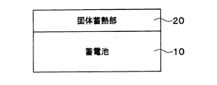
- FIG. 1 is a configuration diagram of a storage battery system according to a first embodiment of the present disclosure. It is a figure for demonstrating the inflow heat amount from the outside with respect to a storage battery system, It is a figure for demonstrating the temperature change of the storage battery by a fixed heat storage part, It is the figure which showed the temperature change of the storage battery in case the maximum temperature of a storage battery is 35 degreeC, and the volume of a solid heat storage part is 0.4L, It is the figure which showed the temperature change of the storage battery in case the maximum temperature of a storage battery is 35 degreeC, and the volume of a solid heat storage part is 1.5L, It is the figure which showed the temperature change of the storage battery in case the maximum temperature of a storage battery is 40 degreeC, and the volume of a solid heat storage part is 1.5L, It is the figure which showed the temperature change of the storage battery in case the maximum temperature of a storage battery is 40 degreeC, and the volume of a solid heat storage part is 1.5L, It is the figure which showed the temperature change of the storage
- the storage battery system is a drive source mounted on an electric vehicle such as a hybrid vehicle.
- the storage battery system is also used for a power source for driving a load such as a motor generator, a power source for an electronic device, and the like.
- the storage battery system includes a storage battery 10 and a solid heat storage unit 20.
- the storage battery 10 is a chargeable / dischargeable secondary battery.
- the storage battery 10 is mounted on a vehicle.
- the storage battery 10 includes a plurality of battery cells such as lithium ion batteries and a case that houses the plurality of battery cells.
- the outer shape of the case is a rectangular parallelepiped, for example.
- the case is made of a metal material, a resin material, or the like.
- a plurality of battery cells are connected in series to constitute one battery.
- the battery cell is a plate or block.
- the solid heat storage unit 20 plays a role of maintaining the temperature of the storage battery 10 constant when the temperature of the storage battery 10 reaches the phase transition temperature.
- the solid heat storage unit 20 is configured by a heat storage material that reversibly undergoes phase transition between a solid phase and a solid phase at a certain phase transition temperature with absorption and release of latent heat. That is, the solid heat storage unit 20 causes a solid phase-solid phase transition while maintaining a solid state.
- the solid heat storage unit 20 is configured in a plate shape.
- the solid heat storage unit 20 is in direct contact with the storage battery 10. According to this, since the latent heat can be directly exchanged between the solid heat storage unit 20 and the storage battery 10, the heat retention effect of the storage battery 10 by the solid heat storage unit 20 can be sufficiently obtained.
- the solid heat storage unit 20 is configured to have the same size as one side surface of the storage battery 10. That is, the solid heat storage unit 20 is in contact with the entire side surface of the storage battery 10.
- a method for bringing the solid heat storage unit 20 and the storage battery 10 into direct contact there are a method using grease, a method using a case for pressing the solid heat storage unit 20 and the storage battery 10 together, and the like.
- the heat storage material is configured to include vanadium.
- vanadium dioxide VO 2
- the phase transition temperature of the solid heat storage unit 20 is set to a desired temperature by adding an additive to vanadium dioxide.
- the phase transition temperature is set to 30 ° C., for example.
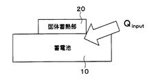
- the temperature of the storage battery 10 rises due to the inflow heat quantity (Q input ) from the outside such as the heat of the vehicle and solar heat.
- the solid heat storage unit 20 is drawn to a size smaller than one side surface of the storage battery 10 in order to illustrate the inflow heat amount.
- Equation 1 shows that the cumulative inflow heat quantity Q input up to a certain time is consumed by the temperature rise ⁇ T and the latent heat ⁇ H in the solid-phase state transition of the solid heat storage section 20. In other words, the temperature rise of the storage battery system is consumed by the latent heat ⁇ H, so that the temperature of the storage battery system is kept constant.
- the amount of heat flowing into the storage battery 10 is all used to increase the temperature of the storage battery system. . Therefore, the temperature of the storage battery 10 continues to rise.
- FIGS. 4 to 7 show the temperature change of the storage battery 10 with respect to time. 4 and 5 show a case where the maximum temperature of the storage battery 10 reaches 35 ° C., and FIGS. 6 and 7 show a case where the maximum temperature of the storage battery 10 reaches 40 ° C.
- the temperature of the storage battery 10 rises from about 6 o'clock, reaches the maximum temperature from 13:00 to 14:00, and falls after 14:00. And in the structure by which the storage battery 10 was equipped with the solid heat storage part 20, it turns out that the temperature rise of the storage battery 10 is suppressed after 8:00.
- the maximum temperature of the storage battery 10 is suppressed by adopting a configuration including not only the storage battery 10 but also the solid heat storage unit 20. Furthermore, since the amount of latent heat absorbed by the solid heat storage unit 20 from the storage battery 10 is increased by increasing the volume of the solid heat storage unit 20, the heat retention effect of the storage battery 10 is improved.
- the solid-state heat storage unit 20 that causes a solid-phase-solid phase transition is mounted on the storage battery 10.
- the container for maintaining the shape of the solid heat storage part 20 can be made unnecessary.
- the thermal resistance of outer walls, such as a container at the time of exchanging latent heat between the storage battery 10 and the solid heat storage part 20, can be reduced.
- the life of the storage battery 10 can be extended by mitigating changes in the temperature of the storage battery 10 without using a heat retaining device such as a heater or a cooling device.
- the temperature retaining device does not operate when the engine is stopped, so that it cannot cope with the temperature change of the storage battery 10.
- the solid heat storage unit 20 according to the present embodiment can obtain a high effect without using a heat retaining device even when the engine is stopped.
- the solid heat storage unit 20 surrounds the storage battery 10.
- the solid heat storage unit 20 is configured in a cylindrical shape and surrounds the entire four side surfaces of the case of the storage battery 10. That is, both end surfaces of the case of the storage battery 10 are exposed from the solid heat storage unit 20.
- the solid heat storage unit 20 can absorb latent heat from multiple directions of the storage battery 10, the heat retention effect of the storage battery 10 by the solid heat storage unit 20 can be sufficiently obtained.
- the storage battery system includes a storage battery 10, a solid heat storage unit 20, and a flow path unit 30.
- the flow path section 30 constitutes a flow path for heat exchange between the storage battery 10 and the solid heat storage section 20 through the heat medium by circulating the heat medium between the storage battery 10 and the solid heat storage section 20.
- the heat medium flows in the space between the storage battery 10 and the inner wall surface of the flow path portion 30.
- the storage battery 10 and the solid heat storage unit 20 are spaced apart.
- the heat medium is, for example, gas or water.
- the solid heat storage unit 20 is solid, there is a merit that it is easy to handle a liquid such as water.
- the storage battery 10 and the solid heat storage part 20 can be arrange
- the configuration of the storage battery system shown in each of the above embodiments is an example, and is not limited to the configuration shown above, and may be another configuration that can realize the present disclosure.
- the storage battery 10 is not limited to being mounted on a vehicle, and the storage battery 10 may be stationary.
- the external shape of the storage battery 10 is not limited to a rectangular parallelepiped as described above, and other external shapes may be adopted.
- the solid heat storage unit 20 is configured in a cylindrical shape that surrounds the storage battery 10, but may also surround the entire storage battery 10. A connector for taking out the power from the storage battery 10 is exposed from the solid heat storage unit 20.
Landscapes
- Engineering & Computer Science (AREA)
- Manufacturing & Machinery (AREA)
- Chemical & Material Sciences (AREA)
- Chemical Kinetics & Catalysis (AREA)
- Electrochemistry (AREA)
- General Chemical & Material Sciences (AREA)
- Secondary Cells (AREA)
- Battery Mounting, Suspending (AREA)
Abstract
蓄電池システムは充放電可能な蓄電池(10)および固体蓄熱部(20)を有する。固体蓄熱部は、ある相転移温度で固相と固相との間を潜熱の吸収、放出を伴って可逆的に相転移する蓄熱材によって構成される。蓄熱材は、前記蓄電池の温度が前記相転移温度に達した際に固相-固相間状態相転移を起こすことにより、前記蓄電池の温度を前記相転移温度に維持する。
Description
本出願は、2015年8月7日に出願された日本出願番号2015-157042号に基づくもので、ここにその記載内容を援用する。
本開示は、充放電可能な蓄電池を備えた蓄電池システムに関する。
潜熱蓄熱材が内包された被覆型粒子を含有する蓄熱シートが、例えば特許文献1で提案されている。この蓄熱シートは、潜熱蓄熱材が液相から固相、固相から液相に状態間相転移を起こす際に、熱を吸収したり放出したりする性質を利用することで対象物の温度を維持する。被覆型粒子は、液相に相変化した潜熱蓄熱材の形状を維持するためのカプセル状の容器の役割を果たしている。
しかしながら、上記従来の技術では、潜熱蓄熱材が固相から液相に相転移したときの潜熱蓄熱材の形状を維持するために容器が必要になるので、被覆型粒子における熱の出し入れ時に容器が熱抵抗になってしまう。
ここで、蓄電池は、充放電に応じた発熱や太陽熱による温度上昇等で電解液が劣化し、寿命が短縮することが知られている。このため、上述の蓄熱シートを用いて蓄電池の温度の上昇を抑制することが考えられる。しかし、熱抵抗による損失によって蓄熱シートの保温効果が充分に得られないと懸念される。
本開示は、蓄電池システムを提供することを目的とする。
本開示の第一の態様において、蓄電池システムは、充放電可能な蓄電池を備える。蓄電池システムは更に、ある相転移温度で固相と固相との間を潜熱の吸収、放出を伴って可逆的に相転移する蓄熱材によって構成されており、前記蓄電池の温度が前記相転移温度に達した際に固相-固相間状態相転移を起こすことにより、前記蓄電池の温度を前記相転移温度に維持する固体蓄熱部を備える。
これによると、固体蓄熱部が相転移を発生させても固体の状態が維持されるので、固体蓄熱部の形状を維持するための容器が不要になる。したがって、固体蓄熱部が蓄電池から潜熱を吸収する際の容器等の外壁の熱抵抗を低減することができる。
本開示についての上記目的およびその他の目的、特徴や利点は、添付の図面を参照しながら下記の詳細な記述により、より明確になる。その図面は、
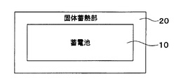
図1は、本開示の第1実施形態に係る蓄電池システムの構成図であり、
蓄電池システムに対する外部からの流入熱量を説明するための図であり、
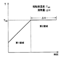
固定蓄熱部による蓄電池の温度変化を説明するための図であり、
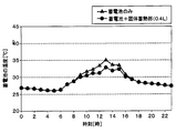
蓄電池の最高温度が35℃、固体蓄熱部の体積が0.4Lの場合の蓄電池の温度変化を示した図であり、
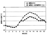
蓄電池の最高温度が35℃、固体蓄熱部の体積が1.5Lの場合の蓄電池の温度変化を示した図であり、
蓄電池の最高温度が40℃、固体蓄熱部の体積が1.5Lの場合の蓄電池の温度変化を示した図であり、
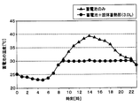
蓄電池の最高温度が40℃、固体蓄熱部の体積が3.0Lの場合の蓄電池の温度変化を示した図であり、
本開示の第2実施形態に係る蓄電池システムの構成図であり、また
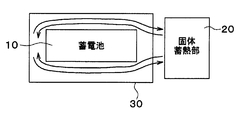
本開示の第3実施形態に係る蓄電池システムの構成図である。
以下、本開示の実施形態について図に基づいて説明する。
(第1実施形態)
以下、本開示の第1実施形態について図を参照して説明する。本実施形態に係る蓄電池システムは、例えばハイブリッド車等の電気自動車に搭載される駆動源である。また、蓄電池システムは、モータジェネレータ等の負荷を駆動するための電源や電子機器の電源等にも用いられる。
以下、本開示の第1実施形態について図を参照して説明する。本実施形態に係る蓄電池システムは、例えばハイブリッド車等の電気自動車に搭載される駆動源である。また、蓄電池システムは、モータジェネレータ等の負荷を駆動するための電源や電子機器の電源等にも用いられる。
図1に示されるように、蓄電池システムは、蓄電池10及び固体蓄熱部20を備えて構成されている。蓄電池10は、充放電可能な二次電池である。蓄電池10は、車両に搭載される。
具体的には、蓄電池10は、リチウムイオン電池等の複数の電池セルと、複数の電池セルを収容するケースと、を有している。ケースの外形は例えば直方体である。ケースは金属材料や樹脂材料等により構成されている。複数の電池セルは直列に接続されることで1つの電池を構成している。電池セルは、板状やブロック状等のものが採用される。
固体蓄熱部20は、蓄電池10の温度が相転移温度に達した際に、蓄電池10の温度を一定に維持する役割を果たす。固体蓄熱部20は、ある相転移温度で固相と固相との間を潜熱の吸収、放出を伴って可逆的に相転移する蓄熱材によって構成されている。つまり、固体蓄熱部20は、固体の状態を維持しつつ、固相-固相間状態相転移を起こす。
固体蓄熱部20は、板状に構成されている。また、固体蓄熱部20は、蓄電池10に直接接している。これによると、固体蓄熱部20と蓄電池10とで直接潜熱のやりとりができるので、固体蓄熱部20による蓄電池10の保温効果を充分に得ることができる。
なお、本実施形態では、固体蓄熱部20は蓄電池10の一側面と同じサイズに構成されている。すなわち、固体蓄熱部20は蓄電池10の一側面の全体に接触している。固体蓄熱部20と蓄電池10とを直接接触させる方法として、グリースを用いる方法や、固体蓄熱部20と蓄電池10とを互いに押し付けるケースを用いる方法等がある。
蓄熱材は、バナジウムを含んで構成されている。例えば、蓄熱材として二酸化バナジウム(VO2)が採用される。固体蓄熱部20の相転移温度は、二酸化バナジウムに添加物が加えられることで所望の温度に設定されている。相転移温度は例えば30℃に設定されている。
次に、蓄電池10及び固体蓄熱部20の熱平衡モデルについて説明する。図2に示されるように、蓄電池10は、車両の熱や太陽熱等の外部からの流入熱量(Qinput)によって温度が上昇する。なお、図2では、流入熱量を図示するために固体蓄熱部20を蓄電池10の一側面よりも小さいサイズに描いている。
ここで、蓄電池システムの全体熱容量をC、蓄電池システムの全体重量をm、蓄電池システムの温度上昇をΔT、固体蓄熱部20の重量をmVO2、潜熱量をΔHとすると、蓄電池システムの熱平衡モデルは以下の数1で表される。
(数1)
∫Qinputdt=Cm(ΔT)+ΔH
また、1kg当たりの潜熱量をΔhとすると、潜熱量ΔHは以下の数2で表される。
(数2)
ΔH=mVO2(Δh)
数1は、ある時間までの積算の流入熱量Qinputは温度上昇ΔTと固体蓄熱部20の固相-固相間状態相転移における潜熱ΔHで消費されることを示している。言い換えると、蓄電池システムの温度上昇ΔTが潜熱ΔHによって消費されることで蓄電池システムの温度が一定に保たれる。
(数1)
∫Qinputdt=Cm(ΔT)+ΔH
また、1kg当たりの潜熱量をΔhとすると、潜熱量ΔHは以下の数2で表される。
(数2)
ΔH=mVO2(Δh)
数1は、ある時間までの積算の流入熱量Qinputは温度上昇ΔTと固体蓄熱部20の固相-固相間状態相転移における潜熱ΔHで消費されることを示している。言い換えると、蓄電池システムの温度上昇ΔTが潜熱ΔHによって消費されることで蓄電池システムの温度が一定に保たれる。
具体的には、図3に示されるように、蓄電池システムの温度が相転移温度(TMI)に達する前の第1領域では、蓄電池10への流入熱量は全て蓄電池システムの温度上昇に使われる。したがって、蓄電池10の温度は上昇し続ける。
この後の第2領域では、蓄電池10の温度が相転移温度に達した際に蓄電池10と固体蓄熱部20との間で潜熱に基づく固相-固相間状態相転移を起こす。すなわち、固体蓄熱部20は、蓄電池10から潜熱を吸収する。これにより、ΔH=∫Qinputdtに達するまで蓄電池10の温度は相転移温度を維持する。
発明者らは、蓄電池10のみの場合と固体蓄熱部20を搭載した場合との蓄電池10の温度変化を調べた。その結果を図4~図7に示す。図4~図7は、時刻に対する蓄電池10の温度変化を示している。また、図4及び図5は蓄電池10の最高温度が35℃に達する場合を示し、図6及び図7は蓄電池10の最高温度が40℃に達する場合を示している。
まず、蓄電池10のみの場合、蓄電池10の温度は6時頃から上昇し、13時~14時頃に最高温度に達し、14時以降は下降していく。そして、蓄電池10に固体蓄熱部20が備えられた構成では、8時以降から蓄電池10の温度上昇が抑制されていることがわかる。
具体的には、図4に示されるように、固体蓄熱部20が0.4Lの場合、蓄電池10の温度は相転移温度を超えるが、蓄電池10のみの場合よりも温度が抑えられた。一方、図5に示されるように、固体蓄熱部20が1.5Lの場合、蓄電池10の温度は相転移温度を超えずに相転移温度に維持された。
同様に、図6に示されるように、固体蓄熱部20が1.5Lの場合、蓄電池10の温度は相転移温度を超えるが、蓄電池10のみの場合よりも温度が抑えられた。一方、図7に示されるように、固体蓄熱部20が3.0Lの場合、蓄電池10の温度は相転移温度を超えずに相転移温度に維持された。
このように、蓄電池10のみではなく固体蓄熱部20を備えた構成とすることで、蓄電池10の最高温度が抑制される。さらに、固体蓄熱部20の体積を増やすことで固体蓄熱部20が蓄電池10から吸収する潜熱量が増えるので、蓄電池10の保温効果が向上する。
以上説明したように、本実施形態では、固相-固相間状態相転移を起こす固体蓄熱部20を蓄電池10に搭載した構成となっている。これにより、固体蓄熱部20は固体の状態を維持した状態で相転移を起こすので、固体蓄熱部20の形状を維持するための容器を不要にすることができる。このため、蓄電池10と固体蓄熱部20との間で潜熱をやりとりする際の容器等の外壁の熱抵抗を低減することができる。
特に、蓄電池10の充放電に応じた発熱や、太陽熱による夏季の温度上昇等により、蓄電池10内で電解液が劣化して寿命が短縮することを抑制することができる。言い換えると、ヒーターや冷却装置等の保温装置を用いずに蓄電池10の温度の変化を緩和させることで、蓄電池10の寿命を長くすることができる。
また、ハイブリッド車等のように独立の蓄電池10が搭載された車両では、エンジン停車時に保温装置が稼働しないために蓄電池10の温度変化に対応できない。しかし、本実施形態に係る固体蓄熱部20は、エンジン停車時でも保温装置を用いずに高い効果を得ることができる。
(第2実施形態)
本実施形態では、第1実施形態と異なる部分について説明する。図8に示されるように、固体蓄熱部20は、蓄電池10を囲んでいる。具体的には、固体蓄熱部20は、筒状に構成されていると共に、蓄電池10のケースの4側面全体を囲んでいる。つまり、蓄電池10のケースの両端面は固体蓄熱部20から露出している。
本実施形態では、第1実施形態と異なる部分について説明する。図8に示されるように、固体蓄熱部20は、蓄電池10を囲んでいる。具体的には、固体蓄熱部20は、筒状に構成されていると共に、蓄電池10のケースの4側面全体を囲んでいる。つまり、蓄電池10のケースの両端面は固体蓄熱部20から露出している。
これによると、固体蓄熱部20が蓄電池10の多方向から潜熱を吸収できるので、固体蓄熱部20による蓄電池10の保温効果を充分に得ることができる。
(第3実施形態)
本実施形態では、第1、第2実施形態と異なる部分について説明する。図9に示されるように、蓄電池システムは、蓄電池10、固体蓄熱部20、及び流路部30を備えて構成されている。
本実施形態では、第1、第2実施形態と異なる部分について説明する。図9に示されるように、蓄電池システムは、蓄電池10、固体蓄熱部20、及び流路部30を備えて構成されている。
流路部30は、蓄電池10と固体蓄熱部20との間に熱媒体を循環させることで熱媒体を介して蓄電池10と固体蓄熱部20とを熱交換させる流路を構成する。そして、蓄電池10と流路部30の内壁面との間の空間に熱媒体が流れるようになっている。
すなわち、本実施形態では、蓄電池10と固体蓄熱部20とは離間して配置されている。熱媒体は例えばガスや水である。上述のように、固体蓄熱部20は固体であるので、水のような液体に対して取扱いが容易であるというメリットがある。また、蓄電池10と固体蓄熱部20とを別々に配置できるので、車両のスペースを有効活用できるというメリットがある。
(他の実施形態)
上記各実施形態で示された蓄電池システムの構成は一例であり、上記で示した構成に限定されることなく、本開示を実現できる他の構成とすることもできる。例えば、蓄電池10は車両に搭載される場合に限られず、蓄電池10は定置用のものでも良い。もちろん、蓄電池10の外形は上述のように直方体に限られず、他の外形が採用されることもある。
上記各実施形態で示された蓄電池システムの構成は一例であり、上記で示した構成に限定されることなく、本開示を実現できる他の構成とすることもできる。例えば、蓄電池10は車両に搭載される場合に限られず、蓄電池10は定置用のものでも良い。もちろん、蓄電池10の外形は上述のように直方体に限られず、他の外形が採用されることもある。
第2実施形態では、固体蓄熱部20は蓄電池10を囲む筒状に構成されていたが、蓄電池10の全体を囲んでいても良い。なお、蓄電池10から電源を取り出すためのコネクタ等は固体蓄熱部20から露出される。
本開示は、実施例に準拠して記述されたが、本開示は当該実施例や構造に限定されるものではないと理解される。本開示は、様々な変形例や均等範囲内の変形をも包含する。加えて、様々な組み合わせや形態、さらには、それらに一要素のみ、それ以上、あるいはそれ以下、を含む他の組み合わせや形態をも、本開示の範疇や思想範囲に入る。
Claims (6)
- 充放電可能な蓄電池(10)と、
ある相転移温度で固相と固相との間を潜熱の吸収、放出を伴って可逆的に相転移する蓄熱材によって構成されており、前記蓄電池(10)の温度が前記相転移温度に達した際に固相-固相間状態相転移を起こすことにより、前記蓄電池(10)の温度を前記相転移温度に維持する固体蓄熱部(20)と、
を備えている蓄電池システム。 - 前記固体蓄熱部(20)は、前記蓄電池(10)に直接接している、請求項1に記載の蓄電池システム。
- 前記固体蓄熱部(20)は、前記蓄電池(10)を囲んでいる、請求項1または2に記載の蓄電池システム。
- 前記蓄電池(10)と前記固体蓄熱部(20)との間に熱媒体を循環させることで前記熱媒体を介して前記蓄電池(10)と前記固体蓄熱部(20)とを熱交換させるための流路部(30)を備えている、請求項1に記載の蓄電池システム。
- 蓄熱材は、バナジウムを含んで構成されている、請求項1ないし4のいずれか1つに記載の蓄電池システム。
- 前記蓄電池(10)は、車両に搭載される、請求項1ないし5のいずれか1つに記載の蓄電池システム。
Priority Applications (1)
| Application Number | Priority Date | Filing Date | Title |
|---|---|---|---|
| US15/744,128 US20180212290A1 (en) | 2015-08-07 | 2016-06-08 | Storage battery system |
Applications Claiming Priority (2)
| Application Number | Priority Date | Filing Date | Title |
|---|---|---|---|
| JP2015157042A JP2017037743A (ja) | 2015-08-07 | 2015-08-07 | 蓄電池システム |
| JP2015-157042 | 2015-08-07 |
Publications (1)
| Publication Number | Publication Date |
|---|---|
| WO2017026084A1 true WO2017026084A1 (ja) | 2017-02-16 |
Family
ID=57984166
Family Applications (1)
| Application Number | Title | Priority Date | Filing Date |
|---|---|---|---|
| PCT/JP2016/002775 Ceased WO2017026084A1 (ja) | 2015-08-07 | 2016-06-08 | 蓄電池システム |
Country Status (3)
| Country | Link |
|---|---|
| US (1) | US20180212290A1 (ja) |
| JP (1) | JP2017037743A (ja) |
| WO (1) | WO2017026084A1 (ja) |
Families Citing this family (6)
| Publication number | Priority date | Publication date | Assignee | Title |
|---|---|---|---|---|
| CN108141520A (zh) * | 2015-10-27 | 2018-06-08 | 索尼公司 | 电子设备 |
| JPWO2018135140A1 (ja) * | 2017-01-19 | 2019-11-07 | ソニー株式会社 | 複合材料、電子機器および電子機器の製造方法 |
| JP2020145060A (ja) * | 2019-03-06 | 2020-09-10 | 株式会社日立製作所 | 電池システム及び電池パック |
| JP7218868B2 (ja) * | 2019-06-11 | 2023-02-07 | 株式会社アイシン | 蓄熱放熱システム |
| CN112537385B (zh) * | 2020-12-30 | 2023-03-21 | 山东济燃氢动力有限公司 | 一种氢燃料电池摩托车 |
| CN114865196B (zh) * | 2022-06-10 | 2024-07-19 | 贵州电网有限责任公司 | 一种寒区自控温光伏系统电池箱及控温方法 |
Citations (3)
| Publication number | Priority date | Publication date | Assignee | Title |
|---|---|---|---|---|
| JP2008305575A (ja) * | 2007-06-05 | 2008-12-18 | Denso Corp | 電池温度調節装置 |
| JP2009140786A (ja) * | 2007-12-07 | 2009-06-25 | Sekisui Chem Co Ltd | 車載用組電池 |
| JP2015029036A (ja) * | 2013-06-27 | 2015-02-12 | ソニー株式会社 | 電子機器および電子機器の制御方法 |
Family Cites Families (4)
| Publication number | Priority date | Publication date | Assignee | Title |
|---|---|---|---|---|
| EP2522047A1 (en) * | 2010-01-08 | 2012-11-14 | Dow Global Technologies LLC | Thermal management of an electrochemical cell by a combination of heat transfer fluid and phase change material |
| JP5743348B2 (ja) * | 2010-04-15 | 2015-07-01 | エルジー・ケム・リミテッド | バッテリモジュール |
| DE102011002549A1 (de) * | 2011-01-12 | 2012-07-12 | Robert Bosch Gmbh | Batterietemperierung durch Aggregatzustandswechselmaterial |
| WO2014139901A1 (en) * | 2013-03-12 | 2014-09-18 | Akzo Nobel Chemicals International B.V. | Sunscreen formulations |
-
2015
- 2015-08-07 JP JP2015157042A patent/JP2017037743A/ja active Pending
-
2016
- 2016-06-08 WO PCT/JP2016/002775 patent/WO2017026084A1/ja not_active Ceased
- 2016-06-08 US US15/744,128 patent/US20180212290A1/en not_active Abandoned
Patent Citations (3)
| Publication number | Priority date | Publication date | Assignee | Title |
|---|---|---|---|---|
| JP2008305575A (ja) * | 2007-06-05 | 2008-12-18 | Denso Corp | 電池温度調節装置 |
| JP2009140786A (ja) * | 2007-12-07 | 2009-06-25 | Sekisui Chem Co Ltd | 車載用組電池 |
| JP2015029036A (ja) * | 2013-06-27 | 2015-02-12 | ソニー株式会社 | 電子機器および電子機器の制御方法 |
Also Published As
| Publication number | Publication date |
|---|---|
| JP2017037743A (ja) | 2017-02-16 |
| US20180212290A1 (en) | 2018-07-26 |
Similar Documents
| Publication | Publication Date | Title |
|---|---|---|
| WO2017026084A1 (ja) | 蓄電池システム | |
| Al‐Zareer et al. | A review of novel thermal management systems for batteries | |
| JP6719562B2 (ja) | バッテリーモジュール | |
| Liu et al. | Recent developments of thermal management strategies for lithium‐ion batteries: a state‐of‐the‐art review | |
| Lin et al. | Experiment and simulation of a LiFePO4 battery pack with a passive thermal management system using composite phase change material and graphite sheets | |
| Yamada et al. | Analysis of a lithium-ion battery cooling system for electric vehicles using a phase-change material and heat pipes | |
| Somasundaram et al. | Thermal–electrochemical model for passive thermal management of a spiral-wound lithium-ion battery | |
| CN109923731B (zh) | 设置有pcm单元的电池冷却热沉 | |
| JP6567553B2 (ja) | 電池パック | |
| Lin et al. | Research progress of phase change storage material on power battery thermal management | |
| CN102201603B (zh) | 用于机动车辆的储能器 | |
| EP3361554A1 (en) | Battery module, battery pack comprising battery module, and vehicle comprising battery pack | |
| KR102023921B1 (ko) | 배터리 모듈 | |
| JP2013178966A (ja) | 電池モジュール | |
| Sikarwar et al. | Battery thermal management system for the cooling of Li-Ion batteries, used in electric vehicles | |
| CN107112609A (zh) | 电池及使用该电池的移动平台 | |
| JP2012048905A (ja) | 冷却材を備える電池、並びに冷却材を備える組電池 | |
| KR101960922B1 (ko) | 배터리 모듈 | |
| CN205810969U (zh) | 动力电池及使用该动力电池的无人飞行器 | |
| US20210083342A1 (en) | Battery Module with Enhanced Cooling Efficiency, and Battery Pack Comprising Same | |
| JPWO2013141242A1 (ja) | イオン液体を用いたリチウムイオン二次電池及びリチウムイオン二次電池モジュール並びにこれらの保温装置 | |
| JP2020140929A (ja) | 電池パック | |
| JP2020064755A (ja) | 電池パック | |
| JP6289237B2 (ja) | 組電池 | |
| TW201836237A (zh) | 充電裝置 |
Legal Events
| Date | Code | Title | Description |
|---|---|---|---|
| 121 | Ep: the epo has been informed by wipo that ep was designated in this application |
Ref document number: 16834788 Country of ref document: EP Kind code of ref document: A1 |
|
| WWE | Wipo information: entry into national phase |
Ref document number: 15744128 Country of ref document: US |
|
| NENP | Non-entry into the national phase |
Ref country code: DE |
|
| 122 | Ep: pct application non-entry in european phase |
Ref document number: 16834788 Country of ref document: EP Kind code of ref document: A1 |