WO2017018535A1 - Glass plate module - Google Patents
Glass plate module Download PDFInfo
- Publication number
- WO2017018535A1 WO2017018535A1 PCT/JP2016/072427 JP2016072427W WO2017018535A1 WO 2017018535 A1 WO2017018535 A1 WO 2017018535A1 JP 2016072427 W JP2016072427 W JP 2016072427W WO 2017018535 A1 WO2017018535 A1 WO 2017018535A1
- Authority
- WO
- WIPO (PCT)
- Prior art keywords
- adhesive
- glass plate
- mask layer
- vehicle
- laminated
- Prior art date
Links
Images


Classifications
-
- B—PERFORMING OPERATIONS; TRANSPORTING
- B32—LAYERED PRODUCTS
- B32B—LAYERED PRODUCTS, i.e. PRODUCTS BUILT-UP OF STRATA OF FLAT OR NON-FLAT, e.g. CELLULAR OR HONEYCOMB, FORM
- B32B3/00—Layered products comprising a layer with external or internal discontinuities or unevennesses, or a layer of non-planar form; Layered products having particular features of form
- B32B3/26—Layered products comprising a layer with external or internal discontinuities or unevennesses, or a layer of non-planar form; Layered products having particular features of form characterised by a particular shape of the outline of the cross-section of a continuous layer; characterised by a layer with cavities or internal voids ; characterised by an apertured layer
- B32B3/266—Layered products comprising a layer with external or internal discontinuities or unevennesses, or a layer of non-planar form; Layered products having particular features of form characterised by a particular shape of the outline of the cross-section of a continuous layer; characterised by a layer with cavities or internal voids ; characterised by an apertured layer characterised by an apertured layer, the apertures going through the whole thickness of the layer, e.g. expanded metal, perforated layer, slit layer regular cells B32B3/12
-
- B—PERFORMING OPERATIONS; TRANSPORTING
- B32—LAYERED PRODUCTS
- B32B—LAYERED PRODUCTS, i.e. PRODUCTS BUILT-UP OF STRATA OF FLAT OR NON-FLAT, e.g. CELLULAR OR HONEYCOMB, FORM
- B32B17/00—Layered products essentially comprising sheet glass, or glass, slag, or like fibres
- B32B17/06—Layered products essentially comprising sheet glass, or glass, slag, or like fibres comprising glass as the main or only constituent of a layer, next to another layer of a specific material
- B32B17/10—Layered products essentially comprising sheet glass, or glass, slag, or like fibres comprising glass as the main or only constituent of a layer, next to another layer of a specific material of synthetic resin
- B32B17/10005—Layered products essentially comprising sheet glass, or glass, slag, or like fibres comprising glass as the main or only constituent of a layer, next to another layer of a specific material of synthetic resin laminated safety glass or glazing
- B32B17/10009—Layered products essentially comprising sheet glass, or glass, slag, or like fibres comprising glass as the main or only constituent of a layer, next to another layer of a specific material of synthetic resin laminated safety glass or glazing characterized by the number, the constitution or treatment of glass sheets
- B32B17/10036—Layered products essentially comprising sheet glass, or glass, slag, or like fibres comprising glass as the main or only constituent of a layer, next to another layer of a specific material of synthetic resin laminated safety glass or glazing characterized by the number, the constitution or treatment of glass sheets comprising two outer glass sheets
-
- B—PERFORMING OPERATIONS; TRANSPORTING
- B32—LAYERED PRODUCTS
- B32B—LAYERED PRODUCTS, i.e. PRODUCTS BUILT-UP OF STRATA OF FLAT OR NON-FLAT, e.g. CELLULAR OR HONEYCOMB, FORM
- B32B17/00—Layered products essentially comprising sheet glass, or glass, slag, or like fibres
- B32B17/06—Layered products essentially comprising sheet glass, or glass, slag, or like fibres comprising glass as the main or only constituent of a layer, next to another layer of a specific material
- B32B17/10—Layered products essentially comprising sheet glass, or glass, slag, or like fibres comprising glass as the main or only constituent of a layer, next to another layer of a specific material of synthetic resin
- B32B17/10005—Layered products essentially comprising sheet glass, or glass, slag, or like fibres comprising glass as the main or only constituent of a layer, next to another layer of a specific material of synthetic resin laminated safety glass or glazing
- B32B17/10009—Layered products essentially comprising sheet glass, or glass, slag, or like fibres comprising glass as the main or only constituent of a layer, next to another layer of a specific material of synthetic resin laminated safety glass or glazing characterized by the number, the constitution or treatment of glass sheets
- B32B17/10064—Layered products essentially comprising sheet glass, or glass, slag, or like fibres comprising glass as the main or only constituent of a layer, next to another layer of a specific material of synthetic resin laminated safety glass or glazing characterized by the number, the constitution or treatment of glass sheets comprising at least two glass sheets, only one of which being an outer layer
-
- B—PERFORMING OPERATIONS; TRANSPORTING
- B32—LAYERED PRODUCTS
- B32B—LAYERED PRODUCTS, i.e. PRODUCTS BUILT-UP OF STRATA OF FLAT OR NON-FLAT, e.g. CELLULAR OR HONEYCOMB, FORM
- B32B17/00—Layered products essentially comprising sheet glass, or glass, slag, or like fibres
- B32B17/06—Layered products essentially comprising sheet glass, or glass, slag, or like fibres comprising glass as the main or only constituent of a layer, next to another layer of a specific material
- B32B17/10—Layered products essentially comprising sheet glass, or glass, slag, or like fibres comprising glass as the main or only constituent of a layer, next to another layer of a specific material of synthetic resin
- B32B17/10005—Layered products essentially comprising sheet glass, or glass, slag, or like fibres comprising glass as the main or only constituent of a layer, next to another layer of a specific material of synthetic resin laminated safety glass or glazing
- B32B17/10165—Functional features of the laminated safety glass or glazing
- B32B17/10339—Specific parts of the laminated safety glass or glazing being colored or tinted
- B32B17/10348—Specific parts of the laminated safety glass or glazing being colored or tinted comprising an obscuration band
-
- B—PERFORMING OPERATIONS; TRANSPORTING
- B32—LAYERED PRODUCTS
- B32B—LAYERED PRODUCTS, i.e. PRODUCTS BUILT-UP OF STRATA OF FLAT OR NON-FLAT, e.g. CELLULAR OR HONEYCOMB, FORM
- B32B17/00—Layered products essentially comprising sheet glass, or glass, slag, or like fibres
- B32B17/06—Layered products essentially comprising sheet glass, or glass, slag, or like fibres comprising glass as the main or only constituent of a layer, next to another layer of a specific material
- B32B17/10—Layered products essentially comprising sheet glass, or glass, slag, or like fibres comprising glass as the main or only constituent of a layer, next to another layer of a specific material of synthetic resin
- B32B17/10005—Layered products essentially comprising sheet glass, or glass, slag, or like fibres comprising glass as the main or only constituent of a layer, next to another layer of a specific material of synthetic resin laminated safety glass or glazing
- B32B17/10165—Functional features of the laminated safety glass or glazing
- B32B17/10339—Specific parts of the laminated safety glass or glazing being colored or tinted
- B32B17/10357—Specific parts of the laminated safety glass or glazing being colored or tinted comprising a tinted intermediate film
-
- B—PERFORMING OPERATIONS; TRANSPORTING
- B32—LAYERED PRODUCTS
- B32B—LAYERED PRODUCTS, i.e. PRODUCTS BUILT-UP OF STRATA OF FLAT OR NON-FLAT, e.g. CELLULAR OR HONEYCOMB, FORM
- B32B7/00—Layered products characterised by the relation between layers; Layered products characterised by the relative orientation of features between layers, or by the relative values of a measurable parameter between layers, i.e. products comprising layers having different physical, chemical or physicochemical properties; Layered products characterised by the interconnection of layers
- B32B7/04—Interconnection of layers
- B32B7/12—Interconnection of layers using interposed adhesives or interposed materials with bonding properties
-
- B—PERFORMING OPERATIONS; TRANSPORTING
- B60—VEHICLES IN GENERAL
- B60J—WINDOWS, WINDSCREENS, NON-FIXED ROOFS, DOORS, OR SIMILAR DEVICES FOR VEHICLES; REMOVABLE EXTERNAL PROTECTIVE COVERINGS SPECIALLY ADAPTED FOR VEHICLES
- B60J1/00—Windows; Windscreens; Accessories therefor
-
- B—PERFORMING OPERATIONS; TRANSPORTING
- B60—VEHICLES IN GENERAL
- B60R—VEHICLES, VEHICLE FITTINGS, OR VEHICLE PARTS, NOT OTHERWISE PROVIDED FOR
- B60R11/00—Arrangements for holding or mounting articles, not otherwise provided for
- B60R11/02—Arrangements for holding or mounting articles, not otherwise provided for for radio sets, television sets, telephones, or the like; Arrangement of controls thereof
-
- B—PERFORMING OPERATIONS; TRANSPORTING
- B60—VEHICLES IN GENERAL
- B60R—VEHICLES, VEHICLE FITTINGS, OR VEHICLE PARTS, NOT OTHERWISE PROVIDED FOR
- B60R11/00—Arrangements for holding or mounting articles, not otherwise provided for
- B60R11/04—Mounting of cameras operative during drive; Arrangement of controls thereof relative to the vehicle
-
- B—PERFORMING OPERATIONS; TRANSPORTING
- B32—LAYERED PRODUCTS
- B32B—LAYERED PRODUCTS, i.e. PRODUCTS BUILT-UP OF STRATA OF FLAT OR NON-FLAT, e.g. CELLULAR OR HONEYCOMB, FORM
- B32B2250/00—Layers arrangement
- B32B2250/03—3 layers
-
- B—PERFORMING OPERATIONS; TRANSPORTING
- B32—LAYERED PRODUCTS
- B32B—LAYERED PRODUCTS, i.e. PRODUCTS BUILT-UP OF STRATA OF FLAT OR NON-FLAT, e.g. CELLULAR OR HONEYCOMB, FORM
- B32B2250/00—Layers arrangement
- B32B2250/05—5 or more layers
-
- B—PERFORMING OPERATIONS; TRANSPORTING
- B32—LAYERED PRODUCTS
- B32B—LAYERED PRODUCTS, i.e. PRODUCTS BUILT-UP OF STRATA OF FLAT OR NON-FLAT, e.g. CELLULAR OR HONEYCOMB, FORM
- B32B2250/00—Layers arrangement
- B32B2250/40—Symmetrical or sandwich layers, e.g. ABA, ABCBA, ABCCBA
-
- B—PERFORMING OPERATIONS; TRANSPORTING
- B32—LAYERED PRODUCTS
- B32B—LAYERED PRODUCTS, i.e. PRODUCTS BUILT-UP OF STRATA OF FLAT OR NON-FLAT, e.g. CELLULAR OR HONEYCOMB, FORM
- B32B2307/00—Properties of the layers or laminate
- B32B2307/40—Properties of the layers or laminate having particular optical properties
- B32B2307/402—Coloured
-
- B—PERFORMING OPERATIONS; TRANSPORTING
- B32—LAYERED PRODUCTS
- B32B—LAYERED PRODUCTS, i.e. PRODUCTS BUILT-UP OF STRATA OF FLAT OR NON-FLAT, e.g. CELLULAR OR HONEYCOMB, FORM
- B32B2605/00—Vehicles
- B32B2605/006—Transparent parts other than made from inorganic glass, e.g. polycarbonate glazings
Definitions
- the present invention relates to a glass plate module.
- a safety system has been proposed in which the brake operates.
- Such a system measures the distance to the vehicle ahead by using a laser radar or a camera.
- An information acquisition device such as a laser radar or a camera is generally disposed inside a windshield and performs measurement by irradiating infrared rays forward.
- a mask layer coated with dark ceramic is formed on the inner surface of the glass plate, and the information acquisition device is disposed thereon. Yes.
- a mask layer is generally formed near the periphery and upper center of the glass plate.
- an opening is formed in the mask layer, and laser light irradiated and received by the laser radar, infrared light received by the camera, and the like are irradiated or received through the opening.
- an information acquisition device is generally not fixed directly to the mask layer, but is fixed to the mask layer via an attachment member such as a bracket. That is, after fixing the attachment member to the mask layer with an adhesive or a double-sided tape, the information acquisition device is attached to the attachment member. And an information acquisition apparatus is arrange
- the double-sided tape has a function as a temporary fixing until the adhesive is solidified, and the adhesive has a function as a permanent fixing, so both are essential. It has become.
- the adhesive is not applied, the attachment member is fixed by the double-sided tape, so it may not be apparent at all that the adhesive is not applied.
- the adhesive layer and the double-sided tape cannot be visually recognized from being blocked by the mask layer from the outside of the vehicle. Therefore, the presence or absence of the adhesive cannot be confirmed after the mounting member is fixed to the mask layer. If the adhesive is not applied, the adhesive force of the double-sided tape alone is low, and the attachment member may be detached from the mask layer.
- the present invention has been made to solve the above problems, and an object of the present invention is to provide a glass plate module that can confirm the presence or absence of an adhesive even after the mounting member is mounted on the mask layer. .
- a glass plate module mounted on a vehicle according to the present invention includes a laminated glass in which an outer glass plate, an intermediate film, and an inner glass plate are laminated in this order, and a mask that is provided on the laminated glass and shields a visual field from the outside.
- a mounting member that supports an information acquisition device that acquires information from outside the vehicle, and is attached to a portion corresponding to the mask layer in the inner glass plate by at least first and second adhesive means
- the first adhesive means includes at least one adhesive
- the second adhesive means is configured to temporarily fix the adhesive before curing
- the attachment member faces the mask layer
- a fixing portion having an adhesive surface on which an adhesive means is provided, wherein the fixing portion includes at least one adhesive confirmation portion that allows the adhesive applied to the adhesive surface to be visually recognized from the inside of the vehicle. It is.
- the second bonding means may be at least one double-sided tape having a thickness of 0.2 mm or more and 0.8 mm or less.
- the adhesive confirmation part can be configured by a through-hole formed in the fixing part, and at least a part of the application area and the spread area of the adhesive are on the adhesive surface, It can comprise so that it may cross
- the adhesive may be applied linearly so as to intersect with the through hole, and the outer shape of the through hole has a length in a first direction in which the adhesive extends, and the first direction. It can be formed to be shorter than the length in the second direction orthogonal to each other.
- the “spreading area” is an area where the adhesive applied to the adhesive surface is sandwiched between the fixing portion and the mask layer and occupies the adhesive surface when it is spread, but it protrudes from the adhesive surface. This part is also included in the spread area.
- the adhesive confirmation part can be constituted by a notch formed in an edge part of the fixing part, and at least a part of the application area and the spread area of the adhesive, The adhesive surface can be configured to overlap the notch.
- the adhesive can be applied linearly so as to pass through the vicinity of the position farthest from the outer edge of the fixed portion.
- the shape of the notch is not particularly limited, but can be formed in an arc shape, for example.
- the adhesive may be constituted by a main body part and an extending part extending from the main body part to an edge part of the fixing part or the vicinity thereof when applied to the adhesion surface.
- the location where the extended part reaches the edge of the fixed part can constitute the adhesive confirmation part.
- the main body portion can be formed to extend in one direction, and the length of the extending portion in the extending direction of the main body portion can be shorter than the length of the main body portion.
- the mask layer can be formed of a dark ceramic film.
- a manufacturing method of a window module provided with an information acquisition device that is attached to a vehicle and acquires information from outside the vehicle, A laminated glass in which an outer glass plate, an intermediate film, and an inner glass plate are laminated in this order; A mask layer that is provided on the laminated glass and shields a visual field from the outside; An attachment member attached to the portion corresponding to the mask layer in the inner glass plate by at least first and second adhesive means and supporting the information acquisition device; A step of preparing a glass plate module comprising: a step of installing the information acquisition device on the inner glass plate side via the mounting member; Comprising The first adhesive means comprises at least one adhesive; The second bonding means is configured such that the adhesive performs temporary fixing before curing, The mounting member includes a fixing portion having an adhesive surface facing the mask layer and provided with the both adhesive means, The fixing portion has at least one adhesive confirmation portion that allows the adhesive applied to the adhesive surface to be visually recognized from the inside of the vehicle.
- a vehicle manufacturing method including an information acquisition device that acquires information from outside the vehicle.
- a laminated glass in which an outer glass plate, an intermediate film, and an inner glass plate are laminated in this order;
- a mask layer that is provided on the laminated glass and shields a visual field from the outside;
- An attachment member attached to the portion corresponding to the mask layer in the inner glass plate by at least first and second adhesive means and supporting the information acquisition device;
- a first step of fixing a glass plate module comprising: After the first step, a second step of installing the information acquisition device on the glass plate module;
- Comprising The first adhesive means comprises at least one adhesive;
- the second bonding means is configured such that the adhesive performs temporary fixing before curing,
- the mounting member includes a fixing portion having an adhesive surface facing the mask layer and provided with the both adhesive means,
- the fixing portion has at least one adhesive confirmation portion that allows the adhesive applied to the adhesive surface to be visually recognized from the inside of the vehicle.
- the presence or absence of the adhesive can be confirmed even after the attachment member is attached to the mask layer.
- FIG. It is sectional drawing of one Embodiment of the windshield which concerns on this invention. It is a top view of FIG. It is sectional drawing of a laminated glass. It is a schematic plan view which shows the measurement position of the thickness of a laminated glass. It is an example of the image used for the measurement of an intermediate film. It is a top view of a glass plate. It is an enlarged plan view of a center mask layer. It is sectional drawing of FIG. It is a side view which shows an example of the manufacturing method of a glass plate. It is the perspective view which looked at the bracket from the vehicle outer side. It is the perspective view which looked at the bracket from the vehicle inside. It is a top view which shows the positional relationship of an adhesive agent and a through-hole.
- FIG. 1 is a cross-sectional view of the windshield according to the present embodiment
- FIG. 2 is a plan view of FIG.
- the windshield according to the present embodiment includes a glass plate 1 and a mask layer 2 laminated on the glass plate 1, and the mask layer 2 has an inter-vehicle distance such as a laser radar.
- a measuring unit 4 for measuring the distance is attached.
- each member will be described.
- the glass plate 1 which concerns on this embodiment is comprised with the laminated glass.
- the laminated glass includes an outer glass plate 11 and an inner glass plate 12, and a resin intermediate film 13 is disposed between the glass plates 11 and 12.
- the outer glass plate 11 and the inner glass plate 12 will be described.
- known glass plates can be used, and they can be formed of heat ray absorbing glass, general clear glass, green glass, or UV green glass.
- these glass plates 11 and 12 need to realize visible light transmittance in accordance with the safety standards of the country where the automobile is used.
- the required solar radiation absorption rate can be ensured by the outer glass plate 11, and the visible light transmittance can be adjusted by the inner glass plate 12 so as to satisfy safety standards.
- the inner glass plate 12 can be adjusted by the inner glass plate 12 so as to satisfy safety standards.
- a composition of clear glass, heat ray absorption glass, and soda-lime-type glass is shown.
- the composition of the heat-absorbing glass for example, based on the composition of the clear glass, the proportion of the total iron oxide in terms of Fe 2 O 3 (T-Fe 2 O 3) and 0.4 to 1.3 wt%, CeO
- the ratio of 2 is 0 to 2% by mass
- the ratio of TiO 2 is 0 to 0.5% by mass
- the glass skeleton components (mainly SiO 2 and Al 2 O 3 ) are T-Fe 2 O 3 , CeO.
- the composition can be reduced by an increase of 2 and TiO 2 .
- the thickness of the laminated glass according to the present embodiment is not particularly limited, but from the viewpoint of weight reduction, the total thickness of the outer glass plate 11 and the inner glass plate 12 is preferably 2.4 to 3.8 mm. The thickness is more preferably 2.6 to 3.4 mm, and particularly preferably 2.7 to 3.2 mm. Thus, since it is necessary to reduce the total thickness of the outer glass plate 11 and the inner glass plate 12 for weight reduction, the thickness of each glass plate is not particularly limited, For example, the thickness of the outer glass plate 11 and the inner glass plate 12 can be determined as follows.
- the outer glass plate 11 mainly needs durability and impact resistance against external obstacles. For example, when this laminated glass is used as a windshield of an automobile, the outer glass plate 11 has impact resistance performance against flying objects such as pebbles. is necessary. On the other hand, as the thickness is larger, the weight increases, which is not preferable. In this respect, the thickness of the outer glass plate 11 is preferably 1.8 to 2.3 mm, and more preferably 1.9 to 2.1 mm. Which thickness is adopted can be determined according to the application of the glass.
- the thickness of the inner glass plate 12 can be made equal to that of the outer glass plate 11, but for example, the thickness can be made smaller than that of the outer glass plate 11 in order to reduce the weight of the laminated glass. Specifically, considering the strength of the glass, it is preferably 0.6 to 2.0 mm, more preferably 0.8 to 1.6 mm, and 1.0 to 1.4 mm. Particularly preferred. Further, it is preferably 0.8 to 1.3 mm. Which thickness is used for the inner glass plate 12 can be determined according to the purpose of the glass.
- the shape of the outer side glass plate 11 and the inner side glass plate 12 which concerns on this embodiment is a curved shape.
- a method for measuring the thickness when the glass plate is curved will be described.
- the measuring instrument is not particularly limited, and for example, a thickness gauge such as SM-112 manufactured by Teclock Co., Ltd. can be used.
- SM-112 manufactured by Teclock Co., Ltd.
- Teclock Co., Ltd. Teclock Co., Ltd.
- it is arranged so that the curved surface of the glass plate is placed on a flat surface, and the end of the glass plate is sandwiched by the thickness gauge and measured. Even when the glass plate is flat, it can be measured in the same manner as when the glass plate is curved.
- the intermediate film 13 is formed of at least one layer.
- the intermediate film 13 can be configured by three layers in which a soft core layer 131 is sandwiched between harder outer layers 132.
- it is not limited to this configuration, and may be formed of a plurality of layers including the core layer 131 and at least one outer layer 132 disposed on the outer glass plate 11 side.
- the intermediate film 13 may be disposed, or the intermediate film 13 may be configured such that the odd outer layer 132 is disposed on one side and the even outer layer 132 is disposed on the other side with the core layer 131 interposed therebetween.
- the outer layer 132 is provided on the outer glass plate 11 side as described above, but this is to improve the resistance to breakage against an external force from outside the vehicle or outside. Further, when the number of outer layers 132 is large, the sound insulation performance is also enhanced.
- the hardness thereof is not particularly limited.
- the material can be selected based on the Young's modulus. Specifically, at a frequency of 100 Hz and a temperature of 20 degrees, it is preferably 1 to 25 MPa, more preferably 1 to 20 MPa, further preferably 1 to 18 MPa, and particularly preferably 1 to 14 MPa. preferable. In such a range, it is possible to prevent the sound transmission loss from being lowered in a low frequency range of approximately 3500 Hz or less.
- Table 1 below shows the sound insulation performance of the laminated glass having an intermediate film composed of an outer glass plate and an inner glass plate made of clear glass, and an outer layer located on both sides of the core layer and the core layer. Show.
- the thickness of the outer glass plate is 2.0 mm
- the thickness of the inner glass plate is 1.3 mm
- the thickness of the intermediate film is 0.10 mm for the core layer and 0.33 mm for the outer layer, for a total of 0.76 mm.
- Table 1 below shows sound transmission loss when the frequency is between 1250 and 10,000 Hz.
- the sound transmission loss is calculated when the Young's modulus (measured at a frequency of 100 Hz and a temperature of 20 ° C.) of the core layer of the intermediate film is 25 MPa, 12.5 MPa, and 6.25 MPa, and the Young's modulus is 25 MPa. Based on the case (in the following table, it is 0 because it is a reference), the difference in sound transmission loss when the Young's modulus is 12.5 MPa and 6.25 MPa (unit: dB) is shown. At this time, the Young's modulus of the outer layer is 560 MPa, and tan ⁇ is 0.26 (temperature 20 ° C., frequency 100 Hz). According to Table 1, when the frequency is between 3150 and 5000 Hz, the sound transmission loss improves as the Young's modulus of the core layer of the intermediate film decreases from 25 MPa to 12.5 MPa and 6.25 MPa. I understand.
- frequency dispersion measurement can be performed with a strain amount of 0.05% using a solid viscoelasticity measuring device DMA 50 manufactured by Metravib.
- the Young's modulus is a value measured by the above method.
- the measurement when the frequency is 200 Hz or less uses an actual measurement value.
- a calculation value based on the actual measurement value is used. This calculated value is based on a master curve calculated by using the WLF method from the actually measured value.
- the Young's modulus of the outer layer 132 is preferably large in order to improve sound insulation performance in a high frequency region, as will be described later, and is 560 MPa or more, 600 MPa or more, 650 MPa or more, 700 MPa or more at a frequency of 100 Hz and a temperature of 20 degrees. It can be set to 750 MPa or more, 880 MPa or more, or 1300 MPa or more.
- the upper limit of the Young's modulus of the outer layer 132 is not particularly limited, but can be set from the viewpoint of workability, for example. For example, it is empirically known that when it becomes 1750 MPa or more, workability, particularly cutting becomes difficult.
- the Young's modulus of the outer layer on the outer glass plate 11 side is preferable to make the Young's modulus of the outer layer on the outer glass plate 11 side larger than the Young's modulus of the outer layer on the inner glass plate 12 side.
- tan ⁇ of the core layer 131 can be set to 0.1 to 0.9 at a frequency of 100 Hz and a temperature of 20 ° C.
- tan ⁇ is in the above range, the sound insulation performance is improved.
- Table 2 shows the sound insulation performance of laminated glass having an intermediate film composed of an outer glass plate and an inner glass plate made of clear glass, and an outer layer positioned on both sides of the core layer and the core layer. Show.
- the thickness of the outer glass plate is 2.0 mm
- the thickness of the inner glass plate is 1.3 mm
- the thickness of the intermediate film is 0.10 mm for the core layer and 0.33 mm for the outer layer, for a total of 0.76 mm.
- the Young's modulus of the core layer and the outer layer at this time is 12.5 MPa and 560 MPa, respectively (measured at a frequency of 100 Hz and a temperature of 20 ° C.).
- Table 2 below shows sound transmission loss when the frequency is between 1250 and 10000 Hz. Specifically, sound transmission loss is calculated when tan ⁇ (measured at a frequency of 100 Hz and a temperature of 20 ° C.) of the intermediate film is 0.8, 1.2, and 1.6, and tan ⁇ is 0.8. Is a reference (in the following table, it is 0 because it is a reference), and the difference in sound transmission loss when tan ⁇ is 1.2, 1.6 (unit: dB) is shown. Note that tan ⁇ of the outer layer is 0.26. According to Table 2, when the frequency is between 5000 and 10,000 Hz, the sound transmission loss is improved as the tan ⁇ of the intermediate film increases from 0.8 to 1.2, 1.6. .
- each of the layers 131 and 132 is not particularly limited, but it is necessary that the material has at least a Young's modulus in the above range.
- these layers 131 and 132 can be formed of a resin material.
- the outer layer 132 can be made of polyvinyl butyral resin (PVB). Polyvinyl butyral resin is preferable because it is excellent in adhesiveness and penetration resistance with each glass plate.
- the core layer 131 can be composed of an ethylene vinyl acetate resin (EVA) or a polyvinyl acetal resin that is softer than the polyvinyl butyral resin that constitutes the outer layer 132.
- the hardness of the polyvinyl acetal resin is controlled by (a) the degree of polymerization of the starting polyvinyl alcohol, (b) the degree of acetalization, (c) the type of plasticizer, (d) the addition ratio of the plasticizer, etc. Can do. Therefore, by appropriately adjusting at least one selected from these conditions, a hard polyvinyl butyral resin used for the outer layer 132 and a soft polyvinyl butyral resin used for the core layer 131 even if the same polyvinyl butyral resin is used. Can be made separately.
- the hardness of the polyvinyl acetal resin can also be controlled by the type of aldehyde used for acetalization, coacetalization with a plurality of aldehydes, or pure acetalization with a single aldehyde. Although it cannot generally be said, the polyvinyl acetal resin obtained by using an aldehyde having a large number of carbon atoms tends to be softer.
- the core layer 131 has an aldehyde having 5 or more carbon atoms (for example, n-hexylaldehyde, 2-ethylbutyraldehyde, n-heptylaldehyde, n-octylaldehyde) and a polyvinyl acetal resin obtained by acetalization with polyvinyl alcohol can be used.
- a predetermined Young's modulus it is not limited to the said resin.
- the total thickness of the intermediate film 13 is not particularly limited, but is preferably 0.3 to 6.0 mm, more preferably 0.5 to 4.0 mm, and 0.6 to 2.0 mm. It is particularly preferred.
- the thickness of the core layer 131 is preferably 0.1 to 2.0 mm, and more preferably 0.1 to 0.6 mm.
- the thickness of each outer layer 132 is preferably larger than the thickness of the core layer 131. Specifically, the thickness is preferably 0.1 to 2.0 mm, and preferably 0.1 to 1.0 mm. Is more preferable.
- the total thickness of the intermediate film 13 can be made constant, and the thickness of the core layer 131 can be adjusted therein.
- the thickness of the core layer 131 and the outer layer 132 can be measured as follows, for example. First, the cross section of the laminated glass is enlarged and displayed by 175 times using a microscope (for example, VH-5500 manufactured by Keyence Corporation). And the thickness of the core layer 131 and the outer layer 132 is specified visually, and this is measured. At this time, in order to eliminate visual variation, the number of measurements is set to 5 times, and the average value is defined as the thickness of the core layer 131 and the outer layer 132. For example, an enlarged photograph of a laminated glass as shown in FIG. 5 is taken, and the core layer and the outer layer 132 are specified in this and the thickness is measured.
- the thickness of the core layer 131 and the outer layer 132 of the intermediate film 13 does not need to be constant over the entire surface, and can be a wedge shape for laminated glass used for a head-up display, for example.
- the thickness of the core layer 131 and the outer layer 132 of the intermediate film 13 is measured at the position where the thickness is the smallest, that is, the lowermost side portion of the laminated glass.
- the intermediate film 3 is wedge-shaped, the outer glass plate and the inner glass plate are not arranged in parallel, but such arrangement is also included in the glass plate in the present invention.
- the arrangement of the outer glass plate 11 and the inner glass plate 12 when the intermediate film 13 using the core layer 131 and the outer layer 132 whose thickness is increased at a change rate of 3 mm or less per 1 m is used. including.
- the method for producing the intermediate film 13 is not particularly limited.
- the resin component such as the polyvinyl acetal resin described above, a plasticizer, and other additives as necessary are blended and kneaded uniformly, and then each layer is collectively And a method of laminating two or more resin films prepared by this method by a pressing method, a laminating method or the like.
- the resin film before lamination used in a method of laminating by a press method, a laminating method or the like may have a single layer structure or a multilayer structure.
- the intermediate film 13 can be formed of a single layer in addition to the above-described plural layers.
- the windshield according to the present embodiment is used for a vehicle front safety system using a measurement unit such as a laser radar or a camera.
- a measurement unit such as a laser radar or a camera.
- the vehicle ahead is irradiated with infrared rays to measure the speed and distance between the vehicles ahead. Therefore, the laminated glass (or one glass plate) is required to achieve a predetermined range of infrared transmittance.
- transmittance for example, when a general sensor is used for laser radar, it is 20% to 80%, preferably 20% to 60% with respect to light (infrared rays) having a wavelength of 850 to 950 nm.
- the measuring method of the transmittance can be UV3100 (manufactured by Shimadzu Corporation) as a measuring device according to JIS R3106. Specifically, the transmission of light in one direction irradiated at an angle of 90 degrees with respect to the surface of the laminated glass is measured.
- some safety systems such as those described above measure the speed and distance between vehicles ahead using an infrared camera without using a laser radar.
- a camera commonly used for laser radar is used.
- it is considered useful to be 30% or more and 80% or less, preferably 40% or more and 60% or less, with respect to light (infrared rays) having a wavelength of 700 to 800 nm.
- the measuring method of the transmittance follows ISO9050.
- a mask layer 2 as shown in FIG. 6 is formed on the glass plate 1 according to the present embodiment.
- the mask layer 2 is laminated
- the portion where the mask layer 2 is laminated is formed. Since the curvature of both the glass plates 11 and 12 corresponds, it is preferable.
- the mask layer 2 is a dark region for preventing the outside from being seen from the outside, such as application of an adhesive for attaching the glass plate 1 to the vehicle body, and is formed on the outer peripheral edge of the glass plate 1.
- a peripheral mask layer 21 and a center mask layer 22 extending downward from the center of the upper edge of the glass plate 1 in the peripheral mask layer 21 are provided.
- the measurement unit 4 described above is attached to the center mask layer 22. As will be described later, the measurement unit 4 only needs to be disposed so that the light emitted from the sensor passes through the center of the opening and can receive the reflected light from the preceding vehicle and the obstacle.
- These mask layers 2 can be formed of various materials, but are not particularly limited as long as they can shield the field of view from the outside of the vehicle. For example, dark ceramic such as black is applied to the glass plate 1. Can be formed.
- the center mask layer 22 will be described. As shown in FIG. 7, the center mask layer 22 is formed in a rectangular shape extending in the vertical direction, and one rectangular opening 23 is formed.
- the center mask layer 22 is divided into three regions, and is formed in an upper region 221 above the opening 23, a lower region 222 including the opening 23 below the upper region 221, and side portions of the lower region 222. It is composed of small rectangular side regions 223.
- the upper region 221 is formed of one layer by a first ceramic layer 241 made of black ceramic.
- the lower region 222 is formed of three layers including the first ceramic layer 241, the silver layer 242, and the second ceramic layer 243 that are stacked from the inner surface of the glass plate 1.
- the silver layer 242 is made of silver, and the second ceramic layer 243 is made of the same material as the first ceramic layer 241.
- region 223 is formed with two layers, the 1st ceramic layer 241 and the silver layer 242, which are laminated
- the lowermost first ceramic layer 241 is common in each region, and the second silver layer 242 is common in the lower region 222 and the side region 223.
- the thickness of each ceramic layer 241 and 243 can be set to 10 to 20 ⁇ m, for example.
- the bracket of the measurement unit 4 is adhered to the center mask layer 22 formed on the inner surface of the inner glass plate 12 with an adhesive, this also ensures the adhesion.
- Such a thickness is preferred. This is because, for example, the urethane / silicone adhesive may be deteriorated by ultraviolet rays or the like.
- the peripheral mask layer 21 and the center mask layer 22 can be formed as follows, for example. First, the 1st ceramic layer 241 is apply
- the ceramic layers 241 and 243 can be formed of various materials.
- the ceramic layers 241 and 243 can have the following composition. * 1, Main component: Copper oxide, Chromium oxide, Iron oxide and Manganese oxide * 2, Main component: Bismuth borosilicate, Zinc borosilicate
- the silver layer 242 is not particularly limited, and for example, the following composition can be used. * 1, Main component: Bismuth borosilicate, Zinc borosilicate
- polyester screen 355 mesh
- coat thickness 20 ⁇ m
- tension 20 Nm
- squeegee hardness 80 degrees
- mounting angle 75 °
- printing speed 300 mm / s
- the ceramic layer and the silver layer can be formed by drying at 150 ° C. for 10 minutes.
- laminating stacking the 1st ceramic layer 241, the silver layer 242, and the 2nd ceramic layer 243 in this order, what is necessary is just to repeat screen printing and drying mentioned above.
- a heating furnace 901 and a molding device 902 are arranged in this order from upstream to downstream in this production line.
- a roller conveyor 903 is arranged from the heating furnace 901 to the molding apparatus 902 and the downstream side thereof, and the glass plate 10 to be processed is conveyed by the roller conveyor 903.
- the glass plate 10 is formed in a flat plate shape before being carried into the heating furnace 901. After the mask layer 2 described above is laminated on the glass plate 10, the glass plate 10 is carried into the heating furnace 901.
- the heating furnace 901 can have various configurations, but can be an electric heating furnace, for example.
- the heating furnace 901 includes a rectangular tube-shaped furnace main body whose upstream and downstream ends are open, and a roller conveyor 903 is disposed in the interior from upstream to downstream.
- Heaters (not shown) are disposed on the upper surface, the lower surface, and the pair of side surfaces of the inner wall surface of the furnace body, respectively, and the temperature at which the glass plate 10 passing through the heating furnace 901 can be formed, for example, the softening point of glass. Heat to near.
- the forming apparatus 902 is configured to press a glass plate with an upper die 921 and a lower die 922 to form a predetermined shape.
- the upper die 921 has a downwardly convex curved shape so as to cover the entire upper surface of the glass plate 10, and is configured to be movable up and down.
- the lower die 922 is formed in a frame shape corresponding to the peripheral edge of the glass plate 10, and the upper surface thereof has a curved shape so as to correspond to the upper die 921. With this configuration, the glass plate 10 is press-formed between the upper die 921 and the lower die 922, and formed into a final curved shape.
- a roller conveyor 903 is disposed in the frame of the lower mold 922, and the roller conveyor 903 can move up and down so as to pass through the frame of the lower mold 922. And although illustration is abbreviate
- the roller conveyor 903 as described above is a known one, and a plurality of rollers 931 whose both ends are rotatably supported are arranged at predetermined intervals.
- a sprocket can be attached to the end of each roller 931, and a chain can be wound around each sprocket to drive it.
- the conveyance speed of the glass plate 10 can also be adjusted by adjusting the rotational speed of each roller 931.
- molding apparatus 902 shape
- the intermediate film 13 is subsequently sandwiched between the outer glass plate 11 and the inner glass plate 12, put into a rubber bag, and sucked under reduced pressure. While pre-adhering at about 70-110 ° C. Other pre-adhesion methods are possible.
- the intermediate film 13 is sandwiched between the outer glass plate 11 and the inner glass plate 12 and heated at 45 to 65 ° C. in an oven. Subsequently, this laminated glass is pressed by a roll at 0.45 to 0.55 MPa. Next, the laminated glass is again heated at 80 to 105 ° C. in an oven and then pressed again with a roll at 0.45 to 0.55 MPa. Thus, preliminary adhesion is completed.
- the laminated glass that has been pre-adhered is subjected to main bonding by an autoclave at, for example, 8 to 15 atm and 100 to 150 ° C.
- the main bonding can be performed under the conditions of 14 atm and 145 ° C.
- the laminated glass according to the present embodiment is manufactured.
- the mounting angle of the laminated glass is preferably 45 degrees or less from the vertical.
- FIG. 10 is a perspective view of the bracket as seen from the outside of the vehicle
- FIG. 11 is a perspective view of the bracket as seen from the inside of the vehicle.
- the measurement unit 4 includes a bracket (mounting member) 5 fixed to the inner surface of the glass plate 1, a sensor (not shown) supported by the bracket 5, and a cover (not shown) that covers the bracket 5 and the sensor from the inside of the vehicle. It is constituted by.
- the bracket 5 includes a plate-like fixing portion 51 fixed to the center mask layer 22 and a support portion 52 that is provided on the inner surface of the fixing portion 51 and supports the sensor.
- the fixing portion 51 includes an upper side portion 511 extending in the horizontal direction, a pair of side side portions 512 and 513 extending downward from both sides of the upper side portion 511, and a lower side portion 514 connecting the lower end portions of the both side sides 512 and 513. And is formed in a rectangular shape as a whole.
- a rectangular front opening 53 surrounded by the side portions 512 to 514 corresponds to the opening 23 of the center mask layer 22, and light is emitted and received by the sensor from the front opening 53. Is called.
- the surface facing the center mask layer 22 side is formed flat and constitutes an adhesive surface bonded to the center mask layer 22.
- the support portion 52 includes a pair of support pieces 521 and 522 that rise from the side portions 512 and 513 toward the vehicle interior, and a connecting portion 523 that connects the support pieces 521 and 522. .
- the connecting portion 523 is disposed at a position corresponding to the front opening 53 so as to extend in the left-right direction.
- the sensor is supported by both support pieces 521 and 522 so that light can be emitted and received through the front opening 53.
- a cover is attached to this bracket 5 from the vehicle inside, and the vehicle inner surface and sensor of the bracket 5 are covered with a cover.
- the center mask layer 22 is formed, the measurement unit 4 cannot be seen from the outside of the vehicle except for the opening 23.
- the adhesive surface of the fixing portion 51 is fixed to the center mask layer 22 with a double-sided tape and an adhesive.
- a double-sided tape is affixed to four locations on the adhesive surface, and a linear adhesive is applied to the five locations.
- Each double-sided tape is formed in a rectangular shape, and the four double-sided tapes are attached to two locations on both sides of the upper side portion 511, respectively, the first and second double-sided tapes 61 and 62, and the upper side portion 511 and each side side portion.
- the third and fourth double-sided tapes 63 and 64 are affixed to two locations of the connecting portion with 512 and 513, respectively.
- each double-sided tape 61-64 is preferably 0.2-0.8 mm, for example.
- the five adhesives are the first adhesive 71 disposed between the first and second double-sided tapes 61 and 62, and the second adhesive disposed below the first and second double-sided tapes 61 and 62, respectively. And third and fourth adhesives 72 and 73, and fourth and fifth adhesives 74 and 75 disposed below the third and fourth double-sided tapes 63 and 64, respectively.
- the first to third adhesives 71 to 73 are applied so as to extend in the left-right direction, and the fourth and fifth adhesives 74, 75 are applied so as to extend in the vertical direction.
- through holes 81 to 85 are formed at locations where the adhesives 71 to 75 are applied.
- the through holes 81 to 85 are open to the vehicle outer surface and the vehicle inner surface of the fixed portion 51, so that the through holes 81 to 85 can be visually recognized from the vehicle inner side when the cover is not attached. ing.
- the adhesives 71 to 75 are applied so as to pass through the through holes 81 to 85.
- the width D2 of each of the adhesives 71 to 75 is not particularly limited, but when applied with a width of 2 to 3 mm, the bracket 5 is pressed against and adhered to the center mask layer 22. Sometimes it spreads to a width D1 of about 10 mm.
- the region after the adhesive 71 is spread is referred to as a spread region 70, and the same applies to the following description.
- the shape of the through holes 81 to 85 can be various shapes such as a rectangle, a circle, an ellipse, and a polygon, but at least when being applied to the adhesive surface, the through holes 81 to 85 are not divided.
- the diameter D3 of the through holes in the direction in which the adhesives 71 to 75 extend is preferably 2 to 5 mm if the width of the adhesives 71 to 75 is 2 to 3 mm, for example.
- various adhesives 71 to 75 can be employed.
- a urethane resin adhesive, an epoxy resin adhesive, or the like can be used.
- the epoxy resin adhesive is advantageous because it is difficult to flow because of its high viscosity.
- a known sensor can be used as this sensor. Although specific embodiments including illustration are omitted, for example, laser light is emitted from a laser light emitting element, and reflected light reflected by a preceding car or obstacle is received by the light receiving element via a light receiving lens. Can be configured. Based on the time until the reflected light is received by the light receiving element, the distance between the preceding vehicle or the obstacle and the host vehicle is calculated. The calculated distance is transmitted from the sensor to an external device and used for brake control and the like.
- the bracket 5 is fixed on the mask layer 2 of the glass plate 1 with the adhesives 71 to 75 and the double-sided tapes 61 to 64, thereby forming the glass plate module according to the present embodiment. Thereafter, a sensor and a cover are attached to the glass plate module to constitute a window module. As a specific vehicle manufacturing process, the sensor and cover are attached to the bracket 5 after the glass plate module is fixed to the window frame on the front surface of the vehicle. At this time, sensor wiring is also performed.
- the through holes 81 to 85 are formed in the fixing portion 51 of the bracket 5, and the adhesives 71 to 75 are applied so as to pass through the through holes 81 to 85. Therefore, after fixing the bracket 5 to the center mask layer 22, the presence or absence of the adhesive 71 can be confirmed from the inside of the vehicle via the through hole 81 as shown in FIG. 13. In particular, since the weight of the sensor is not light, if the bracket 5 is fixed to the mask layer 2 with only the double-sided tapes 61 to 64 without applying an adhesive, the bracket 5 may be detached from the center mask layer 22 due to insufficient adhesive strength. There is. Therefore, confirmation of the presence or absence of adhesive is very important.
- an operator who attaches the glass plate module to the vehicle is often different from an operator who attaches the sensor to the bracket 5, so it is easy to check the presence or absence of the adhesive in any process. Need to be done. This is because, for example, when an operator who attaches the sensor to the bracket notices forgetting to apply the adhesive, it is necessary to remove the glass plate module from the vehicle, which has a great influence on the manufacture of the vehicle.
- the shape of the through hole is not particularly limited. However, depending on the color of the adhesive, when the entire through hole is filled with the adhesive, it may be difficult to visually recognize the presence or absence of the adhesive. .
- the through hole 8 having a length in the second direction Y intersecting with the first direction X in which the adhesive 7 extends is longer, Confirmation becomes easy. In this way, even if the adhesive 7 is crushed, the adhesive 7 does not enter the entire second direction Y of the through-hole 8, and therefore the location where the adhesive 7 exists inside the through-hole 8, There are places that do not exist, and they look different. Therefore, when the adhesive 7 is present, two locations can be visually recognized, so the presence of the adhesive 7 can be easily visually confirmed.
- the direction of the through hole may not be completely coincident with the second direction, and may be inclined.
- a notch 87 is formed at the edge of the fixed portion 51 of the bracket 5, and the adhesive 7 is applied so as to pass near the notch 87.
- the adhesive 7 protrudes into the notch 87, so that the presence or absence of the adhesive 7 is visually recognized from the inside of the vehicle. Can do. That is, a portion 700 where the spread area 70 of the adhesive 7 and the notch 87 overlap is visible.
- the distance d between the adhesive 7 and the notch 87 is not particularly limited, but is preferably about 0 to 3 mm in consideration of the width in which the adhesive 7 is spread.
- the notch 87 can have various forms, and can be rectangular, arcuate, polygonal, etc., as shown in FIG. Further, the number of adhesives 7, the application position, and the application shape are not particularly limited as long as part of the adhesive 7 protrudes from the notch. As shown in FIG. 15, it is preferable that the adhesive 7 is applied so as to pass through the notch 87 through a position farthest from the edge of the fixing portion 51. In this way, even if the adhesive 7 is spread out, it can be prevented from entering only into the notch 87 and protruding beyond the edge of the fixed portion 51.
- the adhesive 7 includes an L-shaped body including a main body 711 extending along the edge of the fixing portion 51 and an extending portion 712 extending from the main body 711 to the edge of the fixing portion 51. Can be formed. At this time, the length L1 in the extending direction of the main body 711 is longer than the length L2 of the extending portion 712 in the same direction.
- the bracket 5 when the bracket 5 is fixed to the mask layer 22 and the adhesive 7 is pushed and spread, the extending portion 712 of the adhesive 7 protrudes from the edge of the fixing portion 51, so that the adhesive 7 The presence or absence can be visually recognized. That is, a part of the spread area 70 based on the extending part 712 protrudes from the edge of the fixed part 51 (reference numeral 700), and thus can be visually recognized. At this time, a portion where the protrusion of the adhesive from the spread area 70 can be visually recognized at the edge of the fixing portion 51 becomes the adhesive confirmation portion of the present invention.
- the main body portion 711 has a function of fixing the bracket 5, and the extension portion 712 is for confirming the presence or absence of the adhesive, so that it may have a minimum shape for protruding. That's fine. Therefore, it is preferable that the length L2 of the extending portion is as small as possible. Moreover, the extension part 712 should just reach the vicinity of the edge part of the fixing
- FIG. 18 it is not necessarily L-shaped, and it may be J-shaped or T-shaped.
- the shape of the adhesive when applied to the adhesive surface is not limited to the linear shape as described above, but can be made into various shapes such as a wavy line, a broken line shape, a belt shape, a rectangular shape, a circular shape, and a polygonal shape. it can. Further, the number of adhesives is not particularly limited. The same applies to the double-sided tape, and the number and shape are not particularly limited.
- the senor for measuring the inter-vehicle distance is used as the information acquisition device of the present invention.
- the present invention is not limited to this, and various information acquisition devices can be used. That is, there is no particular limitation as long as light is emitted and / or received in order to acquire information from outside the vehicle.
- a visible light and / or infrared camera for measuring the distance between vehicles a light receiving device for receiving a signal from outside the vehicle such as an optical beacon, a camera using visible light and / or infrared light that reads a white line on a road in an image, etc.
- the present invention can be applied to various devices.
- the center mask layer 22 can be provided with a plurality of openings according to the type of light. Note that the information acquisition device may or may not be in contact with the glass.
- the form of the bracket 5 is not limited to that described above, and various forms are possible.
- the number of openings may be one, and when a plurality of information acquisition devices are used, there may be two or more openings. That is, the information acquisition device is supported and has at least one opening that is closed at the periphery or an opening that is partially open at the periphery, and has a fixing portion having an adhesive surface facing the mask layer.
- the shape is not particularly limited as long as the agent can be applied.
- the mask layer 2 has a three-layer structure as described above, but is not limited to this. That is, in the above embodiment, the silver layer 242 is provided in order to shield electromagnetic waves, but other materials such as a method of providing a single layer in which silver and a ceramic layer are mixed, or an electromagnetic wave can be shielded. Copper, nickel, etc. may be laminated. In addition, the silver layer 242 is sandwiched between ceramic layers so that the silver layer 242 cannot be seen from the outside. However, in addition to covering with the ceramic layer, a member such as the cover described above can also be used. Further, it is not always necessary to provide an electromagnetic wave shielding layer, and at least a layer that cannot be seen from the outside may be formed. Further, a silver layer can be applied to hide the above-described region where distortion occurs.
- the mask layer 2 can be other than black, and is not particularly limited as long as it is a dark color such as brown, gray, or dark blue that blocks the field of view from the outside of the vehicle and prevents the inside of the vehicle from being seen.
- a shielding film can be attached instead of ceramic.
- Such a film can be, for example, a dark resin film. Specifically, it can be formed of polyvinyl chloride, polyurethane, polyethylene, polyethylene terephthalate or the like, and is attached to the glass plate 1 with an adhesive.
- the adhesive is not particularly limited, but an acrylic adhesive or the like can be used.
- a shielding film for example, ABF Film, FTW9953J Film, Black Film manufactured by Sumitomo 3M Co., Ltd. can be used.
- the said embodiment demonstrated the example which fixed the bracket 41 with respect to the mask layer 2 when the mask layer 2 is formed in the inner side (inner surface of the inner side glass plate 12) of a glass plate, for example, a laminated glass
- the bracket 41 is positioned at the inner surface of the inner glass plate 12 where the mask layer 2 is formed. And are fixed at corresponding positions.
- the double-sided tape was used as the 2nd adhesion
Abstract
The present invention provides a glass plate module to be attached to a vehicle, wherein the module is provided with: laminated glass composed of an outside glass panel, an intermediate film, and an inside glass panel that are laminated in the stated order; a mask layer which is provided to the laminated glass and which blocks viewing from the outside; and an attachment member which is attached by at least a first and second bonding means to sections of the inside glass panel that correspond to the mask layer, and which supports an information acquisition device for acquiring information from outside a vehicle. The first bonding means includes at least one adhesive; the second bonding means is configured such that the adhesive performs temporary fastening prior to curing; the attachment member is provided with a fastening part having a bonding surface which faces the mask layer and on which the bonding means are disposed; and the fastening part has at least one adhesive verification part in which the adhesive that has been applied to the bonding surface is visible from the vehicle interior.
Description
本発明は、ガラス板モジュールに関する。
The present invention relates to a glass plate module.
近年、自動車の安全性能は飛躍的に向上しつつあり、その1つとして前方車両との衝突を回避するため、前方車両との距離及び前方車両の速度を感知し、異常接近時には、自動的にブレーキが作動する安全システムが提案されている。このようなシステムは、前方車両との距離などをレーザーレーダーやカメラを用いて計測している。レーザーレーダーやカメラなどの情報取得装置は、一般的に、ウインドシールドの内側に配置され、赤外線を前方に向けて照射することで、計測を行う。
In recent years, the safety performance of automobiles has been dramatically improved, and as one of them, in order to avoid a collision with the preceding vehicle, the distance to the preceding vehicle and the speed of the preceding vehicle are sensed, and automatically when abnormally approaching A safety system has been proposed in which the brake operates. Such a system measures the distance to the vehicle ahead by using a laser radar or a camera. An information acquisition device such as a laser radar or a camera is generally disposed inside a windshield and performs measurement by irradiating infrared rays forward.
このような情報取得装置は外部から見えないようにするため、ガラス板の内面には、濃色のセラミックなどが塗布されたマスク層が形成されており、その上に情報取得装置が配置されている。このようなマスク層は、一般的に、ガラス板の周縁及び上部中央付近に形成される。このとき、マスク層には、開口が形成され、レーザーレーダーにおいて照射及び受光されるレーザ光、カメラで受光する赤外線などは、この開口を通じて照射されたり、受光される。また、このような情報取得装置は、マスク層に直接固定されるのではなく、ブラケットなどの取付部材を介してマスク層に固定されるのが一般的である。すなわち、マスク層に取付部材を接着剤や両面テープで固定した後、この取付部材に情報取得装置が取り付けられる。そして、取付部材に車内側からカバーを取り付けることで、情報取得装置は、ガラス板、取付部材、及びカバーにより閉鎖された空間内に配置される。
In order to prevent such an information acquisition device from being seen from the outside, a mask layer coated with dark ceramic is formed on the inner surface of the glass plate, and the information acquisition device is disposed thereon. Yes. Such a mask layer is generally formed near the periphery and upper center of the glass plate. At this time, an opening is formed in the mask layer, and laser light irradiated and received by the laser radar, infrared light received by the camera, and the like are irradiated or received through the opening. In addition, such an information acquisition device is generally not fixed directly to the mask layer, but is fixed to the mask layer via an attachment member such as a bracket. That is, after fixing the attachment member to the mask layer with an adhesive or a double-sided tape, the information acquisition device is attached to the attachment member. And an information acquisition apparatus is arrange | positioned in the space closed with the glass plate, the attachment member, and the cover by attaching a cover to the attachment member from the vehicle inside.
上記のような取付部材の取付に当たって、両面テープは接着剤が固化するまでの仮止めとしての機能を有し、接着剤は恒久的な固定としての機能を有しているため、両者は必須となっている。ところが、接着剤が塗布されてなくても、取付部材は、両面テープによって固定されるため、一見、接着剤が塗布されていないことが分からない場合がある。特に、取付部材はマスク層に固定されるため、車外側からはマスク層に遮られて接着剤や両面テープを視認することはできない。そのため、取付部材がマスク層に固定された後には、接着剤の有無を確認することができない。そして、接着剤が塗布されていないと、両面テープだけでは接着力が低いため、取付部材がマスク層から離脱するおそれがある。
In attaching the mounting member as described above, the double-sided tape has a function as a temporary fixing until the adhesive is solidified, and the adhesive has a function as a permanent fixing, so both are essential. It has become. However, even if the adhesive is not applied, the attachment member is fixed by the double-sided tape, so it may not be apparent at all that the adhesive is not applied. In particular, since the mounting member is fixed to the mask layer, the adhesive layer and the double-sided tape cannot be visually recognized from being blocked by the mask layer from the outside of the vehicle. Therefore, the presence or absence of the adhesive cannot be confirmed after the mounting member is fixed to the mask layer. If the adhesive is not applied, the adhesive force of the double-sided tape alone is low, and the attachment member may be detached from the mask layer.
本発明は、上記問題を解決するためになされたものであり、取付部材をマスク層に取り付けた後でも、接着剤の有無を確認することができる、ガラス板モジュールを提供することを目的とする。
The present invention has been made to solve the above problems, and an object of the present invention is to provide a glass plate module that can confirm the presence or absence of an adhesive even after the mounting member is mounted on the mask layer. .
本発明に係る車両に取付けられるガラス板モジュールは、外側ガラス板、中間膜、及び内側ガラス板がこの順で積層された合わせガラスと、前記合わせガラスに設けられ、外部からの視野を遮蔽するマスク層と、前記内側ガラス板において前記マスク層と対応する部分に、少なくとも第1及び第2接着手段により取付けられ、車外からの情報を取得する情報取得装置を支持する取付部材と、を備え、前記第1接着手段は、少なくとも1つの接着剤を含み、前記第2接着手段は、前記接着剤が硬化前の仮固定を行うように構成され、前記取付部材は、前記マスク層と対向し、前記接着手段が設けられる接着面を有する固定部を備え、前記固定部は、前記接着面に塗布された前記接着剤を車内側から視認可能な少なくとも1つの接着剤確認部を有している。
A glass plate module mounted on a vehicle according to the present invention includes a laminated glass in which an outer glass plate, an intermediate film, and an inner glass plate are laminated in this order, and a mask that is provided on the laminated glass and shields a visual field from the outside. A mounting member that supports an information acquisition device that acquires information from outside the vehicle, and is attached to a portion corresponding to the mask layer in the inner glass plate by at least first and second adhesive means, The first adhesive means includes at least one adhesive, and the second adhesive means is configured to temporarily fix the adhesive before curing, and the attachment member faces the mask layer, A fixing portion having an adhesive surface on which an adhesive means is provided, wherein the fixing portion includes at least one adhesive confirmation portion that allows the adhesive applied to the adhesive surface to be visually recognized from the inside of the vehicle. It is.
上記ガラス板モジュールにおいて、前記第2の接着手段は、厚さ0.2mm以上0.8mm以下の少なくとも1つの両面テープとすることができる。
In the glass plate module, the second bonding means may be at least one double-sided tape having a thickness of 0.2 mm or more and 0.8 mm or less.
上記ガラス板モジュールにおいて、前記接着剤確認部は、前記固定部に形成された貫通孔により構成することができ、前記接着剤の塗布領域及び押し広がり領域の少なくとも一部は、前記接着面において、前記貫通孔と交差するように構成することができる。
In the glass plate module, the adhesive confirmation part can be configured by a through-hole formed in the fixing part, and at least a part of the application area and the spread area of the adhesive are on the adhesive surface, It can comprise so that it may cross | intersect the said through-hole.
ここで、前記接着剤は、前記貫通孔と交差するように線状に塗布することができ、前記貫通孔の外形は、前記接着剤の延びる第1方向の長さが、前記第1方向と直交する第2方向の長さよりも短くなるように形成することができる。なお、「押し広がり領域」とは、接着面に塗布された接着剤が固定部とマスク層との間で挟まれ、押し広げられたときに接着面において占める領域であるが、接着面からはみ出した部分も押し広がり領域に含まれる。
Here, the adhesive may be applied linearly so as to intersect with the through hole, and the outer shape of the through hole has a length in a first direction in which the adhesive extends, and the first direction. It can be formed to be shorter than the length in the second direction orthogonal to each other. The “spreading area” is an area where the adhesive applied to the adhesive surface is sandwiched between the fixing portion and the mask layer and occupies the adhesive surface when it is spread, but it protrudes from the adhesive surface. This part is also included in the spread area.
また、上記ガラス板モジュールにおいて、前記接着剤確認部は、前記固定部の縁部に形成された切欠きによって構成することができ、前記接着剤の塗布領域及び押し広がり領域の少なくとも一部は、前記接着面において、前記切欠きと重複するように構成することができる。
Further, in the glass plate module, the adhesive confirmation part can be constituted by a notch formed in an edge part of the fixing part, and at least a part of the application area and the spread area of the adhesive, The adhesive surface can be configured to overlap the notch.
ここで、前記固定部の外縁から最も離れた位置の近傍を通過するように、前記接着剤を線状に塗布することができる。
Here, the adhesive can be applied linearly so as to pass through the vicinity of the position farthest from the outer edge of the fixed portion.
また、前記切欠きの形状は特には限定されないが、例えば、円弧状に形成することができる。
Further, the shape of the notch is not particularly limited, but can be formed in an arc shape, for example.
上記ガラス板モジュールにおいて、前記接着剤は、前記接着面に塗布されたときに、本体部と、当該本体部から前記固定部の縁部又はその近傍まで延びる延在部とで、構成することができ、前記固定部の縁部において、前記延在部が達する箇所が、前記接着剤確認部を構成することができる。
In the glass plate module, the adhesive may be constituted by a main body part and an extending part extending from the main body part to an edge part of the fixing part or the vicinity thereof when applied to the adhesion surface. The location where the extended part reaches the edge of the fixed part can constitute the adhesive confirmation part.
ここで、前記本体部は、一方向に延びるように形成することができ、前記延在部において前記本体部の延びる方向の長さが、前記本体部の長さよりも短くすることができる。
Here, the main body portion can be formed to extend in one direction, and the length of the extending portion in the extending direction of the main body portion can be shorter than the length of the main body portion.
上記各ガラス板モジュールにおいて、前記マスク層は、濃色のセラミック膜により形成することができる。
In each of the above glass plate modules, the mask layer can be formed of a dark ceramic film.
本発明に係る、車両に取付けられ、車外からの情報を取得する情報取得装置を備えたウインドウモジュールの製造方法は、
外側ガラス板、中間膜、及び内側ガラス板がこの順で積層された合わせガラスと、
前記合わせガラスに設けられ、外部からの視野を遮蔽するマスク層と、
前記内側ガラス板において前記マスク層と対応する部分に、少なくとも第1及び第2接着手段により取付けられ、前記情報取得装置を支持する取付部材と、
を備えるガラス板モジュールを準備する工程と
前記情報取得装置を、前記取付部材を介して前記内側ガラス板側に設置する工程と、
を具備し、
前記第1接着手段は、少なくとも1つの接着剤を含み、
前記第2接着手段は、前記接着剤が硬化前の仮固定を行うように構成され、
前記取付部材は、前記マスク層と対向し前記両接着手段が設けられる接着面を有する固定部を備え、
前記固定部は、前記接着面に塗布された前記接着剤を車内側から視認可能な少なくとも1つの接着剤確認部を有する。 According to the present invention, a manufacturing method of a window module provided with an information acquisition device that is attached to a vehicle and acquires information from outside the vehicle,
A laminated glass in which an outer glass plate, an intermediate film, and an inner glass plate are laminated in this order;
A mask layer that is provided on the laminated glass and shields a visual field from the outside;
An attachment member attached to the portion corresponding to the mask layer in the inner glass plate by at least first and second adhesive means and supporting the information acquisition device;
A step of preparing a glass plate module comprising: a step of installing the information acquisition device on the inner glass plate side via the mounting member;
Comprising
The first adhesive means comprises at least one adhesive;
The second bonding means is configured such that the adhesive performs temporary fixing before curing,
The mounting member includes a fixing portion having an adhesive surface facing the mask layer and provided with the both adhesive means,
The fixing portion has at least one adhesive confirmation portion that allows the adhesive applied to the adhesive surface to be visually recognized from the inside of the vehicle.
本発明に係る、車外からの情報を取得する情報取得装置を備えた車両の製造方法は、
外側ガラス板、中間膜、及び内側ガラス板がこの順で積層された合わせガラスと、
前記合わせガラスに設けられ、外部からの視野を遮蔽するマスク層と、
前記内側ガラス板において前記マスク層と対応する部分に、少なくとも第1及び第2接着手段により取付けられ、前記情報取得装置を支持する取付部材と、
を備えるガラス板モジュールを、車両の前面部に固設する第1工程と、
前記第1工程の後に、前記情報取得装置を前記ガラス板モジュールに設置する第2工程と、
を具備し、
前記第1接着手段は、少なくとも1つの接着剤を含み、
前記第2接着手段は、前記接着剤が硬化前の仮固定を行うように構成され、
前記取付部材は、前記マスク層と対向し前記両接着手段が設けられる接着面を有する固定部を備え、
前記固定部は、前記接着面に塗布された前記接着剤を車内側から視認可能な少なくとも1つの接着剤確認部を有する。 According to the present invention, there is provided a vehicle manufacturing method including an information acquisition device that acquires information from outside the vehicle.
A laminated glass in which an outer glass plate, an intermediate film, and an inner glass plate are laminated in this order;
A mask layer that is provided on the laminated glass and shields a visual field from the outside;
An attachment member attached to the portion corresponding to the mask layer in the inner glass plate by at least first and second adhesive means and supporting the information acquisition device;
A first step of fixing a glass plate module comprising:
After the first step, a second step of installing the information acquisition device on the glass plate module;
Comprising
The first adhesive means comprises at least one adhesive;
The second bonding means is configured such that the adhesive performs temporary fixing before curing,
The mounting member includes a fixing portion having an adhesive surface facing the mask layer and provided with the both adhesive means,
The fixing portion has at least one adhesive confirmation portion that allows the adhesive applied to the adhesive surface to be visually recognized from the inside of the vehicle.
本発明によれば、取付部材をマスク層に取り付けた後でも、接着剤の有無を確認することができる。
According to the present invention, the presence or absence of the adhesive can be confirmed even after the attachment member is attached to the mask layer.
以下、本発明に係るガラス板モジュールの一実施形態について、図面を参照しつつ説明する。本実施形態に係るガラス板モジュールは、自動車のウインドシールドとして用いられるものであり、ガラス板の車内側に車間距離の測定ユニットが取り付けられている。図1は、本実施形態に係るウインドシールドの断面図、図2は図1の平面図である。図1及び図2に示すように、本実施形態に係るウインドシールドは、ガラス板1と、このガラス板1に積層されたマスク層2と、を備え、マスク層2にはレーザーレーダーなどの車間距離の測定を行う測定ユニット4が取付けられている。以下、各部材について説明する。
Hereinafter, an embodiment of a glass plate module according to the present invention will be described with reference to the drawings. The glass plate module according to the present embodiment is used as a windshield of an automobile, and an inter-vehicle distance measuring unit is attached to the inside of the glass plate. FIG. 1 is a cross-sectional view of the windshield according to the present embodiment, and FIG. 2 is a plan view of FIG. As shown in FIGS. 1 and 2, the windshield according to the present embodiment includes a glass plate 1 and a mask layer 2 laminated on the glass plate 1, and the mask layer 2 has an inter-vehicle distance such as a laser radar. A measuring unit 4 for measuring the distance is attached. Hereinafter, each member will be described.
<1.ガラス板の概要>
<1-1.ガラス板>
図3に示すように、本実施形態に係るガラス板1は、合わせガラスで構成されている。具体的には、この合わせガラスは、外側ガラス板11及び内側ガラス板12を備え、これらガラス板11、12の間に樹脂製の中間膜13が配置されている。まず、外側ガラス板11及び内側ガラス板12から説明する。外側ガラス板11及び内側ガラス板12は、公知のガラス板を用いることができ、熱線吸収ガラス、一般的なクリアガラスやグリーンガラス、またはUVグリーンガラスで形成することもできる。但し、これらのガラス板11、12は、自動車が使用される国の安全規格に沿った可視光線透過率を実現する必要がある。例えば、外側ガラス板11により必要な日射吸収率を確保し、内側ガラス板12により可視光線透過率が安全規格を満たすように調整することができる。以下に、クリアガラス、熱線吸収ガラス、及びソーダ石灰系ガラスの組成の一例を示す。 <1. Outline of glass plate>
<1-1. Glass plate>
As shown in FIG. 3, theglass plate 1 which concerns on this embodiment is comprised with the laminated glass. Specifically, the laminated glass includes an outer glass plate 11 and an inner glass plate 12, and a resin intermediate film 13 is disposed between the glass plates 11 and 12. First, the outer glass plate 11 and the inner glass plate 12 will be described. As the outer glass plate 11 and the inner glass plate 12, known glass plates can be used, and they can be formed of heat ray absorbing glass, general clear glass, green glass, or UV green glass. However, these glass plates 11 and 12 need to realize visible light transmittance in accordance with the safety standards of the country where the automobile is used. For example, the required solar radiation absorption rate can be ensured by the outer glass plate 11, and the visible light transmittance can be adjusted by the inner glass plate 12 so as to satisfy safety standards. Below, an example of a composition of clear glass, heat ray absorption glass, and soda-lime-type glass is shown.
<1-1.ガラス板>
図3に示すように、本実施形態に係るガラス板1は、合わせガラスで構成されている。具体的には、この合わせガラスは、外側ガラス板11及び内側ガラス板12を備え、これらガラス板11、12の間に樹脂製の中間膜13が配置されている。まず、外側ガラス板11及び内側ガラス板12から説明する。外側ガラス板11及び内側ガラス板12は、公知のガラス板を用いることができ、熱線吸収ガラス、一般的なクリアガラスやグリーンガラス、またはUVグリーンガラスで形成することもできる。但し、これらのガラス板11、12は、自動車が使用される国の安全規格に沿った可視光線透過率を実現する必要がある。例えば、外側ガラス板11により必要な日射吸収率を確保し、内側ガラス板12により可視光線透過率が安全規格を満たすように調整することができる。以下に、クリアガラス、熱線吸収ガラス、及びソーダ石灰系ガラスの組成の一例を示す。 <1. Outline of glass plate>
<1-1. Glass plate>
As shown in FIG. 3, the
(クリアガラス)
SiO2:70~73質量%
Al2O3:0.6~2.4質量%
CaO:7~12質量%
MgO:1.0~4.5質量%
R2O:13~15質量%(Rはアルカリ金属)
Fe2O3に換算した全酸化鉄(T-Fe2O3):0.08~0.14質量% (Clear glass)
SiO 2 : 70 to 73% by mass
Al 2 O 3 : 0.6 to 2.4% by mass
CaO: 7 to 12% by mass
MgO: 1.0 to 4.5% by mass
R 2 O: 13 to 15% by mass (R is an alkali metal)
Total iron oxide converted to Fe 2 O 3 (T-Fe 2 O 3 ): 0.08 to 0.14% by mass
(熱線吸収ガラス)
熱線吸収ガラスの組成は、例えば、クリアガラスの組成を基準として、Fe2O3に換算した全酸化鉄(T-Fe2O3)の比率を0.4~1.3質量%とし、CeO2の比率を0~2質量%とし、TiO2の比率を0~0.5質量%とし、ガラスの骨格成分(主に、SiO2やAl2O3)をT-Fe2O3、CeO2およびTiO2の増加分だけ減じた組成とすることができる。 (Heat ray absorbing glass)
The composition of the heat-absorbing glass, for example, based on the composition of the clear glass, the proportion of the total iron oxide in terms of Fe 2 O 3 (T-Fe 2 O 3) and 0.4 to 1.3 wt%, CeO The ratio of 2 is 0 to 2% by mass, the ratio of TiO 2 is 0 to 0.5% by mass, and the glass skeleton components (mainly SiO 2 and Al 2 O 3 ) are T-Fe 2 O 3 , CeO. The composition can be reduced by an increase of 2 and TiO 2 .
(ソーダ石灰系ガラス)
SiO2:65~80質量%
Al2O3:0~5質量%
CaO:5~15質量%
MgO:2質量%以上
NaO:10~18質量%
K2O:0~5質量%
MgO+CaO:5~15質量%
Na2O+K2O:10~20質量%
SO3:0.05~0.3質量%
B2O3:0~5質量%
Fe2O3に換算した全酸化鉄(T-Fe2O3):0.02~0.03質量% (Soda-lime glass)
SiO 2 : 65-80% by mass
Al 2 O 3 : 0 to 5% by mass
CaO: 5 to 15% by mass
MgO: 2% by mass or more NaO: 10-18% by mass
K 2 O: 0 to 5% by mass
MgO + CaO: 5-15% by mass
Na 2 O + K 2 O: 10 to 20% by mass
SO 3 : 0.05 to 0.3% by mass
B 2 O 3 : 0 to 5% by mass
Fe total iron oxide in terms of 2 O 3 (T-Fe 2 O 3): 0.02 ~ 0.03 wt%
本実施形態に係る合わせガラスの厚みは特には限定されないが、軽量化の観点からは、外側ガラス板11と内側ガラス板12の厚みの合計を、2.4~3.8mmとすることが好ましく、2.6~3.4mmとすることがさらに好ましく、2.7~3.2mmとすることが特に好ましい。このように、軽量化のためには、外側ガラス板11と内側ガラス板12との合計の厚みを小さくすることが必要であるので、各ガラス板のそれぞれの厚みは、特には限定されないが、例えば、以下のように、外側ガラス板11と内側ガラス板12の厚みを決定することができる。
The thickness of the laminated glass according to the present embodiment is not particularly limited, but from the viewpoint of weight reduction, the total thickness of the outer glass plate 11 and the inner glass plate 12 is preferably 2.4 to 3.8 mm. The thickness is more preferably 2.6 to 3.4 mm, and particularly preferably 2.7 to 3.2 mm. Thus, since it is necessary to reduce the total thickness of the outer glass plate 11 and the inner glass plate 12 for weight reduction, the thickness of each glass plate is not particularly limited, For example, the thickness of the outer glass plate 11 and the inner glass plate 12 can be determined as follows.
外側ガラス板11は、主として、外部からの障害に対する耐久性、耐衝撃性が必要であり、例えば、この合わせガラスを自動車のウインドシールドとして用いる場合には、小石などの飛来物に対する耐衝撃性能が必要である。他方、厚みが大きいほど重量が増し好ましくない。この観点から、外側ガラス板11の厚みは1.8~2.3mmとすることが好ましく、1.9~2.1mmとすることがさらに好ましい。何れの厚みを採用するかは、ガラスの用途に応じて決定することができる。
The outer glass plate 11 mainly needs durability and impact resistance against external obstacles. For example, when this laminated glass is used as a windshield of an automobile, the outer glass plate 11 has impact resistance performance against flying objects such as pebbles. is necessary. On the other hand, as the thickness is larger, the weight increases, which is not preferable. In this respect, the thickness of the outer glass plate 11 is preferably 1.8 to 2.3 mm, and more preferably 1.9 to 2.1 mm. Which thickness is adopted can be determined according to the application of the glass.
内側ガラス板12の厚みは、外側ガラス板11と同等にすることができるが、例えば、合わせガラスの軽量化のため、外側ガラス板11よりも厚みを小さくすることができる。具体的には、ガラスの強度を考慮すると、0.6~2.0mmであることが好ましく、0.8~1.6mmであることがさらに好ましく、1.0~1.4mmであることが特に好ましい。更には、0.8~1.3mmであることが好ましい。内側ガラス板12についても、何れの厚みを採用するかは、ガラスの用途に応じて決定することができる。
The thickness of the inner glass plate 12 can be made equal to that of the outer glass plate 11, but for example, the thickness can be made smaller than that of the outer glass plate 11 in order to reduce the weight of the laminated glass. Specifically, considering the strength of the glass, it is preferably 0.6 to 2.0 mm, more preferably 0.8 to 1.6 mm, and 1.0 to 1.4 mm. Particularly preferred. Further, it is preferably 0.8 to 1.3 mm. Which thickness is used for the inner glass plate 12 can be determined according to the purpose of the glass.
また、本実施形態に係る外側ガラス板11及び内側ガラス板12の形状は、湾曲形状である。
Moreover, the shape of the outer side glass plate 11 and the inner side glass plate 12 which concerns on this embodiment is a curved shape.
ここで、ガラス板が湾曲している場合の厚みの測定方法の一例について説明する。まず、測定位置については、図4に示すように、ガラス板の左右方向の中央を上下方向に延びる中央線S上の上下2箇所である。測定機器は、特には限定されないが、例えば、株式会社テクロック製のSM-112のようなシックネスゲージを用いることができる。測定時には、平らな面にガラス板の湾曲面が載るように配置し、上記シックネスゲージでガラス板の端部を挟持して測定する。なお、ガラス板が平坦な場合でも、湾曲している場合と同様に測定することができる。
Here, an example of a method for measuring the thickness when the glass plate is curved will be described. First, about a measurement position, as shown in FIG. 4, it is two places up and down on the center line S extended in the up-down direction at the center of the left-right direction of a glass plate. The measuring instrument is not particularly limited, and for example, a thickness gauge such as SM-112 manufactured by Teclock Co., Ltd. can be used. At the time of measurement, it is arranged so that the curved surface of the glass plate is placed on a flat surface, and the end of the glass plate is sandwiched by the thickness gauge and measured. Even when the glass plate is flat, it can be measured in the same manner as when the glass plate is curved.
<1-2.中間膜>
続いて、中間膜13について説明する。中間膜13は、少なくとも一層で形成されており、一例として、図3に示すように、軟質のコア層131を、これよりも硬質のアウター層132で挟持した3層で構成することができる。但し、この構成に限定されるものではなく、コア層131と、外側ガラス板11側に配置される少なくとも1つのアウター層132とを有する複数層で形成されていればよい。例えば、コア層131と、外側ガラス板11側に配置される1つのアウター層132を含む2層の中間膜13、またはコア層131を中心に両側にそれぞれ2層以上の偶数のアウター層132を配置した中間膜13、あるいはコア層131を挟んで一方に奇数のアウター層132、他方の側に偶数のアウター層132を配置した中間膜13とすることもできる。なお、アウター層132を1つだけ設ける場合には、上記のように外側ガラス板11側に設けているが、これは、車外や屋外からの外力に対する耐破損性能を向上するためである。また、アウター層132の数が多いと、遮音性能も高くなる。 <1-2. Interlayer>
Subsequently, theintermediate film 13 will be described. The intermediate film 13 is formed of at least one layer. For example, as shown in FIG. 3, the intermediate film 13 can be configured by three layers in which a soft core layer 131 is sandwiched between harder outer layers 132. However, it is not limited to this configuration, and may be formed of a plurality of layers including the core layer 131 and at least one outer layer 132 disposed on the outer glass plate 11 side. For example, two layers of the intermediate film 13 including the core layer 131 and one outer layer 132 disposed on the outer glass plate 11 side, or an even number of outer layers 132 each having two or more layers on both sides around the core layer 131. Alternatively, the intermediate film 13 may be disposed, or the intermediate film 13 may be configured such that the odd outer layer 132 is disposed on one side and the even outer layer 132 is disposed on the other side with the core layer 131 interposed therebetween. When only one outer layer 132 is provided, the outer layer 132 is provided on the outer glass plate 11 side as described above, but this is to improve the resistance to breakage against an external force from outside the vehicle or outside. Further, when the number of outer layers 132 is large, the sound insulation performance is also enhanced.
続いて、中間膜13について説明する。中間膜13は、少なくとも一層で形成されており、一例として、図3に示すように、軟質のコア層131を、これよりも硬質のアウター層132で挟持した3層で構成することができる。但し、この構成に限定されるものではなく、コア層131と、外側ガラス板11側に配置される少なくとも1つのアウター層132とを有する複数層で形成されていればよい。例えば、コア層131と、外側ガラス板11側に配置される1つのアウター層132を含む2層の中間膜13、またはコア層131を中心に両側にそれぞれ2層以上の偶数のアウター層132を配置した中間膜13、あるいはコア層131を挟んで一方に奇数のアウター層132、他方の側に偶数のアウター層132を配置した中間膜13とすることもできる。なお、アウター層132を1つだけ設ける場合には、上記のように外側ガラス板11側に設けているが、これは、車外や屋外からの外力に対する耐破損性能を向上するためである。また、アウター層132の数が多いと、遮音性能も高くなる。 <1-2. Interlayer>
Subsequently, the
コア層131はアウター層132よりも軟質であるかぎり、その硬さは特には限定されないが、例えば、ヤング率を基準として材料を選択することができる。具体的には、周波数100Hz,温度20度において、1~25MPaであることが好ましく、1~20MPaであることがより好ましく、1~18MPaであることがさらに好ましく、1~14MPaであることが特に好ましい。このような範囲にすると、概ね3500Hz以下の低周波数域で、音響透過損失が低下するのを防止することができる。
As long as the core layer 131 is softer than the outer layer 132, the hardness thereof is not particularly limited. For example, the material can be selected based on the Young's modulus. Specifically, at a frequency of 100 Hz and a temperature of 20 degrees, it is preferably 1 to 25 MPa, more preferably 1 to 20 MPa, further preferably 1 to 18 MPa, and particularly preferably 1 to 14 MPa. preferable. In such a range, it is possible to prevent the sound transmission loss from being lowered in a low frequency range of approximately 3500 Hz or less.
この点について、本発明者により、一般的にコア層のヤング率を低下させると、3000~5000Hzの周波数域で遮音性能が向上することが見出されている。この点について、以下の表1には、クリアガラスからなる外側ガラス板と内側ガラス板、及びコア層とコア層の両側に位置するアウター層で構成された中間膜を有する合わせガラスの遮音性能を示している。外側ガラス板の厚みは2.0mm、内側ガラス板の厚みは1.3mm、中間膜の厚みは、コア層が0.10mm、アウター層が0.33mmであり、合計0.76mmである。以下の表1では、周波数が1250~10000Hzの間での音響透過損失を示している。具体的には、中間膜のコア層のヤング率(周波数100Hz、温度20℃で測定)を25MPa,12.5MPa,及び6.25MPaとした場合の音響透過損失を算出し、ヤング率が25MPaの場合を基準として(以下の表では基準であるため0としている)、ヤング率が12.5MPa,6.25MPaのときの音響透過損失の差(単位はdB)を示している。このとき、アウター層のヤング率は560MPa、tanδは0.26(温度20℃、周波数100Hz)である。表1によれば、周波数が、3150~5000Hzの間では、中間膜のコア層のヤング率が25MPaから12.5MPa,6.25MPaへと低下するのにしたがって音響透過損失が向上していることが分かる。

In this regard, it has been found by the inventor that sound insulation performance is improved in the frequency range of 3000 to 5000 Hz when the Young's modulus of the core layer is generally lowered. In this regard, Table 1 below shows the sound insulation performance of the laminated glass having an intermediate film composed of an outer glass plate and an inner glass plate made of clear glass, and an outer layer located on both sides of the core layer and the core layer. Show. The thickness of the outer glass plate is 2.0 mm, the thickness of the inner glass plate is 1.3 mm, and the thickness of the intermediate film is 0.10 mm for the core layer and 0.33 mm for the outer layer, for a total of 0.76 mm. Table 1 below shows sound transmission loss when the frequency is between 1250 and 10,000 Hz. Specifically, the sound transmission loss is calculated when the Young's modulus (measured at a frequency of 100 Hz and a temperature of 20 ° C.) of the core layer of the intermediate film is 25 MPa, 12.5 MPa, and 6.25 MPa, and the Young's modulus is 25 MPa. Based on the case (in the following table, it is 0 because it is a reference), the difference in sound transmission loss when the Young's modulus is 12.5 MPa and 6.25 MPa (unit: dB) is shown. At this time, the Young's modulus of the outer layer is 560 MPa, and tan δ is 0.26 (temperature 20 ° C., frequency 100 Hz). According to Table 1, when the frequency is between 3150 and 5000 Hz, the sound transmission loss improves as the Young's modulus of the core layer of the intermediate film decreases from 25 MPa to 12.5 MPa and 6.25 MPa. I understand.
測定方法としては、例えば、Metravib社製固体粘弾性測定装置DMA 50を用い、ひずみ量0.05%にて周波数分散測定を行うことができる。以下、本明細書においては、特に断りのない限り、ヤング率は上記方法での測定値とする。但し、周波数が200Hz以下の場合の測定は実測値を用いるが、200Hzより大きい場合には実測値に基づく算出値を用いる。この算出値とは、実測値からWLF法を用いることで算出されるマスターカーブに基づくものである。
As a measuring method, for example, frequency dispersion measurement can be performed with a strain amount of 0.05% using a solid viscoelasticity measuring device DMA 50 manufactured by Metravib. Hereinafter, unless otherwise specified, in this specification, the Young's modulus is a value measured by the above method. However, the measurement when the frequency is 200 Hz or less uses an actual measurement value. When the frequency is higher than 200 Hz, a calculation value based on the actual measurement value is used. This calculated value is based on a master curve calculated by using the WLF method from the actually measured value.
一方、アウター層132のヤング率は、後述するように、高周波域における遮音性能の向上のために、大きいことが好ましく、周波数100Hz,温度20度において560MPa以上、600MPa以上、650MPa以上、700MPa以上、750MPa以上、880MPa以上、または1300MPa以上とすることができる。一方、アウター層132のヤング率の上限は特には限定されないが、例えば、加工性の観点から設定することができる。例えば、1750MPa以上となると、加工性、特に切断が困難になることが経験的に知られている。また、外側ガラス板11側のアウター層のヤング率を、内側ガラス板12側のアウター層のヤング率よりも大きくすることが好ましい。これにより、車外や屋外からの外力に対する耐破損性能が向上する。
On the other hand, the Young's modulus of the outer layer 132 is preferably large in order to improve sound insulation performance in a high frequency region, as will be described later, and is 560 MPa or more, 600 MPa or more, 650 MPa or more, 700 MPa or more at a frequency of 100 Hz and a temperature of 20 degrees. It can be set to 750 MPa or more, 880 MPa or more, or 1300 MPa or more. On the other hand, the upper limit of the Young's modulus of the outer layer 132 is not particularly limited, but can be set from the viewpoint of workability, for example. For example, it is empirically known that when it becomes 1750 MPa or more, workability, particularly cutting becomes difficult. Moreover, it is preferable to make the Young's modulus of the outer layer on the outer glass plate 11 side larger than the Young's modulus of the outer layer on the inner glass plate 12 side. Thereby, the damage resistance performance with respect to the external force from the outside of a vehicle or the outdoors improves.
また、コア層131のtanδは、周波数100Hz,温度20℃において、0.1~0.9とすることができる。tanδが上記範囲にあると、遮音性能が向上する。
Further, tan δ of the core layer 131 can be set to 0.1 to 0.9 at a frequency of 100 Hz and a temperature of 20 ° C. When tan δ is in the above range, the sound insulation performance is improved.
この点について、本発明者により、一般的にコア層のtanδを大きくすると、5000~10000Hzの周波数域で遮音性能が向上することが見出されている。この点について、以下の表2には、クリアガラスからなる外側ガラス板と内側ガラス板、及びコア層とコア層の両側に位置するアウター層で構成された中間膜を有する合わせガラスの遮音性能を示している。外側ガラス板の厚みは2.0mm、内側ガラス板の厚みは1.3mm、中間膜の厚みは、コア層が0.10mm、アウター層が0.33mmであり、合計0.76mmである。なお、このときのコア層、及びアウター層のヤング率はそれぞれ12.5MPa,560MPaである(周波数100Hz,温度20℃で測定)。以下の表2では、周波数が1250~10000Hzの間での音響透過損失を示している。具体的には、中間膜のtanδ(周波数100Hz、温度20℃で測定)を0.8,1.2,及び1.6とした場合の音響透過損失を算出し、tanδが0.8の場合を基準として(以下の表では基準であるため0としている)、tanδが1.2,1.6のときの音響透過損失の差(単位はdB)を示している。なお、アウター層のtanδは、0.26である。表2によれば、周波数が、5000~10000Hzの間では、中間膜のtanδが0.8から1.2,1.6へと大きくなるのにしたがって音響透過損失が向上していることが分かる。

In this regard, it has been found by the present inventor that the sound insulation performance is improved in the frequency range of 5000 to 10000 Hz when the tan δ of the core layer is generally increased. In this regard, Table 2 below shows the sound insulation performance of laminated glass having an intermediate film composed of an outer glass plate and an inner glass plate made of clear glass, and an outer layer positioned on both sides of the core layer and the core layer. Show. The thickness of the outer glass plate is 2.0 mm, the thickness of the inner glass plate is 1.3 mm, and the thickness of the intermediate film is 0.10 mm for the core layer and 0.33 mm for the outer layer, for a total of 0.76 mm. The Young's modulus of the core layer and the outer layer at this time is 12.5 MPa and 560 MPa, respectively (measured at a frequency of 100 Hz and a temperature of 20 ° C.). Table 2 below shows sound transmission loss when the frequency is between 1250 and 10000 Hz. Specifically, sound transmission loss is calculated when tan δ (measured at a frequency of 100 Hz and a temperature of 20 ° C.) of the intermediate film is 0.8, 1.2, and 1.6, and tan δ is 0.8. Is a reference (in the following table, it is 0 because it is a reference), and the difference in sound transmission loss when tan δ is 1.2, 1.6 (unit: dB) is shown. Note that tan δ of the outer layer is 0.26. According to Table 2, when the frequency is between 5000 and 10,000 Hz, the sound transmission loss is improved as the tan δ of the intermediate film increases from 0.8 to 1.2, 1.6. .
各層131,132を構成する材料は、特には限定されないが、少なくともヤング率が上記のような範囲とすることができる材料であることが必要である。例えば、これらの層131,132を樹脂材料で形成することができる。具体的には、アウター層132は、ポリビニルブチラール樹脂(PVB)によって構成することができる。ポリビニルブチラール樹脂は、各ガラス板との接着性や耐貫通性に優れるので好ましい。一方、コア層131は、エチレンビニルアセテート樹脂(EVA)、またはアウター層132を構成するポリビニルブチラール樹脂よりも軟質なポリビニルアセタール樹脂によって構成することができる。軟質なコア層131を間に挟むことにより、単層の樹脂中間膜と同等の接着性や耐貫通性を保持しながら、遮音性能を大きく向上させることができる。
The material constituting each of the layers 131 and 132 is not particularly limited, but it is necessary that the material has at least a Young's modulus in the above range. For example, these layers 131 and 132 can be formed of a resin material. Specifically, the outer layer 132 can be made of polyvinyl butyral resin (PVB). Polyvinyl butyral resin is preferable because it is excellent in adhesiveness and penetration resistance with each glass plate. On the other hand, the core layer 131 can be composed of an ethylene vinyl acetate resin (EVA) or a polyvinyl acetal resin that is softer than the polyvinyl butyral resin that constitutes the outer layer 132. By sandwiching the soft core layer 131 in between, the sound insulation performance can be greatly improved while maintaining the same adhesion and penetration resistance as the single-layer resin intermediate film.
一般に、ポリビニルアセタール樹脂の硬度は、(a)出発物質であるポリビニルアルコールの重合度、(b)アセタール化度、(c)可塑剤の種類、(d)可塑剤の添加割合などにより制御することができる。したがって、それらの条件から選ばれる少なくとも1つを適切に調整することにより、同じポリビニルブチラール樹脂であっても、アウター層132に用いる硬質なポリビニルブチラール樹脂と、コア層131に用いる軟質なポリビニルブチラール樹脂との作り分けが可能である。さらに、アセタール化に用いるアルデヒドの種類、複数種類のアルデヒドによる共アセタール化か単種のアルデヒドによる純アセタール化によっても、ポリビニルアセタール樹脂の硬度を制御することができる。一概には言えないが、炭素数の多いアルデヒドを用いて得られるポリビニルアセタール樹脂ほど、軟質となる傾向がある。したがって、例えば、アウター層132がポリビニルブチラール樹脂で構成されている場合、コア層131には、炭素数が5以上のアルデヒド(例えばn-ヘキシルアルデヒド、2-エチルブチルアルデヒド、n-へプチルアルデヒド、n-オクチルアルデヒド)、をポリビニルアルコールでアセタール化して得られるポリビニルアセタール樹脂を用いることができる。なお、所定のヤング率が得られる場合は、上記樹脂等に限定されることはい。
In general, the hardness of the polyvinyl acetal resin is controlled by (a) the degree of polymerization of the starting polyvinyl alcohol, (b) the degree of acetalization, (c) the type of plasticizer, (d) the addition ratio of the plasticizer, etc. Can do. Therefore, by appropriately adjusting at least one selected from these conditions, a hard polyvinyl butyral resin used for the outer layer 132 and a soft polyvinyl butyral resin used for the core layer 131 even if the same polyvinyl butyral resin is used. Can be made separately. Furthermore, the hardness of the polyvinyl acetal resin can also be controlled by the type of aldehyde used for acetalization, coacetalization with a plurality of aldehydes, or pure acetalization with a single aldehyde. Although it cannot generally be said, the polyvinyl acetal resin obtained by using an aldehyde having a large number of carbon atoms tends to be softer. Therefore, for example, when the outer layer 132 is made of polyvinyl butyral resin, the core layer 131 has an aldehyde having 5 or more carbon atoms (for example, n-hexylaldehyde, 2-ethylbutyraldehyde, n-heptylaldehyde, n-octylaldehyde) and a polyvinyl acetal resin obtained by acetalization with polyvinyl alcohol can be used. In addition, when a predetermined Young's modulus is obtained, it is not limited to the said resin.
また、中間膜13の総厚は、特に規定されないが、0.3~6.0mmであることが好ましく、0.5~4.0mmであることがさらに好ましく、0.6~2.0mmであることが特に好ましい。また、コア層131の厚みは、0.1~2.0mmであることが好ましく、0.1~0.6mmであることがさらに好ましい。一方、各アウター層132の厚みは、コア層131の厚みよりも大きいことが好ましく、具体的には、0.1~2.0mmであることが好ましく、0.1~1.0mmであることがさらに好ましい。その他、中間膜13の総厚を一定とし、この中でコア層131の厚みを調整することもできる。
The total thickness of the intermediate film 13 is not particularly limited, but is preferably 0.3 to 6.0 mm, more preferably 0.5 to 4.0 mm, and 0.6 to 2.0 mm. It is particularly preferred. The thickness of the core layer 131 is preferably 0.1 to 2.0 mm, and more preferably 0.1 to 0.6 mm. On the other hand, the thickness of each outer layer 132 is preferably larger than the thickness of the core layer 131. Specifically, the thickness is preferably 0.1 to 2.0 mm, and preferably 0.1 to 1.0 mm. Is more preferable. In addition, the total thickness of the intermediate film 13 can be made constant, and the thickness of the core layer 131 can be adjusted therein.
コア層131及びアウター層132の厚みは、例えば、以下のように測定することができる。まず、マイクロスコープ(例えば、キーエンス社製VH-5500)によって合わせガラスの断面を175倍に拡大して表示する。そして、コア層131及びアウター層132の厚みを目視により特定し、これを測定する。このとき、目視によるばらつきを排除するため、測定回数を5回とし、その平均値をコア層131、アウター層132の厚みとする。例えば、図5に示すような合わせガラスの拡大写真を撮影し、このなかでコア層やアウター層132を特定して厚みを測定する。
The thickness of the core layer 131 and the outer layer 132 can be measured as follows, for example. First, the cross section of the laminated glass is enlarged and displayed by 175 times using a microscope (for example, VH-5500 manufactured by Keyence Corporation). And the thickness of the core layer 131 and the outer layer 132 is specified visually, and this is measured. At this time, in order to eliminate visual variation, the number of measurements is set to 5 times, and the average value is defined as the thickness of the core layer 131 and the outer layer 132. For example, an enlarged photograph of a laminated glass as shown in FIG. 5 is taken, and the core layer and the outer layer 132 are specified in this and the thickness is measured.
なお、中間膜13のコア層131、アウター層132の厚みは全面に亘って一定である必要はなく、例えば、ヘッドアップディスプレイに用いられる合わせガラス用に楔形にすることもできる。この場合、中間膜13のコア層131やアウター層132の厚みは、最も厚みの小さい箇所、つまり合わせガラスの最下辺部を測定する。中間膜3が楔形の場合、外側ガラス板及び内側ガラス板は、平行に配置されないが、このような配置も本発明におけるガラス板に含まれるものとする。すなわち、本発明においては、例えば、1m当たり3mm以下の変化率で厚みが大きくなるコア層131やアウター層132を用いた中間膜13を使用した時の外側ガラス板11と内側ガラス板12の配置を含む。
In addition, the thickness of the core layer 131 and the outer layer 132 of the intermediate film 13 does not need to be constant over the entire surface, and can be a wedge shape for laminated glass used for a head-up display, for example. In this case, the thickness of the core layer 131 and the outer layer 132 of the intermediate film 13 is measured at the position where the thickness is the smallest, that is, the lowermost side portion of the laminated glass. When the intermediate film 3 is wedge-shaped, the outer glass plate and the inner glass plate are not arranged in parallel, but such arrangement is also included in the glass plate in the present invention. That is, in the present invention, for example, the arrangement of the outer glass plate 11 and the inner glass plate 12 when the intermediate film 13 using the core layer 131 and the outer layer 132 whose thickness is increased at a change rate of 3 mm or less per 1 m is used. including.
中間膜13の製造方法は特には限定されないが、例えば、上述したポリビニルアセタール樹脂等の樹脂成分、可塑剤及び必要に応じて他の添加剤を配合し、均一に混練りした後、各層を一括で押出し成型する方法、この方法により作成した2つ以上の樹脂膜をプレス法、ラミネート法等により積層する方法が挙げられる。プレス法、ラミネート法等により積層する方法に用いる積層前の樹脂膜は単層構造でも多層構造でもよい。また、中間膜13は、上記のような複数の層で形成する以外に、1層で形成することもできる。
The method for producing the intermediate film 13 is not particularly limited. For example, the resin component such as the polyvinyl acetal resin described above, a plasticizer, and other additives as necessary are blended and kneaded uniformly, and then each layer is collectively And a method of laminating two or more resin films prepared by this method by a pressing method, a laminating method or the like. The resin film before lamination used in a method of laminating by a press method, a laminating method or the like may have a single layer structure or a multilayer structure. Further, the intermediate film 13 can be formed of a single layer in addition to the above-described plural layers.
<1-3.ガラス板の赤外線透過率>
上記のように、本実施形態に係るウインドシールドは、レーザーレーダー、カメラなどの測定ユニットを用いた自動車の前方安全システム用に用いられる。このような安全システムでは、前方の車両に対して赤外線を照射して、前方の自動車の速度や車間距離を計測する。そのため、合わせガラス(または一枚のガラス板)には、所定範囲の赤外線の透過率を達成することが要求される。 <1-3. Infrared transmittance of glass plate>
As described above, the windshield according to the present embodiment is used for a vehicle front safety system using a measurement unit such as a laser radar or a camera. In such a safety system, the vehicle ahead is irradiated with infrared rays to measure the speed and distance between the vehicles ahead. Therefore, the laminated glass (or one glass plate) is required to achieve a predetermined range of infrared transmittance.
このような透過率としては、例えば、レーザーレーダーに一般的なセンサを使用する場合、波長が850~950nmの光(赤外線)に対して20%以上80%以下、好ましくは、20%以上60%以下であることが有用であるとされている。透過率の測定方法は、JIS R3106にしたがい、測定装置として、UV3100(島津製作所製)を用いることができる。具体的には、合わせガラスの表面に対して90度の角度で照射した、一方向の光の透過を測定する。
As such transmittance, for example, when a general sensor is used for laser radar, it is 20% to 80%, preferably 20% to 60% with respect to light (infrared rays) having a wavelength of 850 to 950 nm. The following are considered useful. The measuring method of the transmittance can be UV3100 (manufactured by Shimadzu Corporation) as a measuring device according to JIS R3106. Specifically, the transmission of light in one direction irradiated at an angle of 90 degrees with respect to the surface of the laminated glass is measured.
また、上記のような安全システムでは、レーザーレーダーを用いず、赤外線カメラを用いて前方車両の速度や車間距離を測定するものもあるが、その場合には、例えば、レーザーレーダーに一般的なカメラを使用する場合、波長が700~800nmの光(赤外線)に対して30%以上80%以下、好ましくは、40%以上60%以下であることが有用とされている。透過率の測定方法は、ISO9050に従う。
In addition, some safety systems such as those described above measure the speed and distance between vehicles ahead using an infrared camera without using a laser radar. In this case, for example, a camera commonly used for laser radar is used. Is used, it is considered useful to be 30% or more and 80% or less, preferably 40% or more and 60% or less, with respect to light (infrared rays) having a wavelength of 700 to 800 nm. The measuring method of the transmittance follows ISO9050.
<2.マスク層>
次に、マスク層2について説明する。本実施形態に係るガラス板1には、図6に示すようなマスク層2が形成される。マスク層2は、ガラス板上に積層されるのであるが、その位置は特には限定されない。すなわち、外側ガラス板11の車内側の面、内側ガラス板12の車外側面、及び内側ガラス板12の車内側の面の少なくとも1つに積層することができる。このなかで、例えば、外側ガラス板11の車内側の面、及び内側ガラス板12の車内側の面の両方に概ね同一形状のマスク層2を形成すると、マスク層2が積層されている箇所において両ガラス板11,12の湾曲が一致するため、好ましい。 <2. Mask layer>
Next, themask layer 2 will be described. A mask layer 2 as shown in FIG. 6 is formed on the glass plate 1 according to the present embodiment. Although the mask layer 2 is laminated | stacked on a glass plate, the position is not specifically limited. That is, it can be laminated on at least one of the inner surface of the outer glass plate 11, the outer surface of the inner glass plate 12, and the inner surface of the inner glass plate 12. Among these, for example, when the mask layer 2 having substantially the same shape is formed on both the inner surface of the outer glass plate 11 and the inner surface of the inner glass plate 12, the portion where the mask layer 2 is laminated is formed. Since the curvature of both the glass plates 11 and 12 corresponds, it is preferable.
次に、マスク層2について説明する。本実施形態に係るガラス板1には、図6に示すようなマスク層2が形成される。マスク層2は、ガラス板上に積層されるのであるが、その位置は特には限定されない。すなわち、外側ガラス板11の車内側の面、内側ガラス板12の車外側面、及び内側ガラス板12の車内側の面の少なくとも1つに積層することができる。このなかで、例えば、外側ガラス板11の車内側の面、及び内側ガラス板12の車内側の面の両方に概ね同一形状のマスク層2を形成すると、マスク層2が積層されている箇所において両ガラス板11,12の湾曲が一致するため、好ましい。 <2. Mask layer>
Next, the
このマスク層2は、ガラス板1を車体に取付ける際の接着剤が塗布されたりするなど、外部から見えないようにするための濃色の領域であり、ガラス板1の外周縁に形成された周縁マスク層21と、この周縁マスク層21において、ガラス板1の上縁の中央から下方に延びるセンターマスク層22と、を備えている。そして、センターマスク層22には、上述した測定ユニット4が取付けられる。測定ユニット4は、後述するようにセンサから照射される光が開口の中心を通過し、先行車および障害物からの反射光を受光できる程度に配置されていればよい。これらマスク層2は、種々の材料で形成することができるが、車外からの視野を遮蔽できるものであれば特には限定されず、例えば、黒色などの濃色のセラミックをガラス板1に塗布することで形成することができる。
The mask layer 2 is a dark region for preventing the outside from being seen from the outside, such as application of an adhesive for attaching the glass plate 1 to the vehicle body, and is formed on the outer peripheral edge of the glass plate 1. A peripheral mask layer 21 and a center mask layer 22 extending downward from the center of the upper edge of the glass plate 1 in the peripheral mask layer 21 are provided. The measurement unit 4 described above is attached to the center mask layer 22. As will be described later, the measurement unit 4 only needs to be disposed so that the light emitted from the sensor passes through the center of the opening and can receive the reflected light from the preceding vehicle and the obstacle. These mask layers 2 can be formed of various materials, but are not particularly limited as long as they can shield the field of view from the outside of the vehicle. For example, dark ceramic such as black is applied to the glass plate 1. Can be formed.
次に、センターマスク層22について説明する。図7に示すように、センターマスク層22は、上下方向に延びる矩形状に形成されており、一つの矩形状の開口23が形成されている。
Next, the center mask layer 22 will be described. As shown in FIG. 7, the center mask layer 22 is formed in a rectangular shape extending in the vertical direction, and one rectangular opening 23 is formed.
センターマスク層22は、3つの領域に分かれており、開口23よりも上側の上部領域221、この上部領域221より下方で開口23を含む下部領域222、及びこの下部領域222の側部に形成された矩形状の小さい側部領域223で構成されている。
The center mask layer 22 is divided into three regions, and is formed in an upper region 221 above the opening 23, a lower region 222 including the opening 23 below the upper region 221, and side portions of the lower region 222. It is composed of small rectangular side regions 223.
次に、各領域の層構成について説明する。図8に示すように、上部領域221は、黒色セラミックからなる第1セラミック層241により1層で形成されている。下部領域222は、ガラス板1の内表面から積層される上記第1セラミック層241、銀層242、及び第2セラミック層243からなる3層で形成されている。銀層242は銀により形成され、第2セラミック層243は、第1セラミック層241と同じ材料で形成されている。また、側部領域223は、ガラス板1の内表面から積層される第1セラミック層241及び銀層242の2層で形成されており、銀層242が車内側に露出している。最下層の第1セラミック層241は、各領域で共通であり、2層目の銀層242は下部領域222と側部領域223で共通である。なお、遮光性を担保するため、各セラミック層241、243の厚みは、例えば、10~20μmとすることができる。また、後述するように、内側ガラス板12の車内側の面に形成されたセンターマスク層22には、測定ユニット4のブラケットが接着剤で接着されるため、接着性を担保するためにもこのような厚みが好ましい。これは、例えば、ウレタン・シリコン系の接着剤が紫外線などによって劣化するおそれがことによる。
Next, the layer structure of each region will be described. As shown in FIG. 8, the upper region 221 is formed of one layer by a first ceramic layer 241 made of black ceramic. The lower region 222 is formed of three layers including the first ceramic layer 241, the silver layer 242, and the second ceramic layer 243 that are stacked from the inner surface of the glass plate 1. The silver layer 242 is made of silver, and the second ceramic layer 243 is made of the same material as the first ceramic layer 241. Moreover, the side part area | region 223 is formed with two layers, the 1st ceramic layer 241 and the silver layer 242, which are laminated | stacked from the inner surface of the glass plate 1, and the silver layer 242 is exposed to the vehicle inside. The lowermost first ceramic layer 241 is common in each region, and the second silver layer 242 is common in the lower region 222 and the side region 223. In order to secure light shielding properties, the thickness of each ceramic layer 241 and 243 can be set to 10 to 20 μm, for example. As will be described later, since the bracket of the measurement unit 4 is adhered to the center mask layer 22 formed on the inner surface of the inner glass plate 12 with an adhesive, this also ensures the adhesion. Such a thickness is preferred. This is because, for example, the urethane / silicone adhesive may be deteriorated by ultraviolet rays or the like.
周縁マスク層21及びセンターマスク層22は、例えば、次のように形成することができる。まず、ガラス板上に第1セラミック層241を塗布する。この第1セラミック層241は周縁マスク層21と共通である。次に、この第1セラミック層241上に、下部領域222及び側部領域223に該当する領域に銀層242を塗布する。最後に、下部領域222に該当する領域に第2セラミック層243を塗布する。なお、下部領域222において、銀層242が形成されている領域は、後述する測定ユニット4のセンサが配置されている位置に相当する。また、側部領域223において露出する銀層242には接地用の配線が施される。セラミック層241,243及び銀層242は、スクリーン印刷法により形成することができるが、これ以外に、焼成用転写フィルムをガラス板に転写し焼成することにより作製することも可能である。
The peripheral mask layer 21 and the center mask layer 22 can be formed as follows, for example. First, the 1st ceramic layer 241 is apply | coated on a glass plate. The first ceramic layer 241 is common with the peripheral mask layer 21. Next, a silver layer 242 is applied on the first ceramic layer 241 in a region corresponding to the lower region 222 and the side region 223. Finally, the second ceramic layer 243 is applied to a region corresponding to the lower region 222. In the lower region 222, the region where the silver layer 242 is formed corresponds to a position where a sensor of the measurement unit 4 described later is disposed. The silver layer 242 exposed in the side region 223 is grounded. The ceramic layers 241 and 243 and the silver layer 242 can be formed by a screen printing method. Alternatively, the ceramic layers 241 and 243 and the silver layer 242 can be formed by transferring a baking transfer film to a glass plate and baking it.
セラミック層241、243は、種々の材料で形成することができるが、例えば、以下の組成とすることができる。
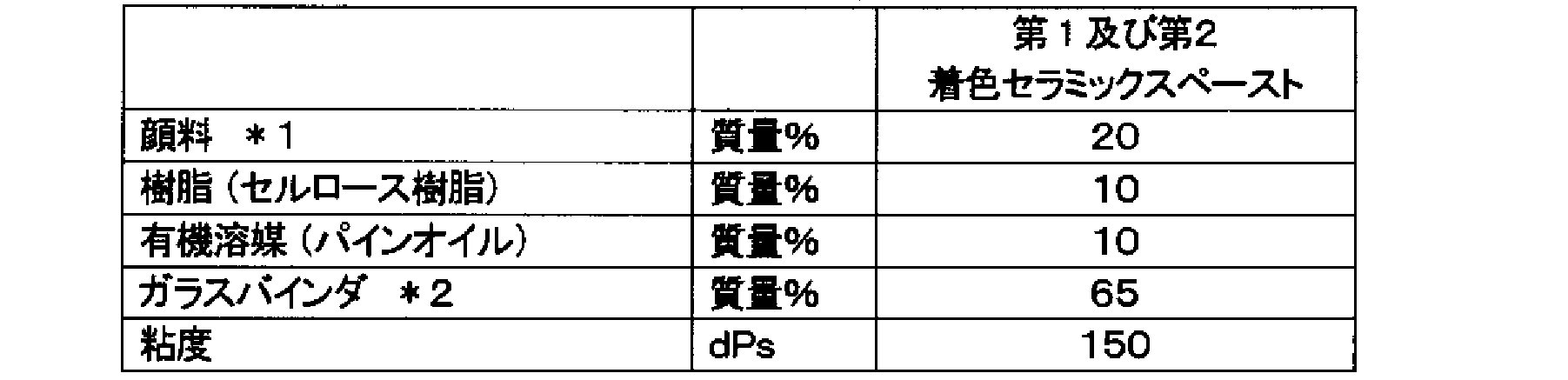
*1,主成分:酸化銅、酸化クロム、酸化鉄及び酸化マンガン
*2,主成分:ホウケイ酸ビスマス、ホウケイ酸亜鉛 The ceramic layers 241 and 243 can be formed of various materials. For example, the ceramic layers 241 and 243 can have the following composition.
* 1, Main component: Copper oxide, Chromium oxide, Iron oxide and Manganese oxide * 2, Main component: Bismuth borosilicate, Zinc borosilicate
*2,主成分:ホウケイ酸ビスマス、ホウケイ酸亜鉛 The
また、銀層242も、特には限定されないが、例えば、以下の組成とすることができる。
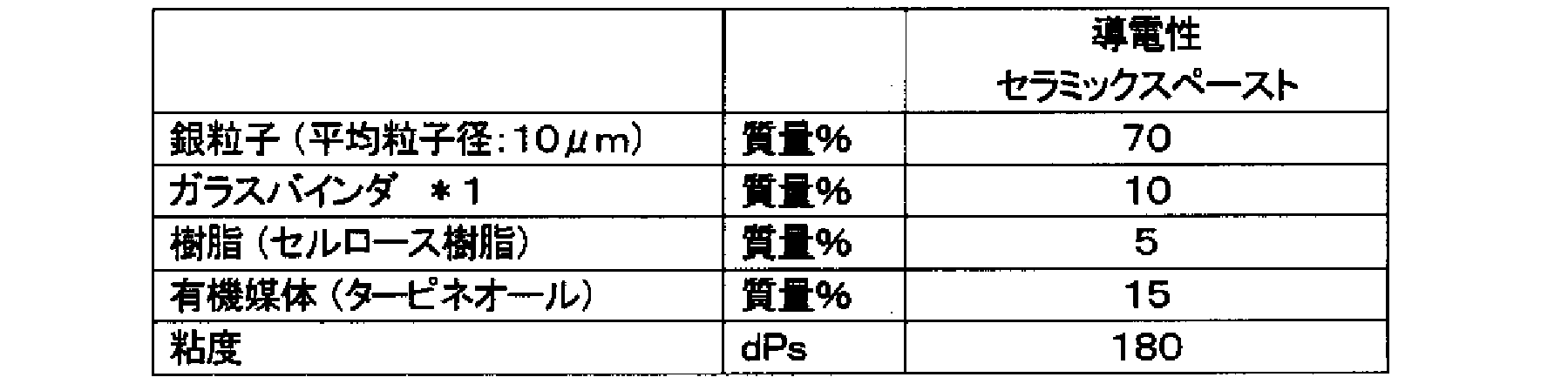
*1,主成分:ホウケイ酸ビスマス、ホウケイ酸亜鉛
In addition, the silver layer 242 is not particularly limited, and for example, the following composition can be used.
* 1, Main component: Bismuth borosilicate, Zinc borosilicate
スクリーン印刷の条件として、例えば、ポリエステルスクリーン:355メッシュ,コート厚み:20μm,テンション:20Nm,スキージ硬度:80度,取り付け角度:75°,印刷速度:300mm/sとすることができ、乾燥炉にて150℃、10分の乾燥により、セラミック層及び銀層を形成することができる。なお、第1セラミック層241、銀層242、及び第2セラミック層243をこの順で積層する場合には、上述したスクリーン印刷及び乾燥を繰り返せばよい。
As conditions for screen printing, for example, polyester screen: 355 mesh, coat thickness: 20 μm, tension: 20 Nm, squeegee hardness: 80 degrees, mounting angle: 75 °, printing speed: 300 mm / s, The ceramic layer and the silver layer can be formed by drying at 150 ° C. for 10 minutes. In addition, when laminating | stacking the 1st ceramic layer 241, the silver layer 242, and the 2nd ceramic layer 243 in this order, what is necessary is just to repeat screen printing and drying mentioned above.
<3.ウインドシールドの製造方法>
次に、ウインドシールドの製造方法について説明する。まず、ガラス板の製造ラインについて説明する。 <3. Windshield manufacturing method>
Next, a method for manufacturing the windshield will be described. First, a glass plate production line will be described.
次に、ウインドシールドの製造方法について説明する。まず、ガラス板の製造ラインについて説明する。 <3. Windshield manufacturing method>
Next, a method for manufacturing the windshield will be described. First, a glass plate production line will be described.
図9に示すように、この製造ラインには、上流から下流へ、加熱炉901、成形装置902がこの順で配置されている。そして、加熱炉901から成形装置902、及びその下流側に亘ってはローラコンベア903が配置されており、加工対象となるガラス板10は、このローラコンベア903により搬送される。ガラス板10は、加熱炉901に搬入される前には、平板状に形成されており、このガラス板10に上述したマスク層2が積層された後、加熱炉901に搬入される。
As shown in FIG. 9, a heating furnace 901 and a molding device 902 are arranged in this order from upstream to downstream in this production line. A roller conveyor 903 is arranged from the heating furnace 901 to the molding apparatus 902 and the downstream side thereof, and the glass plate 10 to be processed is conveyed by the roller conveyor 903. The glass plate 10 is formed in a flat plate shape before being carried into the heating furnace 901. After the mask layer 2 described above is laminated on the glass plate 10, the glass plate 10 is carried into the heating furnace 901.
加熱炉901は、種々の構成が可能であるが、例えば、電気加熱炉とすることができる。この加熱炉901は、上流側及び下流側の端部が開放する角筒状の炉本体を備えており、その内部に上流から下流へ向かってローラコンベア903が配置されている。炉本体の内壁面の上面、下面、及び一対の側面には、それぞれヒータ(図示省略)が配置されており、加熱炉901を通過するガラス板10を成形可能な温度、例えば、ガラスの軟化点付近まで加熱する。
The heating furnace 901 can have various configurations, but can be an electric heating furnace, for example. The heating furnace 901 includes a rectangular tube-shaped furnace main body whose upstream and downstream ends are open, and a roller conveyor 903 is disposed in the interior from upstream to downstream. Heaters (not shown) are disposed on the upper surface, the lower surface, and the pair of side surfaces of the inner wall surface of the furnace body, respectively, and the temperature at which the glass plate 10 passing through the heating furnace 901 can be formed, for example, the softening point of glass. Heat to near.
成形装置902は、上型921及び下型922によりガラス板をプレスし、所定の形状に成形するように構成されている。上型921はガラス板10の上面全体を覆うような下に凸の曲面形状を有し、上下動可能に構成されている。また、下型922はガラス板10の周縁部に対応するような枠状に形成されており、その上面は上型921と対応するように曲面形状を有している。この構成により、ガラス板10は、上型921と下型922との間でプレス成形され、最終的な曲面形状に成形される。また、下型922の枠内には、ローラコンベア903が配置されており、このローラコンベア903は、下型922の枠内を通過するように、上下動可能となっている。そして、図示を省略するが、成形装置902の下流側には、徐冷装置(図示省略)が配置されており、成形されたガラス板が冷却される。
The forming apparatus 902 is configured to press a glass plate with an upper die 921 and a lower die 922 to form a predetermined shape. The upper die 921 has a downwardly convex curved shape so as to cover the entire upper surface of the glass plate 10, and is configured to be movable up and down. The lower die 922 is formed in a frame shape corresponding to the peripheral edge of the glass plate 10, and the upper surface thereof has a curved shape so as to correspond to the upper die 921. With this configuration, the glass plate 10 is press-formed between the upper die 921 and the lower die 922, and formed into a final curved shape. A roller conveyor 903 is disposed in the frame of the lower mold 922, and the roller conveyor 903 can move up and down so as to pass through the frame of the lower mold 922. And although illustration is abbreviate | omitted, the slow cooling apparatus (illustration omitted) is arrange | positioned in the downstream of the shaping | molding apparatus 902, and the shape | molded glass plate is cooled.
上記のようなローラコンベア903は公知のものであり、両端部を回転自在に支持された複数のローラ931が、所定間隔をあけて配置されている。各ローラ931の駆動には種々の方法があるが、例えば、各ローラ931の端部にスプロケットを取り付け、各スプロケットにチェーンを巻回して駆動することができる。そして、各ローラ931の回転速度を調整することで、ガラス板10の搬送速度も調整することができる。なお、成形装置902の下型922はガラス板10の全面に亘って接するような形態でもよい。このほか、成形装置902は、ガラス板を成形するものであれば、上型及び下型の形態は特には限定されない。
The roller conveyor 903 as described above is a known one, and a plurality of rollers 931 whose both ends are rotatably supported are arranged at predetermined intervals. There are various methods for driving each roller 931. For example, a sprocket can be attached to the end of each roller 931, and a chain can be wound around each sprocket to drive it. And the conveyance speed of the glass plate 10 can also be adjusted by adjusting the rotational speed of each roller 931. FIG. Note that the lower mold 922 of the forming apparatus 902 may be in contact with the entire surface of the glass plate 10. In addition, if the shaping | molding apparatus 902 shape | molds a glass plate, the form of an upper mold | type and a lower mold | type will not be specifically limited.
こうして、外側ガラス板11及び内側ガラス板12が成形されると、これに続いて、中間膜13を外側ガラス板11及び内側ガラス板12の間に挟み、これをゴムバッグに入れ、減圧吸引しながら約70~110℃で予備接着する。予備接着の方法は、これ以外でも可能である。例えば、中間膜13を外側ガラス板11及び内側ガラス板12の間に挟み、オーブンにより45~65℃で加熱する。続いて、この合わせガラスを0.45~0.55MPaでロールにより押圧する。次に、この合わせガラスを、再度オーブンにより80~105℃で加熱した後、0.45~0.55MPaでロールにより再度押圧する。こうして、予備接着が完了する。
Thus, when the outer glass plate 11 and the inner glass plate 12 are formed, the intermediate film 13 is subsequently sandwiched between the outer glass plate 11 and the inner glass plate 12, put into a rubber bag, and sucked under reduced pressure. While pre-adhering at about 70-110 ° C. Other pre-adhesion methods are possible. For example, the intermediate film 13 is sandwiched between the outer glass plate 11 and the inner glass plate 12 and heated at 45 to 65 ° C. in an oven. Subsequently, this laminated glass is pressed by a roll at 0.45 to 0.55 MPa. Next, the laminated glass is again heated at 80 to 105 ° C. in an oven and then pressed again with a roll at 0.45 to 0.55 MPa. Thus, preliminary adhesion is completed.
次に、本接着を行う。予備接着がなされた合わせガラスを、オートクレーブにより、例えば、8~15気圧で、100~150℃によって、本接着を行う。具体的には、例えば、14気圧で145℃の条件で本接着を行うことができる。こうして、本実施形態に係る合わせガラスが製造される。
Next, this bonding is performed. The laminated glass that has been pre-adhered is subjected to main bonding by an autoclave at, for example, 8 to 15 atm and 100 to 150 ° C. Specifically, for example, the main bonding can be performed under the conditions of 14 atm and 145 ° C. Thus, the laminated glass according to the present embodiment is manufactured.
また、このような合わせガラスの自動車への取付において、合わせガラスの取付角度は、垂直から45度以下にすることが好ましい。
In addition, when mounting such a laminated glass to an automobile, the mounting angle of the laminated glass is preferably 45 degrees or less from the vertical.
<4.測定ユニット>
次に、測定ユニットについて、図10及び図11を参照しつつ説明する。図10はブラケットを車外側から見た斜視図、図11はブラケットを車内側から見た斜視図である。 <4. Measurement unit>
Next, the measurement unit will be described with reference to FIGS. FIG. 10 is a perspective view of the bracket as seen from the outside of the vehicle, and FIG. 11 is a perspective view of the bracket as seen from the inside of the vehicle.
この測定ユニット4は、ガラス板1の内面に固定されるブラケット(取付部材)5、このブラケット5に支持されるセンサ(図示省略)、及びブラケット5とセンサを車内側から覆うカバー(図示省略)に、により構成されている。
The measurement unit 4 includes a bracket (mounting member) 5 fixed to the inner surface of the glass plate 1, a sensor (not shown) supported by the bracket 5, and a cover (not shown) that covers the bracket 5 and the sensor from the inside of the vehicle. It is constituted by.
図10及び図11に示すように、ブラケット5は、センターマスク層22に固定される板状の固定部51と、この固定部51の車内側の面に設けられ、センサを支持する支持部52と、を備えている。固定部51は、横方向に延びる上辺部511と、この上辺部511の両側から下方に延びる一対の側辺部512,513と、両側辺部512,513の下端部同士を連結する下辺部514と、を備えており、全体として矩形状に形成されている。そして、各辺部512~514で囲まれる矩形状の前部開口53は、センターマスク層22の開口23と対応しており、この前部開口53からセンサにより光の照射及び光の受光が行われる。また、各辺部512~514においてセンターマスク層22側を向く面は、平坦に形成されており、センターマスク層22に接着される接着面を構成する。
As shown in FIGS. 10 and 11, the bracket 5 includes a plate-like fixing portion 51 fixed to the center mask layer 22 and a support portion 52 that is provided on the inner surface of the fixing portion 51 and supports the sensor. And. The fixing portion 51 includes an upper side portion 511 extending in the horizontal direction, a pair of side side portions 512 and 513 extending downward from both sides of the upper side portion 511, and a lower side portion 514 connecting the lower end portions of the both side sides 512 and 513. And is formed in a rectangular shape as a whole. A rectangular front opening 53 surrounded by the side portions 512 to 514 corresponds to the opening 23 of the center mask layer 22, and light is emitted and received by the sensor from the front opening 53. Is called. Further, in each of the side portions 512 to 514, the surface facing the center mask layer 22 side is formed flat and constitutes an adhesive surface bonded to the center mask layer 22.
図11に示すように、支持部52は、両側辺部512,513から車内側へ起立する一対の支持片521,522と、これら支持片521,522を連結する連結部523とを備えている。連結部523は、前部開口53と対応する位置に左右方向に延びるように配置されている。センサは、前部開口53を介して光の照射及び光の受光ができるように、両支持片521,522によって支持される。そして、図示を省略するが、このブラケット5には、車内側からカバーが取り付けられ、カバーによって、ブラケット5の車内側の面及びセンサが覆われる。一方、センターマスク層22が形成されているため、開口23を除いては、車外側からも測定ユニット4は見えないようになっている。
As shown in FIG. 11, the support portion 52 includes a pair of support pieces 521 and 522 that rise from the side portions 512 and 513 toward the vehicle interior, and a connecting portion 523 that connects the support pieces 521 and 522. . The connecting portion 523 is disposed at a position corresponding to the front opening 53 so as to extend in the left-right direction. The sensor is supported by both support pieces 521 and 522 so that light can be emitted and received through the front opening 53. And although illustration is abbreviate | omitted, a cover is attached to this bracket 5 from the vehicle inside, and the vehicle inner surface and sensor of the bracket 5 are covered with a cover. On the other hand, since the center mask layer 22 is formed, the measurement unit 4 cannot be seen from the outside of the vehicle except for the opening 23.
ところで、固定部51の接着面は、両面テープ及び接着剤によりセンターマスク層22に固定される。この点について、詳述する。図10に示すように、本実施形態に係るブラケット5では、接着面の4箇所に両面テープが貼り付けられるとともに、5箇所において線状の接着剤が塗布されている。各両面テープは、矩形状に形成され、4つの両面テープは、上辺部511の両側の2箇所にそれぞれ貼り付けられる第1及び第2両面テープ61,62、及び上辺部511と各側辺部512,513との連結部分の2箇所にそれぞれ貼り付けられる第3及び第4両面テープ63,64である。なお、各両面テープ61~64の厚みは、例えば、0.2~0.8mmであることが好ましい。これにより、ブラケット5がセンターマスク層22に押し付けられても、両面テープ61~64の厚みだけ接着面とセタンーマスク層22との間にクリアランスが確保される。その結果、接着剤の厚みを確保できるとともに、接着剤が押し潰されて広がりすぎないようにすることができる。
Incidentally, the adhesive surface of the fixing portion 51 is fixed to the center mask layer 22 with a double-sided tape and an adhesive. This point will be described in detail. As shown in FIG. 10, in the bracket 5 according to the present embodiment, a double-sided tape is affixed to four locations on the adhesive surface, and a linear adhesive is applied to the five locations. Each double-sided tape is formed in a rectangular shape, and the four double-sided tapes are attached to two locations on both sides of the upper side portion 511, respectively, the first and second double- sided tapes 61 and 62, and the upper side portion 511 and each side side portion. The third and fourth double- sided tapes 63 and 64 are affixed to two locations of the connecting portion with 512 and 513, respectively. The thickness of each double-sided tape 61-64 is preferably 0.2-0.8 mm, for example. Thus, even when the bracket 5 is pressed against the center mask layer 22, a clearance is secured between the adhesive surface and the cetane mask layer 22 by the thickness of the double-sided tapes 61 to 64. As a result, the thickness of the adhesive can be ensured, and the adhesive can be prevented from being crushed and spread too much.
一方、5つの接着剤は、第1及び第2両面テープ61,62の間に配置される第1接着剤71、第1及び第2両面テープ61,62の下側にそれぞれ配置される第2及び第3接着剤72,73、第3及び第4両面テープ63,64の下側にそれぞれ配置される第4及び第5接着剤74,75である。また、第1~第3接着剤71~73は、左右方向に延びるように塗布され、第4及び第5接着剤74,75は、上下方向に延びるように塗布されている。
On the other hand, the five adhesives are the first adhesive 71 disposed between the first and second double- sided tapes 61 and 62, and the second adhesive disposed below the first and second double- sided tapes 61 and 62, respectively. And third and fourth adhesives 72 and 73, and fourth and fifth adhesives 74 and 75 disposed below the third and fourth double- sided tapes 63 and 64, respectively. The first to third adhesives 71 to 73 are applied so as to extend in the left-right direction, and the fourth and fifth adhesives 74, 75 are applied so as to extend in the vertical direction.
そして、固定部51においては、上記各接着剤71~75が塗布される箇所に、貫通孔81~85がそれぞれ形成されている。各貫通孔81~85は、固定部51の車外側の面及び車内側の面に開放しており、カバーが取り付けられていない状態において、車内側から各貫通孔81~85を視認可能となっている。そして、上記各接着剤71~75は、貫通孔81~85を通過するように塗布される。
In the fixing portion 51, through holes 81 to 85 are formed at locations where the adhesives 71 to 75 are applied. The through holes 81 to 85 are open to the vehicle outer surface and the vehicle inner surface of the fixed portion 51, so that the through holes 81 to 85 can be visually recognized from the vehicle inner side when the cover is not attached. ing. The adhesives 71 to 75 are applied so as to pass through the through holes 81 to 85.
続いて、接着剤及び貫通孔の寸法について、図12を参照しつつ説明する。同図に示すように、上記各接着剤71~75の幅D2は、特には限定されないが、2~3mmの幅で塗布されると、ブラケット5がセンターマスク層22に押し付けられて接着されたときに、概ね10mm程度の幅D1まで押し広がる。ここで、接着剤71が押し広げられた後の領域を押し広がり領域70と称し、以下の説明でも同じである。また、貫通孔81~85の形状は、矩形、円形、楕円、多角形状など、種々の形状にすることができるが、少なくとも、接着面への塗布時に、貫通孔81~85で分断されないように、貫通孔81~85を越えて接着剤71~75が塗布されることが必要である。そのため、貫通孔における接着剤71~75が延びる方向の径D3は、例えば、接着剤71~75の幅が2~3mmであれば、2~5mmであることが好ましい。
Subsequently, the dimensions of the adhesive and the through hole will be described with reference to FIG. As shown in the figure, the width D2 of each of the adhesives 71 to 75 is not particularly limited, but when applied with a width of 2 to 3 mm, the bracket 5 is pressed against and adhered to the center mask layer 22. Sometimes it spreads to a width D1 of about 10 mm. Here, the region after the adhesive 71 is spread is referred to as a spread region 70, and the same applies to the following description. The shape of the through holes 81 to 85 can be various shapes such as a rectangle, a circle, an ellipse, and a polygon, but at least when being applied to the adhesive surface, the through holes 81 to 85 are not divided. The adhesives 71 to 75 need to be applied beyond the through holes 81 to 85. Therefore, the diameter D3 of the through holes in the direction in which the adhesives 71 to 75 extend is preferably 2 to 5 mm if the width of the adhesives 71 to 75 is 2 to 3 mm, for example.
なお、接着剤71~75は、種々のものを採用できるが、例えば、ウレタン樹脂接着剤、エポキシ樹脂接着剤などを用いることができる。但し、エポキシ樹脂接着剤は粘性が高いため、流れにくく、有利である。
Note that various adhesives 71 to 75 can be employed. For example, a urethane resin adhesive, an epoxy resin adhesive, or the like can be used. However, the epoxy resin adhesive is advantageous because it is difficult to flow because of its high viscosity.
次に、センサについて説明する。このセンサは、公知のものを利用することができる。図示を含め、具体的な態様は省略するが、例えば、レーザ発光素子からレーザ光を照射し、先行する車や障害物などで反射された反射光を受光レンズを介して受光素子で受光するように構成することができる。そして、反射光を、受光素子で受光するまでの時間に基づいて、先行車両や障害物と自車との距離を算出する。算出された距離はセンサから外部機器に送信され、ブレーキの制御などに用いられる。
Next, the sensor will be described. A known sensor can be used as this sensor. Although specific embodiments including illustration are omitted, for example, laser light is emitted from a laser light emitting element, and reflected light reflected by a preceding car or obstacle is received by the light receiving element via a light receiving lens. Can be configured. Based on the time until the reflected light is received by the light receiving element, the distance between the preceding vehicle or the obstacle and the host vehicle is calculated. The calculated distance is transmitted from the sensor to an external device and used for brake control and the like.
上記ブラケット5は、上記のように、ガラス板1のマスク層2上に、接着剤71~75と両面テープ61~64により固定され、本実施形態に係るガラス板モジュールとなる。その後、このガラス板モジュールには、センサ及びカバーが取付けられ、ウインドウモジュールが構成される。また、具体的な車両の製造工程として、ガラス板モジュールが車両の前面部の窓枠に固定された後、ブラケット5にセンサ及びカバーが取付けられる。この際、センサの配線も行われる。
As described above, the bracket 5 is fixed on the mask layer 2 of the glass plate 1 with the adhesives 71 to 75 and the double-sided tapes 61 to 64, thereby forming the glass plate module according to the present embodiment. Thereafter, a sensor and a cover are attached to the glass plate module to constitute a window module. As a specific vehicle manufacturing process, the sensor and cover are attached to the bracket 5 after the glass plate module is fixed to the window frame on the front surface of the vehicle. At this time, sensor wiring is also performed.
<5.特徴>
以上のように、本実施形態によれば、ブラケット5の固定部51に貫通孔81~85を形成し、この貫通孔81~85を通過するように接着剤71~75が塗布されている。そのため、ブラケット5をセンターマスク層22に固定した後に、図13に示すように、車内側から貫通孔81を介して接着剤71の有無を確認することができる。特に、センサの重量は軽くないため、接着剤を塗布せず、両面テープ61~64だけでブラケット5をマスク層2に固定すると、接着強度不足により、ブラケット5がセンターマスク層22から離脱するおそれがある。したがって、接着剤の有無の確認は非常に重要となる。また、上述した製造工程では、ガラス板モジュールを車両に取付ける作業者と、センサをブラケット5に取付ける作業者とは相違することが多いため、接着剤の有無の確認はいずれの工程においても容易に行われるべき必要がある。これは、例えば、センサをブラケットに取付ける作業者が、接着剤の塗布忘れに気付いた場合には、ガラス板モジュールを車両から取り外す必要があり、車両の製造に与える影響が大きいためである。 <5. Features>
As described above, according to the present embodiment, the throughholes 81 to 85 are formed in the fixing portion 51 of the bracket 5, and the adhesives 71 to 75 are applied so as to pass through the through holes 81 to 85. Therefore, after fixing the bracket 5 to the center mask layer 22, the presence or absence of the adhesive 71 can be confirmed from the inside of the vehicle via the through hole 81 as shown in FIG. 13. In particular, since the weight of the sensor is not light, if the bracket 5 is fixed to the mask layer 2 with only the double-sided tapes 61 to 64 without applying an adhesive, the bracket 5 may be detached from the center mask layer 22 due to insufficient adhesive strength. There is. Therefore, confirmation of the presence or absence of adhesive is very important. Further, in the above-described manufacturing process, an operator who attaches the glass plate module to the vehicle is often different from an operator who attaches the sensor to the bracket 5, so it is easy to check the presence or absence of the adhesive in any process. Need to be done. This is because, for example, when an operator who attaches the sensor to the bracket notices forgetting to apply the adhesive, it is necessary to remove the glass plate module from the vehicle, which has a great influence on the manufacture of the vehicle.
以上のように、本実施形態によれば、ブラケット5の固定部51に貫通孔81~85を形成し、この貫通孔81~85を通過するように接着剤71~75が塗布されている。そのため、ブラケット5をセンターマスク層22に固定した後に、図13に示すように、車内側から貫通孔81を介して接着剤71の有無を確認することができる。特に、センサの重量は軽くないため、接着剤を塗布せず、両面テープ61~64だけでブラケット5をマスク層2に固定すると、接着強度不足により、ブラケット5がセンターマスク層22から離脱するおそれがある。したがって、接着剤の有無の確認は非常に重要となる。また、上述した製造工程では、ガラス板モジュールを車両に取付ける作業者と、センサをブラケット5に取付ける作業者とは相違することが多いため、接着剤の有無の確認はいずれの工程においても容易に行われるべき必要がある。これは、例えば、センサをブラケットに取付ける作業者が、接着剤の塗布忘れに気付いた場合には、ガラス板モジュールを車両から取り外す必要があり、車両の製造に与える影響が大きいためである。 <5. Features>
As described above, according to the present embodiment, the through
なお、上記のように、貫通孔の形状は、特には限定されないが、接着剤の色によっては、貫通孔全体に接着剤が充填されると、接着剤の有無が視認しがたい場合がある。これに対して、例えば、図14に示すように、接着剤7の延びる第1方向Xよりも、これと交差する第2方向Yの長さが長い貫通孔8を形成すると、接着剤7の確認が容易になる。このようにすると、接着剤7が押し潰されても、貫通孔8の第2方向Y全体には接着剤7が入り込まないため、貫通孔8の内部に、接着剤7が存在する箇所と、存在しない箇所とが生じ、これらは見え方が異なる。そのため、接着剤7が存在している場合には、2つの箇所が視認できるため、接着剤7の存在を容易に視認することができる。なお、貫通孔の方向は、第2方向と完全に一致していなくてもよく、傾斜していてもよい。
As described above, the shape of the through hole is not particularly limited. However, depending on the color of the adhesive, when the entire through hole is filled with the adhesive, it may be difficult to visually recognize the presence or absence of the adhesive. . On the other hand, for example, as shown in FIG. 14, when the through hole 8 having a length in the second direction Y intersecting with the first direction X in which the adhesive 7 extends is longer, Confirmation becomes easy. In this way, even if the adhesive 7 is crushed, the adhesive 7 does not enter the entire second direction Y of the through-hole 8, and therefore the location where the adhesive 7 exists inside the through-hole 8, There are places that do not exist, and they look different. Therefore, when the adhesive 7 is present, two locations can be visually recognized, so the presence of the adhesive 7 can be easily visually confirmed. Note that the direction of the through hole may not be completely coincident with the second direction, and may be inclined.
<6.変形例>
以上、本発明の一実施形態について説明したが、本発明は上記実施形態に限定されるものではなく、その趣旨を逸脱しない限りにおいて、種々の変更が可能である。なお、以下の変形例は、適宜組合せが可能である。 <6. Modification>
As mentioned above, although one Embodiment of this invention was described, this invention is not limited to the said embodiment, A various change is possible unless it deviates from the meaning. Note that the following modifications can be combined as appropriate.
<6-1>
上記実施形態では、接着剤の有無を確認するための一例を示したが、他の態様も可能である。例えば、図15に示すように、ブラケット5の固定部51の縁部に切欠き87を形成し、この切欠き87の近傍を通過するように、接着剤7を塗布する。このようにすると、ブラケット5がマスク層2に固定され、接着剤7が押し広げられたときに、接着剤7が切欠き87内へはみ出るため、車内側から接着剤7の有無を視認することができる。すなわち、接着剤7の押し広がり領域70と切欠き87とが重なる部分700が視認可能となる。接着剤7と切欠き87との距離dは特には限定されないが、接着剤7が押し広げられる幅を考慮して、0~3mm程度であることが好ましい。 <6-1>
In the above embodiment, an example for confirming the presence or absence of an adhesive is shown, but other modes are also possible. For example, as shown in FIG. 15, anotch 87 is formed at the edge of the fixed portion 51 of the bracket 5, and the adhesive 7 is applied so as to pass near the notch 87. In this way, when the bracket 5 is fixed to the mask layer 2 and the adhesive 7 is pushed and spread, the adhesive 7 protrudes into the notch 87, so that the presence or absence of the adhesive 7 is visually recognized from the inside of the vehicle. Can do. That is, a portion 700 where the spread area 70 of the adhesive 7 and the notch 87 overlap is visible. The distance d between the adhesive 7 and the notch 87 is not particularly limited, but is preferably about 0 to 3 mm in consideration of the width in which the adhesive 7 is spread.
上記実施形態では、接着剤の有無を確認するための一例を示したが、他の態様も可能である。例えば、図15に示すように、ブラケット5の固定部51の縁部に切欠き87を形成し、この切欠き87の近傍を通過するように、接着剤7を塗布する。このようにすると、ブラケット5がマスク層2に固定され、接着剤7が押し広げられたときに、接着剤7が切欠き87内へはみ出るため、車内側から接着剤7の有無を視認することができる。すなわち、接着剤7の押し広がり領域70と切欠き87とが重なる部分700が視認可能となる。接着剤7と切欠き87との距離dは特には限定されないが、接着剤7が押し広げられる幅を考慮して、0~3mm程度であることが好ましい。 <6-1>
In the above embodiment, an example for confirming the presence or absence of an adhesive is shown, but other modes are also possible. For example, as shown in FIG. 15, a
切欠き87は、種々の形態にすることができ、図16に示すように、矩形状、円弧状、多角形状などにすることができる。また、接着剤7の数、塗布位置、塗布形状も、一部が切欠きからはみ出するのであれば、特には限定されない。なお、図15に示すように、接着剤7は、切欠き87において、固定部51の縁部から最も離れた位置を通過するように塗布することが好ましい。このようにすると、接着剤7が押し広げられても、切欠き87内にのみ入り込み、固定部51の縁部よりも外側にはみ出るのを防止できる。
The notch 87 can have various forms, and can be rectangular, arcuate, polygonal, etc., as shown in FIG. Further, the number of adhesives 7, the application position, and the application shape are not particularly limited as long as part of the adhesive 7 protrudes from the notch. As shown in FIG. 15, it is preferable that the adhesive 7 is applied so as to pass through the notch 87 through a position farthest from the edge of the fixing portion 51. In this way, even if the adhesive 7 is spread out, it can be prevented from entering only into the notch 87 and protruding beyond the edge of the fixed portion 51.
<6-2>
また、ブラケット5の形状を変えず、接着剤の塗布形状を変えることで、接着剤の有無を確認することもできる。例えば、図17に示すように、接着剤7を、固定部51の縁部に沿う本体部711と、この本体部711から固定部51の縁部まで延びる延在部712とを備えたL字状に形成することができる。このとき、本体部711の延びる方向の長さL1は、延在部712の同方向の長さL2よりも長くする。これにより、ブラケット5がマスク層22に固定され、接着剤7が押し広げられたときに、接着剤7の延在部712が固定部51の縁部からはみ出すため、車内側から接着剤7の有無を視認することができる。すなわち、延在部712に基づく押し広がり領域70の一部が、固定部51の縁部からはみ出すため(符号700)、視認可能となる。このとき、固定部51の縁部において、押し広がり領域70からの接着剤のはみ出しを視認できる部分が本発明の接着剤確認部となる。なお、接着剤7としては、本体部711がブラケット5の固定としての機能を有し、延在部712は接着剤の有無を確認するためのものであるため、はみ出すための最小の形状であればよい。そのため、延在部の長さL2は、できるだけ小さいことが好ましい。また、延在部712は、固定部51の縁部の近傍まで達していればよく、押し広がり領域70が縁部からはみ出すのであれば、縁部と接触していなくてもよい。 <6-2>
Moreover, the presence or absence of an adhesive can also be confirmed by changing the application shape of the adhesive without changing the shape of thebracket 5. For example, as shown in FIG. 17, the adhesive 7 includes an L-shaped body including a main body 711 extending along the edge of the fixing portion 51 and an extending portion 712 extending from the main body 711 to the edge of the fixing portion 51. Can be formed. At this time, the length L1 in the extending direction of the main body 711 is longer than the length L2 of the extending portion 712 in the same direction. Thereby, when the bracket 5 is fixed to the mask layer 22 and the adhesive 7 is pushed and spread, the extending portion 712 of the adhesive 7 protrudes from the edge of the fixing portion 51, so that the adhesive 7 The presence or absence can be visually recognized. That is, a part of the spread area 70 based on the extending part 712 protrudes from the edge of the fixed part 51 (reference numeral 700), and thus can be visually recognized. At this time, a portion where the protrusion of the adhesive from the spread area 70 can be visually recognized at the edge of the fixing portion 51 becomes the adhesive confirmation portion of the present invention. As the adhesive 7, the main body portion 711 has a function of fixing the bracket 5, and the extension portion 712 is for confirming the presence or absence of the adhesive, so that it may have a minimum shape for protruding. That's fine. Therefore, it is preferable that the length L2 of the extending portion is as small as possible. Moreover, the extension part 712 should just reach the vicinity of the edge part of the fixing | fixed part 51, and if the spreading area 70 protrudes from an edge part, it does not need to contact the edge part.
また、ブラケット5の形状を変えず、接着剤の塗布形状を変えることで、接着剤の有無を確認することもできる。例えば、図17に示すように、接着剤7を、固定部51の縁部に沿う本体部711と、この本体部711から固定部51の縁部まで延びる延在部712とを備えたL字状に形成することができる。このとき、本体部711の延びる方向の長さL1は、延在部712の同方向の長さL2よりも長くする。これにより、ブラケット5がマスク層22に固定され、接着剤7が押し広げられたときに、接着剤7の延在部712が固定部51の縁部からはみ出すため、車内側から接着剤7の有無を視認することができる。すなわち、延在部712に基づく押し広がり領域70の一部が、固定部51の縁部からはみ出すため(符号700)、視認可能となる。このとき、固定部51の縁部において、押し広がり領域70からの接着剤のはみ出しを視認できる部分が本発明の接着剤確認部となる。なお、接着剤7としては、本体部711がブラケット5の固定としての機能を有し、延在部712は接着剤の有無を確認するためのものであるため、はみ出すための最小の形状であればよい。そのため、延在部の長さL2は、できるだけ小さいことが好ましい。また、延在部712は、固定部51の縁部の近傍まで達していればよく、押し広がり領域70が縁部からはみ出すのであれば、縁部と接触していなくてもよい。 <6-2>
Moreover, the presence or absence of an adhesive can also be confirmed by changing the application shape of the adhesive without changing the shape of the
また、このような接着剤の形状は、種々の態様が可能である。例えば、図18に示すように、必ずしもL字状にする必要はなく、J字状やT字状であってもよい。
Moreover, various forms are possible for the shape of such an adhesive. For example, as shown in FIG. 18, it is not necessarily L-shaped, and it may be J-shaped or T-shaped.
<6-3>
接着面に塗布されたときの接着剤の形状は、上記のような直線状のみならず、波線、破線状、あるいは帯状、矩形状、円形状、多角形状、など、種々の形状にすることができる。また、接着剤の数も特には限定されない。両面テープについても同様であり、その数、形状は特には限定されない。 <6-3>
The shape of the adhesive when applied to the adhesive surface is not limited to the linear shape as described above, but can be made into various shapes such as a wavy line, a broken line shape, a belt shape, a rectangular shape, a circular shape, and a polygonal shape. it can. Further, the number of adhesives is not particularly limited. The same applies to the double-sided tape, and the number and shape are not particularly limited.
<6-4>
上記実施形態では、本発明の情報取得装置として、車間距離を測定するセンサを用いたが、これに限定されるものではなく、種々の情報取得装置を用いることができる。すなわち、車外からの情報を取得するために、光の照射及び/または受光を行うものであれば、特には限定されない。例えば、車間距離を測定するための可視光線及び/又は赤外線カメラ、光ビーコンなどの車外からの信号を受信する受光装置、道路の白線等を画像にて読み取る可視光線及び/又は赤外線を使用したカメラなど、種々の装置に適用することができる。また、センターマスク層22には、光の種類に応じて、複数の開口を設けることもできる。なお、情報取得装置はガラスに接触していても接触していなくても良い。 <6-4>
In the above embodiment, the sensor for measuring the inter-vehicle distance is used as the information acquisition device of the present invention. However, the present invention is not limited to this, and various information acquisition devices can be used. That is, there is no particular limitation as long as light is emitted and / or received in order to acquire information from outside the vehicle. For example, a visible light and / or infrared camera for measuring the distance between vehicles, a light receiving device for receiving a signal from outside the vehicle such as an optical beacon, a camera using visible light and / or infrared light that reads a white line on a road in an image, etc. The present invention can be applied to various devices. Thecenter mask layer 22 can be provided with a plurality of openings according to the type of light. Note that the information acquisition device may or may not be in contact with the glass.
上記実施形態では、本発明の情報取得装置として、車間距離を測定するセンサを用いたが、これに限定されるものではなく、種々の情報取得装置を用いることができる。すなわち、車外からの情報を取得するために、光の照射及び/または受光を行うものであれば、特には限定されない。例えば、車間距離を測定するための可視光線及び/又は赤外線カメラ、光ビーコンなどの車外からの信号を受信する受光装置、道路の白線等を画像にて読み取る可視光線及び/又は赤外線を使用したカメラなど、種々の装置に適用することができる。また、センターマスク層22には、光の種類に応じて、複数の開口を設けることもできる。なお、情報取得装置はガラスに接触していても接触していなくても良い。 <6-4>
In the above embodiment, the sensor for measuring the inter-vehicle distance is used as the information acquisition device of the present invention. However, the present invention is not limited to this, and various information acquisition devices can be used. That is, there is no particular limitation as long as light is emitted and / or received in order to acquire information from outside the vehicle. For example, a visible light and / or infrared camera for measuring the distance between vehicles, a light receiving device for receiving a signal from outside the vehicle such as an optical beacon, a camera using visible light and / or infrared light that reads a white line on a road in an image, etc. The present invention can be applied to various devices. The
また、ブラケット5の形態は、上述したものに限定されず、種々の態様が可能である。例えば、情報取得装置としてカメラを用いる場合には、開口は1つでもよいし、複数の情報取得装置を用いる場合には2以上の開口があってもよい。すなわち、情報取得装置を支持し、少なくとも1つの周囲が閉じた開口または周囲の一部が開放した開口を有するとともに、マスク層と対向する接着面を備えた固定部を有し、両面テープ及び接着剤が塗布可能であれば、その形状は特には限定されない。
Moreover, the form of the bracket 5 is not limited to that described above, and various forms are possible. For example, when a camera is used as the information acquisition device, the number of openings may be one, and when a plurality of information acquisition devices are used, there may be two or more openings. That is, the information acquisition device is supported and has at least one opening that is closed at the periphery or an opening that is partially open at the periphery, and has a fixing portion having an adhesive surface facing the mask layer. The shape is not particularly limited as long as the agent can be applied.
<6-5>
マスク層2は、上記のように3層の構成を行っているが、これに限定されない。すなわち、上記実施形態では、電磁波を遮蔽するために、銀層242を設けたが、銀とセラミック層を混ぜ合わせた単層を設ける方法や、電磁波を遮蔽できるのであれば、他の材料、例えば、銅やニッケルなどを積層してもよい。また、銀層242が外部から見えないようにするためにセラミック層で挟んでいるが、セラミック層で覆う以外に、上述したカバーなどの部材を用いることもできる。また、必ずしも電磁波の遮蔽層を設けなくてもよく、少なくとも外部から見えないような層が形成されていればよい。さらに、上述した歪みが生じる領域を隠すために、銀層を塗布することもできる。 <6-5>
Themask layer 2 has a three-layer structure as described above, but is not limited to this. That is, in the above embodiment, the silver layer 242 is provided in order to shield electromagnetic waves, but other materials such as a method of providing a single layer in which silver and a ceramic layer are mixed, or an electromagnetic wave can be shielded. Copper, nickel, etc. may be laminated. In addition, the silver layer 242 is sandwiched between ceramic layers so that the silver layer 242 cannot be seen from the outside. However, in addition to covering with the ceramic layer, a member such as the cover described above can also be used. Further, it is not always necessary to provide an electromagnetic wave shielding layer, and at least a layer that cannot be seen from the outside may be formed. Further, a silver layer can be applied to hide the above-described region where distortion occurs.
マスク層2は、上記のように3層の構成を行っているが、これに限定されない。すなわち、上記実施形態では、電磁波を遮蔽するために、銀層242を設けたが、銀とセラミック層を混ぜ合わせた単層を設ける方法や、電磁波を遮蔽できるのであれば、他の材料、例えば、銅やニッケルなどを積層してもよい。また、銀層242が外部から見えないようにするためにセラミック層で挟んでいるが、セラミック層で覆う以外に、上述したカバーなどの部材を用いることもできる。また、必ずしも電磁波の遮蔽層を設けなくてもよく、少なくとも外部から見えないような層が形成されていればよい。さらに、上述した歪みが生じる領域を隠すために、銀層を塗布することもできる。 <6-5>
The
マスク層2は、黒以外でも可能であり、車外からの視野を遮蔽し、車内側が見えないような茶色、灰色、濃紺などの濃色であれば、特には限定されない。また、セラミックの代わりに、遮蔽用のフィルムを貼り付けることもできる。このようなフィルムは、例えば、濃色の樹脂製フィルムとすることができる。具体的には、ポリ塩化ビニル、ポリウレタン、ポリエチレン、ポリエチレンテレフタレートなどで形成することができ、接着剤によりガラス板1に貼り付けられる。接着剤は特には限定されないが、アクリル系接着剤などを用いることができる。このような遮蔽フィルムとしては、例えば、住友3M社製のABF Film,FTW9953J Film,Black Filmなどを用いることができる。なお、遮蔽フィルムとセラミック層とを組み合わせて、マスク層2を構成してもよい。
The mask layer 2 can be other than black, and is not particularly limited as long as it is a dark color such as brown, gray, or dark blue that blocks the field of view from the outside of the vehicle and prevents the inside of the vehicle from being seen. In addition, a shielding film can be attached instead of ceramic. Such a film can be, for example, a dark resin film. Specifically, it can be formed of polyvinyl chloride, polyurethane, polyethylene, polyethylene terephthalate or the like, and is attached to the glass plate 1 with an adhesive. The adhesive is not particularly limited, but an acrylic adhesive or the like can be used. As such a shielding film, for example, ABF Film, FTW9953J Film, Black Film manufactured by Sumitomo 3M Co., Ltd. can be used. In addition, you may comprise the mask layer 2 combining a shielding film and a ceramic layer.
上記実施形態では、マスク層2がガラス板の内側(内側ガラス板12の内面)に形成されている場合に、ブラケット41をマスク層2に対して固定した例を説明したが、例えば、合わせガラスにおいて、外側ガラス板11の内面、または内側ガラス板12の外面にマスク層2が形成されている場合には、ブラケット41は、内側ガラス板12の内面において、マスク層2が形成されている位置と対応する位置に固定される。
Although the said embodiment demonstrated the example which fixed the bracket 41 with respect to the mask layer 2 when the mask layer 2 is formed in the inner side (inner surface of the inner side glass plate 12) of a glass plate, for example, a laminated glass When the mask layer 2 is formed on the inner surface of the outer glass plate 11 or the outer surface of the inner glass plate 12, the bracket 41 is positioned at the inner surface of the inner glass plate 12 where the mask layer 2 is formed. And are fixed at corresponding positions.
<6-6>
上記実施形態では、本発明の第2接着手段として両面テープを用いたが、これに限定されない。すなわち、接着剤が硬化前の仮固定を行うように構成されているものであれば、第2接着手段として適用することができ、例えば、両面に速乾性の接着剤を塗布したゴムなどを用いることができる。これにより、接着面とマスク層との間のクリアランスも確保することができる。 <6-6>
In the said embodiment, although the double-sided tape was used as the 2nd adhesion | attachment means of this invention, it is not limited to this. That is, as long as the adhesive is configured to perform temporary fixing before curing, it can be applied as the second bonding means, for example, rubber with a fast-drying adhesive applied on both sides is used. be able to. Thereby, the clearance between an adhesion surface and a mask layer is also securable.
1 ガラス板
2 マスク層
22 センターマスク層
5 ブラケット(取付部材)
61~64 両面テープ(第2接着手段)
71~75 接着剤(第1接着手段) 1Glass plate 2 Mask layer 22 Center mask layer 5 Bracket (mounting member)
61-64 Double-sided tape (second bonding means)
71-75 Adhesive (first bonding means)
2 マスク層
22 センターマスク層
5 ブラケット(取付部材)
61~64 両面テープ(第2接着手段)
71~75 接着剤(第1接着手段) 1
61-64 Double-sided tape (second bonding means)
71-75 Adhesive (first bonding means)
Claims (12)
- 車両に取付けられるガラス板モジュールであって、
外側ガラス板、中間膜、及び内側ガラス板がこの順で積層された合わせガラスと、
前記合わせガラスに設けられ、外部からの視野を遮蔽するマスク層と、
前記内側ガラス板において前記マスク層と対応する部分に、少なくとも第1及び第2接着手段により取付けられ、車外からの情報を取得する情報取得装置を支持する取付部材と、
を備え、
前記第1接着手段は、少なくとも1つの接着剤を含み、
前記第2接着手段は、前記接着剤が硬化前の仮固定を行うように構成され、
前記取付部材は、前記マスク層と対向し前記両接着手段が設けられる接着面を有する固定部を備え、
前記固定部は、前記接着面に塗布された前記接着剤を車内側から視認可能な少なくとも1つの接着剤確認部を有している、ガラス板モジュール。 A glass plate module attached to a vehicle,
A laminated glass in which an outer glass plate, an intermediate film, and an inner glass plate are laminated in this order;
A mask layer that is provided on the laminated glass and shields a visual field from the outside;
An attachment member that is attached to the portion corresponding to the mask layer in the inner glass plate by at least first and second adhesive means and supports an information acquisition device that acquires information from outside the vehicle;
With
The first adhesive means comprises at least one adhesive;
The second bonding means is configured such that the adhesive performs temporary fixing before curing,
The mounting member includes a fixing portion having an adhesive surface facing the mask layer and provided with the both adhesive means,
The said fixing | fixed part is a glass plate module which has the at least 1 adhesive confirmation part which can visually recognize the said adhesive agent apply | coated to the said adhesive surface from the vehicle inside. - 前記第2接着手段は、厚さ0.2mm以上0.8mm以下の少なくとも1つの両面テープである、請求項1に記載のガラス板モジュール。 The glass plate module according to claim 1, wherein the second adhesion means is at least one double-sided tape having a thickness of 0.2 mm or more and 0.8 mm or less.
- 前記接着剤確認部は、前記固定部に形成された貫通孔により構成されており、
前記接着剤の塗布領域及び押し広がり領域の少なくとも一部は、前記接着面において、貫通孔と交差する、請求項1または2に記載のガラス板モジュール。 The adhesive confirmation part is constituted by a through hole formed in the fixing part,
3. The glass plate module according to claim 1, wherein at least a part of the adhesive application area and the spread area intersects the through hole in the adhesion surface. - 前記接着剤は、前記貫通孔と交差するように線状に塗布され、
前記貫通孔の外形は、前記接着剤の延びる第1方向の長さが、前記第1方向と直交する第2方向の長さよりも短くなるように形成されている、請求項3に記載のガラス板モジュール。 The adhesive is applied linearly so as to intersect the through hole,
4. The glass according to claim 3, wherein an outer shape of the through hole is formed such that a length in a first direction in which the adhesive extends is shorter than a length in a second direction orthogonal to the first direction. Board module. - 前記接着剤確認部は、前記固定部の縁部に形成された切欠きによって構成されており、
前記接着剤の塗布領域及び押し広がり領域の少なくとも一部は、前記接着面において、前記切欠きと重複する、請求項1または2に記載のガラス板モジュール。 The adhesive confirmation part is constituted by a notch formed in an edge part of the fixed part,
3. The glass plate module according to claim 1, wherein at least a part of the adhesive application area and the spread area overlaps the notch on the adhesion surface. 4. - 前記固定部の外縁から最も離れた位置の近傍を通過するように、前記接着剤が線状に塗布されている、請求項5に記載のガラス板モジュール。 The glass plate module according to claim 5, wherein the adhesive is applied linearly so as to pass through the vicinity of the position farthest from the outer edge of the fixed portion.
- 前記切欠きは、円弧状に形成されている、請求項6に記載のガラス板モジュール。 The glass plate module according to claim 6, wherein the notch is formed in an arc shape.
- 前記接着剤は、前記接着面に塗布されたときに、本体部と、当該本体部から前記固定部の縁部又はその近傍まで延びる延在部とで、構成されており、
前記固定部の縁部において、前記延在部が達する箇所が、前記接着剤確認部を構成する、請求項1または2に記載のガラス板モジュール。 The adhesive is composed of a main body part and an extending part extending from the main body part to an edge of the fixing part or the vicinity thereof when applied to the adhesive surface;
The glass plate module of Claim 1 or 2 in which the location where the said extension part reaches in the edge part of the said fixing | fixed part comprises the said adhesive confirmation part. - 前記本体部は、一方向に延びるように形成され、
前記延在部において前記本体部の延びる方向の長さは、前記本体部の長さよりも短い、請求項8に記載のガラス板モジュール。 The main body is formed to extend in one direction,
The glass plate module according to claim 8, wherein a length of the extending portion in a direction in which the main body portion extends is shorter than a length of the main body portion. - 前記マスク層は、濃色のセラミックス膜により形成されている、請求項1から9のいずれかに記載のガラス板モジュール。 The glass plate module according to any one of claims 1 to 9, wherein the mask layer is formed of a dark ceramic film.
- 車両に取付けられ、車外からの情報を取得する情報取得装置を備えたウインドウモジュールの製造方法であって、
外側ガラス板、中間膜、及び内側ガラス板がこの順で積層された合わせガラスと、
前記合わせガラスに設けられ、外部からの視野を遮蔽するマスク層と、
前記内側ガラス板において前記マスク層と対応する部分に、少なくとも1つの第1及び第2接着手段により取付けられ、前記情報取得装置を支持する取付部材と、
を備えるガラス板モジュールを準備する工程と、
前記情報取得装置を、前記取付部材を介して前記内側ガラス板側に設置する工程と、
を具備し、
前記第1接着手段は、少なくとも1つの接着剤を含み、
前記第2接着手段は、前記接着剤が硬化前の仮固定を行うように構成され、
前記取付部材は、前記マスク層と対向し前記両接着手段が設けられる接着面を有する固定部を備え、
前記固定部は、前記接着面に塗布された前記接着剤を車内側から視認可能な少なくとも1つの接着剤確認部を有する、情報取得装置を備えたウインドウモジュールの製造方法。 A method for manufacturing a window module provided with an information acquisition device that is attached to a vehicle and acquires information from outside the vehicle,
A laminated glass in which an outer glass plate, an intermediate film, and an inner glass plate are laminated in this order;
A mask layer that is provided on the laminated glass and shields a visual field from the outside;
An attachment member attached to the portion corresponding to the mask layer in the inner glass plate by at least one first and second adhesive means, and supporting the information acquisition device;
Preparing a glass plate module comprising:
Installing the information acquisition device on the inner glass plate side via the mounting member;
Comprising
The first adhesive means comprises at least one adhesive;
The second bonding means is configured such that the adhesive performs temporary fixing before curing,
The mounting member includes a fixing portion having an adhesive surface facing the mask layer and provided with the both adhesive means,
The said fixing | fixed part is a manufacturing method of the window module provided with the information acquisition apparatus which has the at least 1 adhesive confirmation part which can visually recognize the said adhesive agent apply | coated to the said adhesive surface from the vehicle inside. - 車外からの情報を取得する情報取得装置を備えた車両の製造方法であって、
外側ガラス板、中間膜、及び内側ガラス板がこの順で積層された合わせガラスと、
前記合わせガラスに設けられ、外部からの視野を遮蔽するマスク層と、
前記内側ガラス板において前記マスク層と対応する部分に、少なくとも1つの第1及び第2接着手段により取付けられ、前記情報取得装置を支持する取付部材と、
を備えるガラス板モジュールを、車両の前面部に固設する第1工程と、
前記第1工程の後に、前記情報取得装置を前記ガラス板モジュールに設置する第2工程と、
を具備し、
前記第1接着手段は、少なくとも1つの接着剤を含み、
前記第2接着手段は、前記接着剤が硬化前の仮固定を行うように構成され、
前記取付部材は、前記マスク層と対向し前記両接着手段が設けられる接着面を有する固定部を備え、
前記固定部は、前記接着面に塗布された前記接着剤を車内側から視認可能な少なくとも1つの接着剤確認部を有する、情報取得装置を備えた車両の製造方法。 A method of manufacturing a vehicle including an information acquisition device for acquiring information from outside the vehicle,
A laminated glass in which an outer glass plate, an intermediate film, and an inner glass plate are laminated in this order;
A mask layer that is provided on the laminated glass and shields a visual field from the outside;
An attachment member attached to the portion corresponding to the mask layer in the inner glass plate by at least one first and second adhesive means, and supporting the information acquisition device;
A first step of fixing a glass plate module comprising:
After the first step, a second step of installing the information acquisition device on the glass plate module;
Comprising
The first adhesive means comprises at least one adhesive;
The second bonding means is configured such that the adhesive performs temporary fixing before curing,
The mounting member includes a fixing portion having an adhesive surface facing the mask layer and provided with the both adhesive means,
The said fixing | fixed part is a manufacturing method of the vehicle provided with the information acquisition apparatus which has the at least 1 adhesive confirmation part which can visually recognize the said adhesive agent apply | coated to the said adhesive surface from the vehicle inside.
Priority Applications (3)
| Application Number | Priority Date | Filing Date | Title |
|---|---|---|---|
| CN201680044305.XA CN107848467B (en) | 2015-07-30 | 2016-07-29 | Glass panel module |
| EP16830638.9A EP3330132A4 (en) | 2015-07-30 | 2016-07-29 | Glass plate module |
| US15/743,567 US11065836B2 (en) | 2015-07-30 | 2016-07-29 | Glass plate module |
Applications Claiming Priority (2)
| Application Number | Priority Date | Filing Date | Title |
|---|---|---|---|
| JP2015-151368 | 2015-07-30 | ||
| JP2015151368A JP6785541B2 (en) | 2015-07-30 | 2015-07-30 | Glass plate module |
Publications (1)
| Publication Number | Publication Date |
|---|---|
| WO2017018535A1 true WO2017018535A1 (en) | 2017-02-02 |
Family
ID=57884451
Family Applications (1)
| Application Number | Title | Priority Date | Filing Date |
|---|---|---|---|
| PCT/JP2016/072427 WO2017018535A1 (en) | 2015-07-30 | 2016-07-29 | Glass plate module |
Country Status (5)
| Country | Link |
|---|---|
| US (1) | US11065836B2 (en) |
| EP (1) | EP3330132A4 (en) |
| JP (1) | JP6785541B2 (en) |
| CN (1) | CN107848467B (en) |
| WO (1) | WO2017018535A1 (en) |
Families Citing this family (3)
| Publication number | Priority date | Publication date | Assignee | Title |
|---|---|---|---|---|
| MA46808A1 (en) * | 2017-03-07 | 2019-11-29 | Saint Gobain | Automotive glazing system with display |
| DE102019002986A1 (en) * | 2018-05-07 | 2019-11-07 | AGC Inc. | LAMINATED GLASS |
| JP2021147243A (en) * | 2020-03-13 | 2021-09-27 | 日本板硝子株式会社 | Automobile window glass |
Citations (9)
| Publication number | Priority date | Publication date | Assignee | Title |
|---|---|---|---|---|
| JPS62105715A (en) * | 1985-11-05 | 1987-05-16 | Toyota Motor Corp | Wind shield glass pane |
| JPH05141455A (en) * | 1991-11-13 | 1993-06-08 | Honda Motor Co Ltd | Manufacture of brake pad |
| JP3080829U (en) * | 2001-04-04 | 2001-10-12 | 株式会社エス・ティー・シー | Supports for hanging light ceilings |
| JP2004196184A (en) * | 2002-12-19 | 2004-07-15 | Asahi Glass Co Ltd | Window pane for automobile |
| JP2005146035A (en) * | 2003-11-12 | 2005-06-09 | Hori Glass Kk | Method for bonding and bonded structure |
| JP2006134556A (en) * | 2004-10-07 | 2006-05-25 | Matsushita Electric Ind Co Ltd | Optical disk apparatus |
| JP2008263537A (en) * | 2007-04-13 | 2008-10-30 | Honda Motor Co Ltd | Circuit module for glass antenna and assembly method thereof |
| JP2010015743A (en) * | 2008-07-02 | 2010-01-21 | Ichikoh Ind Ltd | Lighting fixture for vehicle |
| JP2011049189A (en) * | 2009-08-25 | 2011-03-10 | Sanyo Electric Co Ltd | Solar cell module and method of manufacturing the same |
Family Cites Families (7)
| Publication number | Priority date | Publication date | Assignee | Title |
|---|---|---|---|---|
| JPS6062491U (en) * | 1983-10-04 | 1985-05-01 | 日本トレールモービル株式会社 | Joint structure of plates in transportation boxes |
| JPS61105246A (en) * | 1984-10-29 | 1986-05-23 | Toyota Motor Corp | Method for installing car back mirror |
| JPS62135584A (en) * | 1985-12-09 | 1987-06-18 | Toyota Motor Corp | Method of bonding adherend |
| JPH02200517A (en) * | 1989-01-27 | 1990-08-08 | Suzuki Motor Co Ltd | Adhesion window glass |
| US20060080688A1 (en) | 2004-03-05 | 2006-04-13 | Matsushita Electric Industrial Co., Ltd. | Optical disk apparatus |
| JP2006216817A (en) | 2005-02-04 | 2006-08-17 | Matsushita Electric Ind Co Ltd | Semiconductor laser device |
| JP2006327381A (en) | 2005-05-25 | 2006-12-07 | Asahi Glass Co Ltd | Laminated glass and its manufacturing method |
-
2015
- 2015-07-30 JP JP2015151368A patent/JP6785541B2/en active Active
-
2016
- 2016-07-29 US US15/743,567 patent/US11065836B2/en active Active
- 2016-07-29 CN CN201680044305.XA patent/CN107848467B/en active Active
- 2016-07-29 EP EP16830638.9A patent/EP3330132A4/en active Pending
- 2016-07-29 WO PCT/JP2016/072427 patent/WO2017018535A1/en active Application Filing
Patent Citations (9)
| Publication number | Priority date | Publication date | Assignee | Title |
|---|---|---|---|---|
| JPS62105715A (en) * | 1985-11-05 | 1987-05-16 | Toyota Motor Corp | Wind shield glass pane |
| JPH05141455A (en) * | 1991-11-13 | 1993-06-08 | Honda Motor Co Ltd | Manufacture of brake pad |
| JP3080829U (en) * | 2001-04-04 | 2001-10-12 | 株式会社エス・ティー・シー | Supports for hanging light ceilings |
| JP2004196184A (en) * | 2002-12-19 | 2004-07-15 | Asahi Glass Co Ltd | Window pane for automobile |
| JP2005146035A (en) * | 2003-11-12 | 2005-06-09 | Hori Glass Kk | Method for bonding and bonded structure |
| JP2006134556A (en) * | 2004-10-07 | 2006-05-25 | Matsushita Electric Ind Co Ltd | Optical disk apparatus |
| JP2008263537A (en) * | 2007-04-13 | 2008-10-30 | Honda Motor Co Ltd | Circuit module for glass antenna and assembly method thereof |
| JP2010015743A (en) * | 2008-07-02 | 2010-01-21 | Ichikoh Ind Ltd | Lighting fixture for vehicle |
| JP2011049189A (en) * | 2009-08-25 | 2011-03-10 | Sanyo Electric Co Ltd | Solar cell module and method of manufacturing the same |
Non-Patent Citations (1)
| Title |
|---|
| See also references of EP3330132A4 * |
Also Published As
| Publication number | Publication date |
|---|---|
| JP6785541B2 (en) | 2020-11-18 |
| US11065836B2 (en) | 2021-07-20 |
| US20180200983A1 (en) | 2018-07-19 |
| CN107848467B (en) | 2021-04-02 |
| JP2017030469A (en) | 2017-02-09 |
| EP3330132A4 (en) | 2019-04-03 |
| EP3330132A1 (en) | 2018-06-06 |
| CN107848467A (en) | 2018-03-27 |
Similar Documents
| Publication | Publication Date | Title |
|---|---|---|
| JP7102484B2 (en) | Windshield | |
| JP6480249B2 (en) | Windshield | |
| US10336163B2 (en) | Windshield | |
| US11065844B2 (en) | Laminated glass | |
| WO2015186839A1 (en) | Automobile window glass | |
| JP6787776B2 (en) | Windshield | |
| JP6612271B2 (en) | Windshield | |
| US20240042833A1 (en) | Automobile laminated glass | |
| WO2017018535A1 (en) | Glass plate module | |
| JP6581470B2 (en) | Windshield | |
| US20220338311A1 (en) | Windshield | |
| JP6178738B2 (en) | Laminated glass and mounting structure to which the glass is mounted | |
| WO2016072136A1 (en) | Windshield | |
| JPWO2020031509A1 (en) | Glass, laminated glass | |
| JPWO2018092779A1 (en) | Anti-fogging laminate and method of applying anti-fogging sheet | |
| JP7259547B2 (en) | laminated glass |
Legal Events
| Date | Code | Title | Description |
|---|---|---|---|
| 121 | Ep: the epo has been informed by wipo that ep was designated in this application |
Ref document number: 16830638 Country of ref document: EP Kind code of ref document: A1 |
|
| NENP | Non-entry into the national phase |
Ref country code: DE |
|
| WWE | Wipo information: entry into national phase |
Ref document number: 15743567 Country of ref document: US |