WO2016072136A1 - Windshield - Google Patents
Windshield Download PDFInfo
- Publication number
- WO2016072136A1 WO2016072136A1 PCT/JP2015/074554 JP2015074554W WO2016072136A1 WO 2016072136 A1 WO2016072136 A1 WO 2016072136A1 JP 2015074554 W JP2015074554 W JP 2015074554W WO 2016072136 A1 WO2016072136 A1 WO 2016072136A1
- Authority
- WO
- WIPO (PCT)
- Prior art keywords
- glass plate
- opening
- mask layer
- light
- information acquisition
- Prior art date
Links
Images


Classifications
-
- B—PERFORMING OPERATIONS; TRANSPORTING
- B60—VEHICLES IN GENERAL
- B60J—WINDOWS, WINDSCREENS, NON-FIXED ROOFS, DOORS, OR SIMILAR DEVICES FOR VEHICLES; REMOVABLE EXTERNAL PROTECTIVE COVERINGS SPECIALLY ADAPTED FOR VEHICLES
- B60J1/00—Windows; Windscreens; Accessories therefor
-
- B—PERFORMING OPERATIONS; TRANSPORTING
- B60—VEHICLES IN GENERAL
- B60R—VEHICLES, VEHICLE FITTINGS, OR VEHICLE PARTS, NOT OTHERWISE PROVIDED FOR
- B60R11/00—Arrangements for holding or mounting articles, not otherwise provided for
- B60R11/02—Arrangements for holding or mounting articles, not otherwise provided for for radio sets, television sets, telephones, or the like; Arrangement of controls thereof
-
- B—PERFORMING OPERATIONS; TRANSPORTING
- B60—VEHICLES IN GENERAL
- B60R—VEHICLES, VEHICLE FITTINGS, OR VEHICLE PARTS, NOT OTHERWISE PROVIDED FOR
- B60R11/00—Arrangements for holding or mounting articles, not otherwise provided for
- B60R11/04—Mounting of cameras operative during drive; Arrangement of controls thereof relative to the vehicle
-
- C—CHEMISTRY; METALLURGY
- C03—GLASS; MINERAL OR SLAG WOOL
- C03C—CHEMICAL COMPOSITION OF GLASSES, GLAZES OR VITREOUS ENAMELS; SURFACE TREATMENT OF GLASS; SURFACE TREATMENT OF FIBRES OR FILAMENTS MADE FROM GLASS, MINERALS OR SLAGS; JOINING GLASS TO GLASS OR OTHER MATERIALS
- C03C17/00—Surface treatment of glass, not in the form of fibres or filaments, by coating
- C03C17/02—Surface treatment of glass, not in the form of fibres or filaments, by coating with glass
- C03C17/04—Surface treatment of glass, not in the form of fibres or filaments, by coating with glass by fritting glass powder
Definitions
- the present invention relates to a windshield.
- a safety system has been proposed in which the brake operates.
- Such a system measures the distance to the vehicle ahead by using a laser radar or a camera.
- An information acquisition device such as a laser radar or a camera is generally disposed inside a windshield and performs measurement by irradiating infrared rays forward.
- a mask layer coated with dark ceramic is formed on the inner surface of the glass plate, and the information acquisition device is disposed thereon. Yes.
- a mask layer is generally formed near the periphery and upper center of the glass plate.
- an opening is formed in the mask layer, and laser light irradiated and received by the laser radar, infrared light received by the camera, and the like are irradiated or received through the opening.
- an information acquisition device is generally not fixed directly to the mask layer, but is fixed to the mask layer via an attachment member such as a bracket. That is, after fixing the attachment member to the mask layer with an adhesive or the like, the information acquisition device is attached to the attachment member.
- an information acquisition apparatus is arrange
- the entire contact portion with the mask layer is not fixed to the mask layer by a fixing material such as an adhesive or a double-sided tape, but only a part thereof is fixed.
- a fixing material such as an adhesive or a double-sided tape
- the fixing of the attachment member only needs to be performed so as not to be detached from the mask layer. Therefore, light may enter from the outside from the portion where no fixing material is provided to the internal space surrounded by the attachment member.
- the windshield is curved, a gap is likely to be generated between the mounting member and the windshield, and this facilitates intrusion of light. If such intrusion of light occurs, it may affect the light transmission / reception by the information acquisition device, which may cause a measurement error.
- the mounting member is provided with a recess for forming a passage between the opening of the mask layer as a light passage. If light enters from the vicinity of the recess, measurement errors may occur. There is sex. Such a recess may be provided not in the mounting member but in the information acquisition device, but even in this case, there may be a problem that light enters the recess.
- the present invention has been made to solve the above problem, and in a windshield in which an information acquisition device is attached to a mask layer via an attachment member, it is possible to prevent light from entering the attachment member from the outside.
- the purpose is to provide a windshield that can.
- the invention 1 provides the following inventions.
- ⁇ Invention 1> Item 1. A windshield in which an information acquisition device that acquires information from outside the vehicle by irradiating and / or receiving light can be arranged, A glass plate that shields the field of view from the outside of the vehicle and has at least one opening, and is curved at least partially; At least a part is fixed at a position corresponding to the mask layer of the glass plate, and an attachment member to which the information acquisition device can be attached,
- a passage member having a recess for forming a passage for light irradiation and / or light reception by the information acquisition device between the glass plate, With The information acquisition device is arranged on the inner surface of the glass plate so as to be able to acquire information through the opening
- the mounting member includes a fixing portion that is fixed at a position at least partially corresponding to the mask layer, In the mounting member, the windshield, wherein at least a part of the fixing portion disposed around the recess of the passage member
- Item 2. The windshield according to Item 1, wherein the passage member is integrally fixed to the attachment member.
- Item 3. The windshield according to Item 1, wherein the passage member is provided in the information acquisition device.
- the mounting member is directed from the outside of the glass plate to the information acquisition device, and is irradiated from the information acquisition device toward the glass plate with a first opening through which light received by the information acquisition device passes.
- a second opening for allowing light to pass through, The second opening communicates with the recess; Item 2.
- the part of the fixing part is configured to partition the first opening and the second opening, and at least part of the fixing part is fixed to the mask layer through the light shielding member. Windshield described in.
- the attachment member is formed in a rectangular frame shape having a first side, a second side, a third side, and a fourth side, and includes a pair of support parts that support the information acquisition device.
- the first side is disposed on the upper side of the glass plate
- the third side is disposed on the lower side of the glass plate
- the support portions are disposed on the second and fourth sides
- the first opening is disposed on the first side
- the second opening is disposed on the third side, Item 5.
- the windshield according to Item 4, wherein the concave portion is disposed along the third side and communicates with the second opening.
- Item 6 The windshield according to Item 5, wherein at least a part of the fixing portion disposed on the first side is fixed to the mask layer via the light shielding member.
- Item 7 In the fixing portion arranged around the recess, A lateral light-shielding member extending from one lateral end to the other lateral end of the recess; A pair of side light-shielding members disposed on both sides of the lateral light-shielding member; The windshield according to claim 1, wherein the windshield is provided.
- Item 8 The windshield according to any one of Items 1 to 7, wherein the light shielding member is formed of an adhesive or a double-sided tape.
- Item 9 The windshield according to Item 8, wherein the light shielding member is an epoxy resin adhesive.
- the mask layer is configured such that a part of the periphery of the opening is not closed and is opened to the outside.
- Item 11 The windshield according to Item 8 or 10, wherein the light shielding member is composed of a double-sided tape, and the thickness of the double-sided tape is 0.2 to 0.8 mm.
- Item 12. The windshield according to any one of Items 1 to 11, wherein the information acquisition device includes a camera, and the camera is configured to acquire information through the opening.
- a rear view mirror is attached inside the windshield of an automobile.
- the rear view mirror is provided at substantially the same position as the information acquisition device, that is, at the upper center of the windshield, and is attached to a base member fixed on the mask layer.
- the base member for the rear view mirror and the mounting member for the information acquisition device can be mounted by various fixing materials such as an adhesive and a double-sided tape, but both the base member and the mounting member are substantially the same as the windshield. Since it is attached to the position, there is a problem that the manufacturing process becomes complicated if different fixing materials are used.
- Invention 2 is made in order to solve this problem, and it is possible to easily manufacture a windshield in which a base member for a rear view mirror and an attachment member for an information acquisition device are attached on a mask layer.
- the purpose is to provide a windshield that can be used.
- the invention 2 provides the inventions of the embodiments listed below.
- Item 1 A windshield in which an information acquisition device that acquires information from outside the vehicle by irradiating and / or receiving light can be arranged, A glass plate on which a mask layer that shields a field of view from outside the vehicle and has at least one opening is laminated; An attachment member fixed on the mask layer of the glass plate and capable of attaching the information acquisition device; A base member fixed on the mask layer and to which a rear view mirror can be attached; With The windshield, wherein the attachment member and the base member are fixed to the mask layer by the same fixing material.
- Item 2. The windshield according to Item 1, wherein the fixing material is an adhesive.
- Item 3. The windshield according to Item 2, wherein the adhesive is an epoxy resin adhesive.
- Item 4. The windshield according to Item 1, wherein the fixing material is a double-sided tape.
- the windshield as described above is manufactured by applying a mask region on a glass plate and then heating, and then forming a curved surface. At that time, since the mask layer is formed in a dark color such as black, the amount of heat absorbed in the glass plate is larger than that in a region where the mask region is not formed, for example, an opening through which light passes. For this reason, in the region where the mask layer is formed, the residual stress increases during molding, and the glass plate is distorted near the boundary with the opening.
- the light when laser light is irradiated and received, the light may be refracted due to distortion or the like, and there is a possibility that the light cannot be accurately irradiated or received. As a result, the inter-vehicle distance may not be accurately calculated.
- Such a problem is not limited to the measurement of the inter-vehicle distance, and may be a problem that may occur in general information acquisition apparatuses that acquire information from outside the vehicle by receiving light such as an optical beacon.
- the invention 3 has been made to solve the above-described problem, and in a windshield to which an information acquisition device that performs light irradiation and / or light reception through an opening in a mask region can be attached, light irradiation and / or
- An object of the present invention is to provide a windshield that can accurately receive light and accurately process information.
- the invention 3 provides the inventions of the following aspects.
- Item 1 A windshield in which an information acquisition device that acquires information from outside the vehicle by irradiating and / or receiving light can be arranged, A window glass in which a mask layer that shields a field of view from outside the vehicle and has at least one opening is laminated; An attachment member fixed on the mask layer of the window glass and capable of attaching the information acquisition device; With The thermal expansion coefficients of the window glass and the mask material constituting the mask layer are different, and the window glass and the mask layer are formed by heating together, The information acquisition device is arranged so that information can be acquired through the opening on the inner surface of the window glass.
- the windshield, wherein the attachment member is configured so that the information acquisition device can be attached such that a light passage path in the light irradiation and / or light reception is at least 4 mm away from an opening periphery of the mask layer.
- Item 2. The windshield according to Item 1, wherein the mask region is black.
- ⁇ Invention 4> since the windshield to which the information acquisition device is attached is formed in a curved surface shape, it is not easy to fix the attachment member. That is, since the fixing surface of the mounting member is generally formed into a flat surface, if the mounting member is attached to the curved windshield, the fixing strength between the mounting member and the windshield is reduced or the position is shifted. May occur.
- a fourth aspect of the present invention has been made to solve such a problem, and an object thereof is to provide a windshield capable of accurately and firmly fixing a mounting member to which an information acquisition device is mounted. To do. Specifically, the invention 4 provides the invention of the aspect hung up below.
- Item 1 A windshield in which an information acquisition device that acquires information from outside the vehicle by irradiating and / or receiving light can be arranged, A mask layer that shields a field of view from outside the vehicle and has at least one opening, and is curved at least partially; An attachment member fixed at a position corresponding to the mask layer of the window glass and capable of attaching the information acquisition device; With The information acquisition device is arranged so that information can be acquired through the opening on the inner surface of the window glass.
- the mounting member includes a fixing part at least a part of which is fixed at a position corresponding to the mask layer, and a support part connected to the fixing part and supporting the information acquisition device,
- the fixing portion includes a first region at a position corresponding to the support portion, and at least one second region for fixing the mounting member at a position corresponding to the mask layer.
- Item 2. The windshield according to Item 1, wherein the second region has lower rigidity than the first region.
- Item 3. The windshield according to Item 2, wherein the second region has a thickness smaller than that of the first region.
- Item 4. The windshield according to Item 2, wherein the second region is smaller in width than the first region.
- Item 5 The windshield according to Item 2, wherein the second region is formed of a material having lower rigidity than the first region.
- ⁇ Invention 5> There are various methods for forming the glass plate constituting the windshield, such as a method of bending the glass plate by pressing with a forming die and a method of bending the glass plate by its own weight.
- a frame-shaped mold is used, and the glass plate is heated after being placed so that only the periphery of the glass plate is supported on the frame.
- a glass plate curves below by dead weight, and a curved surface is shape
- a fifth aspect of the present invention has been made to solve the above-described problem.
- a windshield in which a curve is formed by its own weight, a windshield that can accurately and firmly attach an attachment member for attaching an information acquisition device.
- the purpose is to provide.
- the invention 5 provides the inventions of the following aspects.
- Item 1 A windshield in which an information acquisition device that acquires information from outside the vehicle by irradiating and / or receiving light can be arranged, A window glass in which a mask layer that shields a field of view from outside the vehicle and has at least one opening is laminated; An attachment member fixed at a position corresponding to the mask layer of the window glass and capable of attaching the information acquisition device; With The information acquisition device is arranged so that information can be acquired through the opening on the inner surface of the window glass.
- the window glass is arranged on a frame-shaped mold and is heated downward in a state where the peripheral edge is supported, so that it is bent downward by its own weight,
- the window glass is curved so as to have a bent portion along the peripheral edge inside the peripheral edge,
- the windshield wherein the mounting member is mounted on an inner side than the bent portion.
- the said window glass plate is provided with the 1st glass plate, the 2nd glass plate opposingly arranged with the said 1st glass plate, and the intermediate film pinched
- item 1 or 2 characterized by the above-mentioned. Windshield.
- the windshield in which the information acquisition device is attached to the mask layer via the attachment member it is possible to prevent light from entering the attachment member from the outside.
- FIG. 10 is a cross-sectional view of FIG. 9.
- FIG. 1 is a cross-sectional view of the windshield according to the present embodiment
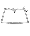
- FIG. 2 is a plan view of FIG.
- the windshield according to the present embodiment includes a glass plate 1 and a mask layer 2 laminated on the glass plate 1, and the mask layer 2 has an inter-vehicle distance such as a laser radar.
- a measuring unit 4 for measuring the distance is attached.
- each member will be described.
- the glass plate 1 can have various configurations.
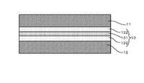
- the glass plate 1 can be composed of laminated glass having a plurality of glass plates, or can be composed of a single glass plate. In the case of using laminated glass, for example, it can be configured as shown in FIG. FIG. 3 is a sectional view of the laminated glass.
- this laminated glass includes an outer glass plate 11 and an inner glass plate 12, and a resin intermediate film 13 is disposed between the glass plates 11 and 12.
- the outer glass plate 11 and the inner glass plate 12 will be described.
- known glass plates can be used, and they can be formed of heat ray absorbing glass, general clear glass, green glass, or UV green glass.
- these glass plates 11 and 12 need to realize visible light transmittance in accordance with the safety standards of the country where the automobile is used. For example, the required solar radiation absorption rate can be ensured by the outer glass plate 11, and the visible light transmittance can be adjusted by the inner glass plate 12 so as to satisfy safety standards.
- a composition of clear glass, heat ray absorption glass, and soda-lime-type glass is shown.
- the composition of the heat-absorbing glass for example, based on the composition of the clear glass, the proportion of the total iron oxide in terms of Fe 2 O 3 (T-Fe 2 O 3) and 0.4 to 1.3 wt%, CeO
- the ratio of 2 is 0 to 2% by mass
- the ratio of TiO 2 is 0 to 0.5% by mass
- the glass skeleton components (mainly SiO 2 and Al 2 O 3 ) are T-Fe 2 O 3 , CeO.
- the composition can be reduced by an increase of 2 and TiO 2 .
- the thickness of the laminated glass according to the present embodiment is not particularly limited, but from the viewpoint of weight reduction, the total thickness of the outer glass plate 11 and the inner glass plate 12 is preferably 2.4 to 3.8 mm. The thickness is more preferably 2.6 to 3.4 mm, and particularly preferably 2.7 to 3.2 mm. Thus, since it is necessary to reduce the total thickness of the outer glass plate 11 and the inner glass plate 12 for weight reduction, the thickness of each glass plate is not particularly limited, For example, the thickness of the outer glass plate 11 and the inner glass plate 12 can be determined as follows.
- the outer glass plate 11 mainly needs durability and impact resistance against external obstacles. For example, when this laminated glass is used as a windshield of an automobile, the outer glass plate 11 has impact resistance performance against flying objects such as pebbles. is necessary. On the other hand, as the thickness is larger, the weight increases, which is not preferable. In this respect, the thickness of the outer glass plate 11 is preferably 1.8 to 2.3 mm, and more preferably 1.9 to 2.1 mm. Which thickness is adopted can be determined according to the application of the glass.
- the thickness of the inner glass plate 12 can be made equal to that of the outer glass plate 11, but for example, the thickness can be made smaller than that of the outer glass plate 11 in order to reduce the weight of the laminated glass. Specifically, considering the strength of the glass, it is preferably 0.6 to 2.0 mm, more preferably 0.8 to 1.6 mm, and 1.0 to 1.4 mm. Particularly preferred. Further, it is preferably 0.8 to 1.3 mm. Which thickness is used for the inner glass plate 12 can be determined according to the purpose of the glass.
- the shape of the outer side glass plate 11 and the inner side glass plate 12 which concerns on this embodiment is a curved shape.
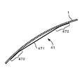
- the double amount is an amount indicating the bending of the glass plate. For example, as shown in FIG. 4, when a straight line L connecting the center of the upper side and the center of the lower side is set, the straight line L and the glass plate are set. The largest distance between the two is defined as a double amount D.
- FIG. 5 is a graph showing a relationship between a general frequency and sound transmission loss of a curved glass plate and a planar glass plate.
- the curved glass plate does not have a large difference in sound transmission loss (STL: Sound Transmission Loss) in the range of 30 to 38 mm in the amount of double, but is 4000 Hz compared with the planar glass plate.
- STL Sound Transmission Loss
- the sound transmission loss is reduced in the following frequency bands. Therefore, when producing a curved glass plate, the amount of double is better, but for example, when the amount of double exceeds 30 mm, the Young's modulus of the core layer of the intermediate film is set to 18 MPa (frequency) as will be described later. 100 Hz, temperature 20 ° C.) or less.
- a method for measuring the thickness when the glass plate is curved will be described.
- the measuring instrument is not particularly limited, and for example, a thickness gauge such as SM-112 manufactured by Teclock Co., Ltd. can be used.
- SM-112 manufactured by Teclock Co., Ltd.
- Teclock Co., Ltd. Teclock Co., Ltd.
- it is arranged so that the curved surface of the glass plate is placed on a flat surface, and the end of the glass plate is sandwiched by the thickness gauge and measured. Even when the glass plate is flat, it can be measured in the same manner as when the glass plate is curved.
- the intermediate film 13 is formed of at least one layer.
- the intermediate film 13 can be configured by three layers in which a soft core layer 131 is sandwiched between harder outer layers 132.
- it is not limited to this configuration, and may be formed of a plurality of layers including the core layer 131 and at least one outer layer 132 disposed on the outer glass plate 11 side.
- the intermediate film 13 may be disposed, or the intermediate film 13 may be configured such that the odd outer layer 132 is disposed on one side and the even outer layer 132 is disposed on the other side with the core layer 131 interposed therebetween.
- the outer layer 132 is provided on the outer glass plate 11 side as described above, but this is to improve the resistance to breakage against an external force from outside the vehicle or outside. Further, when the number of outer layers 132 is large, the sound insulation performance is also enhanced.
- the hardness thereof is not particularly limited.
- the material can be selected based on the Young's modulus. Specifically, it is preferably 1 to 20 MPa, more preferably 1 to 18 MPa, and particularly preferably 1 to 14 MPa at a frequency of 100 Hz and a temperature of 20 degrees. In such a range, it is possible to prevent the sound transmission loss from being lowered in a low frequency range of approximately 3500 Hz or less.
- Table 1 below shows the sound insulation performance of the laminated glass having an intermediate film composed of an outer glass plate and an inner glass plate made of clear glass, and an outer layer located on both sides of the core layer and the core layer. Show.
- the thickness of the outer glass plate is 2.0 mm
- the thickness of the inner glass plate is 1.3 mm
- the thickness of the intermediate film is 0.10 mm for the core layer and 0.33 mm for the outer layer, for a total of 0.76 mm.
- Table 1 below shows sound transmission loss when the frequency is between 1250 and 10,000 Hz.
- sound transmission loss is calculated when the Young's modulus (measured at a frequency of 100 Hz and a temperature of 20 ° C.) of the core layer of the interlayer film is 25 MPa, 12.5 MPa, and 6.25 MPa (a calculation method will be described later).
- the difference in sound transmission loss when the Young's modulus is 12.5 MPa and 6.25 MPa (unit: 0 in the following table, based on the case where the Young's modulus is 25 MPa) Indicates dB).
- the Young's modulus of the outer layer is 560 MPa, and tan ⁇ is 0.26 (temperature 20 ° C., frequency 100 Hz).
- Table 1 when the frequency is between 3150 and 5000 Hz, the sound transmission loss improves as the Young's modulus of the core layer of the intermediate film decreases from 25 MPa to 12.5 MPa and 6.25 MPa. I understand.
- frequency dispersion measurement can be performed with a strain amount of 0.05% using a solid viscoelasticity measuring device DMA 50 manufactured by Metravib.
- the Young's modulus is a value measured by the above method.
- the measurement when the frequency is 200 Hz or less uses an actual measurement value.
- a calculation value based on the actual measurement value is used. This calculated value is based on a master curve calculated by using the WLF method from the actually measured value.
- the Young's modulus of the outer layer 132 is preferably large in order to improve sound insulation performance in a high frequency region, as will be described later, and is 560 MPa or more, 600 MPa or more, 650 MPa or more, 700 MPa or more at a frequency of 100 Hz and a temperature of 20 degrees. It can be set to 750 MPa or more, 880 MPa or more, or 1300 MPa or more.
- the upper limit of the Young's modulus of the outer layer 132 is not particularly limited, but can be set from the viewpoint of workability, for example. For example, it is empirically known that when it becomes 1750 MPa or more, workability, particularly cutting becomes difficult.
- the Young's modulus of the outer layer on the outer glass plate 11 side is preferable to make the Young's modulus of the outer layer on the outer glass plate 11 side larger than the Young's modulus of the outer layer on the inner glass plate 12 side.
- tan ⁇ of the core layer 131 can be set to 0.1 to 0.9 at a frequency of 100 Hz and a temperature of 20 ° C.
- tan ⁇ is in the above range, the sound insulation performance is improved.
- Table 2 shows the sound insulation performance of laminated glass having an intermediate film composed of an outer glass plate and an inner glass plate made of clear glass, and an outer layer positioned on both sides of the core layer and the core layer. Show.
- the thickness of the outer glass plate is 2.0 mm
- the thickness of the inner glass plate is 1.3 mm
- the thickness of the intermediate film is 0.10 mm for the core layer and 0.33 mm for the outer layer, for a total of 0.76 mm.
- the Young's modulus of the core layer and the outer layer at this time is 12.5 MPa and 560 MPa, respectively (measured at a frequency of 100 Hz and a temperature of 20 ° C.).
- Table 2 below shows sound transmission loss when the frequency is between 1250 and 10000 Hz. Specifically, sound transmission loss is calculated when tan ⁇ (measured at a frequency of 100 Hz and a temperature of 20 ° C.) of the interlayer film is 0.8, 1.2, and 1.6 (a calculation method is described in an example described later). The difference in sound transmission loss when tan ⁇ is 1.2 and 1.6 (unit is dB), based on the case where tan ⁇ is 0.8 (in the following table, it is 0). ). Note that tan ⁇ of the outer layer is 0.26. According to Table 2, when the frequency is between 5000 and 10,000 Hz, the sound transmission loss is improved as the tan ⁇ of the intermediate film increases from 0.8 to 1.2, 1.6. .
- each of the layers 131 and 132 is not particularly limited, but it is necessary that the material has at least a Young's modulus in the above range.
- these layers 131 and 132 can be formed of a resin material.
- the outer layer 132 can be made of polyvinyl butyral resin (PVB). Polyvinyl butyral resin is preferable because it is excellent in adhesiveness and penetration resistance with each glass plate.
- the core layer 131 can be composed of an ethylene vinyl acetate resin (EVA) or a polyvinyl acetal resin that is softer than the polyvinyl butyral resin that constitutes the outer layer 132.
- the hardness of the polyvinyl acetal resin is controlled by (a) the degree of polymerization of the starting polyvinyl alcohol, (b) the degree of acetalization, (c) the type of plasticizer, (d) the addition ratio of the plasticizer, etc. Can do. Therefore, by appropriately adjusting at least one selected from these conditions, a hard polyvinyl butyral resin used for the outer layer 132 and a soft polyvinyl butyral resin used for the core layer 131 even if the same polyvinyl butyral resin is used. Can be made separately.
- the hardness of the polyvinyl acetal resin can also be controlled by the type of aldehyde used for acetalization, coacetalization with a plurality of aldehydes, or pure acetalization with a single aldehyde. Although it cannot generally be said, the polyvinyl acetal resin obtained by using an aldehyde having a large number of carbon atoms tends to be softer.
- the core layer 131 has an aldehyde having 5 or more carbon atoms (for example, n-hexylaldehyde, 2-ethylbutyraldehyde, n-heptylaldehyde, n-octylaldehyde) and a polyvinyl acetal resin obtained by acetalization with polyvinyl alcohol can be used.
- a predetermined Young's modulus it is not limited to the said resin.
- the total thickness of the intermediate film 13 is not particularly limited, but is preferably 0.3 to 6.0 mm, more preferably 0.5 to 4.0 mm, and 0.6 to 2.0 mm. It is particularly preferred.
- the thickness of the core layer 131 is preferably 0.1 to 2.0 mm, and more preferably 0.1 to 0.6 mm.
- the thickness of each outer layer 132 is preferably larger than the thickness of the core layer 131. Specifically, the thickness is preferably 0.1 to 2.0 mm, and preferably 0.1 to 1.0 mm. Is more preferable.
- the total thickness of the intermediate film 13 can be made constant, and the thickness of the core layer 131 can be adjusted therein.
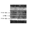
- the thickness of the core layer 131 and the outer layer 132 can be measured as follows, for example. First, the cross section of the laminated glass is enlarged and displayed by 175 times using a microscope (for example, VH-5500 manufactured by Keyence Corporation). And the thickness of the core layer 131 and the outer layer 132 is specified visually, and this is measured. At this time, in order to eliminate visual variation, the number of measurements is set to 5 times, and the average value is defined as the thickness of the core layer 131 and the outer layer 132. For example, an enlarged photograph of a laminated glass as shown in FIG. 7 is taken, and the core layer and the outer layer 132 are specified in this and the thickness is measured.
- the thickness of the core layer 131 and the outer layer 132 of the intermediate film 13 does not need to be constant over the entire surface, and can be a wedge shape for laminated glass used for a head-up display, for example.
- the thickness of the core layer 131 and the outer layer 132 of the intermediate film 13 is measured at the position where the thickness is the smallest, that is, the lowermost side portion of the laminated glass.
- the intermediate film 3 is wedge-shaped, the outer glass plate and the inner glass plate are not arranged in parallel, but such arrangement is also included in the glass plate in the present invention.
- the arrangement of the outer glass plate 11 and the inner glass plate 12 when the intermediate film 13 using the core layer 131 and the outer layer 132 whose thickness is increased at a change rate of 3 mm or less per 1 m is used. including.
- the method for producing the intermediate film 13 is not particularly limited.
- the resin component such as the polyvinyl acetal resin described above, a plasticizer, and other additives as necessary are blended and kneaded uniformly, and then each layer is collectively And a method of laminating two or more resin films prepared by this method by a pressing method, a laminating method or the like.
- the resin film before lamination used in a method of laminating by a press method, a laminating method or the like may have a single layer structure or a multilayer structure.
- the intermediate film 13 can be formed of a single layer in addition to the above-described plural layers.
- the windshield according to the present embodiment is used for a vehicle front safety system using a measurement unit such as a laser radar or a camera.
- a measurement unit such as a laser radar or a camera.
- the vehicle ahead is irradiated with infrared rays to measure the speed and distance between the vehicles ahead. Therefore, the laminated glass (or one glass plate) is required to achieve a predetermined range of infrared transmittance.
- transmittance for example, when a general sensor is used for laser radar, it is 20% to 80%, preferably 20% to 60% with respect to light (infrared rays) having a wavelength of 850 to 950 nm.
- the measuring method of the transmittance can be UV3100 (manufactured by Shimadzu Corporation) as a measuring device according to JIS R3106. Specifically, the transmission of light in one direction irradiated at an angle of 90 degrees with respect to the surface of the laminated glass is measured.
- some safety systems such as those described above measure the speed and distance between vehicles ahead using an infrared camera without using a laser radar.
- a camera commonly used for laser radar is used.
- it is considered useful to be 30% or more and 80% or less, preferably 40% or more and 60% or less, with respect to light (infrared rays) having a wavelength of 700 to 800 nm.
- the measuring method of the transmittance follows ISO9050.
- a mask layer 2 as shown in FIG. 8 is formed on the glass plate 1 according to the present embodiment.
- the mask layer 2 is laminated
- the glass plate is formed of a single glass plate, the mask layer 2 can be laminated on the inner surface of the vehicle.
- the glass plate is formed of laminated glass as shown in FIG. 3, the vehicle inner surface of the outer glass plate 11, the vehicle outer surface of the inner glass plate 12, and the vehicle inner surface of the inner glass plate 12. It can be laminated to at least one of the surfaces.
- the portion where the mask layer 2 is laminated is formed. Since the curvature of both the glass plates 11 and 12 corresponds, it is preferable.
- the mask layer 2 is a dark region for preventing the outside from being seen from the outside, such as application of an adhesive for attaching the glass plate 1 to the vehicle body, and is formed on the outer peripheral edge of the glass plate 1.
- a peripheral mask layer 21 and a center mask layer 22 extending downward from the center of the upper edge of the glass plate 1 in the peripheral mask layer 21 are provided.
- the measurement unit 4 described above is attached to the center mask layer 22. As will be described later, the measurement unit 4 only needs to be arranged so that light emitted from the sensor 5 passes through the center of the opening and can receive reflected light from the preceding vehicle and the obstacle.
- These mask layers 2 can be formed of various materials, but are not particularly limited as long as they can shield the field of view from the outside of the vehicle. For example, dark ceramic such as black is applied to the glass plate 1. Can be formed.
- the center mask layer 22 is formed in a rectangular shape extending in the vertical direction, and two openings arranged in the vertical direction, that is, an upper opening 231 and a lower opening 232 are formed. Both the upper opening 231 and the lower opening 232 are formed in a trapezoidal shape, but the width of the lower opening 232 in the left-right direction is about half that of the upper opening 231. However, the length in the vertical direction is substantially the same.
- the size of the opening is not particularly limited.
- the upper opening 231 can be about 58 mm in length and about 58 mm in width
- the lower opening 232 can be about 52 mm in length and about 27 mm in width.
- the center mask layer 22 is divided into three regions, an upper region 221 above the upper opening 231, a lower region 222 including both openings 231 and 232 below the upper region 221, and the side of the lower region 222. It is composed of small rectangular side regions 223 formed in the part.
- the upper region 221 is formed of one layer by a first ceramic layer 241 made of black ceramic.
- the lower region 222 is formed of three layers including the first ceramic layer 241, the silver layer 242, and the second ceramic layer 243 that are stacked from the inner surface of the glass plate 1.
- the silver layer 242 is made of silver, and the second ceramic layer 243 is made of the same material as the first ceramic layer 241.
- region 223 is formed with two layers, the 1st ceramic layer 241 and the silver layer 242, which are laminated
- the lowermost first ceramic layer 241 is common in each region, and the second silver layer 242 is common in the lower region 222 and the side region 223.
- the thickness of each ceramic layer 241 and 243 can be set to 10 to 20 ⁇ m, for example.
- the bracket of the measurement unit 4 is adhered to the center mask layer 22 formed on the inner surface of the inner glass plate 12 with an adhesive, this also ensures the adhesion.
- Such a thickness is preferred. This is because, for example, the urethane / silicone adhesive may be deteriorated by ultraviolet rays or the like.
- the peripheral mask layer 21 and the center mask layer 22 can be formed as follows, for example. First, the 1st ceramic layer 241 is apply
- the ceramic layers 241 and 243 can be formed of various materials.
- the ceramic layers 241 and 243 can have the following composition. * 1, Main component: Copper oxide, Chromium oxide, Iron oxide and Manganese oxide * 2, Main component: Bismuth borosilicate, Zinc borosilicate
- the silver layer 242 is not particularly limited, and for example, the following composition can be used. * 1, Main component: Bismuth borosilicate, Zinc borosilicate
- polyester screen 355 mesh
- coat thickness 20 ⁇ m
- tension 20 Nm
- squeegee hardness 80 degrees
- mounting angle 75 °
- printing speed 300 mm / s
- the ceramic layer and the silver layer can be formed by drying at 150 ° C. for 10 minutes.
- laminating stacking the 1st ceramic layer 241, the silver layer 242, and the 2nd ceramic layer 243 in this order, what is necessary is just to repeat screen printing and drying mentioned above.
- a heating furnace 901 and a molding device 902 are arranged in this order from upstream to downstream.
- a roller conveyor 903 is arranged from the heating furnace 901 to the molding apparatus 902 and the downstream side thereof, and the glass plate 10 to be processed is conveyed by the roller conveyor 903.
- the glass plate 10 is formed in a flat plate shape before being carried into the heating furnace 901. After the mask layer 2 described above is laminated on the glass plate 10, the glass plate 10 is carried into the heating furnace 901.
- the heating furnace 901 can have various configurations, but can be an electric heating furnace, for example.
- the heating furnace 901 includes a rectangular tube-shaped furnace main body whose upstream and downstream ends are open, and a roller conveyor 903 is disposed in the interior from upstream to downstream.
- Heaters (not shown) are disposed on the upper surface, the lower surface, and the pair of side surfaces of the inner wall surface of the furnace body, respectively, and the temperature at which the glass plate 10 passing through the heating furnace 901 can be formed, for example, the softening point of glass. Heat to near.
- the forming apparatus 902 is configured to press a glass plate with an upper die 921 and a lower die 922 to form a predetermined shape.
- the upper die 921 has a downwardly convex curved shape so as to cover the entire upper surface of the glass plate 10, and is configured to be movable up and down.
- the lower die 922 is formed in a frame shape corresponding to the peripheral edge of the glass plate 10, and the upper surface thereof has a curved shape so as to correspond to the upper die 921. With this configuration, the glass plate 10 is press-formed between the upper die 921 and the lower die 922, and formed into a final curved shape.
- a roller conveyor 903 is disposed in the frame of the lower mold 922, and the roller conveyor 903 can move up and down so as to pass through the frame of the lower mold 922. And although illustration is abbreviate
- the roller conveyor 903 as described above is a known one, and a plurality of rollers 931 whose both ends are rotatably supported are arranged at predetermined intervals.
- a sprocket can be attached to the end of each roller 931, and a chain can be wound around each sprocket to drive it.
- the conveyance speed of the glass plate 10 can also be adjusted by adjusting the rotational speed of each roller 931.
- molding apparatus 902 shape
- the intermediate film 13 is subsequently sandwiched between the outer glass plate 11 and the inner glass plate 12, put into a rubber bag, and sucked under reduced pressure. While pre-adhering at about 70-110 ° C. Other pre-adhesion methods are possible.
- the intermediate film 13 is sandwiched between the outer glass plate 11 and the inner glass plate 12 and heated at 45 to 65 ° C. in an oven. Subsequently, this laminated glass is pressed by a roll at 0.45 to 0.55 MPa. Next, the laminated glass is again heated at 80 to 105 ° C. in an oven and then pressed again with a roll at 0.45 to 0.55 MPa. Thus, preliminary adhesion is completed.
- the shielding film 70 is stuck before the preliminary bonding.
- the laminated glass that has been pre-adhered is subjected to main bonding by an autoclave at, for example, 8 to 15 atm and 100 to 150 ° C.
- the main bonding can be performed under the conditions of 14 atm and 145 ° C.
- the manufacturing method of a glass plate is also the same. After forming a mask layer on the inner surface of the glass plate, heating is performed, and thereafter, the glass plate is formed into a curved shape.
- the mounting angle of the laminated glass is preferably 45 degrees or less from the vertical.
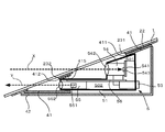
- FIG. 12 is a cross-sectional view showing a schematic configuration of the measurement unit 4 attached to the glass plate, and FIG.
- the measurement unit 4 includes a bracket (attachment member) 41 fixed to the inner surface of the glass plate 1, a sensor (information acquisition device) 5 supported by the bracket 41, and the bracket 41 and the sensor 5. Is covered with a cover 42 that covers from the inside of the vehicle.
- the bracket 41 is formed in a rectangular shape, and an adhesive 401 and a double-sided tape 402 are applied to the center mask layer 22 formed on the inner surface of the inner glass plate 12 as described above. Fixed.
- the bracket 41 is formed with two openings arranged vertically and partitioned by the partition portion 415, that is, a first opening 411 and a second opening 412, and a large first opening 411 formed on the upper side.
- the sensor 5 is attached to.
- a trapezoidal concave portion 414 is formed below the second opening 412 when viewed from the outside of the vehicle.
- the recess 414 is inclined so that the upper end is deepest and becomes shallower toward the lower end, and a second opening 412 is formed at the upper end.
- support portions 413 that support the sensor 5 are attached to both sides of the first opening 411 on the inner surface of the bracket 41, and the sensor 5 includes both support portions. It is fixed between 413.
- An irradiation lens 552 is attached to the tip of the fixed sensor 5 (lower end in FIG. 13), as will be described later, and this irradiation lens 552 faces the outside through the second opening 412 and the recess 414. It has become.
- the concave portion 414 forms a gap with the glass plate and serves as a path for light emitted from the second opening 412.
- the light receiving lens 542 faces the outside through the first opening 411.
- the upper side, the right side, the lower side, and the left side of the frame of the bracket 41 shown in FIG. 13 correspond to the first side, the second side, the third side, and the fourth side of the present invention.
- the recessed part 414 is integrally provided in the bracket 41, the location which comprises the recessed part 414 in the bracket 41 corresponds to the channel
- the outer surface of the bracket 41 is a surface fixed to the center mask layer 22 (corresponding to the fixing portion of the present invention, hereinafter referred to as a fixing portion),
- a bead-shaped adhesive 401 is applied to the position corresponding to the support portion 413 and the upper periphery of the first opening 411.
- a known double-sided tape 402 is attached to the upper and lower sides of the adhesive 401 at a position corresponding to the support portion 413.
- double-sided tape 402 is also attached to both sides of the partition portion 415 and the recess 414.
- the portions to which the double-faced tape 402 and the adhesive 401 are applied and fixed to the mask layer 22 are all fixed portions.
- Various adhesives can be employed, and for example, a urethane resin adhesive, an epoxy resin adhesive, or the like can be used.
- the epoxy resin adhesive is advantageous because it is difficult to flow because of its high viscosity.
- the cover 42 is attached from the vehicle inside.
- the sensor 5 and the bracket 41 are not visible from the inside of the vehicle.
- the sensor 5 is accommodated in the space surrounded by the bracket 41, the cover 42, and the glass plate 1. Since the center mask layer 22 is formed, the measurement unit 4 cannot be seen from the outside of the vehicle except for the upper opening 231 and the lower opening 232.
- the sensor 5 includes a housing 51 having a triangular shape in a side view, and the inside of the housing 51 is partitioned into an upper space 501 and a lower space 502.
- a connector 53 is attached to the back side of the casing 51 and is used for connection to an external device.
- a first support portion 54 is disposed in the upper space 501, and a first control board 541 and a light receiving lens 542 are disposed in the first support portion 54 from the rear to the front.
- a light receiving element 543 is mounted on the first control board 541 so as to receive laser light that has passed through the light receiving lens 542 and convert it into an electrical signal. This electric signal is amplified by the first control board 541 and transmitted to the second control board 56 described later.
- the light receiving lens 542 is arranged so as to face the outside from the first opening 411 of the bracket 41 through the upper opening 231 of the center mask layer 22.
- the senor 5 is supported by the bracket 41 so that the passage path of the light received by the light receiving element 543 passes near the center X of the upper opening 231 (see FIG. 12).
- reflected light from multiple directions reflected from the preceding vehicle or obstacle passes near the center of the upper opening 231, and the light receiving element 543 receives the reflected light.
- the second support portion 55 is disposed in the lower space 502, and the laser light emitting element 551 and the irradiation lens 552 are supported on the second support portion 55 in this order from the rear to the front.
- the laser light emitting element 551 transmits laser light having a wavelength range of 850 nm to 950 nm, such as a laser diode
- the irradiation lens 552 is a lens that shapes the laser light from the laser light emitting element 551 into a predetermined beam shape. It is.
- the irradiation lens 552 is disposed so as to face the outside from the housing 51 through the second opening 412 of the bracket 41 and the lower opening 232 of the center mask layer 22.
- the sensor 5 is supported by the bracket 41 so that the passage path of the laser light emitted from the laser light emitting element 551 passes through the vicinity Y of the center of the lower opening 232 (see FIG. 12).
- a second control board 56 is disposed on the upper surface of the second support portion 55, and drives the laser light emitting element 551, processes an electric signal transmitted from the first control board 541, and the like.
- the first control board 541 transmits a pulse of laser light from the laser light emitting element 551. Then, the distance between the preceding vehicle or the obstacle and the own vehicle is calculated based on the time until the reflected light reflected by the preceding vehicle or the obstacle is received by the light receiving element 543. The calculated distance is transmitted to an external device via the connector 53 and used for brake control and the like.
- the senor 5 is supported by the support portion 413 in the bracket 41, and the position corresponding to the support portion 413 is fixed to the center mask layer 22 by the adhesive 401. Therefore, the portion of the bracket 41 to which the sensor 5 is attached is firmly fixed to the mask layer 22, so that displacement and vibration of the sensor 5 can be prevented. Further, since the double-sided tape 402 is attached in the vicinity of the adhesive 401, the double-sided tape 402 can be used as a fixing material for temporary fixing until the adhesive 401 is dried.
- the thickness of the adhesive 401 can be matched to the thickness of the double-sided tape 402. Therefore, it is possible to prevent the adhesive 401 from being excessively crushed and protruding from the bracket 41. Therefore, if the application amount of the adhesive is adjusted, it is possible to reliably prevent the adhesive from protruding from the fixed portion. Furthermore, by using the double-sided tape 402, since there is no fluidity like an adhesive, it does not protrude even if the width of the bracket 41 is small. Therefore, it is possible to prevent the appearance from deteriorating due to the protrusion. It can also be used for narrow regions.
- the adhesive 401 is used as the main fixing material and the double-sided tape 402 is used as the temporary fixing material. However, other fixing materials can be used. It can also be used as a material.
- the vicinity of the position corresponding to the support portion 413 may be fixed to the center mask layer 22 with the adhesive 401 or the double-sided tape 402.
- an adhesive 401 and a double-sided tape 402 are also provided on both sides of the upper periphery of the first opening 411, the partition portion 415, and the recess 414, and these are used as a light shielding member.
- the reason is as follows. That is, since the glass plate 1 according to the present embodiment is curved, a gap may be generated between the bracket 41 and the glass plate 1. If light enters the first opening 411 or the second opening 412 from the outside through such a gap, the light emitted from the sensor 5 or the light received by the sensor 5 from the outside may be affected. There is.
- the adhesive 401 and the double-sided tape 402 are also arranged on the upper peripheral edge of the first opening 411, the partition portion 415, and the concave portion 414, thereby shielding the periphery of the first opening 411.
- the periphery of the recess 414 that is, the periphery of the second opening 412 is also shielded.
- the concave portion 414 serves as a light path formed between the opening 232 of the center mask layer 22 and the sensor 5, it is particularly preferable to shield the periphery thereof.
- the irradiated laser light is reflected by the glass plate, and the reflected light may leak out from the gap. Then, the leaked laser light may be received as stray light through the first opening 414, which causes malfunction. For this reason, it is preferable to provide a light shielding member for filling the gap in the vicinity of the recess 414 and the second opening 412. Further, regarding the upper side that is the upper part of the first opening 411, sunlight may be incident from above, which may cause malfunction of the sensor 5. Therefore, a light shielding member may be provided also in this part. preferable. In addition, although it is not necessary to arrange
- the adhesive 401 and the double-sided tape 402 are mainly elastically deformable, they can be deformed according to the size of the gap, and the gap can be effectively filled. As a result, light from the outside to each of the openings 411 and 412 is blocked, and the sensor 5 can be prevented from malfunctioning.
- the double-sided tape is generally harder to deform than the adhesive, but for this, for example, a thick double-sided tape may be used or a plurality of double-sided tapes may be laminated.
- the double-sided tape 402 is advantageous in that it can be used even in a narrow region as described above and has no fluidity.
- the adhesive may have a higher fixing strength.
- the position where the light shielding member is attached is not particularly limited, and it is preferable that the light shielding member is attached so as to surround substantially the entire circumference of the bracket 41.
- the light shielding member may not necessarily be the entire circumference, and is generally between the bracket 41 and the mask layer 2. It is sufficient that no gap is formed.
- the recess 414 is a light path, it is necessary to attach a light shielding member in the vicinity thereof, but it is not necessary to provide the entire periphery of the recess 414 for the above reason.
- the light shielding member may be composed of an elastically deformable sponge, rubber, etc. in addition to the above-mentioned adhesive and double-sided tape.
- the light shielding member when the light shielding member is made of a material having low elasticity, it can be adopted as the light shielding member of the present invention.
- the light shielding member is made of a material having strong elasticity, and an adhesive or double-sided tape When used together with it, problems may arise.
- an adhesive or a double-sided tape is provided in the vicinity of a highly elastic light shielding member (hereinafter referred to as an elastic light shielding member)
- an elastic light shielding member a highly elastic light shielding member
- a force acts in a direction in which the bracket 41 is separated from the glass plate 1 or the mask layer by the elastic force of the elastic light shielding member.
- the nearby adhesive or double-sided tape is peeled off. Therefore, it is preferable to use a light shielding member having such an elastic force that other adhesives and double-sided tape are not peeled off.
- the mask layer 2 is laminated on the glass plate 1 by screen printing or the like. Thereafter, the glass plate 1 is heated and molded. At this time, since the mask layer 2 is a dark color such as black, the amount of heat absorbed in the glass plate 1 is larger than that of a region where the mask layer 2 is not formed, for example, the upper opening 231 and the lower opening 232. Become. And since the thermal expansion coefficient differs between the mask layer 2 and the glass plate 1, the compressive stress and tensile stress at the time of shaping
- the glass plate 1 Due to the difference in curvature of the surface, the glass plate 1 is distorted in the vicinity of the boundary between the upper opening 231 and the lower opening 232 (hereinafter, a region where the distortion occurs is referred to as a strain region).
- a region where the distortion occurs is referred to as a strain region.
- the distortion is more pronounced in the laminated glass having different thicknesses because it bends more than the outer glass plate 11 near the boundary of the inner glass plate 12. become. For this reason, when the laser light is irradiated and received, if the laser light passes through the strain region, the light may be refracted due to the distortion, or the laser light may not be irradiated accurately or received.
- the sensor 5 is supported by the bracket 41 so that the light path passes through the vicinity of the center of the upper opening 231 and the lower opening 232 of the mask layer 22. It is possible to prevent light from passing through a region where such distortion occurs.
- the bracket 41 may not necessarily pass through the vicinity of the center, and the bracket 41 has a light passage path X in light irradiation and / or light reception of at least 4 mm from the periphery of the openings 231 and 232 of the mask layer 2, preferably The sensor 5 may be attached so as to be 6 mm away.
- the horizontal axis represents the length in the surface direction of the glass plate
- the vertical axis represents the lens power (mili diopter: reciprocal of focal length).
- the method for measuring the lens power is as follows. First, light is projected onto a glass plate in a dark room, and a shadow is formed on the screen behind the glass plate. At this time, if there is a convex lens on the glass plate, the light is condensed and the shadow on the screen becomes bright. On the other hand, it becomes dark when there is a concave lens on the glass plate.
- the lens power of the glass plate can be obtained by arranging the target glass plate and measuring the brightness on the screen over the entire surface of the glass.
- the example of the sensor 5 for measuring the distance between vehicles was shown, it is not limited to this, The distance between vehicles can be measured by irradiating light and receiving the reflected light. If there is, it is not particularly limited.
- the senor 5 for measuring the inter-vehicle distance is used as the information acquisition device of the present invention, but the present invention is not limited to this, and various information acquisition devices can be used. That is, there is no particular limitation as long as light is emitted and / or received in order to acquire information from outside the vehicle.
- a visible light and / or infrared camera for measuring the distance between vehicles a light receiving device for receiving a signal from outside the vehicle such as an optical beacon, a camera using visible light and / or infrared light that reads a white line of a road in an image, etc.
- the present invention can be applied to various devices.
- the center mask layer has one opening.
- a plurality of openings can be provided depending on the type of light.
- the information acquisition device may or may not be in contact with the glass.
- the bracket 41 supports the camera so that the field of view of the camera (passage range of visible light or infrared light) is disposed inside the inner edge of the opening of the center mask layer 22.
- the form of the bracket 41 is not limited to that described above, and various forms are possible.
- one opening may be provided, and when a plurality of information acquisition devices are used, there may be three or more openings.
- the concave portion 414 serves as a light passage formed between the opening of the mask layer 2 and the sensor 5, and the concave portion only needs to communicate with any one of the openings of the bracket. It may be provided at any position.
- the shape of the recess may not be formed in an inclined shape, and the shape is not particularly limited as long as it becomes a light path.
- the mask layer 2 has a three-layer structure as described above, but is not limited to this. That is, in the above embodiment, the silver layer 242 is provided in order to shield electromagnetic waves, but other materials such as a method of providing a single layer in which silver and a ceramic layer are mixed, or an electromagnetic wave can be shielded. Copper, nickel, etc. may be laminated. In addition, the silver layer 242 is sandwiched between ceramic layers so that the silver layer 242 cannot be seen from the outside. However, in addition to covering with the ceramic layer, a member such as the cover described above can also be used. Further, it is not always necessary to provide an electromagnetic wave shielding layer, and at least a layer that cannot be seen from the outside may be formed. Further, a silver layer can be applied to hide the above-described region where distortion occurs.
- the mask layer 2 can be other than black, and is not particularly limited as long as it is a dark color such as brown, gray, or dark blue that blocks the field of view from the outside of the vehicle and prevents the inside of the vehicle from being seen.
- a shielding film can be attached instead of ceramic.
- Such a film can be, for example, a dark resin film. Specifically, it can be formed of polyvinyl chloride, polyurethane, polyethylene, polyethylene terephthalate or the like, and is attached to the glass plate 1 with an adhesive.
- the adhesive is not particularly limited, but an acrylic adhesive or the like can be used.
- shielding film 70 for example, ABF Film, FTW9953J Film, Black Film, and Black Out Film (for example, FRA-3045J) manufactured by Sumitomo 3M may be used.
- the shielding film 70 may be attached so as to overlap the mask layer 22.
- the said embodiment demonstrated the example which fixed the bracket 41 with respect to the mask layer 2 when the mask layer 2 is formed in the inner side (inner surface of the inner side glass plate 12) of a glass plate, for example, a laminated glass
- the bracket 41 is positioned at the inner surface of the inner glass plate 12 where the mask layer 2 is formed. And are fixed at corresponding positions.
- the mask layer 2 can be composed of ceramic and film.
- the peripheral mask layer 21 may be formed of ceramic
- the center mask layer 22 may be formed of a film.
- the main fixing material and the temporary fixing material for fixing the bracket 41 to the mask layer 2 also serve as a light shielding member, but this may be made separate.
- a permanent fixing material and a temporary fixing material may be provided at a position unrelated to light shielding and separated from a light shielding member for light shielding.
- the light-shielding member, the main fixing material, and the temporary fixing material can be appropriately selected from various materials such as adhesives and double-sided tapes. There is no distinction between materials and temporary fixing materials.
- the above-described measurement unit 4 is mounted near the upper center of the windshield, and a rear view mirror is generally mounted at this position.
- the method of attaching the rear view mirror is not particularly limited, but can be attached adjacent to the measurement unit 4 as shown in FIGS. 16 and 17.
- the rear view mirror 481 is fixed to the mask layer 2 via a rod-like base member 482. That is, one end of the rod-shaped base member 482 is fixed to the mask layer 2, and the rear view mirror 481 is fixed to the other end of the base member 482. At this time, the rear view mirror 481 is fixed to the base member 482 so that the angle can be changed.
- the rear view mirror is a well-known one, and includes a rectangular mirror support portion and a rectangular mirror fitted on one surface thereof. Then, the other end portion of the base member 482 is attached to the other surface of the mirror support portion.
- the base member 482 and the bracket 41 of the measurement unit 4 are fixed to the mask layer 2 by the same fixing material. That is, it is fixed with an adhesive or double-sided tape of the same material.
- Various adhesives can be used.
- a urethane resin adhesive or an epoxy resin adhesive can be used.
- the use of an epoxy resin adhesive is advantageous because an adhesive strength can be obtained with a small amount of application compared to a urethane resin adhesive.
- the base member 482 since the rear view mirror 481 often changes its angle manually, the base member 482 needs to be firmly bonded to the mask layer 2. From this point, the base member 482 is masked with an epoxy resin adhesive. It is preferably fixed to the layer 2.
- the epoxy resin adhesive has a higher viscosity than the urethane resin adhesive, it is difficult to flow after application, and can be prevented from protruding from the bracket 41 or the base member 482.
- the adhesive may interfere with the light path in the sensor 5, and in this case, there is a problem that information cannot be accurately recognized. is there.
- the bracket is fixed to the glass plate with an epoxy resin adhesive, the applied adhesive hardly spreads and the protrusion from the bracket 41 is prevented. As a result, information can be accurately recognized.
- the adhesive is applied to one end of the base member and the bracket by an application device.
- the adhesive can be continuously applied to the base member 482 and the bracket 41 by using the same adhesive. Therefore, it is efficient.
- the base member 482 and the bracket 41 are arranged side by side on a pallet in a production line, and the adhesive is continuously applied to these by a coating apparatus. Thereafter, the base member 482 and the bracket 41 to which the adhesive is applied are fixed to a corresponding portion of the glass plate manually or by a machine.
- double-sided tape can be used instead of adhesive. If a double-sided tape is used, no protrusion like an adhesive occurs, so that it is suitable for fixing a portion having a small area to the mask layer. Moreover, since the time to dry like an adhesive agent is unnecessary, the operation
- the base member 482 may be attached by other methods than those described above.
- the base member 482 can be fixed inside the bracket 41 as shown in FIG. That is, after fixing the bracket 41 to the mask layer 2, the base member 482 is fixed to the mask layer 2 within the frame of the bracket 41 (for example, the first opening).
- the bracket 41 is closed with the cover 42.
- the cover 42 is formed with a through hole or notch through which the base member 482 passes.
- a bracket is not limited to the said embodiment, A various aspect is possible. That is, the bracket 41 can take various modes depending on the number and form of the sensors 5 and can be appropriately changed in size, shape, number of openings, number of support portions, and the like. Similarly, the position, size, and number of the recesses 414 can be changed. Further, the positions of the adhesive and the double-sided tape are not particularly limited.
- the configuration, position, and number of the support portions 413 are not particularly limited, and may be, for example, as long as the sensor 5 can be supported.
- the light irradiation path and the light receiving path from the sensor 5 pass through a position at least 4 mm away from the periphery of the openings 231 and 232 of the mask layer 2 as described above, as shown in FIG. It is particularly preferable to pass near the center.
- the flat bracket 41 can be attached to the glass plate 1 as follows. That is, as shown in FIG. 19, the rigidity of a part of the fixing part of the bracket 41 fixed to the glass plate 1 (mask layer 2) is lowered, and at least a part of the fixing part is bent or bent. That's fine. For example, a first region 471 having high rigidity and a second region 472 having low rigidity are formed in the fixing portion of the bracket 41. Since the second region 472 is easy to bend or bend, the fixing portion of the bracket 41 can be reliably fixed to the curve of the glass plate 1. Thereby, the mounting accuracy of the bracket 41 is improved, and the bracket 41 can be firmly fixed to the mask layer 2.
- a support portion 413 for attaching the sensor 5 can be attached at a position corresponding to the first region 471. Thereby, since the sensor 5 is fixed to the first region 471 having high rigidity, the sensor 5 becomes difficult to move or move together with the bracket 41, and the mounting accuracy of the sensor 5 is improved.
- FIG. 19 shows that a large gap is generated between the first region 471 and the glass plate 1, but it is assumed that such a gap does not actually occur or has occurred. Therefore, the gap may be filled with the above-described adhesive 401, double-sided tape 402, or the like, and thereby the first region 471 is firmly fixed.
- the second region 472 can be formed by various methods. That is, it is sufficient if the rigidity can be made lower than that of the first region 471. For example, the width can be reduced or the thickness can be reduced as shown in FIG. Alternatively, as shown in FIG. 20B, the second region 472 can be formed of a material with low rigidity, for example, an elastically deformable material. In addition, the second region 472 can be molded into a curved shape in advance so as to follow the curvature of the glass plate, in addition to reducing the rigidity.
- the bracket 41 there are various methods for attaching the bracket 41 to the mask layer 2 (or glass plate).
- at least one of the first region 471 and the second region 472 may be fixed to the mask layer 2.
- the second region 472 can be elastically deformed, only the second region 472 may be fixed along the curvature of the mask layer 2 or the first region 471 may be fixed.
- the glass plate can also be formed as follows. First, a flat laminated glass 10 in which the inner glass plate 12 and the outer glass plate 11 are overlapped is prepared. In addition, the mask layer is laminated
- FIG. 22 is a plan view of the mold
- FIG. 23 is a partial cross-sectional view of FIG. 22 showing a state where a laminated glass is placed.
- the mold 800 includes a frame-shaped mold body 810 that substantially matches the outer shape of the laminated glass 10. Since this mold body 810 is formed in a frame shape, it has an internal space 820 that penetrates in the vertical direction. And the peripheral part of the flat laminated glass 10 is mounted in the upper surface of this type
- the shielding board 840 for shielding heat may be arrange
- the shielding plate 840 extends to a position covering the bent portion b, but this suppresses heat reaching the bent portion b from the heater 830, and the bent portion b is excessively increased. Prevents bending.
- the heater can be provided not only below the mold 800 but also above it.
- the laminated glass 10 passes through a heating furnace 802 as shown in FIG. 21 while being supported by such a mold.
- the laminated glass 10 When heated to near the softening point temperature in the heating furnace 802, the laminated glass 10 is bent downward on the inner side from the peripheral edge by its own weight, and is formed into a curved surface.
- the laminated glass 10 is carried into the slow cooling furnace 803 from the heating furnace 802, and a slow cooling process is performed. Thereafter, the laminated glass 10 is taken out of the slow cooling furnace 803 and allowed to cool.
- the inner glass plate 12 and the outer glass plate 11 are formed in a curved shape, the intermediate film is sandwiched between them, and the above-described preliminary bonding and main bonding are performed. Thereby, a laminated glass is completed.
- a laminated glass is shape
- the bracket 41 is attached while avoiding a portion having a particularly large distortion, so that the attachment accuracy of the bracket 41 can be improved and the attachment strength can be improved.
- molding can also be performed with respect to one glass plate instead of a laminated glass.
- the opening formed in the mask layer 2 is a closed opening whose entire circumference is surrounded by the mask layer 2 in each of the above embodiments, but the opening in the present invention does not necessarily have to be closed. Some may be opened. For example, as shown in FIG. 24, an opening 232 that opens downward may be used. Further, the position is not limited to the lower side, and any position around the opening may be opened.
- the bracket 41 is directly fixed to the glass plate 1 instead of the mask layer 2 in the open portion of the opening 232. Therefore, the double-sided tape for fixing the bracket 41 and the glass plate 1 and the light shielding member of adhesive can be visually recognized from the outside. Therefore, the light shielding member for directly fixing the bracket 41 and the glass plate 1 is preferably a double-sided tape that is difficult to visually recognize from the outside. This is because when an adhesive is used, it is crushed between the bracket 41 and the glass plate 1 and looks bad.
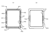
- FIG. 25 is a view of the bracket as viewed from the outside of the vehicle (a), a view of the bracket as viewed from the inside of the vehicle (b), and FIG. 26 is a view of the sensor as viewed from the outside of the vehicle.
- the bracket 700 is not formed with a recess as shown in FIG.
- the bracket 700 is formed in a rectangular frame shape having a mounting opening 701 in which the sensor 500 is disposed.
- the bracket 700 is disposed on a rectangular main body 702 surrounding the mounting opening 701 and on both sides of the main body 702. And a support portion 703 for fixing the sensor 500.
- the main body 702 has a flat surface (a fixing portion of the present invention), and an adhesive 401 or a double-sided tape 402 is attached to the flat surface and fixed to the mask layer 2 or the glass plate 1.
- the double-sided tape 402 extending in the horizontal direction along the lower side of the mounting opening 701 corresponds to the horizontal light shielding member of the present invention, and a pair of double-sided tapes 402 arranged on both sides thereof.
- the side light shielding member of the present invention corresponds to the side light shielding member of the present invention.
- arrangement positioning of the adhesive agent and double-sided tape in FIG. 25 is an example, and may be other than this.
- the lateral light shielding member can be disposed on the upper side of the attachment opening 701, and the side light shielding member can also be disposed on the upper side of the attachment opening 701.
- such a horizontal direction light-shielding member and side part light-shielding member can be provided in a bracket of various forms other than a bracket as shown in FIG. 13, for example.
- the bracket 700 When the bracket 700 is fixed to a mask layer having an opening that opens downward as shown in FIG. 24, the lower side of the main body 702 is disposed at the opening of the opening. Since this portion is visible from the outside, it is preferable to provide a double-sided tape 402.
- the sensor 500 is supported by the bracket 700 by the support portion 703 and is disposed so as to close the attachment opening 701.
- a recess 510 is formed on the surface of the sensor 500 facing the glass plate 1 through the mounting opening 701.
- the concave portion 510 is inclined so that the upper end is deepest and becomes shallower toward the lower end, and a lens 530 of various elements such as a camera, a laser light receiving element, and an irradiation element is provided on the upper wall surface 520.
- positions the kind and number are not specifically limited.
- the sensor 500 is used to photograph the outside with the camera through the recess 510 and the glass plate 1, irradiate light from the laser, and receive light.
- the recessed part 510 provided in this sensor 500 comprises the channel
- the main body 702 of the bracket 700 is provided with a light shielding member such as an adhesive or a double-sided tape.
- the light shielding member is provided so as to surround the recess 510 of the sensor 500 as shown in FIG. It is preferred that This is the same as FIG. 13 and the like in the above embodiment, and as a result, the light shielding effect when the sensor 500 is driven can be obtained as described above.
- the form of the bracket is not limited to that shown in FIG. 25, and an attachment opening 701 is formed so that at least the concave portion 510 of the sensor 500 is exposed to the outside. Should just be provided.
Abstract
This windshield can have installed thereon an information acquisition device that acquires information from the outside of a vehicle by radiating and/or receiving light. The windshield is provided with: a glass plate that has at least one curved part and that has laminated thereon a mask layer that blocks visibility from the outside of the vehicle and that has at least one opening; an installation member on which the information acquisition device can be installed and at least one part of which is fastened at a position that coincides with the mask layer of the glass plate; and a passage member that has a recessed part that, when the installation member is fastened to the mask layer, is for forming with the glass plate a passage that is for the radiation and/or reception of light by the information acquisition device. The information acquisition device is arranged on a vehicle-inside surface of the glass plate so as to be capable of acquiring information through the opening. The installation member is provided with a fastening part, at least one part of which is fastened at a position that coincides with the mask layer. At least one part of the fastening part of the installation member, said one part being arranged at the periphery of the recess of the passage member, is fastened to the mask layer with a light blocking member therebetween.
Description
本発明は、ウインドシールドに関する。
The present invention relates to a windshield.
近年、自動車の安全性能は飛躍的に向上しつつあり、その1つとして前方車両との衝突を回避するため、前方車両との距離及び前方車両の速度を感知し、異常接近時には、自動的にブレーキが作動する安全システムが提案されている。このようなシステムは、前方車両との距離などをレーザーレーダーやカメラを用いて計測している。レーザーレーダーやカメラなどの情報取得装置は、一般的に、ウインドシールドの内側に配置され、赤外線を前方に向けて照射することで、計測を行う。
In recent years, the safety performance of automobiles has been dramatically improved, and as one of them, in order to avoid a collision with the preceding vehicle, the distance to the preceding vehicle and the speed of the preceding vehicle are sensed, and automatically when abnormally approaching A safety system has been proposed in which the brake operates. Such a system measures the distance to the vehicle ahead by using a laser radar or a camera. An information acquisition device such as a laser radar or a camera is generally disposed inside a windshield and performs measurement by irradiating infrared rays forward.
このような情報取得装置は外部から見えないようにするため、ガラス板の内面には、濃色のセラミックなどが塗布されたマスク層が形成されており、その上に情報取得装置が配置されている。このようなマスク層は、一般的に、ガラス板の周縁及び上部中央付近に形成される。このとき、マスク層には、開口が形成され、レーザーレーダーにおいて照射及び受光されるレーザ光、カメラで受光する赤外線などは、この開口を通じて照射されたり、受光される。また、このような情報取得装置は、マスク層に直接固定されるのではなく、ブラケットなどの取付部材を介してマスク層に固定されるのが一般的である。すなわち、マスク層に取付部材を接着剤などで固定した後、この取付部材に情報取得装置が取り付けられる。そして、取付部材に車内側からカバーを取り付けることで、情報取得装置は、ガラス板、ブラケット、及びカバーにより閉鎖された空間内に配置される。
In order to prevent such an information acquisition device from being seen from the outside, a mask layer coated with dark ceramic is formed on the inner surface of the glass plate, and the information acquisition device is disposed thereon. Yes. Such a mask layer is generally formed near the periphery and upper center of the glass plate. At this time, an opening is formed in the mask layer, and laser light irradiated and received by the laser radar, infrared light received by the camera, and the like are irradiated or received through the opening. In addition, such an information acquisition device is generally not fixed directly to the mask layer, but is fixed to the mask layer via an attachment member such as a bracket. That is, after fixing the attachment member to the mask layer with an adhesive or the like, the information acquisition device is attached to the attachment member. And an information acquisition apparatus is arrange | positioned in the space closed with the glass plate, the bracket, and the cover by attaching a cover to the attachment member from the vehicle inner side.
ところで、上記のような取付部材は、マスク層との接触部分の全体が、接着剤、両面テープなどの固定材によってマスク層に固定されているのではなく、一部のみが固定されている。これは、取付部材の固定は、マスク層から外れない程度であればよいためであることによる。そのため、固定材が設けられていない部分からは、取付部材で囲まれた内部空間に外部から光が侵入するおそれがある。特に、ウインドシールドは、湾曲しているため、取付部材とウインドシールドとの間に隙間が生じやすく、これによって光の侵入が助長される。そして、このような光の侵入が生じると、情報取得装置による光の受送信に影響を及ぼす可能性があり、これによって、測定誤差が生じるおそれがある。特に、取付部材には、光の通路として、マスク層の開口との間に通路を形成するための凹部が形成されており、この凹部の近傍で外部から光が侵入すると、測定誤差が生じる可能性がある。なお、このような凹部は、取付部材ではなく、情報取得装置に設けられている場合もあるが、この場合でも、凹部に光が進入するという問題は生じ得る。
By the way, in the mounting member as described above, the entire contact portion with the mask layer is not fixed to the mask layer by a fixing material such as an adhesive or a double-sided tape, but only a part thereof is fixed. This is because the fixing of the attachment member only needs to be performed so as not to be detached from the mask layer. Therefore, light may enter from the outside from the portion where no fixing material is provided to the internal space surrounded by the attachment member. In particular, since the windshield is curved, a gap is likely to be generated between the mounting member and the windshield, and this facilitates intrusion of light. If such intrusion of light occurs, it may affect the light transmission / reception by the information acquisition device, which may cause a measurement error. In particular, the mounting member is provided with a recess for forming a passage between the opening of the mask layer as a light passage. If light enters from the vicinity of the recess, measurement errors may occur. There is sex. Such a recess may be provided not in the mounting member but in the information acquisition device, but even in this case, there may be a problem that light enters the recess.
本発明は、上記問題を解決するためになされたものであり、情報取得装置が取付部材を介してマスク層に取り付けられるウインドシールドにおいて、外部から取付部材内への光の侵入を防止することができる、ウインドシールドを提供することを目的とする。
The present invention has been made to solve the above problem, and in a windshield in which an information acquisition device is attached to a mask layer via an attachment member, it is possible to prevent light from entering the attachment member from the outside. The purpose is to provide a windshield that can.
具体的には、発明1は、下記に掲げる態様の発明を提供する。
<発明1>
項1.光の照射及び/または受光を行うことで車外からの情報を取得する情報取得装置が配置可能なウインドシールドであって、
車外からの視野を遮蔽するとともに少なくとも1つの開口を有するマスク層が積層され、少なくとも一部が湾曲したガラス板と、
少なくとも一部が前記ガラス板のマスク層と対応する位置に固定され、前記情報取得装置を取り付け可能な取付部材と、
前記取付部材が前記マスク層上に固定されたとき、前記ガラス板との間に前記情報取得装置による光の照射及び/または受光を行うための通路を形成するための凹部を有する通路部材と、
を備え、
前記情報取得装置は、前記ガラス板の車内側の面において、前記開口を通じて情報を取得できるように配置され、
前記取付部材は、少なくとも一部が前記マスク層と対応する位置に固定される固定部を備え、
前記取付部材において、前記通路部材の前記凹部の周囲に配置される前記固定部の少なくとも一部は、遮光部材を介して前記マスク層に固定されている、ウインドシールド。 Specifically, theinvention 1 provides the following inventions.
<Invention 1>
Item 1. A windshield in which an information acquisition device that acquires information from outside the vehicle by irradiating and / or receiving light can be arranged,
A glass plate that shields the field of view from the outside of the vehicle and has at least one opening, and is curved at least partially;
At least a part is fixed at a position corresponding to the mask layer of the glass plate, and an attachment member to which the information acquisition device can be attached,
When the mounting member is fixed on the mask layer, a passage member having a recess for forming a passage for light irradiation and / or light reception by the information acquisition device between the glass plate,
With
The information acquisition device is arranged on the inner surface of the glass plate so as to be able to acquire information through the opening,
The mounting member includes a fixing portion that is fixed at a position at least partially corresponding to the mask layer,
In the mounting member, the windshield, wherein at least a part of the fixing portion disposed around the recess of the passage member is fixed to the mask layer via a light shielding member.
<発明1>
項1.光の照射及び/または受光を行うことで車外からの情報を取得する情報取得装置が配置可能なウインドシールドであって、
車外からの視野を遮蔽するとともに少なくとも1つの開口を有するマスク層が積層され、少なくとも一部が湾曲したガラス板と、
少なくとも一部が前記ガラス板のマスク層と対応する位置に固定され、前記情報取得装置を取り付け可能な取付部材と、
前記取付部材が前記マスク層上に固定されたとき、前記ガラス板との間に前記情報取得装置による光の照射及び/または受光を行うための通路を形成するための凹部を有する通路部材と、
を備え、
前記情報取得装置は、前記ガラス板の車内側の面において、前記開口を通じて情報を取得できるように配置され、
前記取付部材は、少なくとも一部が前記マスク層と対応する位置に固定される固定部を備え、
前記取付部材において、前記通路部材の前記凹部の周囲に配置される前記固定部の少なくとも一部は、遮光部材を介して前記マスク層に固定されている、ウインドシールド。 Specifically, the
<
A glass plate that shields the field of view from the outside of the vehicle and has at least one opening, and is curved at least partially;
At least a part is fixed at a position corresponding to the mask layer of the glass plate, and an attachment member to which the information acquisition device can be attached,
When the mounting member is fixed on the mask layer, a passage member having a recess for forming a passage for light irradiation and / or light reception by the information acquisition device between the glass plate,
With
The information acquisition device is arranged on the inner surface of the glass plate so as to be able to acquire information through the opening,
The mounting member includes a fixing portion that is fixed at a position at least partially corresponding to the mask layer,
In the mounting member, the windshield, wherein at least a part of the fixing portion disposed around the recess of the passage member is fixed to the mask layer via a light shielding member.
項2.前記通路部材は、前記取付部材に一体的に固定されている、項1に記載のウインドシールド。
Item 2. Item 2. The windshield according to Item 1, wherein the passage member is integrally fixed to the attachment member.
項3.前記通路部材は、前記情報取得装置に設けられている、項1に記載のウインドシールド。
Item 3. Item 2. The windshield according to Item 1, wherein the passage member is provided in the information acquisition device.
項4.前記取付部材は、前記ガラス板の外部から前記情報取得装置へ向かい、当該情報取得装置で受光される光が通過するための第1開口と、前記情報取得装置から前記ガラス板へ向かって照射される光が通過するための第2開口と、を備え、
前記第2開口が前記凹部と連通しており、
前記固定部の一部が、前記第1開口と第2開口とを仕切るように構成され、当該固定部の少なくとも一部は、前記遮光部材を介して前記マスク層に固定されている、項2に記載のウインドシールド。Item 4. The mounting member is directed from the outside of the glass plate to the information acquisition device, and is irradiated from the information acquisition device toward the glass plate with a first opening through which light received by the information acquisition device passes. A second opening for allowing light to pass through,
The second opening communicates with the recess;
Item 2. The part of the fixing part is configured to partition the first opening and the second opening, and at least part of the fixing part is fixed to the mask layer through the light shielding member. Windshield described in.
前記第2開口が前記凹部と連通しており、
前記固定部の一部が、前記第1開口と第2開口とを仕切るように構成され、当該固定部の少なくとも一部は、前記遮光部材を介して前記マスク層に固定されている、項2に記載のウインドシールド。
The second opening communicates with the recess;
項5.前記取付部材は、第1、第2、第3、及び第4辺を有する平面視矩形状の枠状に形成されるとともに、前記情報取得装置を支持する一対の支持部を備えており、
前記第1辺が前記ガラス板の上部側に配置され、前記第3辺が前記ガラス板の下部側に配置され、
前記各支持部は、前記第2及び第4辺に配置され、
前記第1開口は、前記第1辺側に配置され、
前記第2開口は、前記第3辺側に配置され、
前記凹部は前記第3辺に沿って配置され、前記第2開口と連通している、項4に記載のウインドシールド。 Item 5. The attachment member is formed in a rectangular frame shape having a first side, a second side, a third side, and a fourth side, and includes a pair of support parts that support the information acquisition device.
The first side is disposed on the upper side of the glass plate, the third side is disposed on the lower side of the glass plate,
The support portions are disposed on the second and fourth sides,
The first opening is disposed on the first side,
The second opening is disposed on the third side,
Item 5. The windshield according toItem 4, wherein the concave portion is disposed along the third side and communicates with the second opening.
前記第1辺が前記ガラス板の上部側に配置され、前記第3辺が前記ガラス板の下部側に配置され、
前記各支持部は、前記第2及び第4辺に配置され、
前記第1開口は、前記第1辺側に配置され、
前記第2開口は、前記第3辺側に配置され、
前記凹部は前記第3辺に沿って配置され、前記第2開口と連通している、項4に記載のウインドシールド。 Item 5. The attachment member is formed in a rectangular frame shape having a first side, a second side, a third side, and a fourth side, and includes a pair of support parts that support the information acquisition device.
The first side is disposed on the upper side of the glass plate, the third side is disposed on the lower side of the glass plate,
The support portions are disposed on the second and fourth sides,
The first opening is disposed on the first side,
The second opening is disposed on the third side,
Item 5. The windshield according to
項6.前記第1辺に配置された前記固定部の少なくとも一部は、前記遮光部材を介して前記マスク層に固定されている、項5に記載のウインドシールド。
Item 6. Item 6. The windshield according to Item 5, wherein at least a part of the fixing portion disposed on the first side is fixed to the mask layer via the light shielding member.
項7.前記凹部の周囲に配置される前記固定部には、
前記凹部の横方向の一端部側から他端部側に亘って延びる横方向遮光部材と、
当該横方向遮光部材の両側に配置される一対の側部遮光部材と、
が設けられている、請求項1から6のいずれかに記載のウインドシールド。Item 7. In the fixing portion arranged around the recess,
A lateral light-shielding member extending from one lateral end to the other lateral end of the recess;
A pair of side light-shielding members disposed on both sides of the lateral light-shielding member;
The windshield according toclaim 1, wherein the windshield is provided.
前記凹部の横方向の一端部側から他端部側に亘って延びる横方向遮光部材と、
当該横方向遮光部材の両側に配置される一対の側部遮光部材と、
が設けられている、請求項1から6のいずれかに記載のウインドシールド。
A lateral light-shielding member extending from one lateral end to the other lateral end of the recess;
A pair of side light-shielding members disposed on both sides of the lateral light-shielding member;
The windshield according to
項8.前記遮光部材は、接着剤または両面テープによって形成されている、項1から7のいずかれに記載のウインドシールド。
Item 8. Item 8. The windshield according to any one of Items 1 to 7, wherein the light shielding member is formed of an adhesive or a double-sided tape.
項9.前記遮光部材は、エポキシ樹脂系接着剤である、項8に記載のウインドシールド。
Item 9. Item 9. The windshield according to Item 8, wherein the light shielding member is an epoxy resin adhesive.
項10.前記マスク層は、前記開口の周縁の一部が閉じられず、外部に開放するように構成されており、
当該開放部分において、前記取付部材の固定部は、両面テープで構成された前記遮光部材により、前記ガラス板に固定されている、請求項1から7のいずれかに記載のウインドシールド。Item 10. The mask layer is configured such that a part of the periphery of the opening is not closed and is opened to the outside.
The windshield according to any one ofclaims 1 to 7, wherein, in the open portion, the fixing portion of the attachment member is fixed to the glass plate by the light shielding member formed of a double-sided tape.
当該開放部分において、前記取付部材の固定部は、両面テープで構成された前記遮光部材により、前記ガラス板に固定されている、請求項1から7のいずれかに記載のウインドシールド。
The windshield according to any one of
項11.前記遮光部材は、両面テープで構成され、当該両面テープの厚みが0.2~0.8mmである、項8または10に記載のウインドシールド。
Item 11. Item 11. The windshield according to Item 8 or 10, wherein the light shielding member is composed of a double-sided tape, and the thickness of the double-sided tape is 0.2 to 0.8 mm.
項12.前記情報取得装置は、カメラを備えており、当該カメラは、前記開口を通じて情報を取得するように構成されている、項1から11のいずれかに記載のウインドシールド。
Item 12. Item 12. The windshield according to any one of Items 1 to 11, wherein the information acquisition device includes a camera, and the camera is configured to acquire information through the opening.
<発明2>
一般的に、自動車のウインドシールドの内側には、上記のような情報取得装置のほか、リアビューミラーが取付けられている。このリアビューミラーは、情報取得装置とほぼ同じ位置、つまりウインドシールドの上部中央に設けられており、マスク層上に固定されるベース部材に対して、取付けられている。 <Invention 2>
In general, in addition to the information acquisition device as described above, a rear view mirror is attached inside the windshield of an automobile. The rear view mirror is provided at substantially the same position as the information acquisition device, that is, at the upper center of the windshield, and is attached to a base member fixed on the mask layer.
一般的に、自動車のウインドシールドの内側には、上記のような情報取得装置のほか、リアビューミラーが取付けられている。このリアビューミラーは、情報取得装置とほぼ同じ位置、つまりウインドシールドの上部中央に設けられており、マスク層上に固定されるベース部材に対して、取付けられている。 <
In general, in addition to the information acquisition device as described above, a rear view mirror is attached inside the windshield of an automobile. The rear view mirror is provided at substantially the same position as the information acquisition device, that is, at the upper center of the windshield, and is attached to a base member fixed on the mask layer.
ところで、リアビューミラー用のベース部材、及び情報取得装置用の取付部材は、接着剤、両面テープなど、種々の固定材によって取付けることができるが、ベース部材及び取付部材は、ともにウインドシールドのほぼ同じ位置に取付けられるため、異なる固定材を用いると、製造工程が煩雑になるという問題がある。
By the way, the base member for the rear view mirror and the mounting member for the information acquisition device can be mounted by various fixing materials such as an adhesive and a double-sided tape, but both the base member and the mounting member are substantially the same as the windshield. Since it is attached to the position, there is a problem that the manufacturing process becomes complicated if different fixing materials are used.
発明2は、この問題を解決するためになされたものであり、リアビューミラー用のベース部材、及び情報取得装置用の取付部材がマスク層上に取付けられるウインドシールドにおいて、製造を容易に行うことができるウインドシールドを提供することを目的とする。具体的には、発明2は、下記に掲げる態様の発明を提供する。
Invention 2 is made in order to solve this problem, and it is possible to easily manufacture a windshield in which a base member for a rear view mirror and an attachment member for an information acquisition device are attached on a mask layer. The purpose is to provide a windshield that can be used. Specifically, the invention 2 provides the inventions of the embodiments listed below.
項1.光の照射及び/または受光を行うことで車外からの情報を取得する情報取得装置が配置可能なウインドシールドであって、
車外からの視野を遮蔽するとともに少なくとも1つの開口を有するマスク層が積層されたガラス板と、
前記ガラス板のマスク層上に固定され、前記情報取得装置を取り付け可能な取付部材と、
前記マスク層上に固定され、リアビューミラーが取り付け可能なベース部材と、
を備え、
前記取付部材及び前記ベース部材は、同じ固定材により前記マスク層に固定されている、ウインドシールド。Item 1. A windshield in which an information acquisition device that acquires information from outside the vehicle by irradiating and / or receiving light can be arranged,
A glass plate on which a mask layer that shields a field of view from outside the vehicle and has at least one opening is laminated;
An attachment member fixed on the mask layer of the glass plate and capable of attaching the information acquisition device;
A base member fixed on the mask layer and to which a rear view mirror can be attached;
With
The windshield, wherein the attachment member and the base member are fixed to the mask layer by the same fixing material.
車外からの視野を遮蔽するとともに少なくとも1つの開口を有するマスク層が積層されたガラス板と、
前記ガラス板のマスク層上に固定され、前記情報取得装置を取り付け可能な取付部材と、
前記マスク層上に固定され、リアビューミラーが取り付け可能なベース部材と、
を備え、
前記取付部材及び前記ベース部材は、同じ固定材により前記マスク層に固定されている、ウインドシールド。
A glass plate on which a mask layer that shields a field of view from outside the vehicle and has at least one opening is laminated;
An attachment member fixed on the mask layer of the glass plate and capable of attaching the information acquisition device;
A base member fixed on the mask layer and to which a rear view mirror can be attached;
With
The windshield, wherein the attachment member and the base member are fixed to the mask layer by the same fixing material.
項2.前記固定材は、接着剤である、項1に記載のウインドシールド。
Item 2. Item 2. The windshield according to Item 1, wherein the fixing material is an adhesive.
項3.前記接着剤は、エポキシ樹脂系接着剤である、項2に記載のウインドシールド。
Item 3. Item 3. The windshield according to Item 2, wherein the adhesive is an epoxy resin adhesive.
項4.前記固定材は、両面テープである、項1に記載のウインドシールド。
Item 4. Item 2. The windshield according to Item 1, wherein the fixing material is a double-sided tape.
<発明3>
上記のようなマスク層上に情報取得装置を配置すると、次のような問題が生じ得るおそれがある。上記のようなウインドシールドは、ガラス板上にマスク領域を塗布した後に加熱され、その後、曲面状に成形されることで製造される。その際、マスク層は、黒色などの濃色で形成されているため、マスク領域が形成されていない領域、例えば、光が通過する開口と比べ、ガラス板における熱の吸収量が多くなる。そのため、マスク層が形成された領域では成形時において、残量応力が大きくなり、ガラス板には、開口との境界付近において歪みが生じる。その結果、レーザ光を照射及び受光したときには、歪みにより光が屈折するなどして、正確に光を照射できなかったり、あるいは受光できないおそれがある。これにより、車間距離などが正確に算出されない可能性もある。 <Invention 3>
When the information acquisition device is arranged on the mask layer as described above, the following problems may occur. The windshield as described above is manufactured by applying a mask region on a glass plate and then heating, and then forming a curved surface. At that time, since the mask layer is formed in a dark color such as black, the amount of heat absorbed in the glass plate is larger than that in a region where the mask region is not formed, for example, an opening through which light passes. For this reason, in the region where the mask layer is formed, the residual stress increases during molding, and the glass plate is distorted near the boundary with the opening. As a result, when laser light is irradiated and received, the light may be refracted due to distortion or the like, and there is a possibility that the light cannot be accurately irradiated or received. As a result, the inter-vehicle distance may not be accurately calculated.
このような問題は、車間距離の測定に限られず、例えば、光ビーコンなどの光の受光によって車外からの情報を取得する情報取得装置全般に生じうる問題である。そこで、発明3は、上記問題を解決するためになされたものであり、マスク領域の開口を通じて光の照射及び/または受光を行う情報取得装置が取り付け可能なウインドシールドにおいて、光の照射及び/または受光を正確に行うことができ、情報の処理を正確に行うことができる、ウインドシールドを提供することを目的とする。具体的には、発明3は、下記に掲げる態様の発明を提供する。
Such a problem is not limited to the measurement of the inter-vehicle distance, and may be a problem that may occur in general information acquisition apparatuses that acquire information from outside the vehicle by receiving light such as an optical beacon. In view of this, the invention 3 has been made to solve the above-described problem, and in a windshield to which an information acquisition device that performs light irradiation and / or light reception through an opening in a mask region can be attached, light irradiation and / or An object of the present invention is to provide a windshield that can accurately receive light and accurately process information. Specifically, the invention 3 provides the inventions of the following aspects.
項1.光の照射及び/または受光を行うことで車外からの情報を取得する情報取得装置が配置可能なウインドシールドであって、
車外からの視野を遮蔽するとともに少なくとも1つの開口を有するマスク層が積層された窓ガラスと、
前記窓ガラスのマスク層上に固定され、前記情報取得装置を取り付け可能な取付部材と、
を備え、
前記窓ガラスと、前記マスク層を構成するマスク材の熱膨張率は相違し、前記窓ガラスと前記マスク層は共に加熱されることにより形成され、
前記情報取得装置は、前記窓ガラスの車内側の面において、前記開口を通じて情報を取得できるように配置され、
前記取付部材は、前記光の照射及び/または受光における光の通過経路が、前記マスク層の開口周縁から少なくとも4mm離れるように、前記情報取得装置を取り付け可能に構成されている、ウインドシールド。Item 1. A windshield in which an information acquisition device that acquires information from outside the vehicle by irradiating and / or receiving light can be arranged,
A window glass in which a mask layer that shields a field of view from outside the vehicle and has at least one opening is laminated;
An attachment member fixed on the mask layer of the window glass and capable of attaching the information acquisition device;
With
The thermal expansion coefficients of the window glass and the mask material constituting the mask layer are different, and the window glass and the mask layer are formed by heating together,
The information acquisition device is arranged so that information can be acquired through the opening on the inner surface of the window glass.
The windshield, wherein the attachment member is configured so that the information acquisition device can be attached such that a light passage path in the light irradiation and / or light reception is at least 4 mm away from an opening periphery of the mask layer.
車外からの視野を遮蔽するとともに少なくとも1つの開口を有するマスク層が積層された窓ガラスと、
前記窓ガラスのマスク層上に固定され、前記情報取得装置を取り付け可能な取付部材と、
を備え、
前記窓ガラスと、前記マスク層を構成するマスク材の熱膨張率は相違し、前記窓ガラスと前記マスク層は共に加熱されることにより形成され、
前記情報取得装置は、前記窓ガラスの車内側の面において、前記開口を通じて情報を取得できるように配置され、
前記取付部材は、前記光の照射及び/または受光における光の通過経路が、前記マスク層の開口周縁から少なくとも4mm離れるように、前記情報取得装置を取り付け可能に構成されている、ウインドシールド。
A window glass in which a mask layer that shields a field of view from outside the vehicle and has at least one opening is laminated;
An attachment member fixed on the mask layer of the window glass and capable of attaching the information acquisition device;
With
The thermal expansion coefficients of the window glass and the mask material constituting the mask layer are different, and the window glass and the mask layer are formed by heating together,
The information acquisition device is arranged so that information can be acquired through the opening on the inner surface of the window glass.
The windshield, wherein the attachment member is configured so that the information acquisition device can be attached such that a light passage path in the light irradiation and / or light reception is at least 4 mm away from an opening periphery of the mask layer.
項2.前記マスク領域は、黒色である、項1に記載のウインドシールド。
Item 2. Item 2. The windshield according to Item 1, wherein the mask region is black.
<発明4>
一般的に、情報取得装置が取り付けられるウインドシールドは、曲面状に形成されているため、取付部材を固定するのは容易ではない。すなわち、取付部材の固定面は一般的に平坦面状に形成されるため、これを曲面状のウインドシールドに取付けようとすると、取付部材とウインドシールドとの固定強度が低下したり、あるいは位置ずれが生じる可能性がある。発明4は、このような問題を解決するためになされたものであり、情報取得装置が取り付けられる取付部材を、精度よく、また強固に固定することが可能なウインドシールドを提供することを目的とする。具体的には、発明4は、下記に掲げる態様の発明を提供する。 <Invention 4>
Generally, since the windshield to which the information acquisition device is attached is formed in a curved surface shape, it is not easy to fix the attachment member. That is, since the fixing surface of the mounting member is generally formed into a flat surface, if the mounting member is attached to the curved windshield, the fixing strength between the mounting member and the windshield is reduced or the position is shifted. May occur. A fourth aspect of the present invention has been made to solve such a problem, and an object thereof is to provide a windshield capable of accurately and firmly fixing a mounting member to which an information acquisition device is mounted. To do. Specifically, theinvention 4 provides the invention of the aspect hung up below.
一般的に、情報取得装置が取り付けられるウインドシールドは、曲面状に形成されているため、取付部材を固定するのは容易ではない。すなわち、取付部材の固定面は一般的に平坦面状に形成されるため、これを曲面状のウインドシールドに取付けようとすると、取付部材とウインドシールドとの固定強度が低下したり、あるいは位置ずれが生じる可能性がある。発明4は、このような問題を解決するためになされたものであり、情報取得装置が取り付けられる取付部材を、精度よく、また強固に固定することが可能なウインドシールドを提供することを目的とする。具体的には、発明4は、下記に掲げる態様の発明を提供する。 <
Generally, since the windshield to which the information acquisition device is attached is formed in a curved surface shape, it is not easy to fix the attachment member. That is, since the fixing surface of the mounting member is generally formed into a flat surface, if the mounting member is attached to the curved windshield, the fixing strength between the mounting member and the windshield is reduced or the position is shifted. May occur. A fourth aspect of the present invention has been made to solve such a problem, and an object thereof is to provide a windshield capable of accurately and firmly fixing a mounting member to which an information acquisition device is mounted. To do. Specifically, the
項1.光の照射及び/または受光を行うことで車外からの情報を取得する情報取得装置が配置可能なウインドシールドであって、
車外からの視野を遮蔽するとともに少なくとも1つの開口を有するマスク層が積層され、少なくとも一部が湾曲した窓ガラスと、
前記窓ガラスのマスク層と対応する位置に固定され、前記情報取得装置を取り付け可能な取付部材と、
を備え、
前記情報取得装置は、前記窓ガラスの車内側の面において、前記開口を通じて情報を取得できるように配置され、
前記取付部材は、少なくとも一部が前記マスク層と対応する位置に固定される固定部と、前記固定部に連結され前記情報取得装置を支持する支持部と、を備え、
前記固定部は、前記支持部と対応する位置にある第1領域と、当該取付部材を前記マスク層と対応する位置に固定するための少なくとも1つの第2領域と、を備えている、ウインドシールド。Item 1. A windshield in which an information acquisition device that acquires information from outside the vehicle by irradiating and / or receiving light can be arranged,
A mask layer that shields a field of view from outside the vehicle and has at least one opening, and is curved at least partially;
An attachment member fixed at a position corresponding to the mask layer of the window glass and capable of attaching the information acquisition device;
With
The information acquisition device is arranged so that information can be acquired through the opening on the inner surface of the window glass.
The mounting member includes a fixing part at least a part of which is fixed at a position corresponding to the mask layer, and a support part connected to the fixing part and supporting the information acquisition device,
The fixing portion includes a first region at a position corresponding to the support portion, and at least one second region for fixing the mounting member at a position corresponding to the mask layer. .
車外からの視野を遮蔽するとともに少なくとも1つの開口を有するマスク層が積層され、少なくとも一部が湾曲した窓ガラスと、
前記窓ガラスのマスク層と対応する位置に固定され、前記情報取得装置を取り付け可能な取付部材と、
を備え、
前記情報取得装置は、前記窓ガラスの車内側の面において、前記開口を通じて情報を取得できるように配置され、
前記取付部材は、少なくとも一部が前記マスク層と対応する位置に固定される固定部と、前記固定部に連結され前記情報取得装置を支持する支持部と、を備え、
前記固定部は、前記支持部と対応する位置にある第1領域と、当該取付部材を前記マスク層と対応する位置に固定するための少なくとも1つの第2領域と、を備えている、ウインドシールド。
A mask layer that shields a field of view from outside the vehicle and has at least one opening, and is curved at least partially;
An attachment member fixed at a position corresponding to the mask layer of the window glass and capable of attaching the information acquisition device;
With
The information acquisition device is arranged so that information can be acquired through the opening on the inner surface of the window glass.
The mounting member includes a fixing part at least a part of which is fixed at a position corresponding to the mask layer, and a support part connected to the fixing part and supporting the information acquisition device,
The fixing portion includes a first region at a position corresponding to the support portion, and at least one second region for fixing the mounting member at a position corresponding to the mask layer. .
項2.前記第2領域は、前記第1領域よりも剛性が低い、項1に記載のウインドシールド。
Item 2. Item 2. The windshield according to Item 1, wherein the second region has lower rigidity than the first region.
項3.前記第2領域は、前記第1領域よりも厚みが小さい、項2に記載のウインドシールド。
Item 3. Item 3. The windshield according to Item 2, wherein the second region has a thickness smaller than that of the first region.
項4.前記第2領域は、前記第1領域よりも幅が小さい、項2に記載のウインドシールド。
Item 4. Item 3. The windshield according to Item 2, wherein the second region is smaller in width than the first region.
項5.前記第2領域は、前記第1領域よりも剛性の低い材料で形成されている、項2に記載のウインドシールド。
Item 5. Item 3. The windshield according to Item 2, wherein the second region is formed of a material having lower rigidity than the first region.
<発明5>
ウインドシールドを構成するガラス板の成形には種々の方法があり、例えば、成形型でプレスしてガラス板を湾曲させる方法のほか、ガラス板の自重によりガラス板を湾曲させる方法がある。後者の方法では、枠型の成形型を用い、これにガラス板の周縁のみが支持されるように載置した上で、ガラス板を加熱する。これにより、成形型の枠内において、ガラス板が自重によって下方に湾曲し、曲面が成形される。 <Invention 5>
There are various methods for forming the glass plate constituting the windshield, such as a method of bending the glass plate by pressing with a forming die and a method of bending the glass plate by its own weight. In the latter method, a frame-shaped mold is used, and the glass plate is heated after being placed so that only the periphery of the glass plate is supported on the frame. Thereby, in the frame of a shaping | molding die, a glass plate curves below by dead weight, and a curved surface is shape | molded.
しかしながら、この方法では成形型に支持されているガラス板の周縁部と、それよりも内側の領域との境界に歪みが形成される。そのため、このような歪みが生じている部分に取付部材を取付けると、取付精度が低下したり、あるいは取付強度が低下するおそれがある。
However, in this method, strain is formed at the boundary between the peripheral portion of the glass plate supported by the mold and the inner region. For this reason, if the attachment member is attached to a portion where such distortion occurs, the attachment accuracy may be lowered or the attachment strength may be lowered.
発明5は、上記問題を解決するためになされたものであり、自重によって湾曲が形成されるウインドシールドにおいて、情報取得装置を取付ける取付部材を精度よく、且つ強固に取付けることができる、ウインドシールドを提供することを目的とする。具体的には、発明5は、下記に掲げる態様の発明を提供する。
A fifth aspect of the present invention has been made to solve the above-described problem. In a windshield in which a curve is formed by its own weight, a windshield that can accurately and firmly attach an attachment member for attaching an information acquisition device. The purpose is to provide. Specifically, the invention 5 provides the inventions of the following aspects.
項1.光の照射及び/または受光を行うことで車外からの情報を取得する情報取得装置が配置可能なウインドシールドであって、
車外からの視野を遮蔽するとともに少なくとも1つの開口を有するマスク層が積層された窓ガラスと、
前記窓ガラスのマスク層と対応する位置に固定され、前記情報取得装置を取り付け可能な取付部材と、
を備え、
前記情報取得装置は、前記窓ガラスの車内側の面において、前記開口を通じて情報を取得できるように配置され、
前記窓ガラスは、枠状の成形型上に配置され、周縁部を支持された状態で、加熱を行うことにより、自重によって下方に湾曲され、
前記窓ガラスは、前記周縁部の内側に、当該周縁部に沿う屈曲部を有するように湾曲され、
前記取付部材は、前記屈曲部よりも内側に取り付けられている、ウインドシールド。Item 1. A windshield in which an information acquisition device that acquires information from outside the vehicle by irradiating and / or receiving light can be arranged,
A window glass in which a mask layer that shields a field of view from outside the vehicle and has at least one opening is laminated;
An attachment member fixed at a position corresponding to the mask layer of the window glass and capable of attaching the information acquisition device;
With
The information acquisition device is arranged so that information can be acquired through the opening on the inner surface of the window glass.
The window glass is arranged on a frame-shaped mold and is heated downward in a state where the peripheral edge is supported, so that it is bent downward by its own weight,
The window glass is curved so as to have a bent portion along the peripheral edge inside the peripheral edge,
The windshield, wherein the mounting member is mounted on an inner side than the bent portion.
車外からの視野を遮蔽するとともに少なくとも1つの開口を有するマスク層が積層された窓ガラスと、
前記窓ガラスのマスク層と対応する位置に固定され、前記情報取得装置を取り付け可能な取付部材と、
を備え、
前記情報取得装置は、前記窓ガラスの車内側の面において、前記開口を通じて情報を取得できるように配置され、
前記窓ガラスは、枠状の成形型上に配置され、周縁部を支持された状態で、加熱を行うことにより、自重によって下方に湾曲され、
前記窓ガラスは、前記周縁部の内側に、当該周縁部に沿う屈曲部を有するように湾曲され、
前記取付部材は、前記屈曲部よりも内側に取り付けられている、ウインドシールド。
A window glass in which a mask layer that shields a field of view from outside the vehicle and has at least one opening is laminated;
An attachment member fixed at a position corresponding to the mask layer of the window glass and capable of attaching the information acquisition device;
With
The information acquisition device is arranged so that information can be acquired through the opening on the inner surface of the window glass.
The window glass is arranged on a frame-shaped mold and is heated downward in a state where the peripheral edge is supported, so that it is bent downward by its own weight,
The window glass is curved so as to have a bent portion along the peripheral edge inside the peripheral edge,
The windshield, wherein the mounting member is mounted on an inner side than the bent portion.
項2.前記窓ガラス板は、第1ガラス板、当該第1ガラス板と対向配置される第2ガラス板、及び前記両ガラス板の間に挟持される中間膜、を備えている、項1または2に記載のウインドシールド。
Item 2. The said window glass plate is provided with the 1st glass plate, the 2nd glass plate opposingly arranged with the said 1st glass plate, and the intermediate film pinched | interposed between both said glass plates, The claim | item 1 or 2 characterized by the above-mentioned. Windshield.
本発明1によれば、情報取得装置が取付部材を介してマスク層に取り付けられるウインドシールドにおいて、外部から取付部材内への光の侵入を防止することができる。
According to the first aspect of the present invention, in the windshield in which the information acquisition device is attached to the mask layer via the attachment member, it is possible to prevent light from entering the attachment member from the outside.
以下、本発明に係るウインドシールドの一実施形態について、図面を参照しつつ説明する。本実施形態に係るウインドシールドでは、ガラス板の車内側に車間距離の測定ユニットが取り付けられている。図1は、本実施形態に係るウインドシールドの断面図、図2は図1の平面図である。図1及び図2に示すように、本実施形態に係るウインドシールドは、ガラス板1と、このガラス板1に積層されたマスク層2と、を備え、マスク層2にはレーザーレーダーなどの車間距離の測定を行う測定ユニット4が取付けられている。以下、各部材について説明する。
Hereinafter, an embodiment of a windshield according to the present invention will be described with reference to the drawings. In the windshield according to the present embodiment, an inter-vehicle distance measuring unit is attached to the inside of the glass plate. FIG. 1 is a cross-sectional view of the windshield according to the present embodiment, and FIG. 2 is a plan view of FIG. As shown in FIGS. 1 and 2, the windshield according to the present embodiment includes a glass plate 1 and a mask layer 2 laminated on the glass plate 1, and the mask layer 2 has an inter-vehicle distance such as a laser radar. A measuring unit 4 for measuring the distance is attached. Hereinafter, each member will be described.
<1.ガラス板の概要>
<1-1.ガラス板>
ガラス板1は、種々の構成が可能であり、例えば、複数のガラス板を有する合わせガラスで構成したり、あるいは一枚のガラス板により構成することもできる。合わせガラスを用いる場合には、例えば、図3に示すように、構成することができる。図3は合わせガラスの断面図である。 <1. Outline of glass plate>
<1-1. Glass plate>
Theglass plate 1 can have various configurations. For example, the glass plate 1 can be composed of laminated glass having a plurality of glass plates, or can be composed of a single glass plate. In the case of using laminated glass, for example, it can be configured as shown in FIG. FIG. 3 is a sectional view of the laminated glass.
<1-1.ガラス板>
ガラス板1は、種々の構成が可能であり、例えば、複数のガラス板を有する合わせガラスで構成したり、あるいは一枚のガラス板により構成することもできる。合わせガラスを用いる場合には、例えば、図3に示すように、構成することができる。図3は合わせガラスの断面図である。 <1. Outline of glass plate>
<1-1. Glass plate>
The
同図に示すように、この合わせガラスは、外側ガラス板11及び内側ガラス板12を備え、これらガラス板11、12の間に樹脂製の中間膜13が配置されている。まず、外側ガラス板11及び内側ガラス板12から説明する。外側ガラス板11及び内側ガラス板12は、公知のガラス板を用いることができ、熱線吸収ガラス、一般的なクリアガラスやグリーンガラス、またはUVグリーンガラスで形成することもできる。但し、これらのガラス板11、12は、自動車が使用される国の安全規格に沿った可視光線透過率を実現する必要がある。例えば、外側ガラス板11により必要な日射吸収率を確保し、内側ガラス板12により可視光線透過率が安全規格を満たすように調整することができる。以下に、クリアガラス、熱線吸収ガラス、及びソーダ石灰系ガラスの組成の一例を示す。
As shown in the figure, this laminated glass includes an outer glass plate 11 and an inner glass plate 12, and a resin intermediate film 13 is disposed between the glass plates 11 and 12. First, the outer glass plate 11 and the inner glass plate 12 will be described. As the outer glass plate 11 and the inner glass plate 12, known glass plates can be used, and they can be formed of heat ray absorbing glass, general clear glass, green glass, or UV green glass. However, these glass plates 11 and 12 need to realize visible light transmittance in accordance with the safety standards of the country where the automobile is used. For example, the required solar radiation absorption rate can be ensured by the outer glass plate 11, and the visible light transmittance can be adjusted by the inner glass plate 12 so as to satisfy safety standards. Below, an example of a composition of clear glass, heat ray absorption glass, and soda-lime-type glass is shown.
(クリアガラス)
SiO2:70~73質量%
Al2O3:0.6~2.4質量%
CaO:7~12質量%
MgO:1.0~4.5質量%
R2O:13~15質量%(Rはアルカリ金属)
Fe2O3に換算した全酸化鉄(T-Fe2O3):0.08~0.14質量% (Clear glass)
SiO 2 : 70 to 73% by mass
Al 2 O 3 : 0.6 to 2.4% by mass
CaO: 7 to 12% by mass
MgO: 1.0 to 4.5% by mass
R 2 O: 13 to 15% by mass (R is an alkali metal)
Total iron oxide converted to Fe 2 O 3 (T-Fe 2 O 3 ): 0.08 to 0.14% by mass
(熱線吸収ガラス)
熱線吸収ガラスの組成は、例えば、クリアガラスの組成を基準として、Fe2O3に換算した全酸化鉄(T-Fe2O3)の比率を0.4~1.3質量%とし、CeO2の比率を0~2質量%とし、TiO2の比率を0~0.5質量%とし、ガラスの骨格成分(主に、SiO2やAl2O3)をT-Fe2O3、CeO2およびTiO2の増加分だけ減じた組成とすることができる。 (Heat ray absorbing glass)
The composition of the heat-absorbing glass, for example, based on the composition of the clear glass, the proportion of the total iron oxide in terms of Fe 2 O 3 (T-Fe 2 O 3) and 0.4 to 1.3 wt%, CeO The ratio of 2 is 0 to 2% by mass, the ratio of TiO 2 is 0 to 0.5% by mass, and the glass skeleton components (mainly SiO 2 and Al 2 O 3 ) are T-Fe 2 O 3 , CeO. The composition can be reduced by an increase of 2 and TiO 2 .
(ソーダ石灰系ガラス)
SiO2:65~80質量%
Al2O3:0~5質量%
CaO:5~15質量%
MgO:2質量%以上
NaO:10~18質量%
K2O:0~5質量%
MgO+CaO:5~15質量%
Na2O+K2O:10~20質量%
SO3:0.05~0.3質量%
B2O3:0~5質量%
Fe2O3に換算した全酸化鉄(T-Fe2O3):0.02~0.03質量% (Soda-lime glass)
SiO 2 : 65-80% by mass
Al 2 O 3 : 0 to 5% by mass
CaO: 5 to 15% by mass
MgO: 2% by mass or more NaO: 10-18% by mass
K 2 O: 0 to 5% by mass
MgO + CaO: 5-15% by mass
Na 2 O + K 2 O: 10 to 20% by mass
SO 3 : 0.05 to 0.3% by mass
B 2 O 3 : 0 to 5% by mass
Fe total iron oxide in terms of 2 O 3 (T-Fe 2 O 3): 0.02 ~ 0.03 wt%
本実施形態に係る合わせガラスの厚みは特には限定されないが、軽量化の観点からは、外側ガラス板11と内側ガラス板12の厚みの合計を、2.4~3.8mmとすることが好ましく、2.6~3.4mmとすることがさらに好ましく、2.7~3.2mmとすることが特に好ましい。このように、軽量化のためには、外側ガラス板11と内側ガラス板12との合計の厚みを小さくすることが必要であるので、各ガラス板のそれぞれの厚みは、特には限定されないが、例えば、以下のように、外側ガラス板11と内側ガラス板12の厚みを決定することができる。
The thickness of the laminated glass according to the present embodiment is not particularly limited, but from the viewpoint of weight reduction, the total thickness of the outer glass plate 11 and the inner glass plate 12 is preferably 2.4 to 3.8 mm. The thickness is more preferably 2.6 to 3.4 mm, and particularly preferably 2.7 to 3.2 mm. Thus, since it is necessary to reduce the total thickness of the outer glass plate 11 and the inner glass plate 12 for weight reduction, the thickness of each glass plate is not particularly limited, For example, the thickness of the outer glass plate 11 and the inner glass plate 12 can be determined as follows.
外側ガラス板11は、主として、外部からの障害に対する耐久性、耐衝撃性が必要であり、例えば、この合わせガラスを自動車のウインドシールドとして用いる場合には、小石などの飛来物に対する耐衝撃性能が必要である。他方、厚みが大きいほど重量が増し好ましくない。この観点から、外側ガラス板11の厚みは1.8~2.3mmとすることが好ましく、1.9~2.1mmとすることがさらに好ましい。何れの厚みを採用するかは、ガラスの用途に応じて決定することができる。
The outer glass plate 11 mainly needs durability and impact resistance against external obstacles. For example, when this laminated glass is used as a windshield of an automobile, the outer glass plate 11 has impact resistance performance against flying objects such as pebbles. is necessary. On the other hand, as the thickness is larger, the weight increases, which is not preferable. In this respect, the thickness of the outer glass plate 11 is preferably 1.8 to 2.3 mm, and more preferably 1.9 to 2.1 mm. Which thickness is adopted can be determined according to the application of the glass.
内側ガラス板12の厚みは、外側ガラス板11と同等にすることができるが、例えば、合わせガラスの軽量化のため、外側ガラス板11よりも厚みを小さくすることができる。具体的には、ガラスの強度を考慮すると、0.6~2.0mmであることが好ましく、0.8~1.6mmであることがさらに好ましく、1.0~1.4mmであることが特に好ましい。更には、0.8~1.3mmであることが好ましい。内側ガラス板12についても、何れの厚みを採用するかは、ガラスの用途に応じて決定することができる。
The thickness of the inner glass plate 12 can be made equal to that of the outer glass plate 11, but for example, the thickness can be made smaller than that of the outer glass plate 11 in order to reduce the weight of the laminated glass. Specifically, considering the strength of the glass, it is preferably 0.6 to 2.0 mm, more preferably 0.8 to 1.6 mm, and 1.0 to 1.4 mm. Particularly preferred. Further, it is preferably 0.8 to 1.3 mm. Which thickness is used for the inner glass plate 12 can be determined according to the purpose of the glass.
また、本実施形態に係る外側ガラス板11及び内側ガラス板12の形状は、湾曲形状である。
Moreover, the shape of the outer side glass plate 11 and the inner side glass plate 12 which concerns on this embodiment is a curved shape.
なお、ガラス板が湾曲形状である場合には、ダブリ量が大きくなると遮音性能が低下するとされている。ダブリ量とは、ガラス板の曲げを示す量であり、例えば、図4に示すように、ガラス板の上辺の中央と下辺の中央とを結ぶ直線Lを設定したとき、この直線Lとガラス板との距離のうち最も大きいものをダブリ量Dと定義する。
In addition, when the glass plate has a curved shape, the sound insulation performance decreases as the amount of double increases. The double amount is an amount indicating the bending of the glass plate. For example, as shown in FIG. 4, when a straight line L connecting the center of the upper side and the center of the lower side is set, the straight line L and the glass plate are set. The largest distance between the two is defined as a double amount D.
図5は、湾曲形状のガラス板と、平面形状のガラス板の、一般的な周波数と音響透過損失の関係を示すグラフである。図5によれば、湾曲形状のガラス板は、ダブリ量が30~38mmの範囲では、音響透過損失(STL:Sound Transmission Loss)に大きな差はないが、平面形状のガラス板と比べると、4000Hz以下の周波数帯域で音響透過損失が低下していることが分かる。したがって、湾曲形状のガラス板を作製する場合、ダブリ量は小さい方がよいが、例えば、ダブリ量が30mmを超える場合には、後述するように、中間膜のコア層のヤング率を18MPa(周波数100Hz,温度20℃)以下とすることが好ましい。
FIG. 5 is a graph showing a relationship between a general frequency and sound transmission loss of a curved glass plate and a planar glass plate. According to FIG. 5, the curved glass plate does not have a large difference in sound transmission loss (STL: Sound Transmission Loss) in the range of 30 to 38 mm in the amount of double, but is 4000 Hz compared with the planar glass plate. It can be seen that the sound transmission loss is reduced in the following frequency bands. Therefore, when producing a curved glass plate, the amount of double is better, but for example, when the amount of double exceeds 30 mm, the Young's modulus of the core layer of the intermediate film is set to 18 MPa (frequency) as will be described later. 100 Hz, temperature 20 ° C.) or less.
ここで、ガラス板が湾曲している場合の厚みの測定方法の一例について説明する。まず、測定位置については、図6に示すように、ガラス板の左右方向の中央を上下方向に延びる中央線S上の上下2箇所である。測定機器は、特には限定されないが、例えば、株式会社テクロック製のSM-112のようなシックネスゲージを用いることができる。測定時には、平らな面にガラス板の湾曲面が載るように配置し、上記シックネスゲージでガラス板の端部を挟持して測定する。なお、ガラス板が平坦な場合でも、湾曲している場合と同様に測定することができる。
Here, an example of a method for measuring the thickness when the glass plate is curved will be described. First, about a measurement position, as shown in FIG. 6, it is two places up and down on the center line S extended in the up-down direction at the center of the left-right direction of a glass plate. The measuring instrument is not particularly limited, and for example, a thickness gauge such as SM-112 manufactured by Teclock Co., Ltd. can be used. At the time of measurement, it is arranged so that the curved surface of the glass plate is placed on a flat surface, and the end of the glass plate is sandwiched by the thickness gauge and measured. Even when the glass plate is flat, it can be measured in the same manner as when the glass plate is curved.
<1-2.中間膜>
続いて、中間膜13について説明する。中間膜13は、少なくとも一層で形成されており、一例として、図3に示すように、軟質のコア層131を、これよりも硬質のアウター層132で挟持した3層で構成することができる。但し、この構成に限定されるものではなく、コア層131と、外側ガラス板11側に配置される少なくとも1つのアウター層132とを有する複数層で形成されていればよい。例えば、コア層131と、外側ガラス板11側に配置される1つのアウター層132を含む2層の中間膜13、またはコア層131を中心に両側にそれぞれ2層以上の偶数のアウター層132を配置した中間膜13、あるいはコア層131を挟んで一方に奇数のアウター層132、他方の側に偶数のアウター層132を配置した中間膜13とすることもできる。なお、アウター層132を1つだけ設ける場合には、上記のように外側ガラス板11側に設けているが、これは、車外や屋外からの外力に対する耐破損性能を向上するためである。また、アウター層132の数が多いと、遮音性能も高くなる。 <1-2. Interlayer>
Subsequently, theintermediate film 13 will be described. The intermediate film 13 is formed of at least one layer. For example, as shown in FIG. 3, the intermediate film 13 can be configured by three layers in which a soft core layer 131 is sandwiched between harder outer layers 132. However, it is not limited to this configuration, and may be formed of a plurality of layers including the core layer 131 and at least one outer layer 132 disposed on the outer glass plate 11 side. For example, two layers of the intermediate film 13 including the core layer 131 and one outer layer 132 disposed on the outer glass plate 11 side, or an even number of outer layers 132 each having two or more layers on both sides around the core layer 131. Alternatively, the intermediate film 13 may be disposed, or the intermediate film 13 may be configured such that the odd outer layer 132 is disposed on one side and the even outer layer 132 is disposed on the other side with the core layer 131 interposed therebetween. When only one outer layer 132 is provided, the outer layer 132 is provided on the outer glass plate 11 side as described above, but this is to improve the resistance to breakage against an external force from outside the vehicle or outside. Further, when the number of outer layers 132 is large, the sound insulation performance is also enhanced.
続いて、中間膜13について説明する。中間膜13は、少なくとも一層で形成されており、一例として、図3に示すように、軟質のコア層131を、これよりも硬質のアウター層132で挟持した3層で構成することができる。但し、この構成に限定されるものではなく、コア層131と、外側ガラス板11側に配置される少なくとも1つのアウター層132とを有する複数層で形成されていればよい。例えば、コア層131と、外側ガラス板11側に配置される1つのアウター層132を含む2層の中間膜13、またはコア層131を中心に両側にそれぞれ2層以上の偶数のアウター層132を配置した中間膜13、あるいはコア層131を挟んで一方に奇数のアウター層132、他方の側に偶数のアウター層132を配置した中間膜13とすることもできる。なお、アウター層132を1つだけ設ける場合には、上記のように外側ガラス板11側に設けているが、これは、車外や屋外からの外力に対する耐破損性能を向上するためである。また、アウター層132の数が多いと、遮音性能も高くなる。 <1-2. Interlayer>
Subsequently, the
コア層131はアウター層132よりも軟質であるかぎり、その硬さは特には限定されないが、例えば、ヤング率を基準として材料を選択することができる。具体的には、周波数100Hz,温度20度において、1~20MPaであることが好ましく、1~18MPaであることがさらに好ましく、1~14MPaであることが特に好ましい。このような範囲にすると、概ね3500Hz以下の低周波数域で、音響透過損失が低下するのを防止することができる。
As long as the core layer 131 is softer than the outer layer 132, the hardness thereof is not particularly limited. For example, the material can be selected based on the Young's modulus. Specifically, it is preferably 1 to 20 MPa, more preferably 1 to 18 MPa, and particularly preferably 1 to 14 MPa at a frequency of 100 Hz and a temperature of 20 degrees. In such a range, it is possible to prevent the sound transmission loss from being lowered in a low frequency range of approximately 3500 Hz or less.
この点について、本発明者により、一般的にコア層のヤング率を低下させると、3000~5000Hzの周波数域で遮音性能が向上することが見出されている。この点について、以下の表1には、クリアガラスからなる外側ガラス板と内側ガラス板、及びコア層とコア層の両側に位置するアウター層で構成された中間膜を有する合わせガラスの遮音性能を示している。外側ガラス板の厚みは2.0mm、内側ガラス板の厚みは1.3mm、中間膜の厚みは、コア層が0.10mm、アウター層が0.33mmであり、合計0.76mmである。以下の表1では、周波数が1250~10000Hzの間での音響透過損失を示している。具体的には、中間膜のコア層のヤング率(周波数100Hz、温度20℃で測定)を25MPa,12.5MPa,及び6.25MPaとした場合の音響透過損失を算出し(算出方法は後述する実施例の方法に従う)、ヤング率が25MPaの場合を基準として(以下の表では基準であるため0としている)、ヤング率が12.5MPa,6.25MPaのときの音響透過損失の差(単位はdB)を示している。このとき、アウター層のヤング率は560MPa、tanδは0.26(温度20℃、周波数100Hz)である。表1によれば、周波数が、3150~5000Hzの間では、中間膜のコア層のヤング率が25MPaから12.5MPa,6.25MPaへと低下するのにしたがって音響透過損失が向上していることが分かる。

In this regard, it has been found by the inventor that sound insulation performance is improved in the frequency range of 3000 to 5000 Hz when the Young's modulus of the core layer is generally lowered. In this regard, Table 1 below shows the sound insulation performance of the laminated glass having an intermediate film composed of an outer glass plate and an inner glass plate made of clear glass, and an outer layer located on both sides of the core layer and the core layer. Show. The thickness of the outer glass plate is 2.0 mm, the thickness of the inner glass plate is 1.3 mm, and the thickness of the intermediate film is 0.10 mm for the core layer and 0.33 mm for the outer layer, for a total of 0.76 mm. Table 1 below shows sound transmission loss when the frequency is between 1250 and 10,000 Hz. Specifically, sound transmission loss is calculated when the Young's modulus (measured at a frequency of 100 Hz and a temperature of 20 ° C.) of the core layer of the interlayer film is 25 MPa, 12.5 MPa, and 6.25 MPa (a calculation method will be described later). According to the method of the embodiment), the difference in sound transmission loss when the Young's modulus is 12.5 MPa and 6.25 MPa (unit: 0 in the following table, based on the case where the Young's modulus is 25 MPa) Indicates dB). At this time, the Young's modulus of the outer layer is 560 MPa, and tan δ is 0.26 (temperature 20 ° C., frequency 100 Hz). According to Table 1, when the frequency is between 3150 and 5000 Hz, the sound transmission loss improves as the Young's modulus of the core layer of the intermediate film decreases from 25 MPa to 12.5 MPa and 6.25 MPa. I understand.
測定方法としては、例えば、Metravib社製固体粘弾性測定装置DMA 50を用い、ひずみ量0.05%にて周波数分散測定を行うことができる。以下、本明細書においては、特に断りのない限り、ヤング率は上記方法での測定値とする。但し、周波数が200Hz以下の場合の測定は実測値を用いるが、200Hzより大きい場合には実測値に基づく算出値を用いる。この算出値とは、実測値からWLF法を用いることで算出されるマスターカーブに基づくものである。
As a measuring method, for example, frequency dispersion measurement can be performed with a strain amount of 0.05% using a solid viscoelasticity measuring device DMA 50 manufactured by Metravib. Hereinafter, unless otherwise specified, in this specification, the Young's modulus is a value measured by the above method. However, the measurement when the frequency is 200 Hz or less uses an actual measurement value. When the frequency is higher than 200 Hz, a calculation value based on the actual measurement value is used. This calculated value is based on a master curve calculated by using the WLF method from the actually measured value.
一方、アウター層132のヤング率は、後述するように、高周波域における遮音性能の向上のために、大きいことが好ましく、周波数100Hz,温度20度において560MPa以上、600MPa以上、650MPa以上、700MPa以上、750MPa以上、880MPa以上、または1300MPa以上とすることができる。一方、アウター層132のヤング率の上限は特には限定されないが、例えば、加工性の観点から設定することができる。例えば、1750MPa以上となると、加工性、特に切断が困難になることが経験的に知られている。また、外側ガラス板11側のアウター層のヤング率を、内側ガラス板12側のアウター層のヤング率よりも大きくすることが好ましい。これにより、車外や屋外からの外力に対する耐破損性能が向上する。
On the other hand, the Young's modulus of the outer layer 132 is preferably large in order to improve sound insulation performance in a high frequency region, as will be described later, and is 560 MPa or more, 600 MPa or more, 650 MPa or more, 700 MPa or more at a frequency of 100 Hz and a temperature of 20 degrees. It can be set to 750 MPa or more, 880 MPa or more, or 1300 MPa or more. On the other hand, the upper limit of the Young's modulus of the outer layer 132 is not particularly limited, but can be set from the viewpoint of workability, for example. For example, it is empirically known that when it becomes 1750 MPa or more, workability, particularly cutting becomes difficult. Moreover, it is preferable to make the Young's modulus of the outer layer on the outer glass plate 11 side larger than the Young's modulus of the outer layer on the inner glass plate 12 side. Thereby, the damage resistance performance with respect to the external force from the outside of a vehicle or the outdoors improves.
また、コア層131のtanδは、周波数100Hz,温度20℃において、0.1~0.9とすることができる。tanδが上記範囲にあると、遮音性能が向上する。
Further, tan δ of the core layer 131 can be set to 0.1 to 0.9 at a frequency of 100 Hz and a temperature of 20 ° C. When tan δ is in the above range, the sound insulation performance is improved.
この点について、本発明者により、一般的にコア層のtanδを大きくすると、5000~10000Hzの周波数域で遮音性能が向上することが見出されている。この点について、以下の表2には、クリアガラスからなる外側ガラス板と内側ガラス板、及びコア層とコア層の両側に位置するアウター層で構成された中間膜を有する合わせガラスの遮音性能を示している。外側ガラス板の厚みは2.0mm、内側ガラス板の厚みは1.3mm、中間膜の厚みは、コア層が0.10mm、アウター層が0.33mmであり、合計0.76mmである。なお、このときのコア層、及びアウター層のヤング率はそれぞれ12.5MPa,560MPaである(周波数100Hz,温度20℃で測定)。以下の表2では、周波数が1250~10000Hzの間での音響透過損失を示している。具体的には、中間膜のtanδ(周波数100Hz、温度20℃で測定)を0.8,1.2,及び1.6とした場合の音響透過損失を算出し(算出方法は後述する実施例の方法に従う)、tanδが0.8の場合を基準として(以下の表では基準であるため0としている)、tanδが1.2,1.6のときの音響透過損失の差(単位はdB)を示している。なお、アウター層のtanδは、0.26である。表2によれば、周波数が、5000~10000Hzの間では、中間膜のtanδが0.8から1.2,1.6へと大きくなるのにしたがって音響透過損失が向上していることが分かる。

In this regard, it has been found by the present inventor that the sound insulation performance is improved in the frequency range of 5000 to 10000 Hz when the tan δ of the core layer is generally increased. In this regard, Table 2 below shows the sound insulation performance of laminated glass having an intermediate film composed of an outer glass plate and an inner glass plate made of clear glass, and an outer layer positioned on both sides of the core layer and the core layer. Show. The thickness of the outer glass plate is 2.0 mm, the thickness of the inner glass plate is 1.3 mm, and the thickness of the intermediate film is 0.10 mm for the core layer and 0.33 mm for the outer layer, for a total of 0.76 mm. The Young's modulus of the core layer and the outer layer at this time is 12.5 MPa and 560 MPa, respectively (measured at a frequency of 100 Hz and a temperature of 20 ° C.). Table 2 below shows sound transmission loss when the frequency is between 1250 and 10000 Hz. Specifically, sound transmission loss is calculated when tan δ (measured at a frequency of 100 Hz and a temperature of 20 ° C.) of the interlayer film is 0.8, 1.2, and 1.6 (a calculation method is described in an example described later). The difference in sound transmission loss when tan δ is 1.2 and 1.6 (unit is dB), based on the case where tan δ is 0.8 (in the following table, it is 0). ). Note that tan δ of the outer layer is 0.26. According to Table 2, when the frequency is between 5000 and 10,000 Hz, the sound transmission loss is improved as the tan δ of the intermediate film increases from 0.8 to 1.2, 1.6. .
各層131,132を構成する材料は、特には限定されないが、少なくともヤング率が上記のような範囲とすることができる材料であることが必要である。例えば、これらの層131,132を樹脂材料で形成することができる。具体的には、アウター層132は、ポリビニルブチラール樹脂(PVB)によって構成することができる。ポリビニルブチラール樹脂は、各ガラス板との接着性や耐貫通性に優れるので好ましい。一方、コア層131は、エチレンビニルアセテート樹脂(EVA)、またはアウター層132を構成するポリビニルブチラール樹脂よりも軟質なポリビニルアセタール樹脂によって構成することができる。軟質なコア層131を間に挟むことにより、単層の樹脂中間膜と同等の接着性や耐貫通性を保持しながら、遮音性能を大きく向上させることができる。
The material constituting each of the layers 131 and 132 is not particularly limited, but it is necessary that the material has at least a Young's modulus in the above range. For example, these layers 131 and 132 can be formed of a resin material. Specifically, the outer layer 132 can be made of polyvinyl butyral resin (PVB). Polyvinyl butyral resin is preferable because it is excellent in adhesiveness and penetration resistance with each glass plate. On the other hand, the core layer 131 can be composed of an ethylene vinyl acetate resin (EVA) or a polyvinyl acetal resin that is softer than the polyvinyl butyral resin that constitutes the outer layer 132. By sandwiching the soft core layer 131 in between, the sound insulation performance can be greatly improved while maintaining the same adhesion and penetration resistance as the single-layer resin intermediate film.
一般に、ポリビニルアセタール樹脂の硬度は、(a)出発物質であるポリビニルアルコールの重合度、(b)アセタール化度、(c)可塑剤の種類、(d)可塑剤の添加割合などにより制御することができる。したがって、それらの条件から選ばれる少なくとも1つを適切に調整することにより、同じポリビニルブチラール樹脂であっても、アウター層132に用いる硬質なポリビニルブチラール樹脂と、コア層131に用いる軟質なポリビニルブチラール樹脂との作り分けが可能である。さらに、アセタール化に用いるアルデヒドの種類、複数種類のアルデヒドによる共アセタール化か単種のアルデヒドによる純アセタール化によっても、ポリビニルアセタール樹脂の硬度を制御することができる。一概には言えないが、炭素数の多いアルデヒドを用いて得られるポリビニルアセタール樹脂ほど、軟質となる傾向がある。したがって、例えば、アウター層132がポリビニルブチラール樹脂で構成されている場合、コア層131には、炭素数が5以上のアルデヒド(例えばn-ヘキシルアルデヒド、2-エチルブチルアルデヒド、n-へプチルアルデヒド、n-オクチルアルデヒド)、をポリビニルアルコールでアセタール化して得られるポリビニルアセタール樹脂を用いることができる。なお、所定のヤング率が得られる場合は、上記樹脂等に限定されることはい。
In general, the hardness of the polyvinyl acetal resin is controlled by (a) the degree of polymerization of the starting polyvinyl alcohol, (b) the degree of acetalization, (c) the type of plasticizer, (d) the addition ratio of the plasticizer, etc. Can do. Therefore, by appropriately adjusting at least one selected from these conditions, a hard polyvinyl butyral resin used for the outer layer 132 and a soft polyvinyl butyral resin used for the core layer 131 even if the same polyvinyl butyral resin is used. Can be made separately. Furthermore, the hardness of the polyvinyl acetal resin can also be controlled by the type of aldehyde used for acetalization, coacetalization with a plurality of aldehydes, or pure acetalization with a single aldehyde. Although it cannot generally be said, the polyvinyl acetal resin obtained by using an aldehyde having a large number of carbon atoms tends to be softer. Therefore, for example, when the outer layer 132 is made of polyvinyl butyral resin, the core layer 131 has an aldehyde having 5 or more carbon atoms (for example, n-hexylaldehyde, 2-ethylbutyraldehyde, n-heptylaldehyde, n-octylaldehyde) and a polyvinyl acetal resin obtained by acetalization with polyvinyl alcohol can be used. In addition, when a predetermined Young's modulus is obtained, it is not limited to the said resin.
また、中間膜13の総厚は、特に規定されないが、0.3~6.0mmであることが好ましく、0.5~4.0mmであることがさらに好ましく、0.6~2.0mmであることが特に好ましい。また、コア層131の厚みは、0.1~2.0mmであることが好ましく、0.1~0.6mmであることがさらに好ましい。一方、各アウター層132の厚みは、コア層131の厚みよりも大きいことが好ましく、具体的には、0.1~2.0mmであることが好ましく、0.1~1.0mmであることがさらに好ましい。その他、中間膜13の総厚を一定とし、この中でコア層131の厚みを調整することもできる。
The total thickness of the intermediate film 13 is not particularly limited, but is preferably 0.3 to 6.0 mm, more preferably 0.5 to 4.0 mm, and 0.6 to 2.0 mm. It is particularly preferred. The thickness of the core layer 131 is preferably 0.1 to 2.0 mm, and more preferably 0.1 to 0.6 mm. On the other hand, the thickness of each outer layer 132 is preferably larger than the thickness of the core layer 131. Specifically, the thickness is preferably 0.1 to 2.0 mm, and preferably 0.1 to 1.0 mm. Is more preferable. In addition, the total thickness of the intermediate film 13 can be made constant, and the thickness of the core layer 131 can be adjusted therein.
コア層131及びアウター層132の厚みは、例えば、以下のように測定することができる。まず、マイクロスコープ(例えば、キーエンス社製VH-5500)によって合わせガラスの断面を175倍に拡大して表示する。そして、コア層131及びアウター層132の厚みを目視により特定し、これを測定する。このとき、目視によるばらつきを排除するため、測定回数を5回とし、その平均値をコア層131、アウター層132の厚みとする。例えば、図7に示すような合わせガラスの拡大写真を撮影し、このなかでコア層やアウター層132を特定して厚みを測定する。
The thickness of the core layer 131 and the outer layer 132 can be measured as follows, for example. First, the cross section of the laminated glass is enlarged and displayed by 175 times using a microscope (for example, VH-5500 manufactured by Keyence Corporation). And the thickness of the core layer 131 and the outer layer 132 is specified visually, and this is measured. At this time, in order to eliminate visual variation, the number of measurements is set to 5 times, and the average value is defined as the thickness of the core layer 131 and the outer layer 132. For example, an enlarged photograph of a laminated glass as shown in FIG. 7 is taken, and the core layer and the outer layer 132 are specified in this and the thickness is measured.
なお、中間膜13のコア層131、アウター層132の厚みは全面に亘って一定である必要はなく、例えば、ヘッドアップディスプレイに用いられる合わせガラス用に楔形にすることもできる。この場合、中間膜13のコア層131やアウター層132の厚みは、最も厚みの小さい箇所、つまり合わせガラスの最下辺部を測定する。中間膜3が楔形の場合、外側ガラス板及び内側ガラス板は、平行に配置されないが、このような配置も本発明におけるガラス板に含まれるものとする。すなわち、本発明においては、例えば、1m当たり3mm以下の変化率で厚みが大きくなるコア層131やアウター層132を用いた中間膜13を使用した時の外側ガラス板11と内側ガラス板12の配置を含む。
In addition, the thickness of the core layer 131 and the outer layer 132 of the intermediate film 13 does not need to be constant over the entire surface, and can be a wedge shape for laminated glass used for a head-up display, for example. In this case, the thickness of the core layer 131 and the outer layer 132 of the intermediate film 13 is measured at the position where the thickness is the smallest, that is, the lowermost side portion of the laminated glass. When the intermediate film 3 is wedge-shaped, the outer glass plate and the inner glass plate are not arranged in parallel, but such arrangement is also included in the glass plate in the present invention. That is, in the present invention, for example, the arrangement of the outer glass plate 11 and the inner glass plate 12 when the intermediate film 13 using the core layer 131 and the outer layer 132 whose thickness is increased at a change rate of 3 mm or less per 1 m is used. including.
中間膜13の製造方法は特には限定されないが、例えば、上述したポリビニルアセタール樹脂等の樹脂成分、可塑剤及び必要に応じて他の添加剤を配合し、均一に混練りした後、各層を一括で押出し成型する方法、この方法により作成した2つ以上の樹脂膜をプレス法、ラミネート法等により積層する方法が挙げられる。プレス法、ラミネート法等により積層する方法に用いる積層前の樹脂膜は単層構造でも多層構造でもよい。また、中間膜13は、上記のような複数の層で形成する以外に、1層で形成することもできる。
The method for producing the intermediate film 13 is not particularly limited. For example, the resin component such as the polyvinyl acetal resin described above, a plasticizer, and other additives as necessary are blended and kneaded uniformly, and then each layer is collectively And a method of laminating two or more resin films prepared by this method by a pressing method, a laminating method or the like. The resin film before lamination used in a method of laminating by a press method, a laminating method or the like may have a single layer structure or a multilayer structure. Further, the intermediate film 13 can be formed of a single layer in addition to the above-described plural layers.
<1-3.ガラス板の赤外線透過率>
上記のように、本実施形態に係るウインドシールドは、レーザーレーダー、カメラなどの測定ユニットを用いた自動車の前方安全システム用に用いられる。このような安全システムでは、前方の車両に対して赤外線を照射して、前方の自動車の速度や車間距離を計測する。そのため、合わせガラス(または一枚のガラス板)には、所定範囲の赤外線の透過率を達成することが要求される。 <1-3. Infrared transmittance of glass plate>
As described above, the windshield according to the present embodiment is used for a vehicle front safety system using a measurement unit such as a laser radar or a camera. In such a safety system, the vehicle ahead is irradiated with infrared rays to measure the speed and distance between the vehicles ahead. Therefore, the laminated glass (or one glass plate) is required to achieve a predetermined range of infrared transmittance.
このような透過率としては、例えば、レーザーレーダーに一般的なセンサを使用する場合、波長が850~950nmの光(赤外線)に対して20%以上80%以下、好ましくは、20%以上60%以下であることが有用であるとされている。透過率の測定方法は、JIS R3106にしたがい、測定装置として、UV3100(島津製作所製)を用いることができる。具体的には、合わせガラスの表面に対して90度の角度で照射した、一方向の光の透過を測定する。
As such transmittance, for example, when a general sensor is used for laser radar, it is 20% to 80%, preferably 20% to 60% with respect to light (infrared rays) having a wavelength of 850 to 950 nm. The following are considered useful. The measuring method of the transmittance can be UV3100 (manufactured by Shimadzu Corporation) as a measuring device according to JIS R3106. Specifically, the transmission of light in one direction irradiated at an angle of 90 degrees with respect to the surface of the laminated glass is measured.
また、上記のような安全システムでは、レーザーレーダーを用いず、赤外線カメラを用いて前方車両の速度や車間距離を測定するものもあるが、その場合には、例えば、レーザーレーダーに一般的なカメラを使用する場合、波長が700~800nmの光(赤外線)に対して30%以上80%以下、好ましくは、40%以上60%以下であることが有用とされている。透過率の測定方法は、ISO9050に従う。
In addition, some safety systems such as those described above measure the speed and distance between vehicles ahead using an infrared camera without using a laser radar. In this case, for example, a camera commonly used for laser radar is used. Is used, it is considered useful to be 30% or more and 80% or less, preferably 40% or more and 60% or less, with respect to light (infrared rays) having a wavelength of 700 to 800 nm. The measuring method of the transmittance follows ISO9050.
<2.マスク層>
次に、マスク層2について説明する。本実施形態に係るガラス板1には、図8に示すようなマスク層2が形成される。マスク層2は、ガラス板上に積層されるのであるが、その位置は特には限定されない。例えば、ガラス板が一枚のガラス板で形成されている場合には、車内側の面にマスク層2を積層することができる。一方、ガラス板が、図3に示すような合わせガラスで形成されている場合には、外側ガラス板11の車内側の面、内側ガラス板12の車外側面、及び内側ガラス板12の車内側の面の少なくとも1つに積層することができる。このなかで、例えば、外側ガラス板11の車内側の面、及び内側ガラス板12の車内側の面の両方に概ね同一形状のマスク層2を形成すると、マスク層2が積層されている箇所において両ガラス板11,12の湾曲が一致するため、好ましい。 <2. Mask layer>
Next, themask layer 2 will be described. A mask layer 2 as shown in FIG. 8 is formed on the glass plate 1 according to the present embodiment. Although the mask layer 2 is laminated | stacked on a glass plate, the position is not specifically limited. For example, when the glass plate is formed of a single glass plate, the mask layer 2 can be laminated on the inner surface of the vehicle. On the other hand, when the glass plate is formed of laminated glass as shown in FIG. 3, the vehicle inner surface of the outer glass plate 11, the vehicle outer surface of the inner glass plate 12, and the vehicle inner surface of the inner glass plate 12. It can be laminated to at least one of the surfaces. Among these, for example, when the mask layer 2 having substantially the same shape is formed on both the inner surface of the outer glass plate 11 and the inner surface of the inner glass plate 12, the portion where the mask layer 2 is laminated is formed. Since the curvature of both the glass plates 11 and 12 corresponds, it is preferable.
次に、マスク層2について説明する。本実施形態に係るガラス板1には、図8に示すようなマスク層2が形成される。マスク層2は、ガラス板上に積層されるのであるが、その位置は特には限定されない。例えば、ガラス板が一枚のガラス板で形成されている場合には、車内側の面にマスク層2を積層することができる。一方、ガラス板が、図3に示すような合わせガラスで形成されている場合には、外側ガラス板11の車内側の面、内側ガラス板12の車外側面、及び内側ガラス板12の車内側の面の少なくとも1つに積層することができる。このなかで、例えば、外側ガラス板11の車内側の面、及び内側ガラス板12の車内側の面の両方に概ね同一形状のマスク層2を形成すると、マスク層2が積層されている箇所において両ガラス板11,12の湾曲が一致するため、好ましい。 <2. Mask layer>
Next, the
このマスク層2は、ガラス板1を車体に取付ける際の接着剤が塗布されたりするなど、外部から見えないようにするための濃色の領域であり、ガラス板1の外周縁に形成された周縁マスク層21と、この周縁マスク層21において、ガラス板1の上縁の中央から下方に延びるセンターマスク層22と、を備えている。そして、センターマスク層22には、上述した測定ユニット4が取付けられる。測定ユニット4は、後述するようにセンサ5から照射される光が開口の中心を通過し、先行車および障害物からの反射光を受光できる程度に配置されていればよい。これらマスク層2は、種々の材料で形成することができるが、車外からの視野を遮蔽できるものであれば特には限定されず、例えば、黒色などの濃色のセラミックをガラス板1に塗布することで形成することができる。
The mask layer 2 is a dark region for preventing the outside from being seen from the outside, such as application of an adhesive for attaching the glass plate 1 to the vehicle body, and is formed on the outer peripheral edge of the glass plate 1. A peripheral mask layer 21 and a center mask layer 22 extending downward from the center of the upper edge of the glass plate 1 in the peripheral mask layer 21 are provided. The measurement unit 4 described above is attached to the center mask layer 22. As will be described later, the measurement unit 4 only needs to be arranged so that light emitted from the sensor 5 passes through the center of the opening and can receive reflected light from the preceding vehicle and the obstacle. These mask layers 2 can be formed of various materials, but are not particularly limited as long as they can shield the field of view from the outside of the vehicle. For example, dark ceramic such as black is applied to the glass plate 1. Can be formed.
次に、センターマスク層22について説明する。図9に示すように、センターマスク層22は、上下方向に延びる矩形状に形成されており、上下方向に並ぶ2つの開口、つまり上側開口231と下側開口232とが形成されている。上側開口231及び下側開口232はともに台形状に形成されているが、下側開口232の左右方向の幅は、上側開口231の半分ほどの大きさとなっている。但し、上下方向の長さは概ね同じである。開口の大きさは、特には限定されないが、例えば、上側開口231を縦が約58mm、横が約58mm、下側開口232を縦が約52mm、横が約27mmとすることができる。
Next, the center mask layer 22 will be described. As shown in FIG. 9, the center mask layer 22 is formed in a rectangular shape extending in the vertical direction, and two openings arranged in the vertical direction, that is, an upper opening 231 and a lower opening 232 are formed. Both the upper opening 231 and the lower opening 232 are formed in a trapezoidal shape, but the width of the lower opening 232 in the left-right direction is about half that of the upper opening 231. However, the length in the vertical direction is substantially the same. The size of the opening is not particularly limited. For example, the upper opening 231 can be about 58 mm in length and about 58 mm in width, and the lower opening 232 can be about 52 mm in length and about 27 mm in width.
センターマスク層22は、3つの領域に分かれており、上部開口231よりも上側の上部領域221、この上部領域221より下方で両開口231,232を含む下部領域222、及びこの下部領域222の側部に形成された矩形状の小さい側部領域223で構成されている。
The center mask layer 22 is divided into three regions, an upper region 221 above the upper opening 231, a lower region 222 including both openings 231 and 232 below the upper region 221, and the side of the lower region 222. It is composed of small rectangular side regions 223 formed in the part.
次に、各領域の層構成について説明する。図10に示すように、上部領域221は、黒色セラミックからなる第1セラミック層241により1層で形成されている。下部領域222は、ガラス板1の内表面から積層される上記第1セラミック層241、銀層242、及び第2セラミック層243からなる3層で形成されている。銀層242は銀により形成され、第2セラミック層243は、第1セラミック層241と同じ材料で形成されている。また、側部領域223は、ガラス板1の内表面から積層される第1セラミック層241及び銀層242の2層で形成されており、銀層242が車内側に露出している。最下層の第1セラミック層241は、各領域で共通であり、2層目の銀層242は下部領域222と側部領域223で共通である。なお、遮光性を担保するため、各セラミック層241、243の厚みは、例えば、10~20μmとすることができる。また、後述するように、内側ガラス板12の車内側の面に形成されたセンターマスク層22には、測定ユニット4のブラケットが接着剤で接着されるため、接着性を担保するためにもこのような厚みが好ましい。これは、例えば、ウレタン・シリコン系の接着剤が紫外線などによって劣化するおそれがことによる。
Next, the layer structure of each region will be described. As shown in FIG. 10, the upper region 221 is formed of one layer by a first ceramic layer 241 made of black ceramic. The lower region 222 is formed of three layers including the first ceramic layer 241, the silver layer 242, and the second ceramic layer 243 that are stacked from the inner surface of the glass plate 1. The silver layer 242 is made of silver, and the second ceramic layer 243 is made of the same material as the first ceramic layer 241. Moreover, the side part area | region 223 is formed with two layers, the 1st ceramic layer 241 and the silver layer 242, which are laminated | stacked from the inner surface of the glass plate 1, and the silver layer 242 is exposed to the vehicle inside. The lowermost first ceramic layer 241 is common in each region, and the second silver layer 242 is common in the lower region 222 and the side region 223. In order to secure light shielding properties, the thickness of each ceramic layer 241 and 243 can be set to 10 to 20 μm, for example. As will be described later, since the bracket of the measurement unit 4 is adhered to the center mask layer 22 formed on the inner surface of the inner glass plate 12 with an adhesive, this also ensures the adhesion. Such a thickness is preferred. This is because, for example, the urethane / silicone adhesive may be deteriorated by ultraviolet rays or the like.
周縁マスク層21及びセンターマスク層22は、例えば、次のように形成することができる。まず、ガラス板上に第1セラミック層241を塗布する。この第1セラミック層241は周縁マスク層21と共通である。次に、この第1セラミック層241上に、下部領域222及び側部領域223に該当する領域に銀層242を塗布する。最後に、下部領域222に該当する領域に第2セラミック層243を塗布する。なお、下部領域222において、銀層242が形成されている領域は、後述する測定ユニット4のセンサが配置されている位置に相当する。また、側部領域223において露出する銀層242には接地用の配線が施される。セラミック層241,243及び銀層242は、スクリーン印刷法により形成することができるが、これ以外に、焼成用転写フィルムをガラス板に転写し焼成することにより作製することも可能である。
The peripheral mask layer 21 and the center mask layer 22 can be formed as follows, for example. First, the 1st ceramic layer 241 is apply | coated on a glass plate. The first ceramic layer 241 is common with the peripheral mask layer 21. Next, a silver layer 242 is applied on the first ceramic layer 241 in a region corresponding to the lower region 222 and the side region 223. Finally, the second ceramic layer 243 is applied to a region corresponding to the lower region 222. In the lower region 222, the region where the silver layer 242 is formed corresponds to a position where a sensor of the measurement unit 4 described later is disposed. The silver layer 242 exposed in the side region 223 is grounded. The ceramic layers 241 and 243 and the silver layer 242 can be formed by a screen printing method. Alternatively, the ceramic layers 241 and 243 and the silver layer 242 can be formed by transferring a baking transfer film to a glass plate and baking it.
セラミック層241、243は、種々の材料で形成することができるが、例えば、以下の組成とすることができる。

*1,主成分:酸化銅、酸化クロム、酸化鉄及び酸化マンガン
*2,主成分:ホウケイ酸ビスマス、ホウケイ酸亜鉛 The ceramic layers 241 and 243 can be formed of various materials. For example, the ceramic layers 241 and 243 can have the following composition.
* 1, Main component: Copper oxide, Chromium oxide, Iron oxide and Manganese oxide * 2, Main component: Bismuth borosilicate, Zinc borosilicate
*2,主成分:ホウケイ酸ビスマス、ホウケイ酸亜鉛 The
また、銀層242も、特には限定されないが、例えば、以下の組成とすることができる。

*1,主成分:ホウケイ酸ビスマス、ホウケイ酸亜鉛
In addition, the silver layer 242 is not particularly limited, and for example, the following composition can be used.
* 1, Main component: Bismuth borosilicate, Zinc borosilicate
スクリーン印刷の条件として、例えば、ポリエステルスクリーン:355メッシュ,コート厚み:20μm,テンション:20Nm,スキージ硬度:80度,取り付け角度:75°,印刷速度:300mm/sとすることができ、乾燥炉にて150℃、10分の乾燥により、セラミック層及び銀層を形成することができる。なお、第1セラミック層241、銀層242、及び第2セラミック層243をこの順で積層する場合には、上述したスクリーン印刷及び乾燥を繰り返せばよい。
As conditions for screen printing, for example, polyester screen: 355 mesh, coat thickness: 20 μm, tension: 20 Nm, squeegee hardness: 80 degrees, mounting angle: 75 °, printing speed: 300 mm / s, The ceramic layer and the silver layer can be formed by drying at 150 ° C. for 10 minutes. In addition, when laminating | stacking the 1st ceramic layer 241, the silver layer 242, and the 2nd ceramic layer 243 in this order, what is necessary is just to repeat screen printing and drying mentioned above.
<3.ウインドシールドの製造方法>
次に、ウインドシールドの製造方法について説明する。まず、ガラス板の製造ラインについて説明する。 <3. Windshield manufacturing method>
Next, a method for manufacturing the windshield will be described. First, a glass plate production line will be described.
次に、ウインドシールドの製造方法について説明する。まず、ガラス板の製造ラインについて説明する。 <3. Windshield manufacturing method>
Next, a method for manufacturing the windshield will be described. First, a glass plate production line will be described.
図11に示すように、この製造ラインには、上流から下流へ、加熱炉901、成形装置902がこの順で配置されている。そして、加熱炉901から成形装置902、及びその下流側に亘ってはローラコンベア903が配置されており、加工対象となるガラス板10は、このローラコンベア903により搬送される。ガラス板10は、加熱炉901に搬入される前には、平板状に形成されており、このガラス板10に上述したマスク層2が積層された後、加熱炉901に搬入される。
As shown in FIG. 11, in this production line, a heating furnace 901 and a molding device 902 are arranged in this order from upstream to downstream. A roller conveyor 903 is arranged from the heating furnace 901 to the molding apparatus 902 and the downstream side thereof, and the glass plate 10 to be processed is conveyed by the roller conveyor 903. The glass plate 10 is formed in a flat plate shape before being carried into the heating furnace 901. After the mask layer 2 described above is laminated on the glass plate 10, the glass plate 10 is carried into the heating furnace 901.
加熱炉901は、種々の構成が可能であるが、例えば、電気加熱炉とすることができる。この加熱炉901は、上流側及び下流側の端部が開放する角筒状の炉本体を備えており、その内部に上流から下流へ向かってローラコンベア903が配置されている。炉本体の内壁面の上面、下面、及び一対の側面には、それぞれヒータ(図示省略)が配置されており、加熱炉901を通過するガラス板10を成形可能な温度、例えば、ガラスの軟化点付近まで加熱する。
The heating furnace 901 can have various configurations, but can be an electric heating furnace, for example. The heating furnace 901 includes a rectangular tube-shaped furnace main body whose upstream and downstream ends are open, and a roller conveyor 903 is disposed in the interior from upstream to downstream. Heaters (not shown) are disposed on the upper surface, the lower surface, and the pair of side surfaces of the inner wall surface of the furnace body, respectively, and the temperature at which the glass plate 10 passing through the heating furnace 901 can be formed, for example, the softening point of glass. Heat to near.
成形装置902は、上型921及び下型922によりガラス板をプレスし、所定の形状に成形するように構成されている。上型921はガラス板10の上面全体を覆うような下に凸の曲面形状を有し、上下動可能に構成されている。また、下型922はガラス板10の周縁部に対応するような枠状に形成されており、その上面は上型921と対応するように曲面形状を有している。この構成により、ガラス板10は、上型921と下型922との間でプレス成形され、最終的な曲面形状に成形される。また、下型922の枠内には、ローラコンベア903が配置されており、このローラコンベア903は、下型922の枠内を通過するように、上下動可能となっている。そして、図示を省略するが、成形装置902の下流側には、徐冷装置(図示省略)が配置されており、成形されたガラス板が冷却される。
The forming apparatus 902 is configured to press a glass plate with an upper die 921 and a lower die 922 to form a predetermined shape. The upper die 921 has a downwardly convex curved shape so as to cover the entire upper surface of the glass plate 10, and is configured to be movable up and down. The lower die 922 is formed in a frame shape corresponding to the peripheral edge of the glass plate 10, and the upper surface thereof has a curved shape so as to correspond to the upper die 921. With this configuration, the glass plate 10 is press-formed between the upper die 921 and the lower die 922, and formed into a final curved shape. A roller conveyor 903 is disposed in the frame of the lower mold 922, and the roller conveyor 903 can move up and down so as to pass through the frame of the lower mold 922. And although illustration is abbreviate | omitted, the slow cooling apparatus (illustration omitted) is arrange | positioned in the downstream of the shaping | molding apparatus 902, and the shape | molded glass plate is cooled.
上記のようなローラコンベア903は公知のものであり、両端部を回転自在に支持された複数のローラ931が、所定間隔をあけて配置されている。各ローラ931の駆動には種々の方法があるが、例えば、各ローラ931の端部にスプロケットを取り付け、各スプロケットにチェーンを巻回して駆動することができる。そして、各ローラ931の回転速度を調整することで、ガラス板10の搬送速度も調整することができる。なお、成形装置902の下型922はガラス板10の全面に亘って接するような形態でもよい。このほか、成形装置902は、ガラス板を成形するものであれば、上型及び下型の形態は特には限定されない。
The roller conveyor 903 as described above is a known one, and a plurality of rollers 931 whose both ends are rotatably supported are arranged at predetermined intervals. There are various methods for driving each roller 931. For example, a sprocket can be attached to the end of each roller 931, and a chain can be wound around each sprocket to drive it. And the conveyance speed of the glass plate 10 can also be adjusted by adjusting the rotational speed of each roller 931. FIG. Note that the lower mold 922 of the forming apparatus 902 may be in contact with the entire surface of the glass plate 10. In addition, if the shaping | molding apparatus 902 shape | molds a glass plate, the form of an upper mold | type and a lower mold | type will not be specifically limited.
こうして、外側ガラス板11及び内側ガラス板12が成形されると、これに続いて、中間膜13を外側ガラス板11及び内側ガラス板12の間に挟み、これをゴムバッグに入れ、減圧吸引しながら約70~110℃で予備接着する。予備接着の方法は、これ以外でも可能である。例えば、中間膜13を外側ガラス板11及び内側ガラス板12の間に挟み、オーブンにより45~65℃で加熱する。続いて、この合わせガラスを0.45~0.55MPaでロールにより押圧する。次に、この合わせガラスを、再度オーブンにより80~105℃で加熱した後、0.45~0.55MPaでロールにより再度押圧する。こうして、予備接着が完了する。なお、遮蔽フィルム70を内側ガラス板12の車外側の面に貼り付ける場合には、予備接着の前に遮蔽フィルム70の貼り付けを行う。
Thus, when the outer glass plate 11 and the inner glass plate 12 are formed, the intermediate film 13 is subsequently sandwiched between the outer glass plate 11 and the inner glass plate 12, put into a rubber bag, and sucked under reduced pressure. While pre-adhering at about 70-110 ° C. Other pre-adhesion methods are possible. For example, the intermediate film 13 is sandwiched between the outer glass plate 11 and the inner glass plate 12 and heated at 45 to 65 ° C. in an oven. Subsequently, this laminated glass is pressed by a roll at 0.45 to 0.55 MPa. Next, the laminated glass is again heated at 80 to 105 ° C. in an oven and then pressed again with a roll at 0.45 to 0.55 MPa. Thus, preliminary adhesion is completed. In addition, when sticking the shielding film 70 on the surface of the inner glass plate 12 on the outside of the vehicle, the shielding film 70 is stuck before the preliminary bonding.
次に、本接着を行う。予備接着がなされた合わせガラスを、オートクレーブにより、例えば、8~15気圧で、100~150℃によって、本接着を行う。具体的には、例えば、14気圧で145℃の条件で本接着を行うことができる。その後、遮蔽フィルム70を内側ガラス板12の車内側の面に貼り付ける場合には、本接着の後に、遮蔽フィルム70の貼付を行う。こうして、本実施形態に係る合わせガラスが製造される。
Next, this bonding is performed. The laminated glass that has been pre-adhered is subjected to main bonding by an autoclave at, for example, 8 to 15 atm and 100 to 150 ° C. Specifically, for example, the main bonding can be performed under the conditions of 14 atm and 145 ° C. Thereafter, when the shielding film 70 is attached to the inner surface of the inner glass plate 12, the shielding film 70 is attached after the main adhesion. Thus, the laminated glass according to the present embodiment is manufactured.
なお、ガラス板として、一枚のガラスを用いる場合には、上述したガラスのうち、一枚を用いればよい。ガラス板の製造方法も同様であり、ガラス板の内面にマスク層を形成した後、加熱を行い、その後、曲面状に成形する。
In addition, when using one glass as a glass plate, what is necessary is just to use one sheet among the glass mentioned above. The manufacturing method of a glass plate is also the same. After forming a mask layer on the inner surface of the glass plate, heating is performed, and thereafter, the glass plate is formed into a curved shape.
また、このような合わせガラスの自動車への取付において、合わせガラスの取付角度は、垂直から45度以下にすることが好ましい。
In addition, when mounting such a laminated glass to an automobile, the mounting angle of the laminated glass is preferably 45 degrees or less from the vertical.
<4.測定ユニット>
次に、測定ユニットについて、図12及び図13を参照しつつ説明する。図12は、ガラス板に取り付けられた測定ユニット4の概略構成を示す断面図、図13はブラケットを車外側から見た図(a)、及び車内側から見た図(b)である。図12に示すように、この測定ユニット4は、ガラス板1の内面に固定されるブラケット(取付部材)41、このブラケット41に支持されるセンサ(情報取得装置)5、及びブラケット41とセンサ5を車内側から覆うカバー42に、により構成されている。 <4. Measurement unit>
Next, the measurement unit will be described with reference to FIGS. FIG. 12 is a cross-sectional view showing a schematic configuration of themeasurement unit 4 attached to the glass plate, and FIG. As shown in FIG. 12, the measurement unit 4 includes a bracket (attachment member) 41 fixed to the inner surface of the glass plate 1, a sensor (information acquisition device) 5 supported by the bracket 41, and the bracket 41 and the sensor 5. Is covered with a cover 42 that covers from the inside of the vehicle.
次に、測定ユニットについて、図12及び図13を参照しつつ説明する。図12は、ガラス板に取り付けられた測定ユニット4の概略構成を示す断面図、図13はブラケットを車外側から見た図(a)、及び車内側から見た図(b)である。図12に示すように、この測定ユニット4は、ガラス板1の内面に固定されるブラケット(取付部材)41、このブラケット41に支持されるセンサ(情報取得装置)5、及びブラケット41とセンサ5を車内側から覆うカバー42に、により構成されている。 <4. Measurement unit>
Next, the measurement unit will be described with reference to FIGS. FIG. 12 is a cross-sectional view showing a schematic configuration of the
図13に示すように、ブラケット41は、矩形状に形成されており、上述したような内側ガラス板12の車内側の面に形成されたセンターマスク層22に、接着剤401及び両面テープ402により固定される。また、このブラケット41には上下に並び、仕切り部415によって仕切られた2つの開口、つまり第1開口411と第2開口412とが形成されており、上側に形成された大型の第1開口411にセンサ5が取り付けられる。また、このブラケットにおいて、車外側から見て第2開口412の下側には、台形状の凹部414が形成されている。この凹部414は、上端が最も深く、下端側にいくにしたがって浅くなるように傾斜しており、上端に第2開口412が形成されている。また、図13(b)に示すように、ブラケット41の車内側の面における第1開口411の両側には、センサ5を支持する支持部413が取り付けられており、センサ5は、両支持部413の間に固定される。固定されたセンサ5の先端部(図13の下端部)には、後述するように照射レンズ552が取り付けられており、この照射レンズ552が第2開口412及び凹部414を介して外部を臨むようになっている。すなわち、凹部414は、ガラス板との間に隙間を形成し、第2開口412から照射される光の通路となる。一方、受光レンズ542は、第1開口411を介して外部を臨むようになっている。なお、図13に示すブラケット41の枠の上辺、右辺、下辺、及び左辺が、本発明の第1辺、第2辺、第3辺、及び第4辺に相当する。また、本実施形態では、凹部414がブラケット41に一体的に設けられているが、ブラケット41において凹部414を構成する箇所が本発明の通路部材に相当する。
As shown in FIG. 13, the bracket 41 is formed in a rectangular shape, and an adhesive 401 and a double-sided tape 402 are applied to the center mask layer 22 formed on the inner surface of the inner glass plate 12 as described above. Fixed. In addition, the bracket 41 is formed with two openings arranged vertically and partitioned by the partition portion 415, that is, a first opening 411 and a second opening 412, and a large first opening 411 formed on the upper side. The sensor 5 is attached to. Further, in this bracket, a trapezoidal concave portion 414 is formed below the second opening 412 when viewed from the outside of the vehicle. The recess 414 is inclined so that the upper end is deepest and becomes shallower toward the lower end, and a second opening 412 is formed at the upper end. Further, as shown in FIG. 13B, support portions 413 that support the sensor 5 are attached to both sides of the first opening 411 on the inner surface of the bracket 41, and the sensor 5 includes both support portions. It is fixed between 413. An irradiation lens 552 is attached to the tip of the fixed sensor 5 (lower end in FIG. 13), as will be described later, and this irradiation lens 552 faces the outside through the second opening 412 and the recess 414. It has become. That is, the concave portion 414 forms a gap with the glass plate and serves as a path for light emitted from the second opening 412. On the other hand, the light receiving lens 542 faces the outside through the first opening 411. Note that the upper side, the right side, the lower side, and the left side of the frame of the bracket 41 shown in FIG. 13 correspond to the first side, the second side, the third side, and the fourth side of the present invention. Moreover, in this embodiment, although the recessed part 414 is integrally provided in the bracket 41, the location which comprises the recessed part 414 in the bracket 41 corresponds to the channel | path member of this invention.
また、図13(a)に示すように、このブラケット41における車外側の面は、センターマスク層22に固定される面であり(本発明の固定部に相当し、以下、固定部という)、支持部413と対応する位置、及び第1開口411の上部周縁にビード状の接着剤401が塗布される。また、支持部413と対応する位置の接着剤401の上側及び下側には公知の両面テープ402が取り付けられている。さらに、仕切り部415及び凹部414の両側にも両面テープ402が取り付けられている。これら両面テープ402や接着剤401が塗布されてマスク層22に固定される部分は、すべて固定部となる。なお、接着剤は、種々のものを採用できるが、例えば、ウレタン樹脂接着剤、エポキシ樹脂接着剤などを用いることができる。但し、エポキシ樹脂接着剤は粘性が高いため、流れにくく、有利である。
Further, as shown in FIG. 13 (a), the outer surface of the bracket 41 is a surface fixed to the center mask layer 22 (corresponding to the fixing portion of the present invention, hereinafter referred to as a fixing portion), A bead-shaped adhesive 401 is applied to the position corresponding to the support portion 413 and the upper periphery of the first opening 411. A known double-sided tape 402 is attached to the upper and lower sides of the adhesive 401 at a position corresponding to the support portion 413. Furthermore, double-sided tape 402 is also attached to both sides of the partition portion 415 and the recess 414. The portions to which the double-faced tape 402 and the adhesive 401 are applied and fixed to the mask layer 22 are all fixed portions. Various adhesives can be employed, and for example, a urethane resin adhesive, an epoxy resin adhesive, or the like can be used. However, the epoxy resin adhesive is advantageous because it is difficult to flow because of its high viscosity.
ブラケット41には、図示を省略するハーネスなどが取り付けられた後、図12に示すように、車内側からカバー42が取り付けられる。これにより、センサ5やブラケット41が車内側から見えないようになる。こうして、センサ5は、ブラケット41、カバー42、及びガラス板1に囲まれた空間内に収容される。なお、センターマスク層22が形成されているため、上部開口231及び下部開口232を除いては、車外側からも測定ユニット4は見えないようになっている。
After the harness etc. which abbreviate | omits illustration are attached to the bracket 41, as shown in FIG. 12, the cover 42 is attached from the vehicle inside. As a result, the sensor 5 and the bracket 41 are not visible from the inside of the vehicle. Thus, the sensor 5 is accommodated in the space surrounded by the bracket 41, the cover 42, and the glass plate 1. Since the center mask layer 22 is formed, the measurement unit 4 cannot be seen from the outside of the vehicle except for the upper opening 231 and the lower opening 232.
次に、センサ5の概要を図12を参照しつつ説明する。同図に示すように、このセンサ5は、側面視三角形状の筐体51を備え、この筐体51の内部は、上部空間501と、下部空間502とに仕切られている。また、筐体51の背面側にはコネクタ53が取付けられており、外部機器への接続に用いられる。
Next, an outline of the sensor 5 will be described with reference to FIG. As shown in the figure, the sensor 5 includes a housing 51 having a triangular shape in a side view, and the inside of the housing 51 is partitioned into an upper space 501 and a lower space 502. A connector 53 is attached to the back side of the casing 51 and is used for connection to an external device.
上部空間501には、第1支持部54が配置されており、この第1支持部54には、後方から前方へ向けて第1制御基板541、受光レンズ542が配置されている。また、第1制御基板541上には、受光素子543が実装されており、受光レンズ542を通過したレーザ光を受光し、電気信号に変換するようになっている。この電気信号は、第1制御基板541において増幅され、後述する第2制御基板56に送信される。そして、受光レンズ542は、上述したように、ブラケット41の第1開口411からセンターマスク層22の上部開口231を介して外部を臨むように配置されている。特に、受光素子543で受光される光の通過経路が、上部開口231の中心付近X(図12参照)を通るように、センサ5がブラケット41に支持されている。また、先行車や障害物から反射された多方向からの反射光が上部開口231の中心付近を通り、その反射光を受光素子543は受光する。
A first support portion 54 is disposed in the upper space 501, and a first control board 541 and a light receiving lens 542 are disposed in the first support portion 54 from the rear to the front. In addition, a light receiving element 543 is mounted on the first control board 541 so as to receive laser light that has passed through the light receiving lens 542 and convert it into an electrical signal. This electric signal is amplified by the first control board 541 and transmitted to the second control board 56 described later. As described above, the light receiving lens 542 is arranged so as to face the outside from the first opening 411 of the bracket 41 through the upper opening 231 of the center mask layer 22. In particular, the sensor 5 is supported by the bracket 41 so that the passage path of the light received by the light receiving element 543 passes near the center X of the upper opening 231 (see FIG. 12). In addition, reflected light from multiple directions reflected from the preceding vehicle or obstacle passes near the center of the upper opening 231, and the light receiving element 543 receives the reflected light.
一方、下部空間502には、第2支持部55が配置されており、この第2支持部55に後方から前方へ向かってレーザ発光素子551、照射レンズ552がこの順で支持されている。レーザ発光素子551は、レーザダイオードなどの波長850nm~950nm近赤外線波長域のレーザ光を発信するものであり、照射レンズ552は、レーザ発光素子551からのレーザ光を所定のビーム状に成形するレンズである。この照射レンズ552は、上述したように、筐体51からからブラケット41の第2開口412及びセンターマスク層22の下部開口232を介して外部を臨むように配置されている。特に、レーザ発光素子551から発信されるレーザ光の通過経路が、下部開口232の中心付近Y(図12参照)を通るように、センサ5がブラケット41に支持されている。
On the other hand, the second support portion 55 is disposed in the lower space 502, and the laser light emitting element 551 and the irradiation lens 552 are supported on the second support portion 55 in this order from the rear to the front. The laser light emitting element 551 transmits laser light having a wavelength range of 850 nm to 950 nm, such as a laser diode, and the irradiation lens 552 is a lens that shapes the laser light from the laser light emitting element 551 into a predetermined beam shape. It is. As described above, the irradiation lens 552 is disposed so as to face the outside from the housing 51 through the second opening 412 of the bracket 41 and the lower opening 232 of the center mask layer 22. In particular, the sensor 5 is supported by the bracket 41 so that the passage path of the laser light emitted from the laser light emitting element 551 passes through the vicinity Y of the center of the lower opening 232 (see FIG. 12).
また、第2支持部55の上面には、第2制御基板56が配置されており、レーザ発光素子551の駆動、第1制御基板541から送信された電気信号の処理などを行う。
In addition, a second control board 56 is disposed on the upper surface of the second support portion 55, and drives the laser light emitting element 551, processes an electric signal transmitted from the first control board 541, and the like.
次に、測定ユニット4の動作について説明する。まず、第1制御基板541は、レーザ発光素子551からレーザ光のパルスを発信する。そして、このレーザ光が先行車や障害物などで反射された反射光を、受光素子543で受光するまでの時間に基づいて、先行車両や障害物と自車との距離を算出する。算出された距離は、コネクタ53を介して外部機器に送信され、ブレーキの制御などに用いられる。
Next, the operation of the measurement unit 4 will be described. First, the first control board 541 transmits a pulse of laser light from the laser light emitting element 551. Then, the distance between the preceding vehicle or the obstacle and the own vehicle is calculated based on the time until the reflected light reflected by the preceding vehicle or the obstacle is received by the light receiving element 543. The calculated distance is transmitted to an external device via the connector 53 and used for brake control and the like.
<6.特徴>
以上のように、本実施形態によれば、ブラケット41においてセンサ5が支持部413によって支持されており、この支持部413に対応する位置が接着剤401によりセンターマスク層22に固定されている。したがって、ブラケット41においてセンサ5が取り付けられている部分はマスク層22に強固に固定されるため、センサ5のずれや振動を防止することができる。また、接着剤401の近傍には両面テープ402が取り付けられているため、両面テープ402は接着剤401が乾燥するまでの間の仮止め用の固定材としても利用することができる。特に、両面テープ402は、厚みが決まっているため(所定の厚みであり、大きい変形がないため)、接着剤401の厚みを両面テープ402の厚みに合わせることができる。したがって、接着剤401が過度に押し潰され、ブラケット41からはみ出すのを防止することができる。そのため、接着剤の塗布量を調整すれば、固定部からはみ出すのを確実に防止することができる。さらに、両面テープ402を用いることで、接着剤のように流動性がないため、ブラケット41の幅が小さくてもはみ出すことがない。したがって、はみ出しによって外観が悪くなるのを防止することができる。また、幅の狭い領域にも用いることができる。なお、この実施形態では、接着剤401を本固定材、両面テープ402を仮固定材として用いているが、これ以外の固定材を用いることもでき、接着性能が高ければ、両面テープを本固定材として用いることもできる。 <6. Features>
As described above, according to the present embodiment, the sensor 5 is supported by thesupport portion 413 in the bracket 41, and the position corresponding to the support portion 413 is fixed to the center mask layer 22 by the adhesive 401. Therefore, the portion of the bracket 41 to which the sensor 5 is attached is firmly fixed to the mask layer 22, so that displacement and vibration of the sensor 5 can be prevented. Further, since the double-sided tape 402 is attached in the vicinity of the adhesive 401, the double-sided tape 402 can be used as a fixing material for temporary fixing until the adhesive 401 is dried. In particular, since the double-sided tape 402 has a predetermined thickness (since it has a predetermined thickness and does not have a large deformation), the thickness of the adhesive 401 can be matched to the thickness of the double-sided tape 402. Therefore, it is possible to prevent the adhesive 401 from being excessively crushed and protruding from the bracket 41. Therefore, if the application amount of the adhesive is adjusted, it is possible to reliably prevent the adhesive from protruding from the fixed portion. Furthermore, by using the double-sided tape 402, since there is no fluidity like an adhesive, it does not protrude even if the width of the bracket 41 is small. Therefore, it is possible to prevent the appearance from deteriorating due to the protrusion. It can also be used for narrow regions. In this embodiment, the adhesive 401 is used as the main fixing material and the double-sided tape 402 is used as the temporary fixing material. However, other fixing materials can be used. It can also be used as a material.
以上のように、本実施形態によれば、ブラケット41においてセンサ5が支持部413によって支持されており、この支持部413に対応する位置が接着剤401によりセンターマスク層22に固定されている。したがって、ブラケット41においてセンサ5が取り付けられている部分はマスク層22に強固に固定されるため、センサ5のずれや振動を防止することができる。また、接着剤401の近傍には両面テープ402が取り付けられているため、両面テープ402は接着剤401が乾燥するまでの間の仮止め用の固定材としても利用することができる。特に、両面テープ402は、厚みが決まっているため(所定の厚みであり、大きい変形がないため)、接着剤401の厚みを両面テープ402の厚みに合わせることができる。したがって、接着剤401が過度に押し潰され、ブラケット41からはみ出すのを防止することができる。そのため、接着剤の塗布量を調整すれば、固定部からはみ出すのを確実に防止することができる。さらに、両面テープ402を用いることで、接着剤のように流動性がないため、ブラケット41の幅が小さくてもはみ出すことがない。したがって、はみ出しによって外観が悪くなるのを防止することができる。また、幅の狭い領域にも用いることができる。なお、この実施形態では、接着剤401を本固定材、両面テープ402を仮固定材として用いているが、これ以外の固定材を用いることもでき、接着性能が高ければ、両面テープを本固定材として用いることもできる。 <6. Features>
As described above, according to the present embodiment, the sensor 5 is supported by the
また、ブラケット41をガラス板1に取り付けるには、少なくとも固定部において、支持部413と対応する位置の近傍が、接着剤401や両面テープ402によりセンターマスク層22に固定されていればよいが、本実施形態では、これに加え、第1開口411の上部周縁、仕切り部415、及び凹部414の両側にも、接着剤401や両面テープ402を設け、これらを遮光部材として用いている。その理由は、以下の通りである。すなわち、本実施形態に係るガラス板1は、湾曲しているため、ブラケット41とガラス板1との間には、隙間が生じるおそれがある。そして、このような隙間を介して、外部から第1開口411や第2開口412に光が進入すると、センサ5から照射される光、あるいは外部からセンサ5が受光する光に影響を及ぼす可能性がある。
In order to attach the bracket 41 to the glass plate 1, at least in the fixing portion, the vicinity of the position corresponding to the support portion 413 may be fixed to the center mask layer 22 with the adhesive 401 or the double-sided tape 402. In the present embodiment, in addition to this, an adhesive 401 and a double-sided tape 402 are also provided on both sides of the upper periphery of the first opening 411, the partition portion 415, and the recess 414, and these are used as a light shielding member. The reason is as follows. That is, since the glass plate 1 according to the present embodiment is curved, a gap may be generated between the bracket 41 and the glass plate 1. If light enters the first opening 411 or the second opening 412 from the outside through such a gap, the light emitted from the sensor 5 or the light received by the sensor 5 from the outside may be affected. There is.
そこで、本実施形態では、上記のように、第1開口411の上部周縁、仕切り部415、及び凹部414にも接着剤401や両面テープ402を配置することで、第1開口411の周囲が遮光されるとともに、凹部414の周囲、つまり第2開口412の周囲も遮光される。この中でも、凹部414は、センターマスク層22の開口232と、センサ5との間に形成される光の通路となるため、特に、その周囲を遮光することが好ましい。さらに、凹部414や第2開口412の近傍に隙間が存在すると、照射されたレーザー光がガラス板に反射され、その反射光が隙間から外部に漏れ出るおそれがある。そして、その漏れ出たレーザー光が迷光として第1開口414を通して受光される可能性があり、その場合、誤作動を起こしてしまう。そのような理由からも、凹部414や第2開口412近傍の隙間を埋めるための遮光部材を設けることが好ましい。また、第1開口411の上部である上辺については、上方から太陽光が入射される可能性があり、これがセンサ5の誤作動を引き起こすおそれがあるため、この部分にも遮光部材を設けることが好ましい。なお、凹部414の周囲の全体に遮光部材を配置する必要はないが、第2開口の近傍には特に遮光部材を配置することが好ましい。
Therefore, in the present embodiment, as described above, the adhesive 401 and the double-sided tape 402 are also arranged on the upper peripheral edge of the first opening 411, the partition portion 415, and the concave portion 414, thereby shielding the periphery of the first opening 411. In addition, the periphery of the recess 414, that is, the periphery of the second opening 412 is also shielded. Among these, since the concave portion 414 serves as a light path formed between the opening 232 of the center mask layer 22 and the sensor 5, it is particularly preferable to shield the periphery thereof. Furthermore, if there is a gap in the vicinity of the recess 414 or the second opening 412, the irradiated laser light is reflected by the glass plate, and the reflected light may leak out from the gap. Then, the leaked laser light may be received as stray light through the first opening 414, which causes malfunction. For this reason, it is preferable to provide a light shielding member for filling the gap in the vicinity of the recess 414 and the second opening 412. Further, regarding the upper side that is the upper part of the first opening 411, sunlight may be incident from above, which may cause malfunction of the sensor 5. Therefore, a light shielding member may be provided also in this part. preferable. In addition, although it is not necessary to arrange | position a light shielding member to the circumference | surroundings of the recessed part 414, it is preferable to arrange | position a light shielding member especially in the vicinity of 2nd opening.
また、接着剤401や両面テープ402は、主として弾性変形が可能であるため、隙間の大きさに応じて変形可能であり、隙間を効果的に埋めることができる。その結果、外部から各開口411,412への光が遮光され、センサ5が誤作動を起こすのを防止することができる。なお、両面テープは、一般的に接着剤に比べて変形しがたいが、これに対しては、例えば、厚みの大きい両面テープを利用したり、あるいは複数の両面テープを積層させればよい。
Also, since the adhesive 401 and the double-sided tape 402 are mainly elastically deformable, they can be deformed according to the size of the gap, and the gap can be effectively filled. As a result, light from the outside to each of the openings 411 and 412 is blocked, and the sensor 5 can be prevented from malfunctioning. The double-sided tape is generally harder to deform than the adhesive, but for this, for example, a thick double-sided tape may be used or a plurality of double-sided tapes may be laminated.
なお、遮光部材としては、接着剤401及び両面テープ402のいずれも用いることができるが、上記のように狭い領域でも用いることができ、流動性がない点では両面テープ402が有利である。但し、固定強度は接着剤の方が高い場合がある。また、遮光部材を取付ける位置は特には限定されず、ブラケット41の概ね全周を囲むように取り付けることが好ましいが、必ずしも全周でなくてもよく、ブラケット41とマスク層2との間に概ね隙間が形成されないようになっていればよい。また、凹部414は光の通路であるため、その近傍には遮光部材を取り付ける必要があるが、上記の理由から、凹部414の全周に設ける必要はない。
In addition, although both the adhesive agent 401 and the double-sided tape 402 can be used as the light shielding member, the double-sided tape 402 is advantageous in that it can be used even in a narrow region as described above and has no fluidity. However, the adhesive may have a higher fixing strength. Further, the position where the light shielding member is attached is not particularly limited, and it is preferable that the light shielding member is attached so as to surround substantially the entire circumference of the bracket 41. However, the light shielding member may not necessarily be the entire circumference, and is generally between the bracket 41 and the mask layer 2. It is sufficient that no gap is formed. Further, since the recess 414 is a light path, it is necessary to attach a light shielding member in the vicinity thereof, but it is not necessary to provide the entire periphery of the recess 414 for the above reason.
ところで、遮光部材としては、上述した接着剤や両面テープのほか、弾性変形可能なスポンジ、ゴムなどで構成することも考えられる。この点について検討すると、例えば、弾性が低い材料で遮光部材を構成する場合には、本発明の遮光部材として採用できるが、例えば、弾性が強い材料で遮光部材を構成し、接着剤や両面テープとともに利用する場合には、問題が生じる可能性がある。例えば、弾性が強い遮光部材(以下、弾性遮光部材という)の近傍に接着剤や両面テープを設けると、弾性遮光部材の弾性力によってブラケット41がガラス板1やマスク層から離れる方向に力が作用し、これに伴って、近傍の接着剤や両面テープが剥がれるという問題が起こり得る。よって、このような、他の接着剤や両面テープが剥がれない程度の弾性力を有する遮光部材を用いることが好ましい。
Incidentally, the light shielding member may be composed of an elastically deformable sponge, rubber, etc. in addition to the above-mentioned adhesive and double-sided tape. Considering this point, for example, when the light shielding member is made of a material having low elasticity, it can be adopted as the light shielding member of the present invention. For example, the light shielding member is made of a material having strong elasticity, and an adhesive or double-sided tape When used together with it, problems may arise. For example, when an adhesive or a double-sided tape is provided in the vicinity of a highly elastic light shielding member (hereinafter referred to as an elastic light shielding member), a force acts in a direction in which the bracket 41 is separated from the glass plate 1 or the mask layer by the elastic force of the elastic light shielding member. Along with this, there may be a problem that the nearby adhesive or double-sided tape is peeled off. Therefore, it is preferable to use a light shielding member having such an elastic force that other adhesives and double-sided tape are not peeled off.
さらに、次のような効果もある。上記のように、マスク層2は、スクリーン印刷などによりガラス板1に積層される。その後、ガラス板1は加熱され、成形が行われる。その際、マスク層2は、黒色等の濃色であるため、マスク層2が形成されていない領域、例えば、上部開口231及び下部開口232と比べると、ガラス板1における熱の吸収量が多くなる。そして、マスク層2とガラス板1は、熱膨張係数が異なるため、マスク層2が形成された領域では成形時における圧縮応力や引張応力が発生し、また、外側ガラス板と内側ガラス板のガラス表面の曲率が相違することにより、ガラス板1には、上部開口231及び下部開口232との境界付近において、歪みが生じる(以下、歪みが生じる領域を歪領域という)。また、ウインドシールドが合わせガラスからなり、外側ガラス板11の厚みが内側よりも大きい場合、内側ガラス板12の境界付近では外側ガラス板11よりも大きく曲がるため、異厚合わせガラスでは歪みがより顕著になる。そのため、レーザ光を照射及び受光したとき、このレーザ光が歪領域を通過すると、歪みによって光が屈折するなどして、正確にレーザ光が照射できなかったり、あるいは受光できないおそれがある。
Furthermore, there are the following effects. As described above, the mask layer 2 is laminated on the glass plate 1 by screen printing or the like. Thereafter, the glass plate 1 is heated and molded. At this time, since the mask layer 2 is a dark color such as black, the amount of heat absorbed in the glass plate 1 is larger than that of a region where the mask layer 2 is not formed, for example, the upper opening 231 and the lower opening 232. Become. And since the thermal expansion coefficient differs between the mask layer 2 and the glass plate 1, the compressive stress and tensile stress at the time of shaping | molding generate | occur | produce in the area | region in which the mask layer 2 was formed, and the glass of an outer side glass plate and an inner side glass plate is generated. Due to the difference in curvature of the surface, the glass plate 1 is distorted in the vicinity of the boundary between the upper opening 231 and the lower opening 232 (hereinafter, a region where the distortion occurs is referred to as a strain region). In addition, when the windshield is made of laminated glass and the thickness of the outer glass plate 11 is larger than that of the inner side, the distortion is more pronounced in the laminated glass having different thicknesses because it bends more than the outer glass plate 11 near the boundary of the inner glass plate 12. become. For this reason, when the laser light is irradiated and received, if the laser light passes through the strain region, the light may be refracted due to the distortion, or the laser light may not be irradiated accurately or received.
これに対して、本実施形態においては、光の経路が、マスク層22の上部開口231及び下部開口232の中心付近を通過するように、センサ5がブラケット41に支持されているため、上記のような歪みが生じる領域を、光が通過するのを防止することができる。但し、必ずしも、中央付近を通過していなくてもよく、ブラケット41は、光の照射及び/または受光における光の通過経路Xが、マスク層2の開口231、232の周縁から少なくとも4mm、好ましくは6mm離れるように、センサ5を取り付ければよい。
On the other hand, in the present embodiment, the sensor 5 is supported by the bracket 41 so that the light path passes through the vicinity of the center of the upper opening 231 and the lower opening 232 of the mask layer 22. It is possible to prevent light from passing through a region where such distortion occurs. However, the bracket 41 may not necessarily pass through the vicinity of the center, and the bracket 41 has a light passage path X in light irradiation and / or light reception of at least 4 mm from the periphery of the openings 231 and 232 of the mask layer 2, preferably The sensor 5 may be attached so as to be 6 mm away.
この点について、検討すると、例えば、上記のように製造されたガラス板に対し、マスク層2の境界付近におけるガラス板の歪みを測定したところ、図14のようになった。このグラフでは、横軸がガラス板の面方向の長さ、縦軸がレンズパワー(mili diopter:焦点距離の逆数)である。レンズパワーの測定方法は、以下の通りである。まず、暗室内でガラス板に光を投影し、ガラス板の背後のスクリーンに影を形成する。このとき、ガラス板上に凸レンズがあると光が集光し、スクリーン上の影が明るくなる。一方、ガラス板上に凹レンズがあると暗くなる。ここで、レンズパワーとスクリーン上の影の明るさには相関があり、レンズパワーが既知のレンズを置き、そのときのスクリーン上での明るさを測定することで、レンズパワーと明るさの関係を得ることができる。したがって、対象となるガラス板を配置し、スクリーン上での明るさをガラス全面に渡って測定することで、ガラス板のレンズパワーを得ることができる。
Considering this point, for example, when the distortion of the glass plate in the vicinity of the boundary of the mask layer 2 was measured for the glass plate manufactured as described above, it was as shown in FIG. In this graph, the horizontal axis represents the length in the surface direction of the glass plate, and the vertical axis represents the lens power (mili diopter: reciprocal of focal length). The method for measuring the lens power is as follows. First, light is projected onto a glass plate in a dark room, and a shadow is formed on the screen behind the glass plate. At this time, if there is a convex lens on the glass plate, the light is condensed and the shadow on the screen becomes bright. On the other hand, it becomes dark when there is a concave lens on the glass plate. Here, there is a correlation between the lens power and the brightness of the shadow on the screen. By placing a lens with a known lens power and measuring the brightness on the screen at that time, the relationship between the lens power and the brightness Can be obtained. Therefore, the lens power of the glass plate can be obtained by arranging the target glass plate and measuring the brightness on the screen over the entire surface of the glass.
このような測定による結果、図14によれば、マスク層から非マスク層に向かうにしたがって、その境界付近では、レンズパワーが急激に増しているため、歪みが増大していることが分かる。そして、境界から所定の長さ離れると、歪みが低減し、さらに離れると消失していることが分かる。
As a result of such a measurement, it can be seen from FIG. 14 that the lens power increases rapidly in the vicinity of the boundary from the mask layer to the non-mask layer, so that the distortion increases. And it turns out that distortion will reduce if it leaves | separates predetermined length from a boundary, and will lose | disappear if it leaves further.
<7.変形例>
以上、本発明の一実施形態について説明したが、本発明は上記実施形態に限定されるものではなく、その趣旨を逸脱しない限りにおいて、種々の変更が可能である。 <7. Modification>
As mentioned above, although one Embodiment of this invention was described, this invention is not limited to the said embodiment, A various change is possible unless it deviates from the meaning.
以上、本発明の一実施形態について説明したが、本発明は上記実施形態に限定されるものではなく、その趣旨を逸脱しない限りにおいて、種々の変更が可能である。 <7. Modification>
As mentioned above, although one Embodiment of this invention was described, this invention is not limited to the said embodiment, A various change is possible unless it deviates from the meaning.
<7.1>
上記実施形態では、車間距離を測定するためのセンサ5の一例を示したが、これに限定されるものではなく、光を照射し、その反射光を受光することで車間距離を測定できるものであれば、特には限定されない。 <7.1>
In the said embodiment, although the example of the sensor 5 for measuring the distance between vehicles was shown, it is not limited to this, The distance between vehicles can be measured by irradiating light and receiving the reflected light. If there is, it is not particularly limited.
上記実施形態では、本発明の情報取得装置として、車間距離を測定するセンサ5を用いたが、これに限定されるものではなく、種々の情報取得装置を用いることができる。すなわち、車外からの情報を取得するために、光の照射及び/または受光を行うものであれば、特には限定されない。例えば、車間距離を測定するための可視光線及び/又は赤外線カメラ、光ビーコンなどの車外からの信号を受信する受光装置、道路の白線等を画像にて読み取る可視光線及び/又は赤外線を使用したカメラなど、種々の装置に適用することができる。ここで、光の照射または受光のいずれか一方のみを行う場合には、センターマスク層の開口は1つになる。また、光の種類に応じて、複数の開口を設けることもできる。なお、情報取得装置はガラスに接触していても接触していなくても良い。
In the above embodiment, the sensor 5 for measuring the inter-vehicle distance is used as the information acquisition device of the present invention, but the present invention is not limited to this, and various information acquisition devices can be used. That is, there is no particular limitation as long as light is emitted and / or received in order to acquire information from outside the vehicle. For example, a visible light and / or infrared camera for measuring the distance between vehicles, a light receiving device for receiving a signal from outside the vehicle such as an optical beacon, a camera using visible light and / or infrared light that reads a white line of a road in an image, etc. The present invention can be applied to various devices. Here, when only one of light irradiation and light reception is performed, the center mask layer has one opening. In addition, a plurality of openings can be provided depending on the type of light. Note that the information acquisition device may or may not be in contact with the glass.
情報取得装置としてカメラを用いる場合には、カメラの視野(画角)を次のように調整する。すなわち、カメラの視野(可視光又は赤外線の通過範囲)を、センターマスク層22の開口の内縁よりも内側に配置するように、ブラケット41がカメラを支持するようにする。
When using a camera as the information acquisition device, adjust the camera's field of view (view angle) as follows. That is, the bracket 41 supports the camera so that the field of view of the camera (passage range of visible light or infrared light) is disposed inside the inner edge of the opening of the center mask layer 22.
また、ブラケット41の形態は、上述したものに限定されず、種々の態様が可能である。例えば、情報取得装置としてカメラを用いる場合には、開口は1つでもよいし、複数の情報取得装置を用いる場合には3以上の開口があってもよい。また、凹部414は、マスク層2の開口と、センサ5との間に形成される光の通路となるが、この凹部は、ブラケットのいずれかの開口と連通していればよく、また、ブラケットのいずれの位置に設けられていてもよい。さらに、凹部の形状も傾斜状に形成されていなくてもよく、光の通路となれば、その形状は特には限定されない。
Further, the form of the bracket 41 is not limited to that described above, and various forms are possible. For example, when a camera is used as the information acquisition device, one opening may be provided, and when a plurality of information acquisition devices are used, there may be three or more openings. The concave portion 414 serves as a light passage formed between the opening of the mask layer 2 and the sensor 5, and the concave portion only needs to communicate with any one of the openings of the bracket. It may be provided at any position. Furthermore, the shape of the recess may not be formed in an inclined shape, and the shape is not particularly limited as long as it becomes a light path.
<7.2>
マスク層2は、上記のように3層の構成を行っているが、これに限定されない。すなわち、上記実施形態では、電磁波を遮蔽するために、銀層242を設けたが、銀とセラミック層を混ぜ合わせた単層を設ける方法や、電磁波を遮蔽できるのであれば、他の材料、例えば、銅やニッケルなどを積層してもよい。また、銀層242が外部から見えないようにするためにセラミック層で挟んでいるが、セラミック層で覆う以外に、上述したカバーなどの部材を用いることもできる。また、必ずしも電磁波の遮蔽層を設けなくてもよく、少なくとも外部から見えないような層が形成されていればよい。さらに、上述した歪みが生じる領域を隠すために、銀層を塗布することもできる。 <7.2>
Themask layer 2 has a three-layer structure as described above, but is not limited to this. That is, in the above embodiment, the silver layer 242 is provided in order to shield electromagnetic waves, but other materials such as a method of providing a single layer in which silver and a ceramic layer are mixed, or an electromagnetic wave can be shielded. Copper, nickel, etc. may be laminated. In addition, the silver layer 242 is sandwiched between ceramic layers so that the silver layer 242 cannot be seen from the outside. However, in addition to covering with the ceramic layer, a member such as the cover described above can also be used. Further, it is not always necessary to provide an electromagnetic wave shielding layer, and at least a layer that cannot be seen from the outside may be formed. Further, a silver layer can be applied to hide the above-described region where distortion occurs.
マスク層2は、上記のように3層の構成を行っているが、これに限定されない。すなわち、上記実施形態では、電磁波を遮蔽するために、銀層242を設けたが、銀とセラミック層を混ぜ合わせた単層を設ける方法や、電磁波を遮蔽できるのであれば、他の材料、例えば、銅やニッケルなどを積層してもよい。また、銀層242が外部から見えないようにするためにセラミック層で挟んでいるが、セラミック層で覆う以外に、上述したカバーなどの部材を用いることもできる。また、必ずしも電磁波の遮蔽層を設けなくてもよく、少なくとも外部から見えないような層が形成されていればよい。さらに、上述した歪みが生じる領域を隠すために、銀層を塗布することもできる。 <7.2>
The
マスク層2は、黒以外でも可能であり、車外からの視野を遮蔽し、車内側が見えないような茶色、灰色、濃紺などの濃色であれば、特には限定されない。また、セラミックの代わりに、遮蔽用のフィルムを貼り付けることもできる。このようなフィルムは、例えば、濃色の樹脂製フィルムとすることができる。具体的には、ポリ塩化ビニル、ポリウレタン、ポリエチレン、ポリエチレンテレフタレートなどで形成することができ、接着剤によりガラス板1に貼り付けられる。接着剤は特には限定されないが、アクリル系接着剤などを用いることができる。このような遮蔽フィルム70としては、例えば、住友3M社製のABF Film,FTW9953J Film,Black Film, Black Out Film(例えば、FRA-3045J)などを用いることができる。なお、遮蔽フィルム70は、マスク層22と重なるように貼り付けてもよい。
The mask layer 2 can be other than black, and is not particularly limited as long as it is a dark color such as brown, gray, or dark blue that blocks the field of view from the outside of the vehicle and prevents the inside of the vehicle from being seen. In addition, a shielding film can be attached instead of ceramic. Such a film can be, for example, a dark resin film. Specifically, it can be formed of polyvinyl chloride, polyurethane, polyethylene, polyethylene terephthalate or the like, and is attached to the glass plate 1 with an adhesive. The adhesive is not particularly limited, but an acrylic adhesive or the like can be used. As such a shielding film 70, for example, ABF Film, FTW9953J Film, Black Film, and Black Out Film (for example, FRA-3045J) manufactured by Sumitomo 3M may be used. The shielding film 70 may be attached so as to overlap the mask layer 22.
上記実施形態では、マスク層2がガラス板の内側(内側ガラス板12の内面)に形成されている場合に、ブラケット41をマスク層2に対して固定した例を説明したが、例えば、合わせガラスにおいて、外側ガラス板11の内面、または内側ガラス板12の外面にマスク層2が形成されている場合には、ブラケット41は、内側ガラス板12の内面において、マスク層2が形成されている位置と対応する位置に固定される。
Although the said embodiment demonstrated the example which fixed the bracket 41 with respect to the mask layer 2 when the mask layer 2 is formed in the inner side (inner surface of the inner side glass plate 12) of a glass plate, for example, a laminated glass When the mask layer 2 is formed on the inner surface of the outer glass plate 11 or the outer surface of the inner glass plate 12, the bracket 41 is positioned at the inner surface of the inner glass plate 12 where the mask layer 2 is formed. And are fixed at corresponding positions.
また、マスク層2をセラミックとフィルムとで構成することができる。例えば、図15に示すように、周縁マスク層21をセラミックで形成し、センターマスク層22をフィルムで形成することもできる。
Also, the mask layer 2 can be composed of ceramic and film. For example, as shown in FIG. 15, the peripheral mask layer 21 may be formed of ceramic, and the center mask layer 22 may be formed of a film.
上記実施形態では、ブラケット41をマスク層2に固定するための本固定材と仮固定材が、遮光部材を兼ねているが、これを別個にすることもできる。例えば、遮光と関係のない位置に、本固定材、仮固定材を設け、遮光するための遮光部材と分けてもよい。但し、遮光部材、本固定材、仮固定材は、上記のように、種々の接着剤や両面テープなどの材料から適宜、選択することができ、必ずしも、材料の種類によって、遮光部材、本固定材、仮固定材が区別されるものではない。
In the above embodiment, the main fixing material and the temporary fixing material for fixing the bracket 41 to the mask layer 2 also serve as a light shielding member, but this may be made separate. For example, a permanent fixing material and a temporary fixing material may be provided at a position unrelated to light shielding and separated from a light shielding member for light shielding. However, as described above, the light-shielding member, the main fixing material, and the temporary fixing material can be appropriately selected from various materials such as adhesives and double-sided tapes. There is no distinction between materials and temporary fixing materials.
<7.3>
上述した測定ユニット4は、ウインドシールドの上部中央付近に取付けられるが、この位置には、一般的には、リアビューミラーが取付けられる。リアビューミラーの取付け方法は、特には限定されないが、図16及び図17に示すように、測定ユニット4に隣接して取付けることができる。この場合、リアビューミラー481は、棒状のベース部材482を介してマスク層2に固定される。すなわち、棒状のベース部材482の一端部をマスク層2に固定し、ベース部材482の他端部に、リアビューミラー481を固定する。このとき、リアビューミラー481は、ベース部材482に対して角度を変更可能に固定される。なお、リアビューミラーは、公知のものであり、矩形状のミラー支持部と、その一方の面に嵌め込まれた矩形状のミラーにより構成されている。そして、ミラー支持部の他方の面にベース部材482の他端部が取り付けられる。 <7.3>
The above-describedmeasurement unit 4 is mounted near the upper center of the windshield, and a rear view mirror is generally mounted at this position. The method of attaching the rear view mirror is not particularly limited, but can be attached adjacent to the measurement unit 4 as shown in FIGS. 16 and 17. In this case, the rear view mirror 481 is fixed to the mask layer 2 via a rod-like base member 482. That is, one end of the rod-shaped base member 482 is fixed to the mask layer 2, and the rear view mirror 481 is fixed to the other end of the base member 482. At this time, the rear view mirror 481 is fixed to the base member 482 so that the angle can be changed. The rear view mirror is a well-known one, and includes a rectangular mirror support portion and a rectangular mirror fitted on one surface thereof. Then, the other end portion of the base member 482 is attached to the other surface of the mirror support portion.
上述した測定ユニット4は、ウインドシールドの上部中央付近に取付けられるが、この位置には、一般的には、リアビューミラーが取付けられる。リアビューミラーの取付け方法は、特には限定されないが、図16及び図17に示すように、測定ユニット4に隣接して取付けることができる。この場合、リアビューミラー481は、棒状のベース部材482を介してマスク層2に固定される。すなわち、棒状のベース部材482の一端部をマスク層2に固定し、ベース部材482の他端部に、リアビューミラー481を固定する。このとき、リアビューミラー481は、ベース部材482に対して角度を変更可能に固定される。なお、リアビューミラーは、公知のものであり、矩形状のミラー支持部と、その一方の面に嵌め込まれた矩形状のミラーにより構成されている。そして、ミラー支持部の他方の面にベース部材482の他端部が取り付けられる。 <7.3>
The above-described
ここで、ベース部材482及び測定ユニット4のブラケット41は、同じ固定材によりマスク層2に固定される。すなわち、同じ材料の接着剤や両面テープによって固定される。接着剤は種々のものを利用できるが、例えば、ウレタン樹脂接着剤やエポキシ樹脂接着剤を利用することができる。但し、エポキシ樹脂接着剤を用いると、ウレタン樹脂接着剤に比べ、少ない塗布量で接着強度を得ることができるため、有利である。特に、リアビューミラー481は、手動により角度を変えることが多いため、ベース部材482はマスク層2に対して強固に接着されている必要があり、この点からベース部材482はエポキシ樹脂接着剤によりマスク層2に固定されることが好ましい。また、エポキシ樹脂接着剤は、ウレタン樹脂接着剤に比べて粘性が高いため、塗布後に流れにくく、ブラケット41やベース部材482からはみ出すのを防止することができる。
Here, the base member 482 and the bracket 41 of the measurement unit 4 are fixed to the mask layer 2 by the same fixing material. That is, it is fixed with an adhesive or double-sided tape of the same material. Various adhesives can be used. For example, a urethane resin adhesive or an epoxy resin adhesive can be used. However, the use of an epoxy resin adhesive is advantageous because an adhesive strength can be obtained with a small amount of application compared to a urethane resin adhesive. In particular, since the rear view mirror 481 often changes its angle manually, the base member 482 needs to be firmly bonded to the mask layer 2. From this point, the base member 482 is masked with an epoxy resin adhesive. It is preferably fixed to the layer 2. In addition, since the epoxy resin adhesive has a higher viscosity than the urethane resin adhesive, it is difficult to flow after application, and can be prevented from protruding from the bracket 41 or the base member 482.
特に、センサ5を取付けるブラケット41では、接着剤がセンサ5側にはみ出すと、接着剤がセンサ5における光の経路を妨げる可能性があり、このようになると、正確に情報を認識できなくなる問題がある。これに対して、ブラケットのガラス板への固定を、エポキシ樹脂接着剤により行うと、塗布された接着剤が広がりにくく、ブラケット41からのはみ出しが防止される。その結果、情報を正確に認識可能となる。
In particular, in the bracket 41 for mounting the sensor 5, if the adhesive protrudes to the sensor 5 side, the adhesive may interfere with the light path in the sensor 5, and in this case, there is a problem that information cannot be accurately recognized. is there. On the other hand, when the bracket is fixed to the glass plate with an epoxy resin adhesive, the applied adhesive hardly spreads and the protrusion from the bracket 41 is prevented. As a result, information can be accurately recognized.
このように接着剤を用いて、ベース部材482やブラケット41をマスク層2に固定する場合には、塗布装置によって、接着剤をベース部材の一端部、及びブラケットに塗布する。このとき、同じ接着剤を用いることで、ベース部材482及びブラケット41に対し、接着剤の塗布を連続的に行うことができる。したがって、効率的である。例えば、製造ラインにおけるパレットに、ベース部材482とブラケット41を並べて配置しておき、塗布装置によって、これらに連続的に接着剤を塗布する。その後、接着剤が塗布されたベース部材482及びブラケット41を手動または機械により、ガラス板の該当箇所に固定する。
Thus, when the base member 482 and the bracket 41 are fixed to the mask layer 2 using the adhesive, the adhesive is applied to one end of the base member and the bracket by an application device. At this time, the adhesive can be continuously applied to the base member 482 and the bracket 41 by using the same adhesive. Therefore, it is efficient. For example, the base member 482 and the bracket 41 are arranged side by side on a pallet in a production line, and the adhesive is continuously applied to these by a coating apparatus. Thereafter, the base member 482 and the bracket 41 to which the adhesive is applied are fixed to a corresponding portion of the glass plate manually or by a machine.
また、接着剤の代わりに両面テープを用いることもできる。両面テープを用いれば、接着剤のようなはみ出しが生じないため、面積の小さい部分をマスク層に固定するのに適している。また、接着剤のように乾燥させる時間が不要であるため、短時間での作業が可能となる。
Also, double-sided tape can be used instead of adhesive. If a double-sided tape is used, no protrusion like an adhesive occurs, so that it is suitable for fixing a portion having a small area to the mask layer. Moreover, since the time to dry like an adhesive agent is unnecessary, the operation | work in a short time is attained.
ベース部材482の取り付け方法は、上記以外でも可能であり、例えば、図18に示すように、ベース部材482をブラケット41の内部に固定することもできる。すなわち、マスク層2にブラケット41を固定した後、ベース部材482をブラケット41の枠内(例えば、第1開口)でマスク層2に固定する。次に、ブラケット41にセンサ5及び所定の配線を施した後、ブラケット41をカバー42で塞ぐ。このとき、カバー42にはベース部材482が通過する貫通孔または切り欠きを形成しておく。これにより、ベース部材482を、測定ユニット4と一体的に形成することができるため、シンプルな形態となる。
The base member 482 may be attached by other methods than those described above. For example, the base member 482 can be fixed inside the bracket 41 as shown in FIG. That is, after fixing the bracket 41 to the mask layer 2, the base member 482 is fixed to the mask layer 2 within the frame of the bracket 41 (for example, the first opening). Next, after the sensor 5 and predetermined wiring are applied to the bracket 41, the bracket 41 is closed with the cover 42. At this time, the cover 42 is formed with a through hole or notch through which the base member 482 passes. Thereby, since the base member 482 can be integrally formed with the measurement unit 4, it becomes a simple form.
<7.4>
ブラケットは、上記実施形態に限定されるものではなく、種々の態様が可能である。すなわち、ブラケット41は、センサ5の数、形態に応じて種々の態様を取ることが可能であり、大きさ、形状、開口の数、支持部の数など、適宜変更することができる。同様に、凹部414の位置、大きさ、数も変更可能である。また、接着剤、両面テープの位置も特には限定されない。 <7.4>
A bracket is not limited to the said embodiment, A various aspect is possible. That is, thebracket 41 can take various modes depending on the number and form of the sensors 5 and can be appropriately changed in size, shape, number of openings, number of support portions, and the like. Similarly, the position, size, and number of the recesses 414 can be changed. Further, the positions of the adhesive and the double-sided tape are not particularly limited.
ブラケットは、上記実施形態に限定されるものではなく、種々の態様が可能である。すなわち、ブラケット41は、センサ5の数、形態に応じて種々の態様を取ることが可能であり、大きさ、形状、開口の数、支持部の数など、適宜変更することができる。同様に、凹部414の位置、大きさ、数も変更可能である。また、接着剤、両面テープの位置も特には限定されない。 <7.4>
A bracket is not limited to the said embodiment, A various aspect is possible. That is, the
その他、支持部413の構成、位置、数についても特には限定されず、例えば、センサ5を支持できればよい。特に、センサ5からの光の照射経路、及び受光経路が、上記のように、マスク層2の開口231,232の周縁から少なくとも4mm離れた位置を通過することが好ましく、図12に示すように、中央付近を通過することが特に好ましい。
In addition, the configuration, position, and number of the support portions 413 are not particularly limited, and may be, for example, as long as the sensor 5 can be supported. In particular, it is preferable that the light irradiation path and the light receiving path from the sensor 5 pass through a position at least 4 mm away from the periphery of the openings 231 and 232 of the mask layer 2 as described above, as shown in FIG. It is particularly preferable to pass near the center.
また、上記のようにウインドシールドを構成するガラス板1は、湾曲しているため、これに平坦なブラケット41を取付けるには、次のようにすることができる。すなわち、図19に示すように、ガラス板1(マスク層2)に固定されているブラケット41の固定部の一部の剛性を低下させ、固定部の少なくとも一部が湾曲または屈曲するようにすればよい。例えば、ブラケット41の固定部に、剛性の高い第1領域471と、剛性の低い第2領域472とを形成する。第2領域472は、湾曲または屈曲しやすいため、ブラケット41の固定部をガラス板1の湾曲に対して確実に固定することができる。これにより、ブラケット41の取付精度が向上し、またブラケット41を強固にマスク層2に固定することができる。そして、第1領域471と対応する位置には、センサ5を取り付けるための支持部413を取り付けることができる。これにより、剛性の高い第1領域471にセンサ5が固定されるため、ブラケット41とともにセンサ5がずれたり、移動しにくくなり、センサ5の取付精度が向上する。
Further, since the glass plate 1 constituting the windshield is curved as described above, the flat bracket 41 can be attached to the glass plate 1 as follows. That is, as shown in FIG. 19, the rigidity of a part of the fixing part of the bracket 41 fixed to the glass plate 1 (mask layer 2) is lowered, and at least a part of the fixing part is bent or bent. That's fine. For example, a first region 471 having high rigidity and a second region 472 having low rigidity are formed in the fixing portion of the bracket 41. Since the second region 472 is easy to bend or bend, the fixing portion of the bracket 41 can be reliably fixed to the curve of the glass plate 1. Thereby, the mounting accuracy of the bracket 41 is improved, and the bracket 41 can be firmly fixed to the mask layer 2. A support portion 413 for attaching the sensor 5 can be attached at a position corresponding to the first region 471. Thereby, since the sensor 5 is fixed to the first region 471 having high rigidity, the sensor 5 becomes difficult to move or move together with the bracket 41, and the mounting accuracy of the sensor 5 is improved.
なお、説明の便宜上、図19では、第1領域471とガラス板1との間に大きい隙間が生じているように表示しているが、実際はこのような隙間が生じなかったり、あるいは生じたとしても小さいものであるため、上述した接着剤401や両面テープ402などでこの隙間を埋めればよく、これにより、第1領域471は強固に固定される。
For convenience of explanation, FIG. 19 shows that a large gap is generated between the first region 471 and the glass plate 1, but it is assumed that such a gap does not actually occur or has occurred. Therefore, the gap may be filled with the above-described adhesive 401, double-sided tape 402, or the like, and thereby the first region 471 is firmly fixed.
第2領域472は、種々の方法で形成することができる。すなわち、第1領域471よりも剛性を低くできればよく、例えば、図20(a)に示すように幅を小さくしたり、または、厚みを小さくすることができる。あるいは、図20(b)に示すように、剛性の低い材料、例えば、弾性変形可能な材料で第2領域472を形成することができる。また、第2領域472は、剛性を低くするほか、ガラス板の湾曲に沿うように、予め湾曲した形状に成型しておくこともできる。
The second region 472 can be formed by various methods. That is, it is sufficient if the rigidity can be made lower than that of the first region 471. For example, the width can be reduced or the thickness can be reduced as shown in FIG. Alternatively, as shown in FIG. 20B, the second region 472 can be formed of a material with low rigidity, for example, an elastically deformable material. In addition, the second region 472 can be molded into a curved shape in advance so as to follow the curvature of the glass plate, in addition to reducing the rigidity.
また、ブラケット41のマスク層2(またはガラス板)への取り付け方法については、種々の方法がある。例えば、第1領域471及び第2領域472の少なくとも一方がマスク層2に固定されていればよい。第2領域472が弾性変形可能であることを利用して、第2領域472のみをマスク層2の湾曲に沿わせるように固定してもよいし、第1領域471を固定してもよい。
There are various methods for attaching the bracket 41 to the mask layer 2 (or glass plate). For example, at least one of the first region 471 and the second region 472 may be fixed to the mask layer 2. Using the fact that the second region 472 can be elastically deformed, only the second region 472 may be fixed along the curvature of the mask layer 2 or the first region 471 may be fixed.
<7.5>
ガラス板は、次のように成形することもできる。まず、内側ガラス板12と外側ガラス板11とを重ね合わせた平板状の合わせガラス10を準備する。なお、この合わせガラスを構成するガラス板には、上記のような方法でマスク層を積層しておく。そして、図21に示すように、この合わせガラス10をリング状(枠状)の成形型800に載置する。この成形型800は搬送台801上に配置されており、成形型800に合わせガラス10が載置された状態で、搬送台801が加熱炉802、徐冷炉803内を通過する。加熱炉には、搬送台の経路の上方及び下方にヒータ(図示省略)が設けられており、このヒータによって、合わせガラス10が加熱される。 <7.5>
The glass plate can also be formed as follows. First, a flatlaminated glass 10 in which the inner glass plate 12 and the outer glass plate 11 are overlapped is prepared. In addition, the mask layer is laminated | stacked on the glass plate which comprises this laminated glass by the above methods. Then, as shown in FIG. 21, the laminated glass 10 is placed on a ring-shaped (frame-shaped) mold 800. The mold 800 is disposed on the transport table 801, and the transport table 801 passes through the heating furnace 802 and the slow cooling furnace 803 in a state where the laminated glass 10 is placed on the mold 800. In the heating furnace, heaters (not shown) are provided above and below the path of the transport table, and the laminated glass 10 is heated by the heaters.
ガラス板は、次のように成形することもできる。まず、内側ガラス板12と外側ガラス板11とを重ね合わせた平板状の合わせガラス10を準備する。なお、この合わせガラスを構成するガラス板には、上記のような方法でマスク層を積層しておく。そして、図21に示すように、この合わせガラス10をリング状(枠状)の成形型800に載置する。この成形型800は搬送台801上に配置されており、成形型800に合わせガラス10が載置された状態で、搬送台801が加熱炉802、徐冷炉803内を通過する。加熱炉には、搬送台の経路の上方及び下方にヒータ(図示省略)が設けられており、このヒータによって、合わせガラス10が加熱される。 <7.5>
The glass plate can also be formed as follows. First, a flat
ここで、成形型について、図22及び図23を参照しつつ、さらに詳細に説明する。図22は成形型の平面図、図23は合わせガラスを載置した状態を示す図22の一部断面図である。同図に示すように、この成形型800は、合わせガラス10の外形と概ね一致するような枠状の型本体810を備えている。この型本体810は、枠状に形成されているため、内側には上下方向に貫通する内部空間820を有している。そして、この型本体810の上面に平板状の合わせガラス10の周縁部が載置される。そのため、この合わせガラス10には、下側に配置されたヒータ830から、内部空間820を介して熱が加えられる。これにより、合わせガラス10は加熱により軟化し、自重によって下方へ湾曲することとなる。なお、型本体810の内周縁には、熱を遮蔽するための遮蔽板840を配置することがあり、これによって合わせガラスが受ける熱を調整することができる。具体的には、図23の例では、屈曲部bを覆う位置まで、遮蔽板840が延びているが、これにより、ヒータ830から屈曲部bに達する熱が抑制され、屈曲部bが過度に屈曲するのを防止している。なお、ヒータは、成形型800の下方のみならず、上方に設けることもできる。
Here, the mold will be described in more detail with reference to FIG. 22 and FIG. 22 is a plan view of the mold, and FIG. 23 is a partial cross-sectional view of FIG. 22 showing a state where a laminated glass is placed. As shown in the figure, the mold 800 includes a frame-shaped mold body 810 that substantially matches the outer shape of the laminated glass 10. Since this mold body 810 is formed in a frame shape, it has an internal space 820 that penetrates in the vertical direction. And the peripheral part of the flat laminated glass 10 is mounted in the upper surface of this type | mold main body 810. FIG. Therefore, heat is applied to the laminated glass 10 from the heater 830 disposed on the lower side through the internal space 820. Thereby, the laminated glass 10 is softened by heating and is bent downward by its own weight. In addition, the shielding board 840 for shielding heat may be arrange | positioned in the inner periphery of the type | mold main body 810, and the heat which a laminated glass receives can be adjusted by this. Specifically, in the example of FIG. 23, the shielding plate 840 extends to a position covering the bent portion b, but this suppresses heat reaching the bent portion b from the heater 830, and the bent portion b is excessively increased. Prevents bending. The heater can be provided not only below the mold 800 but also above it.
より詳細に説明すると、合わせガラス10は、このような成形型に支持された状態で、図21に示すように、加熱炉802を通過する。加熱炉802内で軟化点温度付近まで加熱されると、合わせガラス10は自重によって周縁部よりも内側が下方に湾曲し、曲面状に成形される。続いて、合わせガラス10は加熱炉802から徐冷炉803に搬入され、徐冷処理が行われる。その後、合わせガラス10は、徐冷炉803から外部に搬出されて放冷される。こうして、内側ガラス板12及び外側ガラス板11が湾曲状に成形されると、これらの間に中間膜を挟み、上述した予備接着及び本接着を行う。これにより、合わせガラスが完成する。
More specifically, the laminated glass 10 passes through a heating furnace 802 as shown in FIG. 21 while being supported by such a mold. When heated to near the softening point temperature in the heating furnace 802, the laminated glass 10 is bent downward on the inner side from the peripheral edge by its own weight, and is formed into a curved surface. Subsequently, the laminated glass 10 is carried into the slow cooling furnace 803 from the heating furnace 802, and a slow cooling process is performed. Thereafter, the laminated glass 10 is taken out of the slow cooling furnace 803 and allowed to cool. Thus, when the inner glass plate 12 and the outer glass plate 11 are formed in a curved shape, the intermediate film is sandwiched between them, and the above-described preliminary bonding and main bonding are performed. Thereby, a laminated glass is completed.
ところで、上記合わせガラス10の周縁部は、成形型の型本体810により支持されているため、合わせガラス10の中央部分が自重により下方に下がっていく。これにより、合わせガラスは、周縁部が下方に傾斜したカップ状に成形される。より詳細には、図23に示すように、合わせガラス10の周縁から中央に向かって、同心状の周縁部a、屈曲部b、及び中央部cの概ね3つの領域が形成される。これら3つの領域は、屈曲部b、周縁部a、及び中央部cの順に曲率半径が大きくなる。したがって、上述したブラケット41は、屈曲部aを曲率半径が最も大きい中央部cに配置する必要がある。
By the way, since the peripheral portion of the laminated glass 10 is supported by the mold body 810 of the mold, the central portion of the laminated glass 10 is lowered downward by its own weight. Thereby, a laminated glass is shape | molded by the cup shape in which the peripheral part inclined downward. More specifically, as shown in FIG. 23, approximately three regions of a concentric peripheral edge portion a, a bent portion b, and a central portion c are formed from the peripheral edge of the laminated glass 10 toward the center. In these three regions, the radius of curvature increases in the order of the bent portion b, the peripheral portion a, and the central portion c. Therefore, in the bracket 41 described above, it is necessary to arrange the bent portion a at the central portion c having the largest curvature radius.
このようにすると、合わせガラス10においては歪みが特に大きい部分を避けてブラケット41が取付けられるため、ブラケット41の取付精度が向上し、また取付強度も向上することができる。なお、上記成形は、合わせガラスではなく、一枚のガラス板に対して行うこともできる。
In this way, in the laminated glass 10, the bracket 41 is attached while avoiding a portion having a particularly large distortion, so that the attachment accuracy of the bracket 41 can be improved and the attachment strength can be improved. In addition, the said shaping | molding can also be performed with respect to one glass plate instead of a laminated glass.
<7.6>
マスク層2に形成される開口は、上記各実施形態では全周がマスク層2に囲まれた閉じた開口であったが、本発明における開口は、必ずしも全周が閉じている必要はなく、一部が開放されていてもよい。例えば、図24に示すように、下方が開放するような開口232であってもよい。また、下方に限られず、開口の周囲のいずれかの位置が開放されていてもよい。 <7.6>
The opening formed in themask layer 2 is a closed opening whose entire circumference is surrounded by the mask layer 2 in each of the above embodiments, but the opening in the present invention does not necessarily have to be closed. Some may be opened. For example, as shown in FIG. 24, an opening 232 that opens downward may be used. Further, the position is not limited to the lower side, and any position around the opening may be opened.
マスク層2に形成される開口は、上記各実施形態では全周がマスク層2に囲まれた閉じた開口であったが、本発明における開口は、必ずしも全周が閉じている必要はなく、一部が開放されていてもよい。例えば、図24に示すように、下方が開放するような開口232であってもよい。また、下方に限られず、開口の周囲のいずれかの位置が開放されていてもよい。 <7.6>
The opening formed in the
この場合、開口232の開放部分においては、ブラケット41は、マスク層2ではなく、ガラス板1に直接固定されることになる。そのため、ブラケット41とガラス板1とを固定する両面テープや接着剤の遮光部材は、外部から視認可能となる。したがって、このようなブラケット41とガラス板1とを直接固定するための遮光部材は、外部から視認しがたい両面テープであることが好ましい。これは、接着剤を用いると、ブラケット41とガラス板1との間で押し潰され、見た目がよくないからである。
In this case, the bracket 41 is directly fixed to the glass plate 1 instead of the mask layer 2 in the open portion of the opening 232. Therefore, the double-sided tape for fixing the bracket 41 and the glass plate 1 and the light shielding member of adhesive can be visually recognized from the outside. Therefore, the light shielding member for directly fixing the bracket 41 and the glass plate 1 is preferably a double-sided tape that is difficult to visually recognize from the outside. This is because when an adhesive is used, it is crushed between the bracket 41 and the glass plate 1 and looks bad.
<7.7>
上記実施形態では、ブラケット41に、光が通過する通路となる凹部414が一体的に形成されているが、このような凹部をセンサ(情報取得装置)の筐体に設けることもできる。以下、図25及び図26を参照しつつ一例を説明する。図25はブラケットを車外側から見た図(a)、及び車内側から見た図(b)、図26はセンサを車外側から見た図である。この例では、ブラケット700は、図25に示すように、凹部が形成されない。すなわち、ブラケット700は、センサ500が配置される取付け開口701を有する矩形の枠状に形成されており、取付け開口701を囲む矩形状の本体部702と、この本体部702の両側の辺に配置され、センサ500を固定する支持部703とを備えている。本体部702には、平坦面(本発明の固定部)が形成されており、この平坦面に接着剤401または両面テープ402が取付けられ、マスク層2またはガラス板1に固定される。なお、図25(a)において、取付け開口701の下辺に沿って横方向に延びる両面テープ402が、本発明の横方向遮光部材に相当し、その両側に配置されている一対の両面テープ402が本発明の側部遮光部材に相当する。但し、図25における接着剤及び両面テープの配置は、一例であり、これ以外でもよい。また、横方向遮光部材は取付け開口701の上辺側に配置することもでき、それ合わせて、側部遮光部材も取付け開口701の上部側に配置することができる。また、このような横方向遮光部材や側部遮光部材は、例えば、図13のようなブラケットのほか、種々の形態のブラケットに設けることができる。 <7.7>
In the above-described embodiment, theconcave portion 414 serving as a passage through which light passes is integrally formed in the bracket 41. However, such a concave portion can also be provided in the housing of the sensor (information acquisition device). Hereinafter, an example will be described with reference to FIGS. 25 and 26. FIG. 25 is a view of the bracket as viewed from the outside of the vehicle (a), a view of the bracket as viewed from the inside of the vehicle (b), and FIG. 26 is a view of the sensor as viewed from the outside of the vehicle. In this example, the bracket 700 is not formed with a recess as shown in FIG. That is, the bracket 700 is formed in a rectangular frame shape having a mounting opening 701 in which the sensor 500 is disposed. The bracket 700 is disposed on a rectangular main body 702 surrounding the mounting opening 701 and on both sides of the main body 702. And a support portion 703 for fixing the sensor 500. The main body 702 has a flat surface (a fixing portion of the present invention), and an adhesive 401 or a double-sided tape 402 is attached to the flat surface and fixed to the mask layer 2 or the glass plate 1. In FIG. 25A, the double-sided tape 402 extending in the horizontal direction along the lower side of the mounting opening 701 corresponds to the horizontal light shielding member of the present invention, and a pair of double-sided tapes 402 arranged on both sides thereof. This corresponds to the side light shielding member of the present invention. However, arrangement | positioning of the adhesive agent and double-sided tape in FIG. 25 is an example, and may be other than this. Further, the lateral light shielding member can be disposed on the upper side of the attachment opening 701, and the side light shielding member can also be disposed on the upper side of the attachment opening 701. Moreover, such a horizontal direction light-shielding member and side part light-shielding member can be provided in a bracket of various forms other than a bracket as shown in FIG. 13, for example.
上記実施形態では、ブラケット41に、光が通過する通路となる凹部414が一体的に形成されているが、このような凹部をセンサ(情報取得装置)の筐体に設けることもできる。以下、図25及び図26を参照しつつ一例を説明する。図25はブラケットを車外側から見た図(a)、及び車内側から見た図(b)、図26はセンサを車外側から見た図である。この例では、ブラケット700は、図25に示すように、凹部が形成されない。すなわち、ブラケット700は、センサ500が配置される取付け開口701を有する矩形の枠状に形成されており、取付け開口701を囲む矩形状の本体部702と、この本体部702の両側の辺に配置され、センサ500を固定する支持部703とを備えている。本体部702には、平坦面(本発明の固定部)が形成されており、この平坦面に接着剤401または両面テープ402が取付けられ、マスク層2またはガラス板1に固定される。なお、図25(a)において、取付け開口701の下辺に沿って横方向に延びる両面テープ402が、本発明の横方向遮光部材に相当し、その両側に配置されている一対の両面テープ402が本発明の側部遮光部材に相当する。但し、図25における接着剤及び両面テープの配置は、一例であり、これ以外でもよい。また、横方向遮光部材は取付け開口701の上辺側に配置することもでき、それ合わせて、側部遮光部材も取付け開口701の上部側に配置することができる。また、このような横方向遮光部材や側部遮光部材は、例えば、図13のようなブラケットのほか、種々の形態のブラケットに設けることができる。 <7.7>
In the above-described embodiment, the
なお、このブラケット700が、図24に示すような下方が開放する開口を有するマスク層に固定される場合には、本体部702の下辺が開口の開放部分に配置される。そして、この部分は外部から視認可能であるため、両面テープ402を設けることが好ましい。
When the bracket 700 is fixed to a mask layer having an opening that opens downward as shown in FIG. 24, the lower side of the main body 702 is disposed at the opening of the opening. Since this portion is visible from the outside, it is preferable to provide a double-sided tape 402.
図26に示すように、センサ500は、支持部703によってブラケット700に支持され、取付け開口701を塞ぐように配置される。そして、センサ500の筐体において、取付け開口701を介してガラス板1と対向する面には、凹部510が形成されている。この凹部510は、上端が最も深く、下端側にいくにしたがって浅くなるように傾斜しており、上端の壁面520には、カメラ、レーザーの受光素子、照射素子などの各種素子のレンズ530などが配置されるが、その種類や数は特には限定されない。そして、このセンサ500により、凹部510及びガラス板1を介して、カメラで外部を撮影したり、レーザからの光の照射、光の受光を行っている。なお、このセンサ500に設けられる凹部510が、本発明の通路部材を構成し、情報取得装置と一体化されている。
As shown in FIG. 26, the sensor 500 is supported by the bracket 700 by the support portion 703 and is disposed so as to close the attachment opening 701. A recess 510 is formed on the surface of the sensor 500 facing the glass plate 1 through the mounting opening 701. The concave portion 510 is inclined so that the upper end is deepest and becomes shallower toward the lower end, and a lens 530 of various elements such as a camera, a laser light receiving element, and an irradiation element is provided on the upper wall surface 520. Although it arrange | positions, the kind and number are not specifically limited. The sensor 500 is used to photograph the outside with the camera through the recess 510 and the glass plate 1, irradiate light from the laser, and receive light. In addition, the recessed part 510 provided in this sensor 500 comprises the channel | path member of this invention, and is integrated with the information acquisition apparatus.
ブラケット700の本体部702には、上述したように、接着剤や両面テープなどの遮光部材が設けられるが、特に、図26に示すようなセンサ500の凹部510を囲むように、遮光部材が設けられることが好ましい。この点は、上記実施形態の図13等と同じであり、これにより、上述したのと同様に、センサ500の駆動時の遮光効果を得ることができる。なお、ブラケットの形態は、図25に示すものに限定されず、少なくともセンサ500の凹部510が外部に露出するような取付け開口701が形成され、マスク層2やガラス板1に固定可能な固定部が設けられていればよい。
As described above, the main body 702 of the bracket 700 is provided with a light shielding member such as an adhesive or a double-sided tape. In particular, the light shielding member is provided so as to surround the recess 510 of the sensor 500 as shown in FIG. It is preferred that This is the same as FIG. 13 and the like in the above embodiment, and as a result, the light shielding effect when the sensor 500 is driven can be obtained as described above. Note that the form of the bracket is not limited to that shown in FIG. 25, and an attachment opening 701 is formed so that at least the concave portion 510 of the sensor 500 is exposed to the outside. Should just be provided.
1 ガラス板
2 マスク層
22 センターマスク層
241 上部開口(開口)
242 下部開口(開口)
41、700 ブラケット(取付部材)
5、500 センサ(情報取得装置)
414、510 凹部 1Glass plate 2 Mask layer 22 Center mask layer 241 Upper opening (opening)
242 Lower opening (opening)
41, 700 Bracket (Mounting member)
5,500 sensor (information acquisition device)
414, 510 recess
2 マスク層
22 センターマスク層
241 上部開口(開口)
242 下部開口(開口)
41、700 ブラケット(取付部材)
5、500 センサ(情報取得装置)
414、510 凹部 1
242 Lower opening (opening)
41, 700 Bracket (Mounting member)
5,500 sensor (information acquisition device)
414, 510 recess
Claims (12)
- 光の照射及び/または受光を行うことで車外からの情報を取得する情報取得装置が配置可能なウインドシールドであって、
車外からの視野を遮蔽するとともに少なくとも1つの開口を有するマスク層が積層され、少なくとも一部が湾曲したガラス板と、
少なくとも一部が前記ガラス板のマスク層と対応する位置に固定され、前記情報取得装置を取り付け可能な取付部材と、
前記取付部材が前記マスク層上に固定されたとき、前記ガラス板との間に前記情報取得装置による光の照射及び/または受光を行うための通路を形成するための凹部を有する通路部材と、
を備え、
前記情報取得装置は、前記ガラス板の車内側の面において、前記開口を通じて情報を取得できるように配置され、
前記取付部材は、少なくとも一部が前記マスク層と対応する位置に固定される固定部を備え、
前記取付部材において、前記通路部材の前記凹部の周囲に配置される前記固定部の少なくとも一部は、遮光部材を介して前記マスク層に固定されている、ウインドシールド。 A windshield in which an information acquisition device that acquires information from outside the vehicle by irradiating and / or receiving light can be arranged,
A glass plate that shields the field of view from the outside of the vehicle and has at least one opening, and is curved at least partially;
At least a part is fixed at a position corresponding to the mask layer of the glass plate, and an attachment member to which the information acquisition device can be attached,
When the mounting member is fixed on the mask layer, a passage member having a recess for forming a passage for light irradiation and / or light reception by the information acquisition device between the glass plate,
With
The information acquisition device is arranged on the inner surface of the glass plate so as to be able to acquire information through the opening,
The mounting member includes a fixing portion that is fixed at a position at least partially corresponding to the mask layer,
In the mounting member, the windshield, wherein at least a part of the fixing portion disposed around the recess of the passage member is fixed to the mask layer via a light shielding member. - 前記通路部材は、前記取付部材に一体的に固定されている、請求項1に記載のウインドシールド。 The windshield according to claim 1, wherein the passage member is integrally fixed to the mounting member.
- 前記通路部材は、前記情報取得装置に設けられている、請求項1に記載のウインドシールド。 The windshield according to claim 1, wherein the passage member is provided in the information acquisition device.
- 前記取付部材は、前記ガラス板の外部から前記情報取得装置へ向かい、当該情報取得装置で受光される光が通過するための第1開口と、前記情報取得装置から前記ガラス板へ向かって照射される光が通過するための第2開口と、を備え、
前記第2開口が前記凹部と連通しており、
前記固定部の一部が、前記第1開口と第2開口とを仕切るように構成され、当該固定部の少なくとも一部は、前記遮光部材を介して前記マスク層に固定されている、請求項2に記載のウインドシールド。 The mounting member is directed from the outside of the glass plate to the information acquisition device, and is irradiated from the information acquisition device toward the glass plate with a first opening through which light received by the information acquisition device passes. A second opening for allowing light to pass through,
The second opening communicates with the recess;
The part of the fixing part is configured to partition the first opening and the second opening, and at least a part of the fixing part is fixed to the mask layer via the light shielding member. The windshield according to 2. - 前記取付部材は、第1、第2、第3、及び第4辺を有する平面視矩形状の枠状に形成されるとともに、前記情報取得装置を支持する一対の支持部を備えており、
前記第1辺が前記ガラス板の上部側に配置され、前記第3辺が前記ガラス板の下部側に配置され、
前記各支持部は、前記第2及び第4辺に配置され、
前記第1開口は、前記第1辺側に配置され、
前記第2開口は、前記第3辺側に配置され、
前記凹部は前記第3辺に沿って配置され、前記第2開口と連通している、請求項4に記載のウインドシールド。 The attachment member is formed in a rectangular frame shape having a first side, a second side, a third side, and a fourth side, and includes a pair of support parts that support the information acquisition device.
The first side is disposed on the upper side of the glass plate, the third side is disposed on the lower side of the glass plate,
The support portions are disposed on the second and fourth sides,
The first opening is disposed on the first side,
The second opening is disposed on the third side,
The windshield according to claim 4, wherein the concave portion is disposed along the third side and communicates with the second opening. - 前記第1辺に配置された前記固定部の少なくとも一部は、前記遮光部材を介して前記マスク層に固定されている、請求項5に記載のウインドシールド。 The windshield according to claim 5, wherein at least a part of the fixing portion arranged on the first side is fixed to the mask layer via the light shielding member.
- 前記凹部の周囲に配置される前記固定部には、
前記凹部の横方向の一端部側から他端部側に亘って延びる横方向遮光部材と、
当該横方向遮光部材の両側に配置される一対の側部遮光部材と、
が設けられている、請求項1から6のいずれかに記載のウインドシールド。
In the fixing portion arranged around the recess,
A lateral light-shielding member extending from one lateral end to the other lateral end of the recess;
A pair of side light-shielding members disposed on both sides of the lateral light-shielding member;
The windshield according to claim 1, wherein the windshield is provided.
- 前記遮光部材は、接着剤または両面テープによって形成されている、請求項1から7のいずかれに記載のウインドシールド。 The windshield according to any one of claims 1 to 7, wherein the light shielding member is formed of an adhesive or a double-sided tape.
- 前記遮光部材は、エポキシ樹脂系接着剤である、請求項8に記載のウインドシールド。 The windshield according to claim 8, wherein the light shielding member is an epoxy resin adhesive.
- 前記マスク層は、前記開口の周縁の一部が閉じられず、外部に開放するように構成されており、
当該開放部分において、前記取付部材の固定部は、両面テープで構成された前記遮光部材により、前記ガラス板に固定されている、請求項1から7のいずれかに記載のウインドシールド。 The mask layer is configured such that a part of the periphery of the opening is not closed and is opened to the outside.
The windshield according to any one of claims 1 to 7, wherein, in the open portion, the fixing portion of the attachment member is fixed to the glass plate by the light shielding member formed of a double-sided tape. - 前記遮光部材は、両面テープで構成され、当該両面テープの厚みが0.2~0.8mmである、請求項8または10に記載のウインドシールド。 The windshield according to claim 8 or 10, wherein the light shielding member is made of a double-sided tape, and the thickness of the double-sided tape is 0.2 to 0.8 mm.
- 前記情報取得装置は、カメラを備えており、当該カメラは、前記開口を通じて情報を取得するように構成されている、請求項1から11のいずれかに記載のウインドシールド。 The windshield according to claim 1, wherein the information acquisition device includes a camera, and the camera is configured to acquire information through the opening.
Priority Applications (3)
| Application Number | Priority Date | Filing Date | Title |
|---|---|---|---|
| US15/524,175 US20170341491A1 (en) | 2014-11-04 | 2015-08-30 | Windshield |
| EP15857524.1A EP3216655A4 (en) | 2014-11-04 | 2015-08-30 | Windshield |
| CN201580058666.5A CN107074160B (en) | 2014-11-04 | 2015-08-30 | Windshield |
Applications Claiming Priority (4)
| Application Number | Priority Date | Filing Date | Title |
|---|---|---|---|
| JP2014224346 | 2014-11-04 | ||
| JP2014-224346 | 2014-11-04 | ||
| JP2015-089887 | 2015-04-24 | ||
| JP2015089887A JP6480249B2 (en) | 2014-11-04 | 2015-04-24 | Windshield |
Publications (1)
| Publication Number | Publication Date |
|---|---|
| WO2016072136A1 true WO2016072136A1 (en) | 2016-05-12 |
Family
ID=55908866
Family Applications (1)
| Application Number | Title | Priority Date | Filing Date |
|---|---|---|---|
| PCT/JP2015/074554 WO2016072136A1 (en) | 2014-11-04 | 2015-08-30 | Windshield |
Country Status (1)
| Country | Link |
|---|---|
| WO (1) | WO2016072136A1 (en) |
Cited By (2)
| Publication number | Priority date | Publication date | Assignee | Title |
|---|---|---|---|---|
| WO2018032546A1 (en) * | 2016-08-16 | 2018-02-22 | 顾祥茂 | Front windshield anti-collision mechanism provided with sandwich layer having high-strength net |
| WO2021085261A1 (en) * | 2019-10-30 | 2021-05-06 | 日本精機株式会社 | Cover for head-up display device, and head-up display device |
Citations (7)
| Publication number | Priority date | Publication date | Assignee | Title |
|---|---|---|---|---|
| JP2003211956A (en) * | 2002-01-25 | 2003-07-30 | Nippon Sheet Glass Co Ltd | Laminated glass for windshield |
| JP2004196184A (en) * | 2002-12-19 | 2004-07-15 | Asahi Glass Co Ltd | Window pane for automobile |
| JP2006096331A (en) * | 2004-08-31 | 2006-04-13 | Central Glass Co Ltd | Synthetic resin-made film for glass laminate, its manufacturing method, and glass laminate using the same |
| JP2009212419A (en) * | 2008-03-06 | 2009-09-17 | Hokuriku Hi-Light Kogyo Kk | Electromagnetic noise suppression component and electromagnetic noise suppression components connection sheet and assembly method thereof |
| JP3175374U (en) * | 2012-02-20 | 2012-05-10 | 怡利電子工業股▲ふん▼有限公司 | Adjustable drive photography device |
| US20120113258A1 (en) * | 2010-11-05 | 2012-05-10 | Reinhold Fiess | Camera system and method for operating a camera system for a motor vehicle |
| WO2013146093A1 (en) * | 2012-03-28 | 2013-10-03 | 株式会社デンソー | Vehicle-mounted camera |
-
2015
- 2015-08-30 WO PCT/JP2015/074554 patent/WO2016072136A1/en active Application Filing
Patent Citations (7)
| Publication number | Priority date | Publication date | Assignee | Title |
|---|---|---|---|---|
| JP2003211956A (en) * | 2002-01-25 | 2003-07-30 | Nippon Sheet Glass Co Ltd | Laminated glass for windshield |
| JP2004196184A (en) * | 2002-12-19 | 2004-07-15 | Asahi Glass Co Ltd | Window pane for automobile |
| JP2006096331A (en) * | 2004-08-31 | 2006-04-13 | Central Glass Co Ltd | Synthetic resin-made film for glass laminate, its manufacturing method, and glass laminate using the same |
| JP2009212419A (en) * | 2008-03-06 | 2009-09-17 | Hokuriku Hi-Light Kogyo Kk | Electromagnetic noise suppression component and electromagnetic noise suppression components connection sheet and assembly method thereof |
| US20120113258A1 (en) * | 2010-11-05 | 2012-05-10 | Reinhold Fiess | Camera system and method for operating a camera system for a motor vehicle |
| JP3175374U (en) * | 2012-02-20 | 2012-05-10 | 怡利電子工業股▲ふん▼有限公司 | Adjustable drive photography device |
| WO2013146093A1 (en) * | 2012-03-28 | 2013-10-03 | 株式会社デンソー | Vehicle-mounted camera |
Non-Patent Citations (1)
| Title |
|---|
| See also references of EP3216655A4 * |
Cited By (2)
| Publication number | Priority date | Publication date | Assignee | Title |
|---|---|---|---|---|
| WO2018032546A1 (en) * | 2016-08-16 | 2018-02-22 | 顾祥茂 | Front windshield anti-collision mechanism provided with sandwich layer having high-strength net |
| WO2021085261A1 (en) * | 2019-10-30 | 2021-05-06 | 日本精機株式会社 | Cover for head-up display device, and head-up display device |
Similar Documents
| Publication | Publication Date | Title |
|---|---|---|
| JP6480249B2 (en) | Windshield | |
| JP7102484B2 (en) | Windshield | |
| US10336163B2 (en) | Windshield | |
| WO2015186839A1 (en) | Automobile window glass | |
| JP6787776B2 (en) | Windshield | |
| JP6612271B2 (en) | Windshield | |
| CN110435258B (en) | Laminated glass | |
| JP7192567B2 (en) | laminated glass | |
| JP2016107755A (en) | Windshield and on-vehicle system | |
| WO2020116586A1 (en) | Automotive laminated glass | |
| JP6581470B2 (en) | Windshield | |
| WO2017018535A1 (en) | Glass plate module | |
| WO2016072136A1 (en) | Windshield | |
| US20220338311A1 (en) | Windshield | |
| JP7259547B2 (en) | laminated glass | |
| JP2015160779A (en) | Glass laminate and attachment structure attached with the same | |
| JP2020109051A (en) | Glass laminate for automobile |
Legal Events
| Date | Code | Title | Description |
|---|---|---|---|
| 121 | Ep: the epo has been informed by wipo that ep was designated in this application |
Ref document number: 15857524 Country of ref document: EP Kind code of ref document: A1 |
|
| WWE | Wipo information: entry into national phase |
Ref document number: 15524175 Country of ref document: US |
|
| NENP | Non-entry into the national phase |
Ref country code: DE |
|
| REEP | Request for entry into the european phase |
Ref document number: 2015857524 Country of ref document: EP |