WO2017018317A1 - 繊維積層体 - Google Patents
繊維積層体 Download PDFInfo
- Publication number
- WO2017018317A1 WO2017018317A1 PCT/JP2016/071411 JP2016071411W WO2017018317A1 WO 2017018317 A1 WO2017018317 A1 WO 2017018317A1 JP 2016071411 W JP2016071411 W JP 2016071411W WO 2017018317 A1 WO2017018317 A1 WO 2017018317A1
- Authority
- WO
- WIPO (PCT)
- Prior art keywords
- fiber
- fiber layer
- main surface
- laminate according
- layer
- Prior art date
- Legal status (The legal status is an assumption and is not a legal conclusion. Google has not performed a legal analysis and makes no representation as to the accuracy of the status listed.)
- Ceased
Links
Images


Classifications
-
- A—HUMAN NECESSITIES
- A47—FURNITURE; DOMESTIC ARTICLES OR APPLIANCES; COFFEE MILLS; SPICE MILLS; SUCTION CLEANERS IN GENERAL
- A47L—DOMESTIC WASHING OR CLEANING; SUCTION CLEANERS IN GENERAL
- A47L13/00—Implements for cleaning floors, carpets, furniture, walls, or wall coverings
- A47L13/10—Scrubbing; Scouring; Cleaning; Polishing
- A47L13/16—Cloths; Pads; Sponges
-
- B—PERFORMING OPERATIONS; TRANSPORTING
- B01—PHYSICAL OR CHEMICAL PROCESSES OR APPARATUS IN GENERAL
- B01D—SEPARATION
- B01D39/00—Filtering material for liquid or gaseous fluids
- B01D39/14—Other self-supporting filtering material ; Other filtering material
- B01D39/16—Other self-supporting filtering material ; Other filtering material of organic material, e.g. synthetic fibres
-
- B—PERFORMING OPERATIONS; TRANSPORTING
- B03—SEPARATION OF SOLID MATERIALS USING LIQUIDS OR USING PNEUMATIC TABLES OR JIGS; MAGNETIC OR ELECTROSTATIC SEPARATION OF SOLID MATERIALS FROM SOLID MATERIALS OR FLUIDS; SEPARATION BY HIGH-VOLTAGE ELECTRIC FIELDS
- B03C—MAGNETIC OR ELECTROSTATIC SEPARATION OF SOLID MATERIALS FROM SOLID MATERIALS OR FLUIDS; SEPARATION BY HIGH-VOLTAGE ELECTRIC FIELDS
- B03C3/00—Separating dispersed particles from gases or vapour, e.g. air, by electrostatic effect
- B03C3/28—Plant or installations without electricity supply, e.g. using electrets
-
- D—TEXTILES; PAPER
- D04—BRAIDING; LACE-MAKING; KNITTING; TRIMMINGS; NON-WOVEN FABRICS
- D04H—MAKING TEXTILE FABRICS, e.g. FROM FIBRES OR FILAMENTARY MATERIAL; FABRICS MADE BY SUCH PROCESSES OR APPARATUS, e.g. FELTS, NON-WOVEN FABRICS; COTTON-WOOL; WADDING ; NON-WOVEN FABRICS FROM STAPLE FIBRES, FILAMENTS OR YARNS, BONDED WITH AT LEAST ONE WEB-LIKE MATERIAL DURING THEIR CONSOLIDATION
- D04H3/00—Non-woven fabrics formed wholly or mainly of yarns or like filamentary material of substantial length
- D04H3/02—Non-woven fabrics formed wholly or mainly of yarns or like filamentary material of substantial length characterised by the method of forming fleeces or layers, e.g. reorientation of yarns or filaments
- D04H3/05—Non-woven fabrics formed wholly or mainly of yarns or like filamentary material of substantial length characterised by the method of forming fleeces or layers, e.g. reorientation of yarns or filaments in another pattern, e.g. zig-zag, sinusoidal
Definitions
- the present invention relates to a fiber laminate that can be suitably used as a filter medium.
- a filter medium represented by an air filter medium (air filter), a mask or the like one using a fiber layer such as a nonwoven fabric or one using a laminate including a plurality of fiber layers is known.
- Patent Document 1 a fiber layer A which is a polyolefin-based nonwoven fabric having an average fiber diameter of 0.6 to 1.8 ⁇ m and a thickness of 0.03 to 0.1 mm, and an average fiber diameter of 5 Having a two-layer structure composed of a fiber layer B which is a polyolefin-based fiber layer having a thickness of ⁇ 60 ⁇ m and a thickness of 0.15 to 1.5 mm, and a density, a thickness ratio of the fiber layer A and the fiber layer B, and A laminate for an air filter medium having an air permeability within a predetermined range is disclosed. According to the description in Patent Document 1, this laminate has high air permeability and collection efficiency.
- An object of the present invention is to improve the ventilation performance and collection performance of a fibrous body that can be used as a filter medium.
- the present invention provides the following fiber laminate.
- a first fiber layer having a first main surface and composed of a first fiber assembly;
- Including At least one of the first main surface and the main surface on the first fiber layer side in the second fiber layer has first surface irregularities,
- the fiber laminated body whose height of the convex part which comprises the said 1st surface unevenness
- the main surface of the second fiber layer opposite to the first fiber layer has second surface irregularities, and the height of the convex portions constituting the second surface irregularities is 0.05 mm or more. , [1] to [3].
- the fiber body (fiber laminate) according to the present invention is suitable for filter media such as air filter media and masks.
- the present invention includes a first fiber layer having a first main surface and configured by a first fiber assembly, and a fiber layer disposed on the first main surface, and configured by a second fiber assembly. At least one of the first main surface (inner main surface) of the first fiber layer and the first main surface (inner main surface) of the second fiber layer on the first fiber layer side.
- the present invention relates to a fiber laminate having surface irregularities.
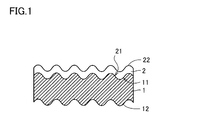
- FIG. 1 is a schematic cross-sectional view showing an example of a fiber laminate according to the first embodiment of the present invention.
- the fiber laminate shown in FIG. 1 includes a first fiber layer 1 composed of a first fiber assembly, and a second fiber layer disposed on the first main surface 11 and composed of a second fiber assembly. 2 is included.
- the first fiber layer 1 includes a first main surface (inner main surface) 11 that is a main surface on the second fiber layer 2 side, and a second main surface that is opposite to the second fiber layer 2 and that is opposite to the second fiber layer 2.
- the second fiber layer 2 includes a first main surface (inner main surface) 21 that is a main surface on the first fiber layer 1 side and a second main surface that is opposite to the first fiber layer 1 and that is opposite to the first fiber layer 1. And a main surface (outer main surface) 22.
- the first main surface 11 of the first fiber layer 1 is composed of surface irregularities, and the second fiber layer 2 is laminated thereon.
- the second fiber layer 2 is in contact with the first main surface 11 of the first fiber layer 1 over the entire surface or substantially the entire surface.
- the first main surface 21 of the second fiber layer 2 also has surface unevenness that is a transfer type (or approximately transfer type) of the surface unevenness of the first main surface 11 of the first fiber layer 1. That is, the interface between the first fiber layer 1 and the second fiber layer 2 is constituted by irregularities.
- corrugation which the 1st main surface 11 of the 1st fiber layer 1 and / or the 1st main surface 21 of the 2nd fiber layer 2 may have is named generically, and it is also called “the 1st surface unevenness
- the second fiber layer 2 of the second main surface 22 also has surface irregularities.
- the surface unevenness that the second main surface (outer main surface) 22 of the second fiber layer 2 may have is also referred to as “second surface unevenness”.
- the first fiber layer 1 also has surface irregularities on its second main surface 12.
- the surface unevenness that the second main surface (outer main surface) 12 of the first fiber layer 1 may have is also referred to as “third surface unevenness”.
- the fiber laminate according to the present embodiment includes the first main surface 11 and the second main surface 11 of the first fiber layer 1.
- One feature is that at least one of the first principal surfaces 21 of the fiber layer 2 has first surface irregularities.
- the fiber laminate according to the present embodiment can have both high ventilation performance and high collection performance.
- the fiber laminate according to the present embodiment can be suitably used for filter media such as air filter media and masks. When the fiber laminate according to the present embodiment is applied to, for example, a human mask, it has high ventilation performance (low pressure loss), so that it is difficult to feel breathlessness and long-term wearability (even if worn for a long time).
- the fiber laminate according to the present embodiment uses the second surface unevenness of the second main surface 22 of the second fiber layer 2 to make a human body, clothing, and the like.
- it can be used as a cleaning tool typified by a wiper for removing foreign substances attached to an article as described above.
- the main surface having the first surface irregularities may have at least a portion of the first surface irregularities, and it is not necessary that all of them are constituted by the first surface irregularities.
- the main surface having the first surface irregularities is (or approximately all) of the first surface irregularities. The same applies to the second and third surface irregularities.
- the 1st fiber layer 1 is a layer comprised by the 1st fiber aggregate, and the 1st principal surface (inner principal surface) 11 (major surface by the side of the 2nd fiber layer 2) is the 1st.
- the second main surface (outer main surface) 12 has third surface unevenness.
- the first major surface 11 is preferably composed of first surface irregularities, and the second major surface 12 is preferably composed of third surface irregularities.
- the first surface unevenness of the first main surface 11 is a surface forming an interface with the second fiber layer 2 (therefore, the first main surface 21 of the second fiber layer also has the first surface unevenness).
- the convex part which the 1st main surface (inner main surface) 11 and the 2nd main surface (outer main surface) 12 have may exist regularly, and may exist randomly.
- the shape of the convex portion is not particularly limited, and may be, for example, a conical shape, a cylindrical shape, a pyramid shape, or a raised shape.
- the height of the convex portions constituting the first surface irregularities of the first main surface (inner main surface) 11 is 0.1 mm or more, preferably 0.2 mm. It is above, More preferably, it is 0.3 mm or more (for example, 0.4 mm or more).
- the height of the convex portion is usually 5 mm or less, preferably 3 mm or less (for example, 2 mm or less). If the convex portion is too low and the height is less than 0.1 mm and the first main surface 11 is relatively smooth, the improvement of the collection performance is not recognized or insufficient. When the convex portion is too high, it is disadvantageous in terms of mechanical strength of the fiber laminate.
- the density of the convex portions in the first surface irregularities is preferably 3 pieces / cm 2 or more, and more preferably 10 pieces / cm 2 or more.
- the density of the convex portions is usually 50 pieces / cm 2 or less, and typically 30 pieces / cm 2 or less. If the density of the convex portions is excessively large, the air permeability of the fiber laminate may be adversely affected.
- the height and density of the protrusions are measured according to the method described in the example section using a tabletop microscope.
- the height and density of the convex portions constituting the third surface irregularities can be the same as the height and density of the convex portions constituting the first surface irregularities of the first fiber layer 1, respectively.
- the first fiber aggregate constituting the first fiber layer 1 may be composed of a woven fabric, but is preferably a non-woven fiber aggregate. Among these, the first fiber aggregate is more preferably a melt blown nonwoven fiber aggregate.
- melt-blowing method it is possible to easily and inexpensively manufacture a nonwoven fiber assembly having a small bulk density and excellent air permeability and having first surface irregularities and further third surface irregularities.
- a general melt blow spinning apparatus can be used for the melt blow method.
- the 1st fiber layer 1 is manufactured as a fiber web obtained by collecting the fiber flow injected from the nozzle on the uneven surface of the collection body. That is, when the fibers enter and solidify into the recesses (or the penetrating portions) of the collection surface, irregularities are imparted to one main surface or both main surfaces of the first fiber assembly.
- the collector can be a metal collector provided with a plurality of (or many) convex portions or concave portions, a metal mesh having a mesh, a cloth cloth, or the like. Among them, it is preferable to use a net having a three-dimensional structure generally called a conveyor net, whereby a non-woven fiber assembly having first surface unevenness and further third surface unevenness can be more easily manufactured.
- the raised portion constituting the first surface unevenness may be a raised protrusion.
- the raised protrusions are preferably rigid.
- the convex portion tends to be a raised protrusion.
- the fiber laminate is sprayed on the first main surface 11 of the first fiber assembly (first fiber layer 1) prepared in advance by a fiber that forms the second fiber assembly by a melt blow method or the like.
- the convex portion constituting the first surface irregularity is a raised projection, the bonding strength between the first fiber layer 1 and the second fiber layer 2 is increased, and thereby the fiber laminate. Can increase the durability.
- the average fiber diameter (first average fiber diameter) of the fibers constituting the first fiber aggregate is preferably 5 to 50 ⁇ m, more preferably 7 to 25 ⁇ m.
- the first fiber aggregate (first fiber) has a rigidity sufficient to maintain the shape of the first surface unevenness and further the third surface unevenness even after the fiber laminate is formed. Can be applied to layer 1). Further, setting the first average fiber diameter in the above range is advantageous in improving the balance between the ventilation performance and the collection performance of the fiber laminate. If the first average fiber diameter is too small, the ventilation performance tends to deteriorate. If the first average fiber diameter is too large, the collection performance tends to be lowered.
- the fibers constituting the first fiber assembly usually include fibers made of a thermoplastic resin.
- thermoplastic resins include polyolefin resins (low density, medium density or high density polyethylene, poly C 2-4 olefin resins such as polypropylene); styrene resins (heat resistant polystyrene, etc.); polyester resins ( Polyethylene terephthalate resin, polytrimethylene terephthalate resin, polybutylene terephthalate resin, poly C 2-4 alkylene arylate resin such as polyethylene naphthalate resin, etc.); polyamide resin (polyamide 6, polyamide 66, polyamide 11, polyamide 12, Aliphatic polyamide resins such as polyamide 610 and polyamide 612, semi-aromatic polyamide resins, aromatic polymers such as polyphenylene isophthalamide, polyhexamethylene terephthalamide, poly p-phenylene terephthalamide De resins); polycarbonate resin (bisphenol A polycarbonate); including cellulose resin (cellulose
- polypropylene is preferably used.
- a polyolefin-based resin, particularly polypropylene can be easily charged by a charging process described later, so that a fiber laminate having a higher filtration performance (collecting performance) by charging can be obtained more easily.
- the fiber which comprises a 1st fiber assembly contains a polypropylene
- the said fiber may be comprised only with the polypropylene and may contain thermoplastic resins other than a polypropylene.
- the content of polypropylene is preferably 50% by mass or more, more preferably 70% by mass or more, and further preferably 90% by mass or more.
- the fibers constituting the first fiber aggregate are conventional additives such as stabilizers (heat stabilizers, ultraviolet absorbers, light stabilizers, antioxidants, etc.), antibacterial agents, deodorants, fragrances, and colorants. (Dyes and pigments), fillers, antistatic agents, flame retardants, plasticizers, lubricants and the like may be contained. Only 1 type may be used for an additive and it may use 2 or more types together.
- the additive may be supported on the fiber surface or may be contained in the fiber.
- the melt flow rate (MFR, 230 ° C., 21.18 N load) of polypropylene is preferably 400 g / 10 min or less, more preferably 200 g / 10 min or less. If the MFR exceeds 400 g / 10 min, the fiber flow discharged from the nozzle is easily thinned, and it may be difficult to maintain a high average fiber diameter. From the viewpoint of resin dischargeability from the nozzle, the MFR of polypropylene is preferably 10 g / min or more.
- the intrinsic viscosity of the polyester resin is preferably 0.7 or more, more preferably 0.8 to 1.5.
- the relative viscosity of the polyamide resin is preferably 2 or more, and preferably 2.2 to 3.0.
- the first fiber aggregate is a melt blown nonwoven fiber aggregate
- the first fibers exhibiting rigidity sufficient to maintain the shape of the first surface irregularities and further the third surface irregularities even after the fiber laminate is formed.
- the fiber is solidified by increasing the fiber diameter by shortening the collection distance of the fiber flow or increasing the resin viscosity. It is preferable to lengthen the time until.
- the collection distance is, for example, 5 to 100 cm, and preferably 10 to 60 cm.
- the resin viscosity is, for example, 10 to 100 Pa ⁇ s, preferably 20 to 50 Pa ⁇ s, although it depends on the resin used and the melting temperature.
- the basis weight W 1 of the first fiber layer 1 is preferably 5 to 100 g / m 2 from the viewpoint of ventilation performance and collection performance (foreign material collection efficiency and / or collection capacity). More preferably, it is 10 to 50 g / m 2 or more. If the basis weight W 1 is too small, it is difficult to obtain sufficient filtration performance. If the basis weight W 1 is too large, it is difficult to obtain good ventilation performance.
- the density (bulk density) D 1 of the first fiber layer 1 in the fiber laminate is preferably 0.005 to 0.5 g / cm 3 and more preferably 0.01 to 0.2 g from the viewpoint of air permeability. / Cm 3 . If the density D 1 is too large, the ventilation performance may be reduced. If the density D 1 is too small, sufficient filtration performance is difficult to obtain, and the mechanical strength of the fiber laminate may be reduced.
- the thickness T 1 of the first fiber layer 1 in the fiber laminate is preferably from 0.3 to 5 mm, more preferably from the viewpoint of ventilation performance and collection performance (foreign material collection efficiency and / or collection capacity). Is 0.4 to 3 mm. By setting the thickness T 1 in the above range, it becomes easy to obtain the first fiber layer 1 exhibiting the above-described rigidity, and good ventilation performance and collection performance (including collection capacity) can be obtained. .
- the permeability of the first fiber layer 1 is the permeability according to the Frazier method, preferably 100 to 1000 cc / cm 2 / s. More preferably, it is 110 to 800 cc / cm 2 / s, and still more preferably 120 to 500 cc / cm 2 / s (for example, 130 to 400 cc / cm 2 / s). If the air permeability of the first fiber layer 1 is too low, the air permeability of the fiber laminate tends to be insufficient. If the air permeability of the first fiber layer 1 is too high, it is difficult to obtain sufficient collection performance.
- the 2nd fiber layer 2 is a layer comprised by a 2nd fiber assembly, and the 1st main surface (inner main surface) 21 (main surface by the side of the 1st fiber layer 1) is the 1st.
- the first main surface (outer main surface) 22 can have second surface unevenness.
- the first main surface 21 is preferably made of first surface unevenness
- the second main surface 22 is preferably made of second surface unevenness. From the viewpoint of improving the collection performance and ventilation performance of the fiber laminate, it is preferable that at least the first main surface 11 of the first fiber layer 1 has first surface irregularities as in the present embodiment, and the first fiber layer It is more preferable that both the first main surface 11 of 1 and the first main surface 21 of the second fiber layer 2 have first surface irregularities.
- the convex portions of the first main surface (inner main surface) 21 and the second main surface (outer main surface) 22 of the second fiber layer 2 may exist regularly or randomly. Good.
- the shape of the second convex portion is not particularly limited, and may be, for example, a conical shape, a cylindrical shape, a pyramid shape, or a raised shape.
- the height of the convex portions constituting the second surface irregularities of the second main surface 22 is preferably 0.05 mm or more, more preferably 0.1 mm or more. More preferably, it is 0.2 mm or more (for example, 0.3 mm or more).
- the height of the convex portion is usually 5 mm or less, preferably 3 mm or less (for example, 2 mm or less). If the convex portion is too low and its height is less than 0.05 mm and the second main surface 22 is smooth, improvement in the collection performance is not recognized or insufficient. When the convex portion is too high, it is disadvantageous in terms of mechanical strength of the fiber laminate.
- the density of the convex portions in the second surface irregularities is preferably 3 pieces / cm 2 or more, and more preferably 10 pieces / cm 2 or more.
- the density of the convex portions is usually 50 pieces / cm 2 or less, and typically 30 pieces / cm 2 or less. If the density of the convex portions is excessively large, the air permeability of the fiber laminate may be adversely affected.
- the second fiber aggregate constituting the second fiber layer 2 may be composed of a woven fabric, but is preferably a nonwoven fiber aggregate. Among these, the second fiber aggregate is more preferably a melt blown nonwoven fiber aggregate.
- the second fiber assembly (second fiber layer 2) made of fibers having a desired average fiber diameter is subjected to a bonding process using a separate heat-sealing process such as hot embossing or an adhesive. Without carrying out, it becomes easy to laminate on the 1st fiber layer 1 produced beforehand, or to make it contact
- the average fiber diameter (second average fiber diameter) of the fibers constituting the second fiber aggregate is preferably smaller than the average fiber diameter (first average fiber diameter) of the fibers constituting the first fiber aggregate.
- the second average fiber diameter is preferably 0.5 to 2 ⁇ m, more preferably 0.7 to 1.5 ⁇ m.
- the second average fiber diameter is in the range, the collection performance of the fiber laminate can be improved, and the balance between the ventilation performance and the collection performance of the fiber laminate can be improved. If the second average fiber diameter is too small, it may be disadvantageous in terms of ventilation performance. An excessively large second average fiber diameter can be disadvantageous in terms of collection performance.
- the specific example of the fiber material constituting the second fiber assembly can be the same as that of the first fiber assembly.
- polyolefin resins, polyester resins, and polyamide resins are preferably used, and polyolefin resins are more preferably used.
- the fibers constituting the second fiber assembly may contain two or more kinds of thermoplastic resins.
- polypropylene is preferably used.
- a polyolefin-based resin, particularly polypropylene, can be easily charged by a charging process described later, so that a fiber laminate having a higher filtration performance (collecting performance) by charging can be obtained more easily.
- the fibers constituting the second fiber assembly include polypropylene
- the fibers may be composed only of polypropylene or may include a thermoplastic resin other than polypropylene.
- the content of polypropylene is preferably 50% by mass or more, more preferably 70% by mass or more, and further preferably 90% by mass or more.
- the fibers constituting the second fiber assembly are conventional additives such as stabilizers (thermal stabilizers, ultraviolet absorbers, light stabilizers, antioxidants, etc.), antibacterial agents, deodorants, fragrances, and coloring agents. (Dyes and pigments), fillers, antistatic agents, flame retardants, plasticizers, lubricants and the like may be contained. Only 1 type may be used for an additive and it may use 2 or more types together.
- the additive may be supported on the fiber surface or may be contained in the fiber.
- the melt flow rate (MFR, 230 ° C., 21.18 N load) of polypropylene is preferably 500 g / 10 minutes or more, more preferably 700 g / 10 minutes or more.
- MFR melt flow rate
- the MFR of polypropylene is preferably 2000 g / min or less.
- the second average fiber diameter of the fibers constituting the second fiber assembly is the same as the fiber fiber collecting distance compared to the time of manufacturing the first fiber assembly. It can be controlled by adjusting the melt-blowing conditions such as increasing the length.
- the basis weight W 2 of the second fiber layer 2 is preferably smaller than that of the first fiber layer 1 (first fiber aggregate), and the ventilation performance and collection performance (contamination efficiency of foreign matter and From the viewpoint of (or collection capacity), it is preferably 0.5 to 30 g / m 2 , more preferably 1 to 10 g / m 2 or more. If the basis weight W 2 is too small, it is difficult to obtain sufficient collection performance. If the basis weight W 2 is too large, it is difficult to obtain good ventilation performance.
- the density (bulk density) D 2 of the second fiber layer 2 in the fiber laminate is preferably 0.007 to 0.4 g / cm 3 and more preferably 0.015 to 0.3 g from the viewpoint of air permeability. / Cm 3 . If the density D 2 is too large, the ventilation performance may be reduced. If the density D 2 is too small, it is difficult to obtain sufficient collection performance.
- the thickness T 2 of the second fiber layer 2 in the fiber laminate is preferably smaller than the thickness of the first fiber layer 1, and from the viewpoints of ventilation performance and collection performance (foreign material collection efficiency and / or collection capacity). Therefore, it is preferably 0.01 to 2 mm, more preferably 0.03 to 1 mm, and still more preferably 0.03 to 0.5 mm (for example, 0.1 mm or less). By setting the thickness T 2 in the above range, the balance between the ventilation performance and the collection performance is improved.
- the first fiber layer 1 and the first It is preferable to appropriately adjust at least one (preferably 2 or more, more preferably all) of the thickness ratio, the basis weight ratio, and the density (bulk density) ratio with the two fiber layers 2.
- the first and the thickness T 1 of the fibrous layer 1 ratio T 1 / T 2 of the the thickness T 2 of the second fibrous layer 2 is preferably 4 to 25, more preferably 6 to 20.
- first and basis weight W 1 of the fiber layer 1 ratio W 1 / W 2 of the basis weight W 2 of the second fibrous layer 2 is preferably 3-20, more preferably 4-15.
- the first density of the fiber layer 1 (bulk density) D 1 and the ratio D 1 / D 2 of the second density of the fiber layer 2 (bulk density) D 2 is preferably 0.2 to 0.99, and more Preferably, it is 0.3 to 0.8.
- the thickness (total thickness) of the fiber laminate is preferably 0.4 to 7 mm, more preferably 0.5 to 5 mm, from the viewpoint of mechanical strength and handleability.
- the basis weight of the fiber laminate (total basis weight) is 5.5 to 120 g / m 2 , more preferably 10 to 60 g / m 2 or more.
- the density of the fiber laminate (total density (bulk density)) is preferably 0.005 to 0.5 g / cm 3 , more preferably 0.01 to 0.2 g / cm 3. 3 , more preferably 0.1 g / cm 3 or less (for example, 0.01 to 0.1 g / cm 3 ).
- the permeability of the fiber laminate is the permeability by the Frazier method, preferably 80 to 1000 cc / cm 2 / s, more preferably 100 cc / cm 2 / s. s or more (for example, 100 to 800 cc / cm 2 / s), more preferably 110 to 500 cc / cm 2 / s (for example, 120 to 400 cc / cm 2 / s). If the air permeability of the fiber laminate is too high, it is difficult to obtain sufficient collection performance.
- the fiber laminate according to the present embodiment can be suitably used, for example, as a filter medium, and the collection efficiency measured according to JIS T 8151 can be 85% or more, and further 90% or more.
- the fiber laminate according to the present embodiment may have a pressure loss measured in accordance with JIS T 8151 of 10 Pa or less, and further 5 Pa or less.
- the fiber laminate according to the present embodiment can have a QF value representing filter medium performance of 0.6 or more, further 0.8 or more, and even more 0.9 or more (for example, 1 or more).
- the definition of the QF value is as described in the example section.
- the fiber laminate is formed by spraying (preferably thinly) fibers forming the second fiber aggregate on the first main surface 11 of the first fiber aggregate (first fiber layer 1) prepared in advance by a melt blow method or the like. Can be manufactured by. According to this method, the fiber group sprayed on the first main surface 11 is solidified on the first main surface 11 in a state of being in close contact with the surface (or in a state in which many portions are in close contact). A fiber laminate having good bonding strength between the fiber layer 1 and the second fiber layer 2 can be obtained. This eliminates the need for a separate heat-sealing process such as hot embossing or a bonding process using an adhesive or the like, as described above. The bonding between the first fiber layer 1 and the second fiber layer 2 by heat fusion and the presence of an intervening layer such as an adhesive tends to lower the ventilation performance of the fiber laminate.
- the shape of the first surface unevenness and the second surface unevenness of the second fiber layer 2 generally reflects the first surface unevenness.
- the shape of the 1st surface unevenness and the 2nd surface unevenness which the 2nd fiber layer 2 has does not need to reflect the 1st surface unevenness in all.
- the fiber laminate according to the present invention may be one that has been subjected to electrification treatment (those imparted with chargeability) in order to further improve the collection performance.
- Charging refers to the state in which the fiber laminate is charged with electricity, preferably the surface charge density (the amount of charge measured using a Faraday cage [electrostatic charge meter] divided by the measurement area). Value) is 1.0 ⁇ 10 ⁇ 10 coulomb / cm 2 or more, more preferably 1.5 ⁇ 10 ⁇ 10 coulomb / cm 2 or more, and even more preferably 2.0 ⁇ 10 ⁇ 10 coulomb / cm 2 or more. is there.
- Methods for imparting chargeability to the fiber laminate include a method of imparting electric charge by friction and contact, a method of irradiating active energy rays (for example, electron beam, ultraviolet ray, X-ray, etc.), gas discharge such as corona discharge, plasma, etc. And a suitable electret treatment such as a method using a high electric field, a hydrocharging method using a polar solvent such as water, and the like.
- the corona discharge method and the hydrocharging method are preferable because high chargeability can be obtained with a relatively low electric energy, and the hydrocharging method is more preferable because the chargeability can be imparted uniformly in the thickness direction.
- a polar solvent such as water or an organic solvent (preferably water from the viewpoint of productivity such as wastewater treatment) is sprayed on the fiber laminate or vibrated while spraying.
- the pressure of the polar solvent colliding with the fiber laminate is preferably 0.1 to 5 MPa, more preferably 0.5 to 3 MPa, and the suction pressure from the lower part is preferably 500 to 5000 mmH 2 O, more preferably 1000 ⁇ 3000 mmH 2 O.
- the treatment time for hydrocharging is preferably 0.01 to 5 seconds, more preferably 0.02 to 1 second.
- the charged fiber laminate after the hydrocharging method is preferably dried at a temperature of 40 to 100 ° C., preferably 50 to 80 ° C., for example.
- the apparatus and conditions used for the corona discharge method are not particularly limited.
- a DC high voltage stabilized power source is used.
- a linear distance between electrodes to which a voltage is applied 5 to 70 mm (preferably 10 to 30 mm)
- an applied voltage ⁇ 50 to ⁇ 10 kV and / or 10 to 50 kV (preferably ⁇ 40 to ⁇ 20 kV and / or 20 to 40 kV)
- temperature normal temperature (20 ° C.) to 100 ° C. (preferably 30 to 80 ° C.)
- treatment time 0.
- the reaction can be performed for 1 to 20 seconds (preferably 0.5 to 10 seconds).
- the fiber laminate according to the present embodiment can be suitably used as a filter medium.
- the filter medium include a human mask and an industrial filter medium (for example, an industrial air filter medium).
- the second main surface 12 of the first fiber layer 1 is configured with a relatively smooth surface (for example, a surface where the height of the convex portion is less than 0.1 mm).
- a relatively smooth surface for example, a surface where the height of the convex portion is less than 0.1 mm.
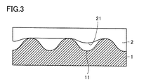
- the first surface irregularities of the first fiber layer 1 and the first surface irregularities of the second fiber layer 2 do not need to be in contact with each other, and the first fiber layer 1 and the second fibers You may have the part which both do not contact between the layers 2.
- the first surface unevenness is formed on at least a part of the first main surface 21 of the second fiber layer 2, and the first surface unevenness and the first surface unevenness of the second fiber layer 2 are in contact with each other in this region. Can be mentioned.
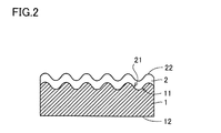
- the present invention it is sufficient that at least one of the first main surface 11 of the first fiber layer 1 and the first main surface 21 of the second fiber layer 2 has the first surface unevenness, For example, as shown in FIG. 4, only the first fiber layer 1 has a first surface unevenness, and as shown in FIG. 5, only the second fiber layer 2 has a first surface unevenness. There may be.
- the present invention will be described more specifically with reference to examples. However, the present invention is not limited to these examples.
- the measuring method of each physical-property value in a following example and a comparative example is as follows.
- the thickness direction from the top of the convex portion of the second surface irregularities of the second fiber layer to the back surface of the fiber laminate (the second main surface of the first fiber layer, or the convex portion vertex when there are irregularities)
- the distance was measured at arbitrary 10 locations (however, 2 adjacent locations have a 1 mm spacing), and the average value of these was taken as the “thickness of the fiber laminate”.
- it is a convex part when there exists an unevenness
- the thickness direction distance to the apex was measured at any 10 locations (however, 2 adjacent locations have a 1 mm spacing), and the average value of these was defined as the “thickness of the first fiber layer”. .
- the “thickness of the first fiber layer” was subtracted from the “thickness of the fiber laminate” to obtain the “thickness of the second fiber layer”.
- the second surface irregularities of the second fiber layer from the surface of the second fiber layer excluding the convex portions of the first surface irregularities (surface irregularities on the first fiber layer side).
- the distance in the thickness direction to the top of the convex portion was measured at any five locations (however, two adjacent locations had a 1 mm interval), and the average value of these was determined.
- the average value was subtracted from the “thickness of the second fiber layer” obtained in [2] above to obtain “the height of the convex portions of the first surface irregularities” in the second fiber layer.
- the “height of the convex portions of the second surface irregularities” in the second fiber layer is measured as follows. Based on the photograph obtained in [2] above, the back surface of the fiber laminate from the surface of the second fiber layer excluding the convex portions of the second surface irregularities (if there are irregularities on the second main surface of the first fiber layer, irregularities) The distance in the thickness direction to the vertex of the convex part) is measured at any five locations (however, two adjacent locations have an interval of 1 mm), and an average value thereof is obtained. The average value is subtracted from the “thickness of the fiber laminate” obtained in [2] above to obtain the “height of the convex portions of the second surface irregularities” in the second fiber layer.
- the “density of convex portions of the second surface unevenness” in the second fiber layer is measured as follows.
- the distance in the thickness direction from the vertex of the convex portion of the second surface irregularity of the second fiber layer to the first main surface of the second fiber layer (the surface excluding the convex portion when there is irregularity) is any 10 locations (however, , Two adjacent points have an interval of 1 mm.), And a line perpendicular to the thickness direction is drawn at a position (height) of 1/3 of the average value.
- the number of protrusions protruding from this line per 1 cm is defined as “the number of MD protrusions”.
- the same measurement is performed on the cross section parallel to the CD direction to obtain the “number of CD protrusions”.
- corrugation" in a 2nd fiber layer is calculated
- the first surface which is a melt-blown nonwoven fiber aggregate on the first surface irregularities of the first fiber layer according to the following conditions
- a second fiber aggregate (second fiber layer) having a basis weight of 2.7 g / m 2 having irregularities and second surface irregularities was formed to obtain a fiber laminate.
- FIG. 6 shows a tabletop micrograph of one section of the fiber laminate obtained in Example 1. It can be seen that the first fiber layer has first surface irregularities, and the second fiber layer has first surface irregularities and second surface irregularities.
- the convex portion constituting the first surface irregularity was a raised convex portion (the same applies to Examples 2 to 6).
- the obtained fiber laminate was charged by a hydrocharging method.
- Specific conditions for the hydrocharging method are as follows.
- Example 2 A first fiber assembly (first fiber layer) was obtained in the same manner as in Example 1 except that the distance from the nozzle to the conveyor net was changed to 15 cm and the basis weight was 15.0 g / m 2 . Thereafter, a fiber laminate was produced in the same manner as in Example 1.
- Example 3 Example 1 except that the type of conveyor net was changed to a balance type (width pitch 2.5 mm ⁇ length pitch 3 mm ⁇ thickness 4 mm, 0.8 mm ⁇ ) and the distance from the nozzle to the conveyor net was changed to 20 cm. In the same manner as above, a first fiber assembly (first fiber layer) was obtained. Thereafter, a fiber laminate was produced in the same manner as in Example 1.
- Example 4 A fiber laminate was produced in the same manner as in Example 2 except that the basis weight of the first fiber layer was 10 g / m 2 .
- Example 5 A first fiber assembly (first fiber layer) was obtained in the same manner as in Example 3 except that the distance from the nozzle to the conveyor net was changed to 25 cm and the basis weight was 30.0 gm 2 . Thereafter, a fiber laminate was produced in the same manner as in Example 3.
- Example 6 In the formation of the second fiber layer, a fiber laminate was produced in the same manner as in Example 1 except that the distance from the nozzle to the conveyor net was changed to 40 cm. In this fiber laminate, the convex portion of the first main surface (first fiber layer side surface) of the second fiber layer had a height of 0.005 mm at the maximum.
- a fiber laminate was manufactured in the same manner as in Example 1 except that the type of the conveyor net was changed to a 200 mesh plain woven stainless steel wire mesh.
- the first main surface (second fiber layer side surface) of the first fiber layer and the convex portions of the first main surface (first fiber layer side surface) of the second fiber layer have a height.
- the pressure loss was high and the QF value was high as compared with the fiber laminate of the example.
Landscapes
- Chemical & Material Sciences (AREA)
- Chemical Kinetics & Catalysis (AREA)
- Engineering & Computer Science (AREA)
- Textile Engineering (AREA)
- Nonwoven Fabrics (AREA)
- Laminated Bodies (AREA)
- Filtering Materials (AREA)
- Cleaning Implements For Floors, Carpets, Furniture, Walls, And The Like (AREA)
- Electrostatic Separation (AREA)
Abstract
Description
[1] 第1主面を有し、第1繊維集合体で構成される第1繊維層と、
前記第1主面上に配置される繊維層であって、第2繊維集合体で構成される第2繊維層と、
を含み、
前記第1主面及び前記第2繊維層における前記第1繊維層側の主面の少なくともいずれか一方は、第1表面凹凸を有し、
前記第1表面凹凸を構成する凸部の高さが0.1mm以上である、繊維積層体。
QF値=-ln(1-捕集効率(%)/100)/圧力損失(Pa)
に従って算出されるQF値が0.6以上である、[1]~[11]のいずれかに記載の繊維積層体。
[14] 濾材である、[1]~[13]のいずれかに記載の繊維積層体。
図1は、本発明の第1実施形態に係る繊維積層体の一例を示す概略断面図である。図1に示される繊維積層体は、第1繊維集合体で構成される第1繊維層1と、その第1主面11上に配置され、第2繊維集合体で構成される第2繊維層2とを含む。第1繊維層1は、第2繊維層2側の主面である第1主面(内側主面)11と、それに対向する、第2繊維層2とは反対側の主面である第2主面(外側主面)12とを有する。第2繊維層2は、第1繊維層1側の主面である第1主面(内側主面)21と、それに対向する、第1繊維層1とは反対側の主面である第2主面(外側主面)22とを有する。
(1)第1繊維層
第1繊維層1は第1繊維集合体で構成される層であり、第1主面(内側主面)11(第2繊維層2側の主面)は第1表面凹凸を有し、第2主面(外側主面)12は、第3表面凹凸を有する。第1主面11は、好ましくは第1表面凹凸からなり、第2主面12は、好ましくは第3表面凹凸からなる。第1主面11の第1表面凹凸は第2繊維層2との界面を形成する表面であり(従って第2繊維層の第1主面21も第1表面凹凸を有する。)、2つの繊維層の界面が凹凸で構成されることにより、繊維積層体の捕集性能及び通気性能を高めることができる。また第3表面凹凸を有することは、捕集性能及び通気性能のさらなる向上に有利となる。第1主面(内側主面)11及び第2主面(外側主面)12が有する凸部は、規則的に存在していてもよいしランダムに存在していてもよい。当該凸部の形状は特に制限されず、例えば円錐状、円柱状、角錐状、起毛状等であり得る。
第2繊維層2は、第2繊維集合体で構成される層であり、第1主面(内側主面)21(第1繊維層1側の主面)は第1表面凹凸を有することができ、第2主面(外側主面)22は、第2表面凹凸を有することができる。第1主面21は、好ましくは第1表面凹凸からなり、第2主面22は、好ましくは第2表面凹凸からなる。繊維積層体の捕集性能及び通気性能を高める観点からは、本実施形態のように、少なくとも第1繊維層1の第1主面11が第1表面凹凸を有することが好ましく、第1繊維層1の第1主面11及び第2繊維層2の第1主面21の双方が第1表面凹凸を有することがより好ましい。また、第2繊維層2の第2主面22が第2表面凹凸を有していると、捕集性能及び通気性能の向上に有利となる。第2繊維層2の第1主面(内側主面)21及び第2主面(外側主面)22が有する凸部は、規則的に存在していてもよいしランダムに存在していてもよい。第2凸部の形状は特に制限されず、例えば円錐状、円柱状、角錐状、起毛状等であり得る。
本実施形態に係る繊維積層体においては、表面凹凸を備えるだけでなく、通気性能と捕集性能とのより高度なバランスを付与するために、第1繊維層1と第2繊維層2との厚み比、目付比及び密度(嵩密度)比の少なくとも1つ(好ましくは2以上、より好ましくはすべて)を適切に調整することが好ましい。第1繊維層1の厚みT1と第2繊維層2の厚みT2との比T1/T2は、好ましくは4~25であり、より好ましくは6~20である。また、第1繊維層1の目付W1と第2繊維層2の目付W2との比W1/W2は、好ましくは3~20であり、より好ましくは4~15である。第1繊維層1の密度(嵩密度)D1と第2繊維層2の密度(嵩密度)D2との比D1/D2は、好ましくは0.2~0.99であり、より好ましくは0.3~0.8である。
図2~5を参照して、本発明の他の実施形態に係る繊維積層体について説明する。なお以下では、図1に示される繊維積層体と異なる点についてのみ述べることとし、その他の点については第1実施形態についての上の記述が引用される。
JIS L 1913「一般不織布試験方法」に準じて、繊維積層体全体としての目付、及び第1繊維層、第2繊維層の各層の目付を測定した。
卓上顕微鏡(日立ハイテクノロジーズ社製の「Miniscope TM3030」)を用いて、繊維積層体断面の50倍写真を撮影した。断面の露出にあたっては、カッターを用いて上から下に向かって押し切って(繊維積層体を切断した後、カッターを下から上に戻す操作を行うことなく)繊維積層体を切断した。得られた写真に基づき、第2繊維層の第2表面凹凸の凸部頂点から繊維積層体の裏面(第1繊維層の第2主面、凹凸がある場合は凸部頂点)までの厚み方向距離を任意の10か所(ただし、隣り合う2か所は、1mmの間隔を有する。)について測定し、これらの平均値を、「繊維積層体の厚み」とした。また、上記写真に基づき、第1繊維層の第1表面凹凸(第1主面)の凸部頂点から繊維積層体の裏面(第1繊維層の第2主面、凹凸がある場合は凸部頂点)までの厚み方向距離を任意の10か所(ただし、隣り合う2か所は、1mmの間隔を有する。)について測定し、これらの平均値を、「第1繊維層の厚み」とした。「繊維積層体の厚み」から「第1繊維層の厚み」を差し引いて、「第2繊維層の厚み」とした。
上記〔1〕で得られた目付値を上記〔2〕で得られた厚みで除することにより、繊維積層体全体としての密度、及び第1繊維層、第2繊維層の各層の密度を求めた。
上記〔2〕で得られた写真に基づき、第1表面凹凸の凸部を除いた第1繊維層の表面から繊維積層体の裏面(第1繊維層の第2主面、凹凸がある場合は凸部頂点)までの厚み方向距離を任意の5か所(ただし、隣り合う2か所は、1mmの間隔を有する。)について測定し、これらの平均値を求めた。上記〔2〕で得られた「第1繊維層の厚み」から当該平均値を差し引いて、第1繊維層における「第1表面凹凸の凸部の高さ」とした。
卓上顕微鏡(日立ハイテクノロジーズ社製の「Miniscope TM3030」)を用いて、繊維積層体のMD方向に平行な断面の50倍写真を撮影した。断面の露出にあたっては、カッターを用いて上から下に向かって押し切って(繊維積層体を切断した後、カッターを下から上に戻す操作を行うことなく)繊維積層体を切断した。第1繊維層の第1表面凹凸の凸部頂点から繊維積層体の裏面(第1繊維層の第2主面、凹凸がある場合は凸部頂点)までの厚み方向距離を任意の10か所(ただし、隣り合う2か所は、1mmの間隔を有する。)について測定し、これらの平均値の1/3の間隔(高さ)の位置に、厚み方向に垂直な線を引いた。この線から飛び出している凸部の1cm当たりの数を「MD凸部数」とした。CD方向に平行な断面についても同様に測定を行って「CD凸部数」を得た。そして、「MD凸部数」と「CD凸部数」との積として、第1繊維層における「第1表面凹凸の凸部の密度」を求めた。
走査型電子顕微鏡(日立ハイテクノロジーズ社製の「Miniscope TM3030」)を用いて、第1繊維層、第2繊維層の表面を500倍に拡大した写真を撮影した。写真中の任意の100本の繊維の径を測定し、これらの平均値を平均繊維径とした。ただし、融着した繊維は繊維径を明確に測定できないため対象外とした。
JIS L 1913「一般不織布試験方法」のフラジール形法に準拠して、繊維積層体の通気度(cc/cm2/s)を測定した。
〔8-1〕捕集効率(%)及び圧力損失(Pa)
JIS T 8151に準拠し、繊維積層体を11cmφの大きさに切り出してこれを濾過部8.6cmφの試料台にセットし(濾過面積:58.1cm2)、風量20L/分、面速度5.7cm/秒でNaCl粒子(平均粒径:0.1μm)を濾過したときの捕集効率(%)及び圧力損失(Pa)を測定した。
上記〔8-1〕で得られた捕集効率及び圧力損失から、下記式:
QF値=-ln(1-捕集効率(%)/100)/圧力損失(Pa)
に基づきQF値を算出した。
ポリプロピレン〔MFR(230℃、21.18N荷重)=30g/10分〕を溶融押出してノズル孔から吐出させ、熱風により細化させた繊維流を、コンベアネットが巻き付けられたロール上に捕集することにより、メルトブロー不織繊維集合体である第1表面凹凸を有する目付20.0g/m2の第1繊維集合体(第1繊維層)を得た。上記メルトブロー法の具体的条件は次のとおりである。
・孔間隔:1.50mm、
・紡糸温度:260℃、
・単孔吐出量:0.3g/分・孔、
・噴出熱風の温度:260℃、
・噴出熱風の流量:13Nm3/min(1m)、
・ノズルからコンベアネットまでの距離:32cm、
・コンベアネットの種類:バランスタイプ(幅ピッチ5mm×長さピッチ5mm×厚み5mm、1mmφ)。
・孔間隔:0.75mm、
・紡糸温度:215℃、
・単孔吐出量:0.036g/分・孔、
・噴出熱風の温度:215℃、
・噴出熱風の流量:10Nm3/min(1m)、
・ノズルからコンベアネットまでの距離:11cm。
・水の圧力:0.4MPa、
・吸引圧力:2000mmH2O、
・処理時間:0.042秒(処理幅14mm、速度20m/min)。
ノズルからコンベアネットまでの距離を15cmに変更したこと、及び目付を15.0g/m2としたこと以外は実施例1と同様にして第1繊維集合体(第1繊維層)を得た。その後は、実施例1と同様にして繊維積層体を製造した。
コンベアネットの種類をバランスタイプ(幅ピッチ2.5mm×長さピッチ3mm×厚み4mm、0.8mmφ)に変更したこと、及びノズルからコンベアネットまでの距離を20cmに変更したこと以外は実施例1と同様にして第1繊維集合体(第1繊維層)を得た。その後は、実施例1と同様にして繊維積層体を製造した。
第1繊維層の目付を10g/m2としたこと以外は実施例2と同様にして繊維積層体を製造した。
ノズルからコンベアネットまでの距離を25cmに変更したこと、及び目付を30.0gm2としたこと以外は実施例3と同様にして第1繊維集合体(第1繊維層)を得た。その後は、実施例3と同様にして繊維積層体を製造した。
第2繊維層の形成において、ノズルからコンベアネットまでの距離を40cmに変更したこと以外は実施例1と同様にして繊維積層体を製造した。この繊維積層体において、第2繊維層の第1主面(第1繊維層側表面)が有する凸部は、高さが最高でも0.005mmであった。
第1繊維層の形成において、コンベアネットの種類を200メッシュの平織ステンレス金網に変更したこと以外は実施例1と同様にして繊維積層体を製造した。この繊維積層体において、第1繊維層の第1主面(第2繊維層側表面)、及び第2繊維層の第1主面(第1繊維層側表面)が有する凸部は、高さが最高でも0.005mmであり、実施例の繊維積層体に比べて、圧力損失が高く、またQF値が高いものであった。

Claims (15)
- 第1主面を有し、第1繊維集合体で構成される第1繊維層と、
前記第1主面上に配置される繊維層であって、第2繊維集合体で構成される第2繊維層と、
を含み、
前記第1主面及び前記第2繊維層における前記第1繊維層側の主面の少なくともいずれか一方は、第1表面凹凸を有し、
前記第1表面凹凸を構成する凸部の高さが0.1mm以上である、繊維積層体。 - 前記第1表面凹凸を構成する凸部の密度が3個/cm2以上である、請求項1に記載の繊維積層体。
- 少なくとも前記第1主面は、前記第1表面凹凸を有する、請求項1又は2に記載の繊維積層体。
- 前記第2繊維層における前記第1繊維層とは反対側の主面が第2表面凹凸を有し、該第2表面凹凸を構成する凸部の高さが0.05mm以上である、請求項1~3のいずれか1項に記載の繊維積層体。
- 前記第2表面凹凸を構成する凸部の密度が3個/cm2以上である、請求項4に記載の繊維積層体。
- 嵩密度が0.1g/cm3以下である、請求項1~5のいずれか1項に記載の繊維積層体。
- 前記第1繊維層の厚みT1と前記第2繊維層の厚みT2との比T1/T2が4~25である、請求項1~6のいずれか1項に記載の繊維積層体。
- 前記第1繊維集合体及び前記第2繊維集合体は、不織繊維集合体である、請求項1~7のいずれか1項に記載の繊維積層体。
- 前記不織繊維集合体は、ポリオレフィン系樹脂繊維を含む、請求項8に記載の繊維積層体。
- 前記第2繊維集合体を構成する繊維の平均繊維径が0.5~2μmである、請求項1~9のいずれか1項に記載の繊維積層体。
- 通気度が100cc/cm2/s以上である、請求項1~10のいずれか1項に記載の繊維積層体。
- JIS T 8151に準拠して測定される捕集効率及び圧力損失がそれぞれ85%以上、10Pa以下であり、かつ、下記式:
QF値=-ln(1-捕集効率(%)/100)/圧力損失(Pa)
に従って算出されるQF値が0.6以上である、請求項1~11のいずれか1項に記載の繊維積層体。 - 帯電処理されている、請求項1~12のいずれか1項に記載の繊維積層体。
- 濾材である、請求項1~13のいずれか1項に記載の繊維積層体。
- 清掃用具である、請求項1~13のいずれか1項に記載の繊維積層体。
Priority Applications (3)
| Application Number | Priority Date | Filing Date | Title |
|---|---|---|---|
| KR1020177034530A KR102477321B1 (ko) | 2015-07-24 | 2016-07-21 | 섬유 적층체 |
| JP2017530820A JP7220984B2 (ja) | 2015-07-24 | 2016-07-21 | 繊維積層体 |
| CN201680029509.6A CN107614772A (zh) | 2015-07-24 | 2016-07-21 | 纤维叠层体 |
Applications Claiming Priority (2)
| Application Number | Priority Date | Filing Date | Title |
|---|---|---|---|
| JP2015146873 | 2015-07-24 | ||
| JP2015-146873 | 2015-07-24 |
Publications (1)
| Publication Number | Publication Date |
|---|---|
| WO2017018317A1 true WO2017018317A1 (ja) | 2017-02-02 |
Family
ID=57884763
Family Applications (1)
| Application Number | Title | Priority Date | Filing Date |
|---|---|---|---|
| PCT/JP2016/071411 Ceased WO2017018317A1 (ja) | 2015-07-24 | 2016-07-21 | 繊維積層体 |
Country Status (5)
| Country | Link |
|---|---|
| JP (1) | JP7220984B2 (ja) |
| KR (1) | KR102477321B1 (ja) |
| CN (1) | CN107614772A (ja) |
| TW (1) | TWI698346B (ja) |
| WO (1) | WO2017018317A1 (ja) |
Cited By (6)
| Publication number | Priority date | Publication date | Assignee | Title |
|---|---|---|---|---|
| WO2018174176A1 (ja) * | 2017-03-24 | 2018-09-27 | 日本バイリーン株式会社 | 帯電濾材及び帯電濾材の製造方法 |
| KR20190104734A (ko) * | 2018-03-02 | 2019-09-11 | 경희대학교 산학협력단 | 3d 프린터를 이용한 (초)미세먼지 분리막의 제조방법 |
| JP2020104270A (ja) * | 2018-12-26 | 2020-07-09 | 株式会社リコー | 払拭部材、払拭装置、液体吐出装置、及び払拭方法 |
| WO2021010178A1 (ja) | 2019-07-16 | 2021-01-21 | クラレクラフレックス株式会社 | 繊維構造体およびその製造方法 |
| JP2021188206A (ja) * | 2020-06-03 | 2021-12-13 | セイコーエプソン株式会社 | 繊維構造体製造装置、繊維構造体製造方法、繊維構造体 |
| JP2024034106A (ja) * | 2022-08-31 | 2024-03-13 | アイリスオーヤマ株式会社 | 清掃用シート |
Families Citing this family (4)
| Publication number | Priority date | Publication date | Assignee | Title |
|---|---|---|---|---|
| JP7352302B2 (ja) * | 2019-03-29 | 2023-09-28 | タピルス株式会社 | 液体フィルター用のメルトブロー不織布、当該メルトブロー不織布の積層体及び積層体を備える液体用フィルター |
| JP6831132B1 (ja) * | 2019-12-18 | 2021-02-17 | ヤマシンフィルタ株式会社 | 繊維積層体 |
| KR102954636B1 (ko) | 2019-12-23 | 2026-04-20 | 도레이 카부시키가이샤 | 스펀본드 부직포, 집진기 플리츠 필터용 여과재, 집진기 플리츠 필터 및 대풍량 펄스제트 타입 집진기 |
| JP6962494B1 (ja) * | 2019-12-23 | 2021-11-05 | 東レ株式会社 | スパンボンド不織布、フィルター積層濾材、集塵機プリーツフィルター用濾材、集塵機プリーツフィルターおよび中風量パルスジェットタイプ集塵機 |
Citations (9)
| Publication number | Priority date | Publication date | Assignee | Title |
|---|---|---|---|---|
| JPH04180808A (ja) * | 1990-11-13 | 1992-06-29 | Asahi Chem Ind Co Ltd | 成形フィルター |
| JPH07100316A (ja) * | 1993-10-05 | 1995-04-18 | Japan Vilene Co Ltd | フィルタ素材 |
| JP2007014638A (ja) * | 2005-07-08 | 2007-01-25 | Tsubakimoto Kogyo Kk | 液体塗布用シート、液体塗布用シート製造装置 |
| JP2009195845A (ja) * | 2008-02-22 | 2009-09-03 | Kureha Ltd | フィルター用不織布 |
| WO2010073451A1 (ja) * | 2008-12-25 | 2010-07-01 | 日本無機株式会社 | プリーツ型エアフィルタパック及びそれを用いたエアフィルタ |
| WO2011019022A1 (ja) * | 2009-08-10 | 2011-02-17 | 旭化成せんい株式会社 | 集じん機用ろ過布 |
| JP2013194333A (ja) * | 2012-03-16 | 2013-09-30 | Kao Corp | 不織布およびその製造方法 |
| JP2014012913A (ja) * | 2012-06-07 | 2014-01-23 | Kao Corp | 不織布 |
| JP2015092954A (ja) * | 2013-11-11 | 2015-05-18 | 花王株式会社 | 清掃シート |
Family Cites Families (3)
| Publication number | Priority date | Publication date | Assignee | Title |
|---|---|---|---|---|
| JPS525650B2 (ja) | 1973-01-19 | 1977-02-15 | ||
| JP5205650B2 (ja) * | 2008-05-15 | 2013-06-05 | クラレクラフレックス株式会社 | 積層体およびその製造方法 |
| JP5498474B2 (ja) * | 2011-12-14 | 2014-05-21 | 花王株式会社 | 積層不織布の製造方法 |
-
2016
- 2016-07-21 WO PCT/JP2016/071411 patent/WO2017018317A1/ja not_active Ceased
- 2016-07-21 JP JP2017530820A patent/JP7220984B2/ja active Active
- 2016-07-21 KR KR1020177034530A patent/KR102477321B1/ko active Active
- 2016-07-21 CN CN201680029509.6A patent/CN107614772A/zh active Pending
- 2016-07-22 TW TW105123251A patent/TWI698346B/zh active
Patent Citations (9)
| Publication number | Priority date | Publication date | Assignee | Title |
|---|---|---|---|---|
| JPH04180808A (ja) * | 1990-11-13 | 1992-06-29 | Asahi Chem Ind Co Ltd | 成形フィルター |
| JPH07100316A (ja) * | 1993-10-05 | 1995-04-18 | Japan Vilene Co Ltd | フィルタ素材 |
| JP2007014638A (ja) * | 2005-07-08 | 2007-01-25 | Tsubakimoto Kogyo Kk | 液体塗布用シート、液体塗布用シート製造装置 |
| JP2009195845A (ja) * | 2008-02-22 | 2009-09-03 | Kureha Ltd | フィルター用不織布 |
| WO2010073451A1 (ja) * | 2008-12-25 | 2010-07-01 | 日本無機株式会社 | プリーツ型エアフィルタパック及びそれを用いたエアフィルタ |
| WO2011019022A1 (ja) * | 2009-08-10 | 2011-02-17 | 旭化成せんい株式会社 | 集じん機用ろ過布 |
| JP2013194333A (ja) * | 2012-03-16 | 2013-09-30 | Kao Corp | 不織布およびその製造方法 |
| JP2014012913A (ja) * | 2012-06-07 | 2014-01-23 | Kao Corp | 不織布 |
| JP2015092954A (ja) * | 2013-11-11 | 2015-05-18 | 花王株式会社 | 清掃シート |
Cited By (12)
| Publication number | Priority date | Publication date | Assignee | Title |
|---|---|---|---|---|
| WO2018174176A1 (ja) * | 2017-03-24 | 2018-09-27 | 日本バイリーン株式会社 | 帯電濾材及び帯電濾材の製造方法 |
| CN110430931A (zh) * | 2017-03-24 | 2019-11-08 | 日本宝翎株式会社 | 带电过滤材料以及带电过滤材料的制造方法 |
| JPWO2018174176A1 (ja) * | 2017-03-24 | 2020-01-23 | 日本バイリーン株式会社 | 帯電濾材及び帯電濾材の製造方法 |
| KR20190104734A (ko) * | 2018-03-02 | 2019-09-11 | 경희대학교 산학협력단 | 3d 프린터를 이용한 (초)미세먼지 분리막의 제조방법 |
| KR102060135B1 (ko) * | 2018-03-02 | 2019-12-27 | 경희대학교 산학협력단 | 3d 프린터를 이용한 (초)미세먼지 분리막의 제조방법 |
| JP2020104270A (ja) * | 2018-12-26 | 2020-07-09 | 株式会社リコー | 払拭部材、払拭装置、液体吐出装置、及び払拭方法 |
| JP7115298B2 (ja) | 2018-12-26 | 2022-08-09 | 株式会社リコー | 払拭部材、払拭装置、液体吐出装置、及び払拭方法 |
| WO2021010178A1 (ja) | 2019-07-16 | 2021-01-21 | クラレクラフレックス株式会社 | 繊維構造体およびその製造方法 |
| KR20220034116A (ko) | 2019-07-16 | 2022-03-17 | 구라레 구라후렛쿠스 가부시키가이샤 | 섬유 구조체 및 그 제조 방법 |
| JP2021188206A (ja) * | 2020-06-03 | 2021-12-13 | セイコーエプソン株式会社 | 繊維構造体製造装置、繊維構造体製造方法、繊維構造体 |
| JP7567215B2 (ja) | 2020-06-03 | 2024-10-16 | セイコーエプソン株式会社 | 繊維構造体製造装置、繊維構造体製造方法、繊維構造体 |
| JP2024034106A (ja) * | 2022-08-31 | 2024-03-13 | アイリスオーヤマ株式会社 | 清掃用シート |
Also Published As
| Publication number | Publication date |
|---|---|
| TWI698346B (zh) | 2020-07-11 |
| JPWO2017018317A1 (ja) | 2018-05-10 |
| JP7220984B2 (ja) | 2023-02-13 |
| KR102477321B1 (ko) | 2022-12-13 |
| TW201710065A (zh) | 2017-03-16 |
| CN107614772A (zh) | 2018-01-19 |
| KR20180033123A (ko) | 2018-04-02 |
Similar Documents
| Publication | Publication Date | Title |
|---|---|---|
| JP7220984B2 (ja) | 繊維積層体 | |
| KR100982235B1 (ko) | 폴리올레핀 단섬유로 제조된 스펀레이스 부직포로 구성된정전필터층을 포함하는 에어필터 | |
| US8206481B2 (en) | HEPA (H-10) performance synthetic nonwoven and nanofiber composite filter media | |
| US20080315464A1 (en) | Method of manufacturing a composite filter media | |
| US20110064928A1 (en) | Nonwoven material | |
| JP4902788B2 (ja) | 細径繊維のシート状集合体、その製造方法およびその製造装置 | |
| US10688432B2 (en) | Filter medium and filter unit | |
| US20120186452A1 (en) | Multiple Layer HEPA Filter and Method of Manufacture | |
| RU2526777C2 (ru) | Фильтровальный мешок пылесоса | |
| KR20220034116A (ko) | 섬유 구조체 및 그 제조 방법 | |
| KR101905563B1 (ko) | 부직포 적층체, 그의 제조 방법 및 이를 포함하는 캐빈 에어 필터 | |
| US10071334B2 (en) | Filter medium and filter unit | |
| JP2007046478A (ja) | 内燃機関エアクリーナ用濾材およびエアクリーナエレメント | |
| JP5918641B2 (ja) | プリーツ型エアフィルタ用濾材及びプリーツ型エアフィルタユニット | |
| WO2018174176A1 (ja) | 帯電濾材及び帯電濾材の製造方法 | |
| JP6133035B2 (ja) | 静電フィルター | |
| KR20190084242A (ko) | 공기 청정 필터, 하이브리드 공기 청정 필터 및 공기 청정기 | |
| JP2000153122A (ja) | フィルタユニット | |
| JP7154780B2 (ja) | 積層帯電濾材 | |
| JP4126679B2 (ja) | フィルタ及びその製造方法 | |
| US20240349826A1 (en) | Disposable, Compostable Surgical/Medical Masks and Methods of Production Therefor | |
| KR20240026178A (ko) | 섬유 구조체 및 그 용도 | |
| KR20230067222A (ko) | 공기정화용 정전 나노 복합 부직포 및 그의 제조방법 |
Legal Events
| Date | Code | Title | Description |
|---|---|---|---|
| 121 | Ep: the epo has been informed by wipo that ep was designated in this application |
Ref document number: 16830422 Country of ref document: EP Kind code of ref document: A1 |
|
| ENP | Entry into the national phase |
Ref document number: 2017530820 Country of ref document: JP Kind code of ref document: A |
|
| ENP | Entry into the national phase |
Ref document number: 20177034530 Country of ref document: KR Kind code of ref document: A |
|
| NENP | Non-entry into the national phase |
Ref country code: DE |
|
| 122 | Ep: pct application non-entry in european phase |
Ref document number: 16830422 Country of ref document: EP Kind code of ref document: A1 |