WO2017017924A1 - Dispositif d'affichage d'image et élément optique - Google Patents
Dispositif d'affichage d'image et élément optique Download PDFInfo
- Publication number
- WO2017017924A1 WO2017017924A1 PCT/JP2016/003354 JP2016003354W WO2017017924A1 WO 2017017924 A1 WO2017017924 A1 WO 2017017924A1 JP 2016003354 W JP2016003354 W JP 2016003354W WO 2017017924 A1 WO2017017924 A1 WO 2017017924A1
- Authority
- WO
- WIPO (PCT)
- Prior art keywords
- image display
- display device
- eye member
- observer
- principal ray
- Prior art date
Links
Images


Classifications
-
- G—PHYSICS
- G02—OPTICS
- G02B—OPTICAL ELEMENTS, SYSTEMS OR APPARATUS
- G02B27/00—Optical systems or apparatus not provided for by any of the groups G02B1/00 - G02B26/00, G02B30/00
- G02B27/01—Head-up displays
- G02B27/017—Head mounted
- G02B27/0172—Head mounted characterised by optical features
-
- G—PHYSICS
- G02—OPTICS
- G02B—OPTICAL ELEMENTS, SYSTEMS OR APPARATUS
- G02B27/00—Optical systems or apparatus not provided for by any of the groups G02B1/00 - G02B26/00, G02B30/00
- G02B27/01—Head-up displays
- G02B27/0149—Head-up displays characterised by mechanical features
-
- G—PHYSICS
- G02—OPTICS
- G02B—OPTICAL ELEMENTS, SYSTEMS OR APPARATUS
- G02B27/00—Optical systems or apparatus not provided for by any of the groups G02B1/00 - G02B26/00, G02B30/00
- G02B27/01—Head-up displays
- G02B27/017—Head mounted
- G02B27/0176—Head mounted characterised by mechanical features
-
- G—PHYSICS
- G02—OPTICS
- G02B—OPTICAL ELEMENTS, SYSTEMS OR APPARATUS
- G02B30/00—Optical systems or apparatus for producing three-dimensional [3D] effects, e.g. stereoscopic images
- G02B30/20—Optical systems or apparatus for producing three-dimensional [3D] effects, e.g. stereoscopic images by providing first and second parallax images to an observer's left and right eyes
- G02B30/34—Stereoscopes providing a stereoscopic pair of separated images corresponding to parallactically displaced views of the same object, e.g. 3D slide viewers
- G02B30/35—Stereoscopes providing a stereoscopic pair of separated images corresponding to parallactically displaced views of the same object, e.g. 3D slide viewers using reflective optical elements in the optical path between the images and the observer
-
- G—PHYSICS
- G02—OPTICS
- G02B—OPTICAL ELEMENTS, SYSTEMS OR APPARATUS
- G02B30/00—Optical systems or apparatus for producing three-dimensional [3D] effects, e.g. stereoscopic images
- G02B30/20—Optical systems or apparatus for producing three-dimensional [3D] effects, e.g. stereoscopic images by providing first and second parallax images to an observer's left and right eyes
- G02B30/34—Stereoscopes providing a stereoscopic pair of separated images corresponding to parallactically displaced views of the same object, e.g. 3D slide viewers
- G02B30/36—Stereoscopes providing a stereoscopic pair of separated images corresponding to parallactically displaced views of the same object, e.g. 3D slide viewers using refractive optical elements, e.g. prisms, in the optical path between the images and the observer
-
- H—ELECTRICITY
- H04—ELECTRIC COMMUNICATION TECHNIQUE
- H04N—PICTORIAL COMMUNICATION, e.g. TELEVISION
- H04N13/00—Stereoscopic video systems; Multi-view video systems; Details thereof
- H04N13/30—Image reproducers
- H04N13/332—Displays for viewing with the aid of special glasses or head-mounted displays [HMD]
- H04N13/344—Displays for viewing with the aid of special glasses or head-mounted displays [HMD] with head-mounted left-right displays
-
- G—PHYSICS
- G02—OPTICS
- G02B—OPTICAL ELEMENTS, SYSTEMS OR APPARATUS
- G02B27/00—Optical systems or apparatus not provided for by any of the groups G02B1/00 - G02B26/00, G02B30/00
- G02B27/01—Head-up displays
- G02B27/0149—Head-up displays characterised by mechanical features
- G02B2027/015—Head-up displays characterised by mechanical features involving arrangement aiming to get less bulky devices
-
- G—PHYSICS
- G02—OPTICS
- G02B—OPTICAL ELEMENTS, SYSTEMS OR APPARATUS
- G02B27/00—Optical systems or apparatus not provided for by any of the groups G02B1/00 - G02B26/00, G02B30/00
- G02B27/01—Head-up displays
- G02B27/0149—Head-up displays characterised by mechanical features
- G02B2027/0152—Head-up displays characterised by mechanical features involving arrangement aiming to get lighter or better balanced devices
-
- H—ELECTRICITY
- H04—ELECTRIC COMMUNICATION TECHNIQUE
- H04N—PICTORIAL COMMUNICATION, e.g. TELEVISION
- H04N5/00—Details of television systems
- H04N5/64—Constructional details of receivers, e.g. cabinets or dust covers
Definitions
- the present invention relates to an image display device having optical elements that are a left eye member and a right eye member, and optical elements that are a left eye member and a right eye member.
- a head mounted display is known as an image display device that displays an image displayed on an image display element, through left and right optical elements.
- An HMD is an image display device that is mounted on the head of an observer and that can provide a desired image to the observer.
- image display devices such as HMDs be wearable by a wide variety of persons and the displayed image can be appropriately seen.
- the whole device is desired to be reduced in size and weight.
- the whole optical system including optical elements tends to increase in size and weight. Since an HMD is mounted on the head of an observer, the increase in size of the whole optical system is undesirable in view of the burden of the observer. Ways to suppress the increase in size of the whole optical system include reducing the exit pupil diameter of the optical system. However, in that case, the distance between the observer and the exit pupil needs to be reduced, and the left and right optical elements may touch the nose of the observer.
- PTL 1 discloses removing parts that may touch the nose of an observer from optical elements that are a left eye member and a right eye member.
- an image display device of PTL 1 parts that may touch the nose of an observer are removed from optical elements that are a left eye member and a right eye member, and therefore an image having a wide angle of view can be provided while preventing the increases in size of the whole optical system.
- some of rays that should form an image are lost owing to the partial removal of the optical elements, and the luminance of part of the displayed image decreases.
- PTL 1 also discloses electrically compensating the decreased luminance, but does not mention any optical approach for suppressing the decrease in luminance of the displayed image, and suppression of the decrease in luminance of the displayed image is insufficient.
- the present invention provides an image display device having optical elements that are a left eye member and a right eye member in which the decrease in luminance of the displayed image is suppressed while preventing the optical elements from touching the nose of an observer.
- an image display device includes optical elements that are a left eye member and a right eye member.
- the image display device has an image display element that displays an image to an observer through the optical elements.
- the optical elements each have at least one part shape formed so as to avoid the contact with the nose of the observer.
- the surface of the at least one part shape is substantially parallel to the direction of a principal ray from the image display element.
- Fig. 1 shows the configuration of an image display device according to a first embodiment.
- Fig. 2 shows part of a principal ray passing through a prism body.
- Fig. 3 shows the shape of the prism body.
- Fig. 4 shows the vignetting of an effective bundle of rays forming a principal ray.
- Fig. 5 shows the configuration of a head mounted image display device according to a second embodiment.
- Fig. 6 shows the configuration of a handheld image display device according to the second embodiment.
- Fig. 7A shows the image display portion in the second embodiment.
- Fig. 7B shows the image display portion in the second embodiment.
- Fig. 7C shows the image display portion in the second embodiment.
- Fig. 8 shows the lower back of the image display portion in the second embodiment.
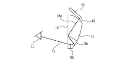
- Fig. 1 shows the configuration of an image display device according to a first embodiment.
- An image display element 10 is disposed in front of the left eye EL of an observer P, and an optical element that is a prism body 11 is disposed between the image display element 10 and the left eye EL.
- the same image display element 10 as that on the left eye side is disposed in front of the right eye ER of the observer P, and an optical element that is the same prism body 11 as that on the left eye side is disposed between the image display element 10 and the right eye ER. That is, the optical elements are a left eye member and a right eye member.
- the image display elements 10 and the prism bodies 11 are collectively referred to as eyepiece optical system.
- the prism bodies 11 have a part shape such that nose side parts 12 and 13 are removed.
- the nose side parts 12 and 13 are removed for the purpose of avoiding interference (contact) between the nose N of the observer P and the left and right prism bodies 11.
- the prism bodies 11 in this embodiment have a bilaterally symmetrical shape. Because of a bilaterally symmetrical shape, the left and right prism bodies 11 can be manufactured in the same manufacturing process, and the manufacturing cost can be reduced.
- Fig. 2 shows part of a principal ray passing through the prism body in the first embodiment.
- the prism body 11 mainly has three large surfaces: an A surface 14, a B surface 15, and a C surface 16.
- An image emitted from the image display element 10 passes through the inside of the prism body 11, and is reflected twice by the A surface 14 and the B surface 15, and the image of the image display element 10 is thereby enlarged.
- the principal ray 18 is emitted from the lower right corner of the display surface of the image display element 10.
- the principal ray 18 enters through the C surface 16.
- the principal ray at this time is denoted by 18a.
- the principal ray 18a travels to the A surface 14.
- the principal ray 18a is at a shallow angle to the A surface 14, the principal ray 18a is totally reflected by the A surface 14.
- the principal ray 18a becomes a principal ray 18b, and reaches the B surface 15.
- an aluminum vapor-deposited film is formed on the B surface 15, the principal ray 18b is reflected by the B surface 15.
- the principal ray 18b becomes a principal ray 18c, exits through the A surface 14, and is guided to the eye of the observer.
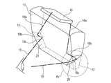
- Fig. 3 shows the shape of the prism body in this embodiment.
- the surface 20 is a surface that forms part of the nose side part 13, and is a nose side removal surface.
- the direction of the principal ray 18c is parallel to the nose side removal surface 20, and the principal ray 18c is located on the nose side removal surface 20.
- the nose side removal surface 20 is painted black. This is for the purpose of blocking unwanted rays from entering through the nose side removal surface 20, and preventing image quality deterioration such as flare and ghost images due to internal reflection in the prism body 11 on the nose side removal surface 20.
- an optical thin film such as an aluminum vapor-deposited film or an antireflection film may be formed for the same purpose.
- the principal ray 19 is emitted from the lower left corner of the display surface of the image display element 10. Since the prism body 11 has a bilaterally symmetrical shape, the principal ray 19 is guided to the eye of the observer through an optical path symmetrical to the optical path of the principal ray 18.
- the surface 21 is a surface that forms part of the nose side part 12, and is a nose side removal surface.
- the principal ray 19c is parallel to the nose side removal surface 21, and the principal ray 19c is located on the nose side removal surface 21.
- the nose side removal surface 21 is painted black to prevent ghost images due to internal reflection of unwanted rays and to block light from entering from the outside of the effective optical path.
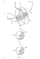
- Fig. 4 shows the vignetting of an effective bundle of rays forming a principal ray in this embodiment.
- the effective bundle of rays 18d is an effective bundle of rays of the principal ray 18c, and planes (cross-sections) perpendicular to the principal ray 18c are shown.
- the hatched region on the right side of the nose side removal surface 20 shows part of the bundle of rays being vignetted by the nose side removal surface 20. Since the principal ray 18c is located on the nose side removal surface 20, in the section A-A, the vignetted area is a half of the area of the effective bundle of rays.
- the hatched region on the right side of the nose side removal surface 20 shows part of the bundle of rays being vignetted by the nose side removal surface 20.
- the vignetted area is a half of the area of the effective bundle of rays. That is, the vignetting of the effective bundle of rays 18d forming the principal ray 18c is a half at any cross-section, and when the principal ray is parallel to the nose side removal surface 20, the amount of vignetting is the same at any cross-section. Therefore, when the principal ray is parallel to the nose side removal surface, the nose side removal surface is the most efficient as a removal surface.
- the prism body 11 Since the prism body 11 has a bilaterally symmetrical shape, part of the effective bundle of rays including the principal ray 19 is vignetted by the nose side removal surface 21 also in the nose side part 12 on the left side of the prism body 11.
- the rate of vignetting is a half of the effective light beam consisting the principal ray 19c, and the amount of vignetting of the effective bundle of rays forming the principal ray 19c is the same at any cross-section.
- prism bodies 11 are disposed at positions corresponding to both left and right eyes.
- parts of the prism bodies 11 that are near the nose are removed at the nose side removal surfaces 20 and 21 such that the principal rays 18c and 19c nearest to the nose side removal surfaces 20 and 21 are parallel to the nose side removal surface 20 and 21.
- a display optical system can be achieved in which prism bodies 11 are unlikely to interfere with the nose of an observer, and the decrease in the amount of light of the observed display image is minimized.
- the present invention is not limited to complete parallelism.
- a case in which the angle between the principal ray 18c and the nose side removal surface 20 is 5 degrees is within the range of "substantially parallel" in this embodiment.
- the angle between the principal ray 18c and the nose side removal surface 20 is 5 degrees
- the maximum thickness of the prism body 11 near the left and right nose side removal surfaces 20 and 21 is 5 mm.
- a margin of an optical effective bundle of rays of 0.5 mm is generally allowed, and 0.437 mm is within this range. Therefore, the influence of the decrease in the amount of light of the observed image is small.
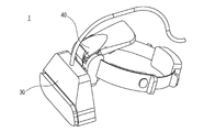
- Fig. 5 shows the configuration of a head mounted image display device.
- the display optical system described in the first embodiment is applied to a head mounted image display device 1.
- the head mounted image display device 1 includes an image display portion 30 having a display optical system therein, and a mounting portion 40 mounted on the head.
- Fig. 6 shows the configuration of a handheld image display device.
- the display optical system described in the first embodiment is applied to a handheld image display device 2.
- the handheld image display device 2 includes an image display portion 30 having a display optical system therein, and a handheld portion 50 held by the hands of an observer.
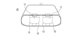
- Figs. 7A to 7C show the image display portion 30.
- Fig. 7A is a front view
- Fig. 7B is a right side view
- Fig. 7C is a back view.
- the prism bodies 11 are disposed observably by both left and right eyes, and are surrounded by an exterior member.
- the central part of the image display portion 30 is recessed, and an exterior nose avoiding portion 30b that does not interfere with the nose of the observer is formed.
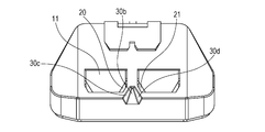
- Fig. 8 shows the lower back of the image display portion.
- the exterior nose avoiding portion 30b is provided with an exterior nose avoiding surface 30c and an exterior nose avoiding surface 30d.
- the exterior nose avoiding surface 30c is parallel to the nose side removal surface 20 of the prism body 11 on the left eye side
- the exterior nose avoiding surface 30d is parallel to the nose side removal surface 21 of the prism body 11 on the right eye side. Therefore, the exterior nose avoiding portion 30b can be large such that it touches the prism bodies 11, and the exterior nose avoiding portion 30b can be maximized without interfering with the prism bodies 11.
Abstract
La présente invention a trait à un dispositif d'affichage d'image qui comprend des éléments optiques, à savoir un élément pour œil gauche (11) et un élément pour œil droit. Le dispositif d'affichage d'image possède un élément d'affichage d'image (10) qui affiche une image destinée à un observateur par l'intermédiaire de l'élément pour œil gauche (11) et de l'élément pour œil droit. L'élément pour œil gauche (11) et l'élément pour œil droit ont chacun au moins une forme de pièce (20) conçue de manière à éviter le contact avec le nez de l'observateur. La surface de ladite forme de pièce (20) est sensiblement parallèle à la direction d'un rayon principal (18c) provenant de l'élément d'affichage d'image (10).
Priority Applications (1)
| Application Number | Priority Date | Filing Date | Title |
|---|---|---|---|
| US15/747,056 US20180364484A1 (en) | 2015-07-24 | 2016-07-15 | Image display device and optical element |
Applications Claiming Priority (2)
| Application Number | Priority Date | Filing Date | Title |
|---|---|---|---|
| JP2015146837A JP2017026898A (ja) | 2015-07-24 | 2015-07-24 | 画像表示装置および光学素子 |
| JP2015-146837 | 2015-07-24 |
Publications (1)
| Publication Number | Publication Date |
|---|---|
| WO2017017924A1 true WO2017017924A1 (fr) | 2017-02-02 |
Family
ID=57884181
Family Applications (1)
| Application Number | Title | Priority Date | Filing Date |
|---|---|---|---|
| PCT/JP2016/003354 WO2017017924A1 (fr) | 2015-07-24 | 2016-07-15 | Dispositif d'affichage d'image et élément optique |
Country Status (3)
| Country | Link |
|---|---|
| US (1) | US20180364484A1 (fr) |
| JP (1) | JP2017026898A (fr) |
| WO (1) | WO2017017924A1 (fr) |
Cited By (1)
| Publication number | Priority date | Publication date | Assignee | Title |
|---|---|---|---|---|
| WO2020040813A1 (fr) * | 2018-08-23 | 2020-02-27 | Apple Inc. | Dispositif électronique à détection de position de lentille |
Citations (8)
| Publication number | Priority date | Publication date | Assignee | Title |
|---|---|---|---|---|
| JPH06326946A (ja) * | 1993-05-13 | 1994-11-25 | Agency Of Ind Science & Technol | 眼球運動追従型視覚提示装置 |
| WO2000020951A2 (fr) * | 1998-10-02 | 2000-04-13 | Honeywell Inc. | Ordinateur portatif a visionneuse d'affichage |
| US6384983B1 (en) * | 1999-11-19 | 2002-05-07 | Mixed Realty Systems Laboratory Inc. | Image display apparatus |
| JP2005049690A (ja) * | 2003-07-30 | 2005-02-24 | Canon Inc | 画像表示光学系 |
| JP2007127782A (ja) * | 2005-11-02 | 2007-05-24 | Konica Minolta Photo Imaging Inc | 画像表示装置、表示システム |
| US20090153960A1 (en) * | 2007-12-14 | 2009-06-18 | Canon Kabushiki Kaisha | Image display apparatus |
| JP2013025102A (ja) * | 2011-07-21 | 2013-02-04 | Olympus Corp | 画像表示装置 |
| JP2014225823A (ja) * | 2013-05-17 | 2014-12-04 | セイコーエプソン株式会社 | 虚像表示装置 |
Family Cites Families (10)
| Publication number | Priority date | Publication date | Assignee | Title |
|---|---|---|---|---|
| JP2000098293A (ja) * | 1998-06-19 | 2000-04-07 | Canon Inc | 画像観察装置 |
| JP3730806B2 (ja) * | 1999-05-18 | 2006-01-05 | オリンパス株式会社 | 光学系 |
| JP2001186442A (ja) * | 1999-12-27 | 2001-07-06 | Minolta Co Ltd | 映像表示装置 |
| JP2001209000A (ja) * | 2000-01-24 | 2001-08-03 | Minolta Co Ltd | 映像表示装置 |
| JP2001281593A (ja) * | 2000-03-29 | 2001-10-10 | Olympus Optical Co Ltd | 頭部装着型映像表示装置 |
| JP2002258208A (ja) * | 2001-03-01 | 2002-09-11 | Mixed Reality Systems Laboratory Inc | 光学素子及びそれを用いた複合表示装置 |
| JP4825244B2 (ja) * | 2008-06-26 | 2011-11-30 | オリンパス株式会社 | 立体視画像表示装置、立体視画像表示方法 |
| JP5266526B2 (ja) * | 2008-10-15 | 2013-08-21 | コニカミノルタ株式会社 | 映像表示装置 |
| JP6135095B2 (ja) * | 2012-11-05 | 2017-05-31 | セイコーエプソン株式会社 | 虚像表示装置 |
| RU2017105422A (ru) * | 2014-07-22 | 2018-08-26 | Навди Инк. | Компактная система индикации на лобовом стекле |
-
2015
- 2015-07-24 JP JP2015146837A patent/JP2017026898A/ja active Pending
-
2016
- 2016-07-15 WO PCT/JP2016/003354 patent/WO2017017924A1/fr active Application Filing
- 2016-07-15 US US15/747,056 patent/US20180364484A1/en not_active Abandoned
Patent Citations (8)
| Publication number | Priority date | Publication date | Assignee | Title |
|---|---|---|---|---|
| JPH06326946A (ja) * | 1993-05-13 | 1994-11-25 | Agency Of Ind Science & Technol | 眼球運動追従型視覚提示装置 |
| WO2000020951A2 (fr) * | 1998-10-02 | 2000-04-13 | Honeywell Inc. | Ordinateur portatif a visionneuse d'affichage |
| US6384983B1 (en) * | 1999-11-19 | 2002-05-07 | Mixed Realty Systems Laboratory Inc. | Image display apparatus |
| JP2005049690A (ja) * | 2003-07-30 | 2005-02-24 | Canon Inc | 画像表示光学系 |
| JP2007127782A (ja) * | 2005-11-02 | 2007-05-24 | Konica Minolta Photo Imaging Inc | 画像表示装置、表示システム |
| US20090153960A1 (en) * | 2007-12-14 | 2009-06-18 | Canon Kabushiki Kaisha | Image display apparatus |
| JP2013025102A (ja) * | 2011-07-21 | 2013-02-04 | Olympus Corp | 画像表示装置 |
| JP2014225823A (ja) * | 2013-05-17 | 2014-12-04 | セイコーエプソン株式会社 | 虚像表示装置 |
Cited By (4)
| Publication number | Priority date | Publication date | Assignee | Title |
|---|---|---|---|---|
| WO2020040813A1 (fr) * | 2018-08-23 | 2020-02-27 | Apple Inc. | Dispositif électronique à détection de position de lentille |
| US10823970B2 (en) | 2018-08-23 | 2020-11-03 | Apple Inc. | Head-mounted electronic display device with lens position sensing |
| US11126004B2 (en) | 2018-08-23 | 2021-09-21 | Apple Inc. | Head-mounted electronic display device with lens position sensing |
| US11726338B2 (en) | 2018-08-23 | 2023-08-15 | Apple Inc. | Head-mounted electronic display device with lens position sensing |
Also Published As
| Publication number | Publication date |
|---|---|
| US20180364484A1 (en) | 2018-12-20 |
| JP2017026898A (ja) | 2017-02-02 |
Similar Documents
| Publication | Publication Date | Title |
|---|---|---|
| US9116342B2 (en) | Virtual image display apparatus | |
| US9979936B2 (en) | Virtual image display apparatus | |
| US10247945B2 (en) | Virtual image display apparatus | |
| US9726892B2 (en) | Light guide prism and image display apparatus | |
| US9568731B2 (en) | Virtual image display device | |
| US20120242561A1 (en) | Head-Mounted Display Device | |
| JP2014174429A (ja) | 虚像表示装置 | |
| US10168454B2 (en) | Head-mounted display device | |
| US10073273B2 (en) | Virtual image display apparatus | |
| KR101590825B1 (ko) | 헤드 마운티드 디스플레이 장치용 복합 렌즈 및 이를 포함하는 디스플레이 장치 | |
| US20150293361A1 (en) | Head-mounted display device | |
| JP6036160B2 (ja) | 光学デバイス及び画像表示装置 | |
| JP2017120384A (ja) | 虚像表示装置 | |
| US10261322B2 (en) | Virtual image display apparatus | |
| WO2017017924A1 (fr) | Dispositif d'affichage d'image et élément optique | |
| US10295829B2 (en) | Optical element and display device | |
| US11099395B2 (en) | Virtual image display device | |
| US10394028B2 (en) | Virtual image display apparatus | |
| US11630305B2 (en) | Attachable image display device and ocular optical system | |
| JP2015179200A (ja) | 虚像観察光学系及び虚像観察装置 | |
| JP6293773B2 (ja) | 導光プリズム | |
| JP6380620B2 (ja) | 虚像表示装置 | |
| WO2020026813A1 (fr) | Dispositif d'affichage | |
| US20220397758A1 (en) | Optical device and display device | |
| JP6238801B2 (ja) | 虚像観察光学系及び虚像観察装置 |
Legal Events
| Date | Code | Title | Description |
|---|---|---|---|
| 121 | Ep: the epo has been informed by wipo that ep was designated in this application |
Ref document number: 16830032 Country of ref document: EP Kind code of ref document: A1 |
|
| NENP | Non-entry into the national phase |
Ref country code: DE |
|
| 122 | Ep: pct application non-entry in european phase |
Ref document number: 16830032 Country of ref document: EP Kind code of ref document: A1 |