WO2017017779A1 - ケーブル及び可動部配線用フラットケーブル - Google Patents
ケーブル及び可動部配線用フラットケーブル Download PDFInfo
- Publication number
- WO2017017779A1 WO2017017779A1 PCT/JP2015/071334 JP2015071334W WO2017017779A1 WO 2017017779 A1 WO2017017779 A1 WO 2017017779A1 JP 2015071334 W JP2015071334 W JP 2015071334W WO 2017017779 A1 WO2017017779 A1 WO 2017017779A1
- Authority
- WO
- WIPO (PCT)
- Prior art keywords
- cable
- metal
- flexible tube
- tube
- flexible
- Prior art date
- Legal status (The legal status is an assumption and is not a legal conclusion. Google has not performed a legal analysis and makes no representation as to the accuracy of the status listed.)
- Ceased
Links
Images


Classifications
-
- H—ELECTRICITY
- H01—ELECTRIC ELEMENTS
- H01B—CABLES; CONDUCTORS; INSULATORS; SELECTION OF MATERIALS FOR THEIR CONDUCTIVE, INSULATING OR DIELECTRIC PROPERTIES
- H01B7/00—Insulated conductors or cables characterised by their form
- H01B7/08—Flat or ribbon cables
-
- H—ELECTRICITY
- H01—ELECTRIC ELEMENTS
- H01B—CABLES; CONDUCTORS; INSULATORS; SELECTION OF MATERIALS FOR THEIR CONDUCTIVE, INSULATING OR DIELECTRIC PROPERTIES
- H01B7/00—Insulated conductors or cables characterised by their form
- H01B7/17—Protection against damage caused by external factors, e.g. sheaths or armouring
- H01B7/18—Protection against damage caused by wear, mechanical force or pressure; Sheaths; Armouring
- H01B7/20—Metal tubes, e.g. lead sheaths
Definitions
- the present invention relates to a cable and a flat cable for wiring a movable part.
- the movable part wiring cable is required to have excellent flexibility so that it does not break even if it is repeatedly subjected to U-bending. Therefore, polyvinyl chloride (PVC) has excellent flexibility as a sheath material. Resin or the like is used.
- the polyvinyl chloride resin or the like constituting the sheath has excellent flexibility, if the cable is subjected to U-shaped bending under such severe conditions, the cable may not be kept straight but bend and bend. is there.
- an object of the present invention is to provide a cable that is less likely to be entangled even when subjected to a U-shaped bend at high speed, and that can suppress wear of the cable sheath and accompanying dust generation, and a flat cable for movable part wiring using the cable. There is to do.
- the present invention provides the following cable and a flat cable for wiring a movable part.
- a cable core including a conductor and an insulator covering the conductor, and one or more metal or resin bellows-like flexible tubes disposed along the longitudinal direction of the cable core.
- cable [2] The first flexible tube of the flexible tubes is disposed at the center of the cross section of the cable, and a plurality of cable cores are provided on the outer periphery of the first flexible tube.
- the cable core is disposed in a second flexible tube of the flexible tubes, and the second flexible tube is not the outermost layer. The cable according to any one of [3].
- the present invention it is possible to provide a cable that is less likely to be entangled even when subjected to U-bending at a high speed, and that can suppress wear of the cable sheath and dust generation associated therewith, and a flat cable for movable part wiring using the cable. Can do.
- a cable according to an embodiment of the present invention includes a cable core including a conductor and an insulator covering the conductor, and one or more metal or resin bellows arranged along the longitudinal direction of the cable core.
- Flexible tube There may be one cable core or a plurality of cable cores.
- the bellows-like flexible tube in the embodiment of the present invention does not expand even when pulled in the longitudinal direction.
- a force for contracting in the longitudinal direction is applied, it contracts by about 3 to 10%, but when the force is released.
- a tube made of metal or resin that returns to its original length has flexibility but does not bend more than a certain amount, and has restoring force (straightness). If it is a flexible pipe
- FIG. 1 is a cross-sectional view showing the structure of a cable according to the first embodiment of the present invention.
- the cable 10 according to the first embodiment of the present invention has a single metal bellows-like flexible tube 11 (hereinafter referred to as a metal tube) as the first flexible tube.
- the metal tube 11 is disposed at the center of the cross section of the cable 10, and a plurality of cable cores 13 are disposed on the outer periphery of the metal tube 11.
- the cable 10 has a substantially circular cross-sectional shape, and includes a plurality of cable cores 13 including a metal tube 11 provided with a resin coating layer 12, and a conductor 13a and an insulator 13b that covers the conductor 13a disposed on the outer periphery thereof. 1 (6 in FIG. 1), a binding tape 14 made of polytetrafluoroethylene (PTFE) or the like wound around the outer periphery to bundle them, and a metal wire such as a silver-plated copper wire provided around the binding tape 14 Is formed of a metal braided shield 15 formed by braiding and a sheath 16 made of PVC or the like coated on the periphery thereof.
- PTFE polytetrafluoroethylene
- the metal tube 11 may be left as it is, but it is preferable that the resin coating layer 12 is provided so as not to damage the insulator 13b of the cable core 13.
- the resin coating layer 12 is preferably solid-extruded (material: polyvinyl chloride resin (PVC), polyurethane, etc.) on the outer periphery of the metal tube 11. Further, instead of full extrusion, a bind tape (material: PVC, polyurethane, etc.) may be wound. If the flexible tube is a resin tube, the resin coating layer 12 may not be provided.
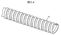
- FIG. 2A is a perspective view showing a structure of a metal tube (flexible tube) used in the cable according to the embodiment of the present invention.
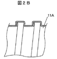
- 2B is a cross-sectional view showing an example of the metal tube expansion and contraction structure of FIG. 2A
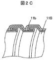
- FIG. 2C is a cross-sectional view showing an example different from FIG.
- the metal tube 11 has a bellows shape, and when the force is applied so that the convex portions adjacent to each other in the longitudinal direction approach each other, the tube contracts in the longitudinal direction and automatically releases if the force is released.
- the tube extends to its original length. Since the metal tube 11 does not bend more than a certain amount and has a restoring force (straight advance) even if it is bent, the cable 10 as a whole is prevented from being bent more than a certain amount, and the cable becomes strong. As a result, the cable can be prevented from dripping even if it is subjected to U-shaped bending at high speed, so that the cable is less likely to be entangled, and cable abrasion and accompanying dust generation can be suppressed.
- the expansion / contraction structure of the metal tube 11 is not particularly limited.
- a so-called Squarelock structure such as the metal tube 11A illustrated in FIG. 2B or the metal tube 11B illustrated in FIG. 2C is used.
- Such a so-called Interlock structure double lock structure is preferable. Interlock structure is more preferable in terms of smoothness and strength of appearance.
- the coating layer 11b which consists of resin, such as PVC, is provided as FIG. 2C shows.
- the metal tube 11 is preferably made of a copper alloy, stainless steel, or aluminum alloy. Plating treatment such as zinc plating or tin plating may be performed.
- the size of the metal tube 11 is preferably, for example, an inner diameter of 4 ⁇ 0.5 mm and an outer diameter of 6 ⁇ 0.5 mm.
- the cable core 13 includes a center conductor 13a and an insulator 13b that is coated or wound around the outer periphery of the center conductor 13a. Interpositions, external conductors, and the like may be provided.
- the conductor 13a may be a single wire or a stranded wire.
- the conductor 13a is made of, for example, a copper alloy, and may be plated with silver plating or the like.
- the size of the conductor 13a is not particularly limited. For example, a conductor having a thickness of 28-14 AWG (American Wire Gauge) is preferably used.
- the number of cable cores 13 is six in FIG. 1, but is not particularly limited, and is preferably 4 to 10, for example.
- the insulator 13b is formed by, for example, extrusion molding a resin selected from a fluororesin, polyethylene (PE), and polypropylene (PP).
- the thickness of the insulator 13b is, for example, 0.15 to 0.4 mm.
- the insulator 13b is not limited to a single layer, and may be two or more layers.
- the bind tape 14 is, for example, a tape made of a resin such as a paper tape having good slipperiness, polytetrafluoroethylene (PTFE), nylon resin, polyethylene terephthalate (PET) resin, and a part of the adjacent tapes when wound. It is wrapped so that it can be overlaid.
- a resin such as a paper tape having good slipperiness, polytetrafluoroethylene (PTFE), nylon resin, polyethylene terephthalate (PET) resin, and a part of the adjacent tapes when wound. It is wrapped so that it can be overlaid.
- the metal braided shield 15 is preferably formed by weaving flat wire having a substantially rectangular cross section. In order to avoid damage to the binding tape 14 and the sheath 16, it is desirable to use a rounded strand, and a flat strand formed by rolling a strand having a circular cross section is used. desirable.
- the thickness of the flat wire is preferably about 0.1 to 0.15 mm, and the width of the flat wire is preferably about 0.5 to 2 mm.
- the sheath 16 is formed, for example, by extruding a resin selected from polyvinyl chloride resin, polyurethane resin, polyolefin resin, and fluororesin.
- the thickness of the sheath 16 is, for example, 0.8 to 1.5 mm.
- the sheath 16 is not limited to a single layer, and may be two or more layers.
- the cable 10 according to the present embodiment is suitable as a movable part wiring cable used in a semiconductor or liquid crystal screen production line or the like, but is not limited to this, and is not limited to a medical cable (probe cable or the like) or a vehicle. It can be used for various purposes such as cables for industrial use.
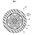
- FIG. 3 is a cross-sectional view showing the structure of the cable according to the second embodiment of the present invention.
- the cable 20 according to the second embodiment of the present invention has a single metal tube 21 as a second flexible tube.
- the metal tube 21 is disposed outside the cable core 13. That is, the cable core 13 is disposed in the pipe of the metal pipe 21.
- the configuration of the cable 20 shown in FIG. 3 will be described in more detail.
- the cable 20 has a substantially circular cross section, and includes an interposer 22 made of aramid fibers or the like disposed at the center of the cross section of the cable, and a conductor 13a and an insulator 13b covering the conductor 13a disposed on the outer periphery thereof.
- a bind tape 14 made of polytetrafluoroethylene (PTFE) or the like wound around the outer periphery in order to bundle them, and to accommodate these in the pipe
- the metal tube 21 is provided and a sheath 16 made of PVC or the like coated around the metal tube 21. Since the configurations denoted by the same reference numerals as those in the first embodiment are the same as those in the first embodiment, description thereof will be omitted.
- the metal tube 21 may be provided with a resin coating layer 12 formed by fully extruding a resin such as PVC or winding a bind tape.
- the metal tube 21 is a bellows-like flexible metal tube having the same characteristics as the metal tube 11 in the first embodiment described above, but the size is larger than that of the metal tube 11 in the first embodiment.
- those having an inner diameter of 6 ⁇ 0.5 mm and an outer diameter of 8 ⁇ 0.5 mm are suitable.
- the metal braided shield 15 in the first embodiment is not provided. This is because the metal tube 21 also functions as a shield. Since there is no gap on the outer surface of the metal tube 21, the shielding performance is improved compared to the braid.
- a metal braided shield 15 may be provided, and in this case, it is preferable to provide it between the bind tape 14 and the metal tube 21.
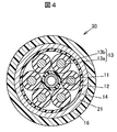
- FIG. 4 is a cross-sectional view showing the structure of the cable according to the third embodiment of the present invention.
- the cable 30 according to the third embodiment of the present invention is a fusion type of the first embodiment and the second embodiment described above, and the metal braid shield in the cable 10 according to the first embodiment. 15 is replaced with the metal tube 21 in the cable 20 according to the second embodiment. That is, the cable 30 includes two bellows-like flexible metal tubes 11 and 21 (first and second flexible tubes).
- the first and second embodiments are superior, but the effect of the present invention that suppresses cable entanglement is more easily exhibited by the present embodiment.
- the movable part wiring flat cable according to the embodiment of the present invention is formed by arranging a plurality of the cables according to the embodiment of the present invention in parallel and connecting sheaths of adjacent cables.
- FIG. 5 is a cross-sectional view showing the structure of the movable part wiring flat cable according to the embodiment of the present invention.
- a plurality of the cables 10 according to the first embodiment of the present invention are arranged in parallel, and the sheaths of adjacent cables 10 are connected. It has been made.
- the sheaths can be connected by fusion, bonding, or the like.
- the connected sheaths may be collectively formed by extrusion coating or the like.
- the number of cables to be connected in parallel is not limited to five, and for example, 3 to 15 cables are suitable.
- the cables according to the second to fourth embodiments may be used instead of the cable 10 according to the first embodiment, and two or more of these cables may be used in parallel.
- the metal braiding can be omitted, there is a problem that the sheath is broken (exposure of the braided wire) due to the breakage of the metal braiding strand and the insulator is cut and short-circuited. Can be resolved.
- the use of the cable bear can be omitted because the cable according to the embodiment of the present invention is used.
Landscapes
- Insulated Conductors (AREA)
Abstract
高速でU字屈曲を受けてもケーブルが絡みにくく、ケーブルシースの摩耗とこれに伴う発塵を抑制できるケーブル及び当該ケーブルを使用した可動部配線用フラットケーブルを提供する。 ケーブル10は、導体13a及び導体13aを被覆する絶縁体13bを含むケーブルコア13と、ケーブルコア13の長手方向に沿って配置された1本以上の金属製又は樹脂製の蛇腹状の可撓性管とを有する。
Description
本発明は、ケーブル及び可動部配線用フラットケーブルに関する。
半導体や液晶画面の製造ライン等で用いられるケーブルのうち、U字屈曲を繰り返し受ける可動部に配線される可動部配線用ケーブルは、断線や捩れ対策のためにケーブルベアの中に纏められている(例えば特許文献1及び2参照)。
可動部配線用ケーブルには、U字屈曲を繰り返し受けても断線しないように優れた可撓性が要求されることから、シースの材質として、優れた柔軟性を有する、ポリ塩化ビニル(PVC)樹脂等が用いられている。
また、半導体等の製造ラインでは、発塵(粉塵の発生)は部品不良を誘発する原因となるので、シースを構成するポリ塩化ビニル樹脂等の配合として、シースとケーブルベアとの接触による発塵を抑制することが可能なIPAクリーンクラス証明を取得したものを採用している。
一方、ケーブルベアを用いると、上記の通り、シースとケーブルベアとの接触による発塵などの問題があることから、ケーブルベアを使用しないで済むケーブルベアレス平型構造ケーブルの開発がなされている(特許文献3参照)。
近年は半導体等の製造ラインの稼働率が年々上昇してきており、製造ラインにおける搬送機械等の高速化が求められている。搬送機械等の高速化に伴い、可動部配線用ケーブルは、U字屈曲をより高速に、かつ激しく、長距離に亘って受けることになる。
しかしながら、シースを構成するポリ塩化ビニル樹脂等は優れた柔軟性を有するため、このような過酷条件下でU字屈曲を受けるとケーブルが直進性を保つことができずに垂れて屈曲しまうことがある。
ケーブルが垂れて屈曲してしまうと、ケーブル同士が絡みやすくなり、シース同士の接触により摩耗し発塵が増加する。また、ケーブルとケーブルベアとが接触し易くなり、たとえIPAクリーンクラス証明を取得した配合を採用した場合であっても、ケーブルシースの摩耗とこれに伴う発塵が増加する。これらが製造ラインにおいて部品不良の問題を引き起こす原因となる。
そこで、本発明の目的は、高速でU字屈曲を受けてもケーブルが絡みにくく、ケーブルシースの摩耗とこれに伴う発塵を抑制できるケーブル及び当該ケーブルを使用した可動部配線用フラットケーブルを提供することにある。
本発明は、上記目的を達成するために、下記のケーブル及び可動部配線用フラットケーブルを提供する。
[1]導体及び前記導体を被覆する絶縁体を含むケーブルコアと、前記ケーブルコアの長手方向に沿って配置された1本以上の金属製又は樹脂製の蛇腹状の可撓性管とを有するケーブル。
[2]前記可撓性管のうちの第1の可撓性管は、前記ケーブルの横断面中心に配置されており、前記ケーブルコアは、前記第1の可撓性管の外周に複数本、配置されている前記[1]に記載のケーブル。
[3]前記第1の可撓性管は、金属製である前記[2]に記載のケーブル。
[4]前記ケーブルコアは、前記可撓性管のうちの第2の可撓性管の管内に配置されており、前記第2の可撓性管は、最外層ではない前記[1]~[3]のいずれか1つに記載のケーブル。
[5]前記第2の可撓性管は、金属製であり、前記ケーブルは、金属編組を有していない前記[4]に記載のケーブル。
[6]前記可撓性管のうちの第3の可撓性管は、樹脂製であり、シースを構成している前記[1]~[5]のいずれか1つに記載のケーブル。
[7]前記[1]~[6]のいずれか1つに記載のケーブルが複数本並列に並べられ、隣接するケーブルのシースを連結させた可動部配線用フラットケーブル。
[2]前記可撓性管のうちの第1の可撓性管は、前記ケーブルの横断面中心に配置されており、前記ケーブルコアは、前記第1の可撓性管の外周に複数本、配置されている前記[1]に記載のケーブル。
[3]前記第1の可撓性管は、金属製である前記[2]に記載のケーブル。
[4]前記ケーブルコアは、前記可撓性管のうちの第2の可撓性管の管内に配置されており、前記第2の可撓性管は、最外層ではない前記[1]~[3]のいずれか1つに記載のケーブル。
[5]前記第2の可撓性管は、金属製であり、前記ケーブルは、金属編組を有していない前記[4]に記載のケーブル。
[6]前記可撓性管のうちの第3の可撓性管は、樹脂製であり、シースを構成している前記[1]~[5]のいずれか1つに記載のケーブル。
[7]前記[1]~[6]のいずれか1つに記載のケーブルが複数本並列に並べられ、隣接するケーブルのシースを連結させた可動部配線用フラットケーブル。
本発明によれば、高速でU字屈曲を受けてもケーブルが絡みにくく、ケーブルシースの摩耗とこれに伴う発塵を抑制できるケーブル及び当該ケーブルを使用した可動部配線用フラットケーブルを提供することができる。
〔ケーブル〕
本発明の実施の形態に係るケーブルは、導体及び前記導体を被覆する絶縁体を含むケーブルコアと、前記ケーブルコアの長手方向に沿って配置された1本以上の金属製又は樹脂製の蛇腹状の可撓性管とを有する。ケーブルコアは、1本であっても複数本であってもよい。
本発明の実施の形態に係るケーブルは、導体及び前記導体を被覆する絶縁体を含むケーブルコアと、前記ケーブルコアの長手方向に沿って配置された1本以上の金属製又は樹脂製の蛇腹状の可撓性管とを有する。ケーブルコアは、1本であっても複数本であってもよい。
ここで、本発明の実施の形態における蛇腹状の可撓性管とは、長手方向に引っ張っても伸びない、長手方向に収縮させる力を加えると3~10%程度収縮するが力を解放すると元の長さに戻る、可撓性を有するが一定以上は曲がらない、及び復元力(直進性)がある金属製又は樹脂製の管をいう。このような特性を有する可撓性管であれば、特に限定されることなく市販の製品を使用することができる。
以下、金属製の可撓性管を例に各実施形態を説明するが、同様の特性を有するPVC等からなる樹脂製の可撓性管であってもよい。
(第1の実施の形態)
図1は、本発明の第1の実施の形態に係るケーブルの構造を示す横断面図である。
本発明の第1の実施の形態に係るケーブル10は、第1の可撓性管として1本の金属製の蛇腹状の可撓性管11(以下、金属管という)を有している。金属管11は、ケーブル10の横断面中心に配置されており、ケーブルコア13が金属管11の外周に複数本、配置されている。
図1は、本発明の第1の実施の形態に係るケーブルの構造を示す横断面図である。
本発明の第1の実施の形態に係るケーブル10は、第1の可撓性管として1本の金属製の蛇腹状の可撓性管11(以下、金属管という)を有している。金属管11は、ケーブル10の横断面中心に配置されており、ケーブルコア13が金属管11の外周に複数本、配置されている。
図1に示すケーブル10の構成をより詳細に説明する。
ケーブル10は、断面略円形の形状を有し、樹脂被覆層12が設けられた金属管11と、その外周に配置された、導体13a及び導体13aを被覆する絶縁体13bを含むケーブルコア13複数本(図1では6本)と、これらを束ねるためにその外周に巻き付けられたポリテトラフルオロエチレン(PTFE)等からなるバインドテープ14と、その周囲に設けられた銀めっき銅線などの金属線を編組してなる金属編組シールド15と、その周囲に被覆されたPVC等からなるシース16とから構成されている。
ケーブル10は、断面略円形の形状を有し、樹脂被覆層12が設けられた金属管11と、その外周に配置された、導体13a及び導体13aを被覆する絶縁体13bを含むケーブルコア13複数本(図1では6本)と、これらを束ねるためにその外周に巻き付けられたポリテトラフルオロエチレン(PTFE)等からなるバインドテープ14と、その周囲に設けられた銀めっき銅線などの金属線を編組してなる金属編組シールド15と、その周囲に被覆されたPVC等からなるシース16とから構成されている。
金属管11は、そのままでもよいが、ケーブルコア13の絶縁体13bを傷付けないために樹脂被覆層12が設けられていることが好ましい。樹脂被覆層12は、金属管11の外周に充実押出(材質:ポリ塩化ビニル樹脂(PVC)やポリウレタン等)されていることが好ましい。また、充実押出に換えて、バインドテープ(材質:PVCやポリウレタン等)を巻き付けるようにしてもよい。なお、可撓性管が樹脂製の管である場合には、樹脂被覆層12を設けなくてもよい。
図2Aは、本発明の実施の形態に係るケーブルに使用される金属管(可撓性管)の構造を示す斜視図である。図2Bは、図2Aの金属管の伸縮構造の一例を示す断面図であり、図2Cは、図2Bとは別の一例を示す断面図である。
金属管11は、図2Aに示されるように蛇腹状であり、長手方向に隣接する凸部同士が近づくように力を加えることで長手方向に管が収縮し、力を解放すれば、自動的に元の長さに管が伸長する。金属管11は、一定以上は曲がらず、曲げても復元力(直進性)があるため、ケーブル10全体としても一定以上曲がることが阻止され、またケーブルの腰が強くなる。これにより、高速でU字屈曲を受けても、ケーブルが垂れないようにすることができるため、ケーブルが絡みにくく、ケーブルの摩耗とこれに伴う発塵を抑制できる
金属管11の伸縮構造は、特に限定されるものではないが、例えば、図2Bに示される金属管11Aのような、いわゆるSquarelock構造(シングルのロック構造)や、図2Cに示される金属管11Bのような、いわゆるInterlock構造(ダブルのロック構造)であることが好ましい。Interlock構造であることが外観の滑らかさや強度の点でより好ましい。また、図2Cに示されるようにPVC等の樹脂からなる被覆層11bが設けられていることが好ましい。
金属管11は、銅合金、ステンレス、又はアルミ合金からなることが好ましい。亜鉛めっきや錫めっき等のメッキ処理が施されていてもよい。また、金属管11のサイズは、例えば、内径4±0.5mm、外径6±0.5mmであるものが好適である。
ケーブルコア13は、中心導体13aと、中心導体13aの外周に被覆又は巻き付けられた絶縁体13bとを有する。介在や外部導体等が設けられていてもよい。
導体13aは、単線でも撚線でもよい。導体13aは、例えば銅合金からなり、銀めっき等のめっきが施されていてもよい。導体13aのサイズは特に限定されるものではないが、例えば28~14AWG(American Wire Gauge)のものが好適に使用される。
ケーブルコア13の本数は、図1では6本としたが、特に限定されるものではなく、例えば、4~10本であることが好ましい。
絶縁体13bは、例えば、フッ素樹脂、ポリエチレン(PE)、ポリプロピレン(PP)から選ばれる樹脂を押出成形することにより形成されたものである。絶縁体13bの厚みは、例えば0.15~0.4mmである。絶縁体13bは、単層に限らず、2層以上としてもよい。
バインドテープ14は、例えば、滑り性の良い紙テープやポリテトラフルオロエチレン(PTFE)、ナイロン樹脂、ポリエチレンテレフタレート(PET)樹脂等の樹脂からなるテープであり、巻き付けたときに隣接するテープ同士が一部で重ね合わされるようにラップ巻きされている。
金属編組シールド15は、断面略矩形状の平角素線を編み込んで形成されることが好ましい。平角素線としては、バインドテープ14やシース16の損傷を避けるために、角を丸めたものを用いることが望ましく、断面円形状の素線を圧延加工して形成した平角素線を用いることが望ましい。平角素線の厚さは、0.1~0.15mm程度とするとよく、また、平角素線の幅は、0.5~2mm程度とするとよい。
シース16は、例えば、ポリ塩化ビニル樹脂、ポリウレタン樹脂、ポリオレフィン樹脂、フッ素樹脂から選ばれる樹脂を押出成形することにより形成されたものである。シース16の厚みは、例えば0.8~1.5mmである。シース16は、単層に限らず、2層以上としてもよい。
本実施の形態に係るケーブル10は、半導体や液晶画面の製造ライン等で用いられる可動部配線用ケーブルとして好適であるが、これに限られるものではなく、医療用ケーブル(プローブケーブル等)や車両用ケーブル等、種々の用途に利用できる。
(第2の実施の形態)
図3は、本発明の第2の実施の形態に係るケーブルの構造を示す横断面図である。
本発明の第2の実施の形態に係るケーブル20は、第2の可撓性管として1本の金属管21を有している。金属管21は、ケーブルコア13よりも外側に配置されている。すなわち、ケーブルコア13は、金属管21の管内に配置されている。
図3は、本発明の第2の実施の形態に係るケーブルの構造を示す横断面図である。
本発明の第2の実施の形態に係るケーブル20は、第2の可撓性管として1本の金属管21を有している。金属管21は、ケーブルコア13よりも外側に配置されている。すなわち、ケーブルコア13は、金属管21の管内に配置されている。
図3に示すケーブル20の構成をより詳細に説明する。
ケーブル20は、断面略円形の形状を有し、ケーブルの横断面中心に配置されたアラミド繊維等からなる介在22と、その外周に配置された、導体13a及び導体13aを被覆する絶縁体13bを含むケーブルコア13複数本(図3では6本)と、これらを束ねるためにその外周に巻き付けられたポリテトラフルオロエチレン(PTFE)等からなるバインドテープ14と、これらをその管内に収容するように設けられた金属管21と、その周囲に被覆されたPVC等からなるシース16とから構成されている。第1の実施の形態と同じ符号を付した構成については第1の実施の形態と同様であるので説明を省略する。
ケーブル20は、断面略円形の形状を有し、ケーブルの横断面中心に配置されたアラミド繊維等からなる介在22と、その外周に配置された、導体13a及び導体13aを被覆する絶縁体13bを含むケーブルコア13複数本(図3では6本)と、これらを束ねるためにその外周に巻き付けられたポリテトラフルオロエチレン(PTFE)等からなるバインドテープ14と、これらをその管内に収容するように設けられた金属管21と、その周囲に被覆されたPVC等からなるシース16とから構成されている。第1の実施の形態と同じ符号を付した構成については第1の実施の形態と同様であるので説明を省略する。
金属管21は、前述の第1の実施の形態における金属管11の場合と同様に、PVC等の樹脂の充実押出又はバインドテープを巻き付けてなる樹脂被覆層12が設けられていてもよい。
金属管21は、前述の第1の実施の形態における金属管11と同様の特性を有する蛇腹状の可撓性金属管であるが、サイズは第1の実施の形態における金属管11よりも大きく、例えば、内径6±0.5mm、外径8±0.5mmであるものが好適である。
本実施の形態においては、前述の第1の実施の形態における金属編組シールド15を設けていない。これは、金属管21がシールドとしての機能も果たしているためである。金属管21には外表面に隙間が無いため、編組に比べシールド性能がアップする。なお、金属編組シールド15を設けてもよく、この場合、バインドテープ14と金属管21の間に設けることが好ましい。
(第3の実施の形態)
図4は、本発明の第3の実施の形態に係るケーブルの構造を示す横断面図である。
本発明の第3の実施の形態に係るケーブル30は、前述の第1の実施の形態と第2の実施の形態の融合タイプであり、第1の実施の形態に係るケーブル10における金属編組シールド15を第2の実施の形態に係るケーブル20における金属管21に置換したものである。すなわち、ケーブル30は、2本の蛇腹状の可撓性金属管11、21(第1及び第2の可撓性管)を有している。
図4は、本発明の第3の実施の形態に係るケーブルの構造を示す横断面図である。
本発明の第3の実施の形態に係るケーブル30は、前述の第1の実施の形態と第2の実施の形態の融合タイプであり、第1の実施の形態に係るケーブル10における金属編組シールド15を第2の実施の形態に係るケーブル20における金属管21に置換したものである。すなわち、ケーブル30は、2本の蛇腹状の可撓性金属管11、21(第1及び第2の可撓性管)を有している。
細径化の観点では、第1及び第2の実施の形態の方が勝るが、ケーブルの絡みを抑制するという本発明の効果は本実施の形態の方がより発揮しやすい。
〔可動部配線用フラットケーブル〕
本発明の実施の形態に係る可動部配線用フラットケーブルは、本発明の実施の形態に係る上記ケーブルが複数本並列に並べられ、隣接するケーブルのシースを連結させたものである。
本発明の実施の形態に係る可動部配線用フラットケーブルは、本発明の実施の形態に係る上記ケーブルが複数本並列に並べられ、隣接するケーブルのシースを連結させたものである。
図5は、本発明の実施の形態に係る可動部配線用フラットケーブルの構造を示す横断面図である。
本発明の実施の形態に係る可動部配線用フラットケーブル100の構成について、以下に詳細に説明する。
本実施形態に係る可動部配線用フラットケーブル100は、本発明の第1の実施の形態に係るケーブル10が複数本(図5では5本)並列に並べられ、隣接するケーブル10のシースを連結させたものである。シースの連結は、融着、接着等により行なうことができる。連結させた形態のシースを押出被覆等により一括して形成してもよい。
並列させるケーブル本数は、5本に限られるものではなく、例えば、3~15本が好適である。
第1の実施の形態に係るケーブル10に換えて、第2~4の実施の形態に係るケーブルを使用してもよく、これらのケーブルを2種以上用いて並列させてもよい。
〔本発明の実施の形態の効果〕
本発明の実施の形態によれば、高速でU字屈曲を受けてもがケーブルが垂れないようにすることができるため、ケーブルが絡みにくく、ケーブルシース同士の摩擦やシースとケーブルベアとの摩擦によるケーブルシースの摩耗とこれに伴う発塵を抑制できるケーブル及び当該ケーブルを使用した可動部配線用フラットケーブルを提供することができる。これにより、半導体部品不良の発生を抑制できる。
本発明の実施の形態によれば、高速でU字屈曲を受けてもがケーブルが垂れないようにすることができるため、ケーブルが絡みにくく、ケーブルシース同士の摩擦やシースとケーブルベアとの摩擦によるケーブルシースの摩耗とこれに伴う発塵を抑制できるケーブル及び当該ケーブルを使用した可動部配線用フラットケーブルを提供することができる。これにより、半導体部品不良の発生を抑制できる。
また、本発明の第2~3の実施の形態によれば、金属編組を省略できるため、金属編組素線の断線によるシース破壊(編組線の露出)及び絶縁体が削られて短絡する問題を解消できる。
また、本発明の実施の形態に係る可動部配線用フラットケーブルによれば、本発明の実施の形態に係る上記ケーブルを使用しているため、ケーブルベアの使用を省略できる。
なお、本発明は、上記実施の形態に限定されず種々に変形実施が可能である。
10,20,30:ケーブル
11,11A,11B:金属管、12:樹脂被覆層
13:ケーブルコア、13a:導体、13b:絶縁体
14:バインドテープ、15:編組シールド、16:シース
21:金属管、22:介在
100:可動部配線用フラットケーブル
11,11A,11B:金属管、12:樹脂被覆層
13:ケーブルコア、13a:導体、13b:絶縁体
14:バインドテープ、15:編組シールド、16:シース
21:金属管、22:介在
100:可動部配線用フラットケーブル
Claims (7)
- 導体及び前記導体を被覆する絶縁体を含むケーブルコアと、前記ケーブルコアの長手方向に沿って配置された1本以上の金属製又は樹脂製の蛇腹状の可撓性管とを有するケーブル。
- 前記可撓性管のうちの第1の可撓性管は、前記ケーブルの横断面中心に配置されており、前記ケーブルコアは、前記第1の可撓性管の外周に複数本、配置されている請求項1に記載のケーブル。
- 前記第1の可撓性管は、金属製である請求項2に記載のケーブル。
- 前記ケーブルコアは、前記可撓性管のうちの第2の可撓性管の管内に配置されており、前記第2の可撓性管は、最外層ではない請求項1~3のいずれか1項に記載のケーブル。
- 前記第2の可撓性管は、金属製であり、前記ケーブルは、金属編組を有していない請求項4に記載のケーブル。
- 前記可撓性管のうちの第3の可撓性管は、樹脂製であり、シースを構成している請求項1~5のいずれか1項に記載のケーブル。
- 請求項1~6のいずれか1項に記載のケーブルが複数本並列に並べられ、隣接するケーブルのシースを連結させた可動部配線用フラットケーブル。
Priority Applications (1)
| Application Number | Priority Date | Filing Date | Title |
|---|---|---|---|
| PCT/JP2015/071334 WO2017017779A1 (ja) | 2015-07-28 | 2015-07-28 | ケーブル及び可動部配線用フラットケーブル |
Applications Claiming Priority (1)
| Application Number | Priority Date | Filing Date | Title |
|---|---|---|---|
| PCT/JP2015/071334 WO2017017779A1 (ja) | 2015-07-28 | 2015-07-28 | ケーブル及び可動部配線用フラットケーブル |
Publications (1)
| Publication Number | Publication Date |
|---|---|
| WO2017017779A1 true WO2017017779A1 (ja) | 2017-02-02 |
Family
ID=57885373
Family Applications (1)
| Application Number | Title | Priority Date | Filing Date |
|---|---|---|---|
| PCT/JP2015/071334 Ceased WO2017017779A1 (ja) | 2015-07-28 | 2015-07-28 | ケーブル及び可動部配線用フラットケーブル |
Country Status (1)
| Country | Link |
|---|---|
| WO (1) | WO2017017779A1 (ja) |
Citations (4)
| Publication number | Priority date | Publication date | Assignee | Title |
|---|---|---|---|---|
| JPH07136973A (ja) * | 1993-11-12 | 1995-05-30 | Matsushita Electric Ind Co Ltd | 直交ロボット |
| JP2000021251A (ja) * | 1998-07-02 | 2000-01-21 | Mitsubishi Cable Ind Ltd | 同軸ケーブル |
| JP2005276477A (ja) * | 2004-03-23 | 2005-10-06 | Shinagawa Shoko Kk | 電気機器接続用ケーブル |
| JP2015504584A (ja) * | 2011-11-28 | 2015-02-12 | コーニンクレッカ フィリップス エヌ ヴェ | 医療装置用ケーブル |
-
2015
- 2015-07-28 WO PCT/JP2015/071334 patent/WO2017017779A1/ja not_active Ceased
Patent Citations (4)
| Publication number | Priority date | Publication date | Assignee | Title |
|---|---|---|---|---|
| JPH07136973A (ja) * | 1993-11-12 | 1995-05-30 | Matsushita Electric Ind Co Ltd | 直交ロボット |
| JP2000021251A (ja) * | 1998-07-02 | 2000-01-21 | Mitsubishi Cable Ind Ltd | 同軸ケーブル |
| JP2005276477A (ja) * | 2004-03-23 | 2005-10-06 | Shinagawa Shoko Kk | 電気機器接続用ケーブル |
| JP2015504584A (ja) * | 2011-11-28 | 2015-02-12 | コーニンクレッカ フィリップス エヌ ヴェ | 医療装置用ケーブル |
Similar Documents
| Publication | Publication Date | Title |
|---|---|---|
| JP6394721B2 (ja) | 同軸ケーブル | |
| US10340058B2 (en) | Cable with braided shield | |
| JP5672582B2 (ja) | 可動部配線用ケーブル及び可動部配線用フラットケーブル | |
| US20190074110A1 (en) | Multicore cable | |
| US10269468B1 (en) | Cable with braided shield | |
| JP6403098B2 (ja) | 可動部配線用フラットケーブル | |
| US11011286B2 (en) | Cable | |
| US20200168367A1 (en) | Composite cable | |
| CN114188076B (zh) | 电缆 | |
| JP2020095824A (ja) | ケーブル | |
| JP2007311043A (ja) | 電気ケーブル | |
| CN110310771B (zh) | 绝缘电线和多芯电缆 | |
| JP6569923B2 (ja) | 編組シールド付ケーブル | |
| US11955252B2 (en) | Cable | |
| JP7779198B2 (ja) | ケーブル | |
| JP6724096B2 (ja) | 絶縁電線及び多芯ケーブル | |
| JP7334629B2 (ja) | 対撚りケーブル及び多心ケーブル | |
| JP6880465B2 (ja) | ケーブル | |
| JP6838679B2 (ja) | ケーブル | |
| JP2020087681A (ja) | 可動部用ケーブル | |
| JP2020095825A (ja) | ケーブル | |
| JP2022112173A (ja) | ケーブル | |
| JP2022131189A (ja) | ケーブル | |
| JP2017005943A (ja) | 可動配線構造 | |
| JP7722133B2 (ja) | ケーブル |
Legal Events
| Date | Code | Title | Description |
|---|---|---|---|
| 121 | Ep: the epo has been informed by wipo that ep was designated in this application |
Ref document number: 15899612 Country of ref document: EP Kind code of ref document: A1 |
|
| NENP | Non-entry into the national phase |
Ref country code: DE |
|
| NENP | Non-entry into the national phase |
Ref country code: JP |
|
| 122 | Ep: pct application non-entry in european phase |
Ref document number: 15899612 Country of ref document: EP Kind code of ref document: A1 |