WO2017014041A1 - 給電装置 - Google Patents
給電装置 Download PDFInfo
- Publication number
- WO2017014041A1 WO2017014041A1 PCT/JP2016/069842 JP2016069842W WO2017014041A1 WO 2017014041 A1 WO2017014041 A1 WO 2017014041A1 JP 2016069842 W JP2016069842 W JP 2016069842W WO 2017014041 A1 WO2017014041 A1 WO 2017014041A1
- Authority
- WO
- WIPO (PCT)
- Prior art keywords
- voltage
- switch
- battery
- fet
- terminal
- Prior art date
- Legal status (The legal status is an assumption and is not a legal conclusion. Google has not performed a legal analysis and makes no representation as to the accuracy of the status listed.)
- Ceased
Links
Images


Classifications
-
- B—PERFORMING OPERATIONS; TRANSPORTING
- B60—VEHICLES IN GENERAL
- B60R—VEHICLES, VEHICLE FITTINGS, OR VEHICLE PARTS, NOT OTHERWISE PROVIDED FOR
- B60R16/00—Electric or fluid circuits specially adapted for vehicles and not otherwise provided for; Arrangement of elements of electric or fluid circuits specially adapted for vehicles and not otherwise provided for
- B60R16/02—Electric or fluid circuits specially adapted for vehicles and not otherwise provided for; Arrangement of elements of electric or fluid circuits specially adapted for vehicles and not otherwise provided for electric constitutive elements
- B60R16/03—Electric or fluid circuits specially adapted for vehicles and not otherwise provided for; Arrangement of elements of electric or fluid circuits specially adapted for vehicles and not otherwise provided for electric constitutive elements for supply of electrical power to vehicle subsystems or for
- B60R16/033—Electric or fluid circuits specially adapted for vehicles and not otherwise provided for; Arrangement of elements of electric or fluid circuits specially adapted for vehicles and not otherwise provided for electric constitutive elements for supply of electrical power to vehicle subsystems or for characterised by the use of electrical cells or batteries
-
- H—ELECTRICITY
- H02—GENERATION; CONVERSION OR DISTRIBUTION OF ELECTRIC POWER
- H02J—ELECTRIC POWER NETWORKS; CIRCUIT ARRANGEMENTS OR SYSTEMS FOR SUPPLYING OR DISTRIBUTING ELECTRIC POWER; SYSTEMS FOR STORING ELECTRIC ENERGY
- H02J7/00—Circuit arrangements for charging or discharging batteries or for supplying loads from batteries
-
- H—ELECTRICITY
- H02—GENERATION; CONVERSION OR DISTRIBUTION OF ELECTRIC POWER
- H02J—ELECTRIC POWER NETWORKS; CIRCUIT ARRANGEMENTS OR SYSTEMS FOR SUPPLYING OR DISTRIBUTING ELECTRIC POWER; SYSTEMS FOR STORING ELECTRIC ENERGY
- H02J9/00—Circuit arrangements for emergency or stand-by power supply, e.g. for emergency lighting
- H02J9/04—Circuit arrangements for emergency or stand-by power supply, e.g. for emergency lighting in which the distribution system is disconnected from the normal source and connected to a standby source
- H02J9/06—Circuit arrangements for emergency or stand-by power supply, e.g. for emergency lighting in which the distribution system is disconnected from the normal source and connected to a standby source with automatic change-over, e.g. UPS systems
Definitions
- the present invention relates to a power supply device that supplies electric power stored in a capacitor.
- FIG. 1 is a circuit diagram of a conventional power supply device 80.
- the power feeding device 80, the battery 81, and the load 82 are mounted on the vehicle.
- the power feeding device 80 is separately connected to the positive electrode of the battery 81 and one end of the load 82, and the negative electrode of the battery 81 and the other end of the load 82 are grounded.
- the power feeding device 80 supplies the load 82 with the power stored in the battery 81 or the power stored inside.
- the power feeding device 80 includes switches 90 and 91, a capacitor 92, and a DCDC converter 93.
- One end of the switch 90 is connected to the positive electrode of the battery 81, and the other end of the switch 90 is connected to one end of the load 82.
- One end of the battery 92 is connected to the DCDC converter 93, and the other end of the battery 92 is grounded.
- the DCDC converter 93 is further connected to one end of the switch 91, and the other end of the switch 91 is connected to one end of the load 82.
- the switches 90 and 91 are normally turned on and off, and the DCDC converter 93 stops operating. For this reason, electric power is supplied from the battery 81 to the load 82 via the switch 90.
- the switches 90 and 91 are turned off and on, and the DCDC converter 93 is activated.
- the DCDC converter 93 transforms the terminal voltage of the battery 92 and outputs the transformed voltage to the load 82 via the switch 91. Thereby, electric power is supplied from the battery 92 to the load 82.
- the electric power stored in the battery 92 can be supplied to the load 82.
- the power stored in the battery 92 is consumed to cause the load 82 to perform a specific operation when the battery 81 is lost. Therefore, the battery 92 need not store a large amount of power. For this reason, for example, a plurality of capacitors connected in series are used as the battery 92.
- the internal resistance of the capacitor varies depending on the ambient temperature of the capacitor, and is larger as the ambient temperature is lower.
- the voltage output from the capacitor 92 is lower as the internal resistance is larger.
- the capacitance of the capacitor is lowered.
- the capacitor 92 is charged so that the terminal voltage of the capacitor 92 is maintained at a predetermined voltage.
- the capacitance is small, the electric power stored in the battery 92 is small when the terminal voltage of the battery 92 is a predetermined voltage. For this reason, when the capacitance is small, the period during which a voltage higher than a certain voltage can be output from the battery 92 is short.
- the battery 92 is configured using a battery such as a lithium ion battery or a nickel metal hydride battery, the internal resistance of the battery is larger as the ambient temperature of the battery is lower. Furthermore, when a battery such as a lithium ion battery or a nickel metal hydride battery is continuously placed in a place where the temperature is high, the capacity of the battery decreases. When the capacity is small, the period during which a voltage higher than a certain voltage can be output from the battery 92 is short.
- the present invention has been made in view of such circumstances, and an object of the present invention is to provide a power feeding device capable of continuously outputting a voltage of a predetermined voltage or higher with a high probability.
- a power supply apparatus is provided in the first supply path, wherein the power supply apparatus includes a first supply path that supplies electric power input from the outside and a second supply path that supplies electric power stored in a capacitor.
- a first supply path for supplying electric power input from the outside to the load and a second supply path for supplying electric power stored in the battery to the load are provided.
- a first switch and a second switch are provided in the first supply path and the second supply path, respectively.
- One end of a detection circuit is connected to the first supply path, and the detection circuit detects a voltage related to the voltage in the first supply path.
- the first switch and the second switch are complementarily turned on or off based on the detection voltage detected by the detection circuit.
- the voltage related to the voltage in the first supply path is less than a predetermined voltage.
- the first switch and the second switch are turned off and on, respectively, and the electric power stored in the battery 92 is supplied to the load. Thereby, it is possible to continuously output a voltage higher than a certain voltage with a high probability.
- the power supply device includes a determination unit that determines whether or not the detection voltage is equal to or higher than a threshold value in a state where the first switch and the second switch are on and off, respectively, and the control unit includes: When the determination unit determines that the detection voltage is less than the threshold, the first switch and the second switch are turned off and on, respectively, and the detection voltage is greater than or equal to the threshold by the determination unit. When the determination is made, the first switch and the second switch are maintained on and off, respectively.
- the first switch and the second switch are turned off and on, respectively. Thereby, electric power is supplied from the battery 92 to the load via the second supply path.
- the first switch and the second switch are kept on and off, respectively. Thereby, electric power is supplied to the load from the outside via the first supply path.
- the power supply device includes a third switch connected in series to the detection circuit, an input unit to which a collision signal indicating whether or not the vehicle has collided is input, and the collision input to the input unit
- a second control unit that turns on the third switch when the signal indicates a collision of the vehicle, and the determination unit detects the collision of the vehicle when the collision signal input to the input unit. It is characterized in that a determination is made when indicated.
- the detection circuit when the third switch connected in series to the detection circuit is OFF, the detection circuit does not detect the voltage related to the voltage in the first supply path, and consumes power. Absent.
- the third switch When the collision signal input to the input unit indicates a vehicle collision, the third switch is turned on from off. As a result, the detection circuit detects a voltage related to the voltage in the first supply path and consumes power. The third switch is turned on from off, and it is determined whether the detected voltage is equal to or higher than a threshold value. Since the detection circuit consumes power when the collision signal indicates a vehicle collision, the power consumption is low.
- the determination unit reads the detection voltage from the detection circuit, and the second control unit turns on the third switch after the determination unit reads the detection voltage. It is characterized by being turned off.
- the detection voltage is read from the detection circuit in order to determine whether or not the detection voltage is equal to or higher than the threshold value. Thereafter, the third switch is turned off from on. For this reason, the power consumed by the detection circuit is even lower.
- the present invention it is possible to realize a power feeding device capable of continuously outputting a voltage higher than a certain voltage with a high probability.
- FIG. 2 is a block diagram showing a main configuration of the power supply system 1 in the present embodiment.
- the power supply system 1 is suitably mounted on a vehicle, and includes a battery 10, an ignition switch 11, a power feeding device 12, a lock relay 13, an unlock relay 14, a motor 15, a control device 16, and diodes D1 and D2.
- the lock relay 13 has a relay contact 20 and a coil L1.
- the relay contact 20 is a changeover switch, and has a COM (Common) terminal 20a, an NC (Normally Close) terminal 20b, and a NO (Normally Open) terminal 20c.
- the unlock relay 14 has a relay contact 30 and a coil L2.
- the relay contact 30 is also a changeover switch, and has a COM terminal 30a, an NC terminal 30b, and a NO terminal 30c.
- the positive electrode of the battery 10 is connected to one end of the ignition switch 11.
- the positive electrode of the battery 10 and the other end of the ignition switch 11 are connected to the power feeding device 12 separately.
- the negative electrode of the battery 10 is grounded.
- the NO terminal 20 c in the relay contact 20 of the lock relay 13 is connected to the NO terminal 30 c in the relay contact 30 of the unlock relay 14.
- the power feeding device 12 is further connected to a connection node between the NO terminals 20c and 30c.
- the NC terminal 20b of the relay contact 20 and the NC terminal 30b of the relay contact 30 are grounded.
- the COM terminal 20a of the relay contact 20 and the COM terminal 30a of the relay contact 30 are connected to the motor 15 separately.
- One end of the coil L1 of the lock relay 13 and one end of the coil L2 of the unlock relay 14 are connected to the connection node between the NO terminals 20c and 30c.
- the other end of the coil L1 is connected to the anode of the diode D1.
- the other end of the coil L2 is connected to the power feeding device 12 and the anode of the diode D2.
- the cathodes of the diodes D1 and D2 are connected to the control device 16.
- the control device 16 is also grounded.
- the battery 10 is, for example, a lead storage battery, and stores DC power supplied from a generator (not shown) that generates power in conjunction with an engine (not shown) of the vehicle.
- the battery 10 outputs power to the power feeding device 12 through a supply path in which the ignition switch 11 is not provided.
- the battery 10 further outputs electric power to the power feeding device 12 via the ignition switch 11 when the ignition switch 11 is on.
- the ignition switch 11 is on when the engine is operating, and is off when the engine is not operating.
- the power feeding device 12 stores the power output from the battery 10 via the ignition switch 11.
- a collision signal indicating whether or not the vehicle has collided is input to the power feeding device 12.
- the collision signal is output from, for example, an ECU (Electronic Control Unit) that controls the airbag. Whether or not the vehicle has collided is determined based on, for example, a detection result of an acceleration sensor that detects the acceleration of the vehicle.
- the power supply apparatus 12 further determines whether or not the battery 10 has been lost.
- the power feeding device 12 When the input collision signal does not indicate a vehicle collision, the power feeding device 12 outputs the electric power input from the battery 10 to the NO terminals 20c and 30c as it is, and outputs the coil L2 in the unlock relay 14 in addition to the coil L2. One end of the power feeding device 12 connected to the end is opened.
- the power supply device 12 When it is determined that the battery 10 is not lost when the input collision signal indicates a vehicle collision, the power supply device 12 outputs the electric power input from the battery 10 as it is to the NO terminals 20c and 30c. Then, current is drawn from the other end of the coil L2 in the unlock relay 14. When it is determined that the battery 10 is lost when the input collision signal indicates a collision of the vehicle, the power supply device 12 outputs the stored power toward the NO terminals 20c and 30c, and the unlock relay 14 draws current from the other end of the coil L2.
- the unlock relay 14 operates in the same manner as the lock relay 13.
- the coil L1, the relay contact 20, the COM terminal 20a, the NC terminal 20b, and the NO terminal 20c are replaced with the coil L2, the relay contact 30, the COM terminal 30a, the NC terminal 30b, and the NO terminal 30c, respectively.
- the unlock relay 14 can be described.
- the motor 15 is a DC motor that locks or unlocks the door of the vehicle, and is a load mounted on the vehicle. In the motor 15, when a current flows from the lock relay 13 side to the unlock relay 14 side, the motor 15 locks the door. In the motor 15, when a current flows from the unlock relay 14 side to the lock relay 13 side, the motor 15 unlocks the door.
- the collision signal is also input to the control device 16.
- the control device 16 causes the motor 15 to lock and unlock the door.
- the power supply device 12 When the collision signal does not indicate the collision of the vehicle, as described above, the power supply device 12 outputs the power of the battery 10 toward the NO terminals 20c and 30c.
- the control device 16 grounds the cathode of the diode D1 and opens the cathode of the diode D2 when locking the door.
- the power feeding device 12 in the order of the coil L1, the diode D1, and the control device 16, and the COM terminal 20a of the relay contact 20 is connected to the NO terminal 20c. Since no current flows through the coil L2, the COM terminal 30a of the relay contact 30 is connected to the NC terminal 30b. In this case, current flows from the power feeding device 12 in the order of the NO terminal 20c, the COM terminal 20a, the motor 15, the COM terminal 30a, and the NC terminal 30b, and the motor 15 locks the door.
- the control device 16 opens the cathode of the diode D1 and grounds the cathode of the diode D2 when unlocking the door when the collision signal does not indicate a vehicle collision. Thereby, current flows from the power feeding device 12 in the order of the coil L2, the diode D2, and the control device 16, and the COM terminal 30a of the relay contact 30 is connected to the NO terminal 30c. Since no current flows through the coil L1, the COM terminal 20a of the relay contact 20 is connected to the NC terminal 20b. In this case, current flows from the power feeding device 12 in the order of the NO terminal 30c, the COM terminal 30a, the motor 15, the COM terminal 20a, and the NC terminal 20b, and the motor 15 unlocks the door.
- the control device 16 opens the cathodes of the diodes D1 and D2 when neither door locking nor unlocking is performed.
- the COM terminal 20a of the relay contact 20 is connected to the NC terminal 20b and the COM terminal 30a of the relay contact 30 is connected to the NC terminal 30b, both ends of the motor 15 are grounded, and the motor 15 operates. To stop.
- the control device 16 opens the cathode of the diode D1 when the collision signal indicates a vehicle collision.
- the power feeding device 12 outputs the electric power input from the battery 10 or the stored electric power toward the NO terminals 20c and 30c, and the current from the coil L2.
- the power feeding device 12 outputs the electric power input from the battery 10 or the stored electric power toward the NO terminals 20c and 30c, and the current from the coil L2.
- the COM terminal 30a of the relay contact 30 is connected to the NO terminal 30c. Since no current flows through the coil L1, the COM terminal 20a of the relay contact 20 is connected to the NC terminal 20b.
- current flows from the power feeding device 12 in the order of the NO terminal 30c, the COM terminal 30a, the motor 15, the COM terminal 20a, and the NC terminal 20b, and the motor 15 unlocks the door.
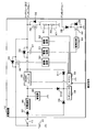
- FIG. 3 is a circuit diagram of the power feeding device 12.
- the power supply device 12 includes P-channel FETs (Field-Effect-Transistors) 40 and 41, N-channel FETs 42 and 43, a charging circuit 44, a capacitor 45, a DCDC converter 46, a detection circuit 47, a regulator 48, a microcomputer (hereinafter referred to as a microcomputer) 49), drive circuits 50, 51, 52, 53 and diodes D3, D4,..., D11.
- the detection circuit 47 has two resistors R1 and R2.
- Diodes D3, D4, D5, and D6 are parasitic diodes of FETs 40, 41, 42, and 43, respectively.
- the cathodes of the diodes D3 and D4 are connected to the sources of the FETs 40 and 41, respectively.
- the anodes of the diodes D3 and D4 are connected to the drains of the FETs 40 and 41, respectively.
- the cathodes of the diodes D5 and D6 are connected to the drains of the FETs 42 and 43, and the anodes of the diodes D5 and D6 are connected to the sources of the FETs 42 and 43.
- the positive electrode of the battery 10 is connected to the source of the FET 40.
- the drain of the FET 40 is connected to the drains of the FETs 41 and 42, and is connected to the NO terminal 20 c of the lock relay 13 and the NO terminal 30 c of the unlock relay 14.
- the detection circuit 47 is connected to the FET 42 in series. Specifically, the source of the FET 42 is connected to one end of the resistor R1, and the other end of the resistor R1 is connected to one end of the resistor R2. The other end of the resistor R2 is grounded. A connection node between the resistors R1 and R2 is connected to the microcomputer 49.
- the other end of the ignition switch 11 is connected to the anode of a diode D7.
- the cathode of the diode D7 is connected to the input terminal of the charging circuit 44.
- the output terminal of the charging circuit 44 is connected to one end of the battery 45.
- the other end of the battery 45 is grounded.
- the output terminal of the charging circuit 44 is further connected to a DCDC converter 46.
- the source of the FET 41 is further connected to the DCDC converter 46.
- the anode of the diode D8 is connected to the other end of the coil L2 of the unlock relay 14.
- the cathode of the diode D8 is connected to the drain of the FET 43.
- the source of the FET 43 is grounded.
- the anodes of the diodes D9, D10, and D11 are connected to the other end of the ignition switch 11, one end of the capacitor 45, and the source of the FET 41.
- the cathode of the diode D9 is connected to the cathodes of the diodes D10 and D11.
- a connection node between the cathodes of the diodes D9, D10, and D11 is connected to the input terminal of the regulator 48.
- the output terminal of the regulator 48 is connected to the microcomputer 49.
- the microcomputer 49 is further connected to the DCDC converter 46 and is connected to each of the four drive circuits 50, 51, 52 and 53.
- the microcomputer 49 is further grounded.
- the drive circuits 50, 51, 52, and 53 are further connected to the gates of the FETs 40, 41, 42, and 43, respectively.
- Each of the FETs 40, 41, 42, and 43 functions as a semiconductor switch. For each of the FETs 40 and 41, when the gate voltage relative to the source potential is less than a certain voltage, a current can flow between the drain and the source. At this time, each of the FETs 40 and 41 is on. For each of the FETs 40 and 41, when the gate voltage relative to the source potential is a certain voltage or higher, no current flows between the drain and the source. At this time, each of the FETs 40 and 41 is off. With respect to each of the FETs 40 and 41, the above-described constant voltage is a negative voltage.
- each of the FETs 42 and 43 when the gate voltage based on the source potential is a certain voltage or higher, a current can flow between the drain and the source. At this time, each of the FETs 42 and 43 is on. For each of the FETs 42 and 43, when the gate voltage relative to the source potential is less than a certain voltage, no current flows between the drain and the source. At this time, each of the FETs 42 and 43 is off. Regarding the FETs 42 and 43, the above-described constant voltage is a positive voltage.
- the gate voltages of the FETs 40, 41, 42, and 43 are adjusted by the drive circuits 50, 51, 52, and 53, respectively.
- Each of the drive circuits 50, 51, 52, 53 turns on or off the FETs 40, 41, 42, 43 in accordance with instructions from the microcomputer 49.
- the power supply apparatus 12 is provided with the first supply path for supplying the electric power input from the battery 10 to the motor 15 via the FET 40.
- the FET 40 functions as a first switch.
- One end of the detection circuit 47 that is, one end of the resistor R1 is connected to the first supply path via the FET.
- the FET 42 when the FET 42 is on, the FETs 40 and 41 are on and off, respectively.
- a current flows through the first supply path.
- the detection circuit 47 detects a voltage related to the voltage in the first supply path.
- the resistors R1 and R2 included in the detection circuit 47 divide the voltage in the first supply path. The voltage divided by the resistors R1 and R2 is input to the microcomputer 49.
- the voltage output from the detection circuit 47 to the microcomputer 49 is a detection voltage detected by the detection circuit 47.
- the voltage in the first supply path is referred to as a path voltage.
- the path voltage substantially matches the voltage output from the battery 10.
- the detection voltage is a predetermined number of path voltages, for example, a quarter of the path voltage. Of course, the higher the path voltage, the higher the detection voltage.
- the charging circuit 44 monitors the terminal voltage of the battery 45. When the terminal voltage of the battery 45 is less than a preset reference voltage, the charging circuit 44 supplies the power input from the battery 10 via the ignition switch 11 and the diode D7 to the battery 45 to charge the battery 45. To do. The charging circuit 44 stops power supply to the battery 45 when the terminal voltage of the battery 45 is equal to or higher than the reference voltage.
- the battery 45 is constituted by a plurality of capacitors (not shown) connected in series, for example. In this case, one end of a series circuit constituted by a plurality of capacitors is connected to the output end of the charging circuit 44, and the other end of the series circuit is grounded.
- the capacitor is, for example, an electric double layer capacitor.
- the battery 45 may be constituted by a battery such as a lithium ion battery or a nickel metal hydride battery instead of a capacitor.
- the DCDC converter 46 receives an operation instruction and a stop instruction from the microcomputer 49.
- the DCDC converter 46 operates in a state where the FET 41 is on.
- the DCDC converter 46 transforms the terminal voltage of the capacitor 45 to a predetermined target voltage that is set in advance, and the transformed voltage is changed to the NO of the lock relay 13 via the FET 41.
- the power feeding device 12 outputs the electric power stored in the battery 45 toward the NO terminals 20c and 30c.
- the target voltage is higher than zero volts and lower than the voltage output from the battery 10.
- the DCDC converter 46 stops operation when a stop instruction is input from the microcomputer 49.
- the regulator 48 receives the highest voltage among the voltage at the other end of the ignition switch 11, the terminal voltage of the capacitor 45, and the voltage at the source of the FET 41.
- the regulator 48 steps down the input voltage to a constant operating voltage to be output to the microcomputer 49 in order to operate the microcomputer 49, for example, 5 V, and outputs the operating voltage to the microcomputer 49. Thereby, electric power is supplied to the microcomputer 49.
- the microcomputer 49 is supplied with power from the capacitor 45 through the diode D10 and the regulator 48.
- the terminal voltage of the battery 10 is It is higher than both the terminal voltage and the output voltage of the DCDC converter 46.
- the target voltage output by the DCDC converter 46 is higher than the reference voltage used when the charging circuit 44 determines whether or not the battery 45 is charged. For this reason, the output voltage of the DCDC converter 46 is next to the terminal voltage of the battery 10. The terminal voltage of the capacitor 45 is the lowest.
- the microcomputer 49 operates when power is supplied via one of the diodes D9, D10, and D11, and stops operating when the supplied power is less than a certain level.
- the microcomputer 49 has a CPU (not shown) and a memory (not shown) in which a control program is stored. When the CPU executes the control program, the microcomputer 49 executes a power supply control process for controlling power supply to the motor 15.
- the microcomputer 49 instructs the drive circuits 50, 51, 52, and 53 to turn on or off the FETs 40, 41, 42, and 43, respectively.
- a collision signal is input to the microcomputer 49.
- the microcomputer 49 turns on or off the FETs 40, 41, 42, and 43 based on the content of the collision signal and the detection voltage input from the detection circuit 47.
- the microcomputer 49 functions as a control unit, a second control unit, and an input unit.
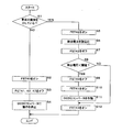
- FIG. 4 is a flowchart showing a procedure of power supply control processing executed by the microcomputer 49.
- the microcomputer 49 operates and periodically executes power supply control processing.
- the microcomputer 49 determines whether or not the input collision signal indicates a vehicle collision (step S1). If the microcomputer 49 determines that the collision signal does not indicate a vehicle collision (S1: NO), the microcomputer 49 instructs the drive circuit 50 to turn on the FET 40 (step S2), and instructs the drive circuits 51, 52, and 53. Then, the FETs 41, 42, 43 are turned off (step S3). Thereafter, the microcomputer 49 causes the DCDC converter 46 to stop operating by outputting a stop instruction to the DCDC converter 46 (step S4). The microcomputer 49 ends the power feeding control process after executing Step S4. The microcomputer 49 executes the power feeding control process again when the next cycle arrives.
- the FET 40 is on, the FETs 41, 42, and 43 are off, and the DCDC converter 46 stops operating.
- the control device 16 grounds one cathode of the diodes D1 and D2 and opens the other cathode, as described above, the electric power input from the battery 10 through the first supply path. Is supplied to the motor 15 as it is, and the motor 15 locks or unlocks the door.
- the microcomputer 49 When the engine stops and the ignition switch 11 is turned off without the collision signal indicating a vehicle collision, the microcomputer 49 is supplied with the electric power stored in the capacitor 45 via the diode D10 and the regulator 48. The microcomputer 49 continues the power supply control process. When the electric power stored in the battery 45 becomes less than a certain electric power, the microcomputer 49 stops its operation.
- the gate potential of each of the FETs 40, 41, 42, and 43 becomes the ground potential.
- the positive electrode of the battery 10 is connected to the source of the FET 40. Therefore, for each FET 40, when the gate potential is the ground potential, the gate voltage with respect to the source potential is maintained below a certain voltage. As a result, the FET 40 is kept on.
- the terminal voltage of the capacitor 45 is sufficiently low, and the source potential of the FET 41 substantially matches the ground potential. For this reason, the gate voltage of the FET 41 with respect to the source potential is substantially zero volts, and is maintained at a negative constant voltage or higher. Accordingly, the FET 41 is kept off at least after the microcomputer 49 stops operating until the ignition switch 11 is turned on.
- the microcomputer 49 determines that the input collision signal indicates a vehicle collision (S1: YES)
- the microcomputer 49 instructs the drive circuit 52 to turn on the FET 42 from off (step S5).
- the collision signal is switched from a state not indicating a vehicle collision to a state indicating a vehicle collision
- the microcomputer 49 executes step S5. Therefore, when the microcomputer 49 executes step S5, the FET 40 is on and the FETs 41 and 43 are off.
- the detection circuit 47 detects a voltage (detection voltage) related to the path voltage.
- the FET 42 functions as a third switch.
- the microcomputer 49 reads the detection voltage from the detection circuit 47 (step S6), and instructs the drive circuit 52 to turn off the FET 42 (step S7).
- the microcomputer 49 determines whether or not the detected voltage read in step S6 is less than a preset threshold value (step S8). Thereby, it is determined whether or not the battery 10 is lost.
- the threshold is above zero volts. Further, the threshold value is less than the voltage that is normally output from the battery 10 to the power supply device 12 and divided by the resistors R1 and R2 of the detection circuit 47. For example, the threshold value is set to the same value as the voltage obtained by dividing the target voltage output from the DCDC converter 46 by the resistors R1 and R2.
- step S8 when the battery 10 is lost, the detection voltage is approximately zero volts.
- the path voltage is substantially the same as the voltage output from the battery 10, and the detection voltage detected by the detection circuit 47 is equal to or higher than the threshold value.
- the microcomputer 49 also functions as a determination unit.
- the microcomputer 49 determines that the detected voltage is less than the threshold value (S8: YES), it instructs the drive circuit 50 to turn off the FET 40 (step S9), and instructs the drive circuit 51 to turn on the FET 41 (step S9). Step S10).
- the microcomputer 49 operates the DCDC converter 46 by outputting an operation instruction to the DCDC converter 46 (step S11). Thereby, the DCDC converter 46 transforms the terminal voltage of the battery 45 to the target voltage, and outputs the transformed voltage toward the NO terminal 20c of the lock relay 13 and the NO terminal 30c of the unlock relay 14 via the FET 41. To do.
- the microcomputer 49 turns on the FET 43 after executing Step S11 (Step S12). As described above, when the collision signal indicates a vehicle collision, the control device 16 opens the cathode of the diode D1. For this reason, no current flows through the coil L1, and the COM terminal 20a of the relay contact 20 is connected to the NC terminal 20b. When the microcomputer 49 executes steps S9 to S12, current flows from the DCDC converter 46 to the FET 41, the coil L2, the diode D8, and the FET 43 in this order, and the COM terminal 30a of the relay contact 30 is connected to the NO terminal 30c.
- the power feeding device 12 supplies the electric power stored in the battery 45 to the motor 15 via the FET 41.
- the current flows from the DCDC converter 46 to the FET 41, the NO terminal 30c, the COM terminal 30a, the motor 15, the COM terminal 20a, and the NC terminal 20b in this order, so the motor 15 unlocks the door.
- the power supply device 12 is provided with the second supply path for supplying the electric power stored in the battery 45 to the motor 15 via the DCDC converter 46 and the FET 41.
- a part of the first supply path and the second supply path are common.
- the drain of the FET 42 is connected to this common part.
- the FET 41 functions as a second switch.
- the common part is a part of the first supply path
- the FETs 40 and 41 are off and on
- the common part is a part of the second supply path.
- the detection circuit 47 does not detect a voltage related to the voltage in the second supply path.
- the microcomputer 49 determines that the detected voltage is equal to or higher than the threshold (S8: NO)
- the microcomputer 49 executes step S12.
- the microcomputer 49 keeps the FETs 40 and 41 on and off.
- the control device 16 opens the cathode of the diode D1. For this reason, no current flows through the coil L1, and the COM terminal 20a of the relay contact 20 is connected to the NC terminal 20b.
- step S12 When the microcomputer 49 executes step S12 with the FETs 40 and 41 turned on and off, the current flows from the battery 10 to the FET 40, the coil L2, the diode D8, and the FET 43 in this order, and the COM terminal 30a of the relay contact 30 is Connected to the NO terminal 30c.
- the power feeding device 12 supplies the electric power input from the battery 10 to the motor 15 via the FET 40.
- the NO terminal 30c, the COM terminal 30a, the motor 15, the COM terminal 20a, and the NC terminal 20b in this order the motor 15 unlocks the door.
- step S12 the microcomputer 49 ends the power supply control process and does not execute the power supply control process again.
- the battery 10 can stably supply a voltage higher than a certain voltage to the motor 15 as compared with the battery 45. For this reason, it is preferable that the battery 10 supplies power to the motor 15 rather than the battery 45.
- the microcomputer 49 complementarily turns the FETs 40 and 41 on and off based on the detection voltage detected by the detection circuit 47.
- the microcomputer 49 keeps the FETs 40 and 41 on and off when the detected voltage is equal to or higher than the threshold value, that is, when the battery 10 is not lost due to a vehicle collision. Thereby, electric power is supplied from the battery 10 to the motor 15 through the first supply path, and the motor 15 unlocks the door.
- the microcomputer 49 turns off and on the FETs 40 and 41 to operate the DCDC converter 46. Thereby, electric power is supplied from the battery 45 to the motor 15 via the second supply path, and the motor 15 unlocks the door.
- the complementary ON or OFF of the FETs 40 and 41 means that the FET 41 is OFF when the FET 40 is ON, and the FET 41 is ON when the FET 40 is OFF.
- the FET 42 is normally turned off.
- the microcomputer 49 turns the FET 42 on from off when the collision signal indicates a vehicle collision, and the detection circuit 47 consumes power. For this reason, the power consumed by the detection circuit 47 is low. Therefore, the power consumption of the power feeding device 12 including the detection circuit 47 is also low.
- the microcomputer 49 reads the detection voltage from the detection circuit 47 in a state where the FET 42 is on, and then turns the FET 42 off again from on, the power consumed by the detection circuit 47 is even lower. Therefore, the power consumption of the power feeding device 12 having the detection circuit 47 is further low.
- connection destination of the drain of the FET 42 is not limited to the drains of the FETs 40 and 41, but may be the first supply path. Therefore, the connection destination of the drain of the FET 42 may be the source of the FET 40. Since the FET 42 only needs to be connected in series to the detection circuit 47, one end of the resistor R1 is connected to the first supply path, the drain of the FET 42 is connected to the other end of the resistor R2, and the source of the FET 42 is grounded. May be.
- the power feeding device 12 may not include the FET 42. That is, one end of the resistor R1 may be connected to the first supply path, and the other end of the resistor R2 may be grounded. Even in this case, since the microcomputer 49 complementarily turns on or off the FETs 40 and 41 based on the detection voltage detected by the detection circuit 47, a voltage higher than a certain voltage is continuously motored with high probability. 15 can be output.
- the FET 41 is not limited to a P-channel type FET, and may be an N-channel type FET. In this case, the connection destination of the drain and the source in the FET 41 is opposite to the connection destination of the drain and the source in the case where the FET 41 is a P-channel FET. Further, when the FET 41 is an N-channel FET, the cathode and anode of the diode D4 are connected to the drain and source of the FET 41, respectively.
- Each of the FETs 42 and 43 is not limited to an N channel type FET, and may be a P channel type FET.
- the connection destination of the drain and the source in each of the FETs 42 and 43 is opposite to the connection destination of the drain and the source in the case where each of the FETs 42 and 43 is an N-channel FET.
- the FET 42 is a P-channel FET
- the cathode and anode of the diode D5 are connected to the source and drain of the FET 41, respectively.
- the FET 43 is a P-channel type FET
- the cathode and anode of the diode D6 are connected to the source and drain of the FET 43, respectively.
- FETs 40, 41, 42, and 43 may function as switches. For this reason, relay contacts may be used instead of the FETs 40, 41, 42 and 43.
Landscapes
- Engineering & Computer Science (AREA)
- Power Engineering (AREA)
- Business, Economics & Management (AREA)
- Emergency Management (AREA)
- Mechanical Engineering (AREA)
- Charge And Discharge Circuits For Batteries Or The Like (AREA)
Abstract
給電装置(12)には、バッテリ(10)から入力された電力をモータに供給する第1供給経路と、蓄電器(45)が蓄えた電力をモータに供給する第2供給経路とが設けられている。第1供給経路及び第2供給経路夫々にはFET(40,41)が設けられている。FET(42)を介して、第1供給経路に検出回路(47)の一端が接続されており、検出回路(47)は第1供給経路における電圧に係る電圧を検出する。マイコン(49)は、駆動回路(50,51)夫々に指示してFET(40,41)をオン又はオフにする。マイコン(49)は、検出回路(47)が検出した検出電圧に基づいて、FET(40,41)を相補的にオン又はオフにする。
Description
本発明は蓄電器に蓄えられた電力を供給する給電装置に関する。
負荷に電力を供給する給電装置として、蓄電器を備え、蓄電器に蓄えられた電力を負荷に供給する給電装置が提案されている(例えば、特許文献1参照)。
図1は従来の給電装置80の回路図である。給電装置80、バッテリ81及び負荷82は車両に搭載されている。給電装置80は、バッテリ81の正極及び負荷82の一端に各別に接続されており、バッテリ81の負極及び負荷82の他端は接地されている。給電装置80は、バッテリ81に蓄えられている電力、又は、内部に蓄えられている電力を負荷82に供給する。
給電装置80は、スイッチ90,91、蓄電器92及びDCDCコンバータ93を備える。スイッチ90の一端はバッテリ81の正極に接続されており、スイッチ90の他端は負荷82の一端に接続されている。蓄電器92の一端はDCDCコンバータ93に接続されており、蓄電器92の他端は接地されている。DCDCコンバータ93は、更に、スイッチ91の一端に接続されており、スイッチ91の他端は負荷82の一端に接続されている。
給電装置80では、通常、スイッチ90,91夫々はオン及びオフであり、DCDCコンバータ93は動作を停止している。このため、バッテリ81から電力がスイッチ90を介して負荷82に供給される。
車両が衝突した場合、スイッチ90,91夫々はオフ及びオンにされ、DCDCコンバータ93が作動する。この場合、DCDCコンバータ93は、蓄電器92の端子電圧を変圧し、変圧した電圧を、スイッチ91を介して負荷82に出力する。これにより、蓄電器92から負荷82に電力が供給される。
以上のように構成された従来の給電装置80では、車両が衝突してバッテリ81が喪失された場合であっても、蓄電器92に蓄えられた電力を負荷82に供給することができる。
蓄電器92に蓄えられた電力は、バッテリ81が喪失された場合において、負荷82に特定の動作を行わせるために消費される。そのため、蓄電器92は大量の電力を蓄える必要はない。このため、蓄電器92として、例えば、直列に接続された複数のコンデンサが用いられる。
しかしながら、コンデンサの内部抵抗は、コンデンサの周辺温度によって異なり、該周辺温度が低い程大きい。大きさが同じ電流が蓄電器から流れた場合において、内部抵抗が大きい程、蓄電器92から出力される電圧は低い。
また、温度が高い場所にコンデンサが配置され続けた場合、コンデンサの静電容量が低下する。蓄電器92として直列に接続された複数のコンデンサが用いられた場合、蓄電器92の端子電圧が所定電圧に維持されるように、蓄電器92は充電される。静電容量が小さい場合においては、蓄電器92の端子電圧が所定電圧であるときに蓄電器92に蓄えられている電力は少ない。このため、静電容量が小さい場合、蓄電器92から一定電圧以上の電圧を出力することが可能な期間が短い。
蓄電器92がリチウムイオン電池又はニッケル水素電池等の電池を用いて構成される場合においても、電池の内部抵抗は、電池の周辺温度が低い程大きい。更に、温度が高い場所にリチウムイオン電池又はニッケル水素電池等の電池が配置され続けた場合、電池の容量が低下する。容量が小さい場合、蓄電器92から一定電圧以上の電圧を出力することが可能な期間は短い。
蓄電器92がリチウムイオン電池又はニッケル水素電池等の電池を用いて構成される場合においても、電池の内部抵抗は、電池の周辺温度が低い程大きい。更に、温度が高い場所にリチウムイオン電池又はニッケル水素電池等の電池が配置され続けた場合、電池の容量が低下する。容量が小さい場合、蓄電器92から一定電圧以上の電圧を出力することが可能な期間は短い。
従って、従来の給電装置80では、車両が衝突した場合、必ず蓄電器92から負荷82に電力が供給されるため、車両が衝突した時点における内部抵抗と蓄電器92の周辺温度とによっては、一定電圧以上の電圧を持続的に出力することができない虞がある。
本発明は斯かる事情に鑑みてなされたものであり、その目的とするところは、一定電圧以上の電圧を高い確率で持続的に出力することが可能な給電装置を提供することにある。
本発明に係る給電装置は、外部から入力された電力を供給する第1供給経路と、蓄電器が蓄えた電力を供給する第2供給経路とを備える給電装置において、前記第1供給経路に設けられた第1スイッチと、前記第2供給経路に設けられた第2スイッチと、前記第1供給経路に一端が接続され、該第1供給経路における電圧に係る電圧を検出する検出回路と、該検出回路が検出した検出電圧に基づいて、前記第1スイッチ及び第2スイッチを相補的にオン又はオフにする制御部とを備えることを特徴とする。
本発明にあっては、外部から入力された電力を負荷に供給する第1供給経路と、蓄電器が蓄えた電力を負荷に供給する第2供給経路とが設けられている。第1供給経路及び第2供給経路夫々には第1スイッチ及び第2スイッチが設けられている。また、第1供給経路には検出回路の一端が接続されており、検出回路は第1供給経路における電圧に係る電圧を検出する。検出回路が検出した検出電圧に基づいて第1スイッチ及び第2スイッチを相補的にオン又はオフにする。
例えば、第1スイッチ及び第2スイッチ夫々がオン及びオフであって、第1供給経路を介して負荷に電力が供給されている状態で、第1供給経路における電圧に係る電圧が所定電圧未満である場合、第1スイッチ及び第2スイッチ夫々をオフ及びオンにし、蓄電器92が蓄えた電力を負荷に供給する。
これにより、一定電圧以上の電圧を高い確率で持続的に出力することが可能である。
これにより、一定電圧以上の電圧を高い確率で持続的に出力することが可能である。
本発明に係る給電装置は、前記第1スイッチ及び第2スイッチ夫々がオン及びオフである状態で、前記検出電圧が閾値以上であるか否かを判定する判定部を備え、前記制御部は、該判定部によって、前記検出電圧が前記閾値未満であると判定された場合に前記第1スイッチ及び第2スイッチ夫々をオフ及びオンにし、前記判定部によって、前記検出電圧が前記閾値以上であると判定された場合に前記第1スイッチ及び第2スイッチ夫々をオン及びオフに維持することを特徴とする。
本発明にあっては、第1スイッチ及び第2スイッチ夫々がオン及びオフであって、第1供給経路を介して、外部から負荷に電力が供給されている場合において、検出回路が検出した検出電圧が閾値未満となったとき、第1スイッチ及び第2スイッチ夫々をオフ及びオンにする。これにより、第2供給経路を介して、蓄電器92から負荷に電力が供給される。
同様の場合において検出電圧が閾値以上であるとき、第1スイッチ及び第2スイッチ夫々をオン及びオフに維持する。これにより、第1供給経路を介して、外部から負荷に電力が供給される。
本発明に係る給電装置は、前記検出回路に直列に接続された第3スイッチと、車両が衝突したか否かを示す衝突信号が入力される入力部と、該入力部に入力された前記衝突信号が前記車両の衝突を示す場合に前記第3スイッチをオフからオンにする第2の制御部とを備え、前記判定部は、前記入力部に入力された前記衝突信号が前記車両の衝突を示す場合に判定を行うことを特徴とする。
本発明にあっては、検出回路に直列に接続された第3スイッチがオフである場合、検出回路は、第1供給経路における電圧に係る電圧を検出することはなく、電力を消費することはない。入力部に入力された衝突信号が車両の衝突を示す場合、第3スイッチをオフからオンにする。これにより、検出回路は、第1供給経路における電圧に係る電圧を検出し、電力を消費する。第3スイッチがオフからオンにすると共に、検出電圧が閾値以上であるか否かを判定する。衝突信号が車両の衝突を示す場合に検出回路は電力を消費するので、消費電力は低い。
本発明に係る給電装置は、前記判定部は前記検出回路から前記検出電圧を読込み、前記第2の制御部は、前記判定部が前記検出電圧を読込んだ後、前記第3スイッチをオンからオフにすることを特徴とする。
本発明にあっては、第3スイッチがオンからオフにした後、検出電圧が閾値以上であるか否かを判定するため、検出回路から検出電圧を読込む。その後、第3スイッチをオンからオフにする。このため、検出回路が消費する電力は更に低い。
本発明によれば、一定電圧以上の電圧を高い確率で持続的に出力することが可能な給電装置を実現することができる。
以下、本発明をその実施の形態を示す図面に基づいて詳述する。
図2は本実施の形態における電源システム1の要部構成を示すブロック図である。電源システム1は、車両に好適に搭載され、バッテリ10、イグニッションスイッチ11、給電装置12、ロックリレー13、アンロックリレー14、モータ15、制御装置16及びダイオードD1,D2を備える。
図2は本実施の形態における電源システム1の要部構成を示すブロック図である。電源システム1は、車両に好適に搭載され、バッテリ10、イグニッションスイッチ11、給電装置12、ロックリレー13、アンロックリレー14、モータ15、制御装置16及びダイオードD1,D2を備える。
ロックリレー13はリレー接点20及びコイルL1を有する。リレー接点20は、切替えスイッチであり、COM(Common)端子20a、NC(Normally Close)端子20b及びNO(Normally Open)端子20cを有する。
同様に、アンロックリレー14はリレー接点30及びコイルL2を有する。リレー接点30も、切替えスイッチであり、COM端子30a、NC端子30b及びNO端子30cを有する。
同様に、アンロックリレー14はリレー接点30及びコイルL2を有する。リレー接点30も、切替えスイッチであり、COM端子30a、NC端子30b及びNO端子30cを有する。
バッテリ10の正極はイグニッションスイッチ11の一端に接続されている。バッテリ10の正極、及び、イグニッションスイッチ11の他端は給電装置12に各別に接続されている。バッテリ10の負極は接地されている。ロックリレー13のリレー接点20におけるNO端子20cは、アンロックリレー14のリレー接点30におけるNO端子30cに接続されている。給電装置12は、更に、NO端子20c,30c間の接続ノードに接続されている。リレー接点20のNC端子20bと、リレー接点30のNC端子30bとは接地されている。リレー接点20のCOM端子20aと、リレー接点30のCOM端子30aとはモータ15に各別に接続されている。
NO端子20c,30c間の接続ノードには、ロックリレー13のコイルL1の一端と、アンロックリレー14のコイルL2の一端とが接続されている。コイルL1の他端はダイオードD1のアノードに接続されている。コイルL2の他端は、給電装置12と、ダイオードD2のアノードとに接続されている。ダイオードD1,D2夫々のカソードは制御装置16に接続されている。制御装置16は接地もされている。
バッテリ10は、例えば、鉛蓄電池であり、車両の図示しないエンジンと連動して発電する図示しない発電機から供給された直流の電力を蓄える。バッテリ10は、イグニッションスイッチ11が設けられていない供給経路を介して、電力を給電装置12に出力する。バッテリ10は、更に、イグニッションスイッチ11がオンである場合、イグニッションスイッチ11を介して電力を給電装置12に出力する。
イグニッションスイッチ11は、エンジンが作動している場合にオンであり、エンジンが動作を停止している場合にオフである。
イグニッションスイッチ11は、エンジンが作動している場合にオンであり、エンジンが動作を停止している場合にオフである。
給電装置12は、イグニッションスイッチ11がオンである場合、イグニッションスイッチ11を介して、バッテリ10から出力された電力を蓄える。給電装置12には、車両が衝突したか否かを示す衝突信号が入力される。
衝突信号は、例えば、エアバッグを制御するECU(Electronic Control Unit)から出力される。車両が衝突したか否かは、例えば、車両の加速度を検出する加速度センサの検出結果に基づいて判定される。
給電装置12は、更に、バッテリ10が喪失されたか否かを判定する。
衝突信号は、例えば、エアバッグを制御するECU(Electronic Control Unit)から出力される。車両が衝突したか否かは、例えば、車両の加速度を検出する加速度センサの検出結果に基づいて判定される。
給電装置12は、更に、バッテリ10が喪失されたか否かを判定する。
給電装置12は、入力された衝突信号が車両の衝突を示していない場合、NO端子20c,30cに向けて、バッテリ10から入力された電力をそのまま出力し、アンロックリレー14におけるコイルL2の他端に接続されている給電装置12の一端を開放する。
給電装置12は、入力された衝突信号が車両の衝突を示す場合において、バッテリ10が喪失されていないと判定したとき、NO端子20c,30cに向けて、バッテリ10から入力された電力をそのまま出力し、アンロックリレー14におけるコイルL2の他端から電流を引込む。
給電装置12は、入力された衝突信号が車両の衝突を示す場合において、バッテリ10が喪失されていると判定したとき、NO端子20c,30cに向けて、蓄えた電力を出力し、アンロックリレー14におけるコイルL2の他端から電流を引込む。
給電装置12は、入力された衝突信号が車両の衝突を示す場合において、バッテリ10が喪失されていると判定したとき、NO端子20c,30cに向けて、蓄えた電力を出力し、アンロックリレー14におけるコイルL2の他端から電流を引込む。
ロックリレー13において、コイルL1に電流が流れていない場合、リレー接点20のCOM端子20aに接続されている導体は、NC端子20bに接触しており、COM端子20aはNC端子20bに接続されている。コイルL1に電流が流れた場合、コイルL1周辺に磁界が発生し、コイルL1はCOM端子20aに接続されている導体を引付け、該導体はNO端子20cに接触する。これにより、リレー接点20のCOM端子20aはNO端子20cに接続される。コイルL1への電流供給が停止した場合、磁界の発生が停止し、COM端子20aに接続されている導体はNC端子20bに接触する。これにより、COM端子20aは再びNC端子20bに接続する。
アンロックリレー14はロックリレー13と同様に作用する。ロックリレー13の作用の説明において、コイルL1、リレー接点20、COM端子20a、NC端子20b及びNO端子20c夫々を、コイルL2、リレー接点30、COM端子30a、NC端子30b及びNO端子30cに置き換えることによって、アンロックリレー14を説明することができる。
モータ15は、車両のドアをロック又はアンロックする直流モータであり、車両に搭載された負荷である。モータ15において、ロックリレー13側からアンロックリレー14側に電流が流れた場合、モータ15はドアをロックする。モータ15において、アンロックリレー14側からロックリレー13側に電流が流れた場合、モータ15はドアをアンロックする。
制御装置16にも衝突信号が入力される。制御装置16は、入力された衝突信号が車両の衝突を示していない場合、モータ15にドアのロック及びアンロックを行わせる。
衝突信号が車両の衝突を示していない場合、前述したように、給電装置12は、NO端子20c,30cに向けてバッテリ10の電力を出力している。
制御装置16は、衝突信号が車両の衝突を示していない場合において、ドアをロックするとき、ダイオードD1のカソードを接地させ、ダイオードD2のカソードを開放させる。これにより、電流が、給電装置12から、コイルL1、ダイオードD1及び制御装置16の順に流れ、リレー接点20のCOM端子20aはNO端子20cに接続される。コイルL2には電流が流れないため、リレー接点30のCOM端子30aはNC端子30bに接続されている。この場合、電流が、給電装置12から、NO端子20c、COM端子20a、モータ15、COM端子30a及びNC端子30bの順に流れ、モータ15はドアをロックする。
制御装置16は、衝突信号が車両の衝突を示していない場合において、ドアをロックするとき、ダイオードD1のカソードを接地させ、ダイオードD2のカソードを開放させる。これにより、電流が、給電装置12から、コイルL1、ダイオードD1及び制御装置16の順に流れ、リレー接点20のCOM端子20aはNO端子20cに接続される。コイルL2には電流が流れないため、リレー接点30のCOM端子30aはNC端子30bに接続されている。この場合、電流が、給電装置12から、NO端子20c、COM端子20a、モータ15、COM端子30a及びNC端子30bの順に流れ、モータ15はドアをロックする。
制御装置16は、衝突信号が車両の衝突を示していない場合において、ドアをアンロックするとき、ダイオードD1のカソードを開放させ、ダイオードD2のカソードを接地させる。これにより、電流が、給電装置12から、コイルL2、ダイオードD2及び制御装置16の順に流れ、リレー接点30のCOM端子30aはNO端子30cに接続される。コイルL1には電流が流れないため、リレー接点20のCOM端子20aはNC端子20bに接続されている。この場合、電流が、給電装置12から、NO端子30c、COM端子30a、モータ15、COM端子20a及びNC端子20bの順に流れ、モータ15はドアをアンロックする。
制御装置16は、衝突信号が車両の衝突を示していない場合において、ドアのロック及びアンロックのいずれも行わないとき、ダイオードD1,D2夫々のカソードを開放させる。この場合、リレー接点20のCOM端子20aはNC端子20bに接続され、リレー接点30のCOM端子30aはNC端子30bに接続されているため、モータ15の両端は接地されており、モータ15は動作を停止する。
制御装置16は、衝突信号が車両の衝突を示した場合、ダイオードD1のカソードを開放させる。衝突信号が車両の衝突を示した場合、前述したように、給電装置12は、バッテリ10から入力された電力、又は、蓄えた電力をNO端子20c,30cに向けて出力し、コイルL2から電流を自装置に引込む。これにより、電流が、給電装置12からコイルL2に流れて給電装置12に戻り、リレー接点30のCOM端子30aはNO端子30cに接続される。コイルL1には電流が流れないため、リレー接点20のCOM端子20aはNC端子20bに接続されている。この場合、電流が、給電装置12から、NO端子30c、COM端子30a、モータ15、COM端子20a及びNC端子20bの順に流れ、モータ15はドアをアンロックする。
図3は給電装置12の回路図である。給電装置12は、Pチャネル型のFET(Field Effect Transistor)40,41、Nチャネル型のFET42,43、充電回路44、蓄電器45、DCDCコンバータ46、検出回路47、レギュレータ48、マイクロコンピュータ(以下ではマイコンという)49、駆動回路50,51,52,53及びダイオードD3,D4,・・・,D11を有する。検出回路47は2つの抵抗R1,R2を有する。
ダイオードD3,D4,D5,D6夫々は、FET40,41,42,43の寄生ダイオードである。ダイオードD3,D4夫々のカソードは、FET40,41のソースに接続されている。ダイオードD3,D4夫々のアノードは、FET40,41のドレインに接続されている。ダイオードD5,D6夫々のカソードはFET42,43のドレインに接続され、ダイオードD5,D6夫々のアノードはFET42,43のソースに接続されている。
バッテリ10の正極はFET40のソースに接続されている。FET40のドレインは、FET41,42夫々のドレインに接続されると共に、ロックリレー13のNO端子20c及びアンロックリレー14のNO端子30cに接続されている。検出回路47はFET42に直列に接続されている。具体的には、FET42のソースは抵抗R1の一端に接続されており、抵抗R1の他端は抵抗R2の一端に接続されている。抵抗R2の他端は接地されている。抵抗R1,R2間の接続ノードはマイコン49に接続されている。
イグニッションスイッチ11の他端にはダイオードD7のアノードが接続されている。ダイオードD7のカソードは充電回路44の入力端に接続されている。充電回路44の出力端は、蓄電器45の一端に接続されている。蓄電器45の他端は接地されている。
充電回路44の出力端は、更に、DCDCコンバータ46に接続されている。DCDCコンバータ46には、更に、FET41のソースが接続されている。
ダイオードD8のアノードは、アンロックリレー14のコイルL2の他端に接続されている。ダイオードD8のカソードはFET43のドレインに接続されている。FET43のソースは接地されている。
ダイオードD9,D10,D11夫々のアノードは、イグニッションスイッチ11の他端、蓄電器45の一端、及び、FET41のソースに接続されている。ダイオードD9のカソードは、ダイオードD10,D11夫々のカソードに接続されている。ダイオードD9,D10,D11夫々のカソード間の接続ノードはレギュレータ48の入力端に接続されている。レギュレータ48の出力端はマイコン49に接続されている。マイコン49は、更に、DCDCコンバータ46に接続されると共に、4つの駆動回路50,51,52,53に各別に接続されている。マイコン49は更に接地されている。駆動回路50,51,52,53夫々は、更に、FET40,41,42,43のゲートに接続されている。
FET40,41,42,43夫々は半導体スイッチとして機能する。
FET40,41夫々について、ソースの電位を基準としたゲートの電圧が一定電圧未満である場合、ドレイン及びソース間に電流が流れることが可能となる。このとき、FET40,41夫々はオンである。FET40,41夫々について、ソースの電位を基準としたゲートの電圧が一定電圧以上である場合、ドレイン及びソース間に電流が流れることはない。このとき、FET40,41夫々はオフである。FET40,41夫々に関して、前述した一定電圧は負の電圧である。
FET40,41夫々について、ソースの電位を基準としたゲートの電圧が一定電圧未満である場合、ドレイン及びソース間に電流が流れることが可能となる。このとき、FET40,41夫々はオンである。FET40,41夫々について、ソースの電位を基準としたゲートの電圧が一定電圧以上である場合、ドレイン及びソース間に電流が流れることはない。このとき、FET40,41夫々はオフである。FET40,41夫々に関して、前述した一定電圧は負の電圧である。
FET42,43夫々について、ソースの電位を基準としたゲートの電圧が一定電圧以上である場合、ドレイン及びソース間に電流が流れることが可能となる。このとき、FET42,43夫々はオンである。FET42,43夫々について、ソースの電位を基準としたゲートの電圧が一定電圧未満である場合、ドレイン及びソース間に電流が流れることはない。このとき、FET42,43夫々はオフである。FET42,43夫々に関して、前述した一定電圧は正の電圧である。
FET40,41,42,43夫々のゲートの電圧は駆動回路50,51,52,53によって調整される。駆動回路50,51,52,53夫々は、マイコン49の指示に従って、FET40,41,42,43をオン又はオフにする。
FET40,41夫々がオン及びオフである場合において、制御装置16がダイオードD1,D2中の一方のカソードを接地させ、他方のカソードを開放させたとき、バッテリ10から入力された電力は、FET40を介して、モータ15に供給される。このように、給電装置12には、バッテリ10から入力された電力を、FET40を介して、モータ15に供給する第1供給経路が設けられている。FET40は第1スイッチとして機能する。
検出回路47の一端、即ち、抵抗R1の一端は、FET42を介して第1供給経路に接続されている。後述するように、FET42がオンである場合、FET40,41夫々はオン及びオフである。FET40,41夫々がオン及びオフである場合、第1供給経路に電流が流れる。FET40,41,42夫々がオン、オフ及びオンである場合、第1供給経路から検出回路47に電流が流れ、検出回路47は、第1供給経路における電圧に係る電圧を検出する。具体的には、検出回路47が有する抵抗R1,R2が第1供給経路における電圧を分圧する。抵抗R1,R2が分圧した電圧はマイコン49に入力される。
検出回路47からマイコン49に出力される電圧は、検出回路47が検出した検出電圧である。また、以下では、第1供給経路における電圧を経路電圧と記載する。バッテリ10が喪失されることなく正常に接続されており、かつ、FET40,41夫々がオン及びオフである場合、経路電圧はバッテリ10から出力された電圧に略一致する。
検出電圧は、経路電圧の所定数分の1、例えば、経路電圧の4分の1である。当然のことながら、経路電圧が高い程、検出電圧も高い。第1供給経路からFET42を介して検出回路47に電流が流れた場合、検出回路47の抵抗R1,R2夫々では電力が消費される。
充電回路44は蓄電器45の端子電圧を監視している。充電回路44は、蓄電器45の端子電圧が予め設定されている基準電圧未満である場合、バッテリ10からイグニッションスイッチ11及びダイオードD7を介して入力された電力を蓄電器45に供給し、蓄電器45を充電する。充電回路44は、蓄電器45の端子電圧が基準電圧以上である場合、蓄電器45への電力供給を停止する。
蓄電器45は、例えば、直列に接続された複数の図示しないコンデンサによって構成される。この場合、複数のコンデンサによって構成される直列回路の一端は充電回路44の出力端に接続され、該直列回路の他端は接地される。コンデンサは例えば電気二重層キャパシタである。また、蓄電器45は、コンデンサではなく、リチウムイオン電池又はニッケル水素電池等の電池によって構成されてもよい。
蓄電器45は、例えば、直列に接続された複数の図示しないコンデンサによって構成される。この場合、複数のコンデンサによって構成される直列回路の一端は充電回路44の出力端に接続され、該直列回路の他端は接地される。コンデンサは例えば電気二重層キャパシタである。また、蓄電器45は、コンデンサではなく、リチウムイオン電池又はニッケル水素電池等の電池によって構成されてもよい。
DCDCコンバータ46には、マイコン49から作動指示及び停止指示が入力される。DCDCコンバータ46は、FET41がオンである状態で作動する。DCDCコンバータ46は、マイコン49から作動指示が入力された場合、蓄電器45の端子電圧を、予め設定されている一定の目標電圧に変圧し、変圧した電圧を、FET41を介してロックリレー13のNO端子20c及びアンロックリレー14のNO端子30cに向けて出力する。このように、給電装置12は、蓄電器45に蓄えられている電力をNO端子20c,30cに向けて出力する。目標電圧は、ゼロボルトよりも高く、バッテリ10から出力される電圧よりも低い。
DCDCコンバータ46は、マイコン49から停止指示が入力された場合、動作を停止する。
DCDCコンバータ46は、マイコン49から停止指示が入力された場合、動作を停止する。
レギュレータ48には、イグニッションスイッチ11の他端における電圧、蓄電器45の端子電圧、及び、FET41のソースにおける電圧の中で最も高い電圧が入力される。レギュレータ48は、入力された電圧を、マイコン49を作動させるためにマイコン49に出力すべき一定の作動電圧、例えば5Vに降圧し、該作動電圧をマイコン49に出力する。これにより、マイコン49に電力が供給される。
イグニッションスイッチ11の他端における電圧が、蓄電器45の端子電圧、及び、FET41のソースにおける電圧のいずれよりも高い場合、マイコン49には、バッテリ10からダイオードD9及びレギュレータ48を介して電力が供給される。
FET41のソースにおける電圧が、イグニッションスイッチ11の他端における電圧、及び、蓄電器45の端子電圧のいずれよりも高い場合、マイコン49には、DCDCコンバータ46からダイオードD11及びレギュレータ48を介して電力が供給される。
FET41のソースにおける電圧が、イグニッションスイッチ11の他端における電圧、及び、蓄電器45の端子電圧のいずれよりも高い場合、マイコン49には、DCDCコンバータ46からダイオードD11及びレギュレータ48を介して電力が供給される。
蓄電器45の端子電圧が、イグニッションスイッチ11の他端における電圧、及び、FET41のソースにおける電圧のいずれよりも高い場合、マイコン49には、蓄電器45からダイオードD10及びレギュレータ48を介して電力が供給される。
バッテリ10の正極がイグニッションスイッチ11の一端に正常に接続されている場合において、イグニッションスイッチ11及びFET41がオンであってDCDCコンバータ46が作動しているとき、バッテリ10の端子電圧は、蓄電器45の端子電圧、及び、DCDCコンバータ46の出力電圧のいずれよりも高い。DCDCコンバータ46が出力する目標電圧は、充電回路44が蓄電器45の充電を行うか否かを判定する場合に用いられる基準電圧よりも高い。このため、バッテリ10の端子電圧の次に、DCDCコンバータ46の出力電圧が高い。蓄電器45の端子電圧が最も低い。
マイコン49は、ダイオードD9,D10,D11の1つを介して電力が供給されている場合に作動し、供給されている電力が一定電力未満となった場合に動作を停止する。マイコン49は、図示しないCPUと、制御プログラムが記憶されている図示しないメモリとを有する。CPUが制御プログラムを実行することによって、マイコン49はモータ15への給電を制御する給電制御処理を実行する。
給電制御処理では、マイコン49は、駆動回路50,51,52,53夫々に指示して、FET40,41,42,43をオン又はオフにする。マイコン49には衝突信号が入力される。マイコン49は、衝突信号の内容と、検出回路47から入力された検出電圧とに基づいて、FET40,41,42,43夫々をオン又はオフにする。マイコン49は制御部、第2の制御部及び入力部として機能する。
図4はマイコン49が実行する給電制御処理の手順を示すフローチャートである。エンジンが作動してイグニッションスイッチ11がオンとなった場合、バッテリ10からイグニッションスイッチ11及びダイオードD9を介して、マイコン49に電力が供給される。この電力供給によって、マイコン49は作動し、給電制御処理を周期的に実行する。
給電制御処理では、まず、マイコン49は、入力されている衝突信号が車両の衝突を示しているか否かを判定する(ステップS1)。マイコン49は、衝突信号が車両の衝突を示していないと判定した場合(S1:NO)、駆動回路50に指示して、FET40をオンにし(ステップS2)、駆動回路51,52,53に指示して、FET41,42,43をオフする(ステップS3)。その後、マイコン49は、DCDCコンバータ46に停止指示を出力することによって、DCDCコンバータ46に動作を停止させる(ステップS4)。マイコン49は、ステップS4を実行した後、給電制御処理を終了する。マイコン49は、次の周期が到来した場合、再び給電制御処理を実行する。
以上のように、衝突信号が車両の衝突を示していない間、FET40がオンであり、FET41,42,43がオフであり、DCDCコンバータ46は動作を停止している。この状態で、制御装置16がダイオードD1,D2中の一方のカソードを接地させ、他方のカソードを開放させた場合、前述したように、第1供給経路を介して、バッテリ10から入力された電力がそのままモータ15に供給され、モータ15がドアのロック又はアンロックを行う。
衝突信号が車両の衝突を示すことなく、エンジンが停止してイグニッションスイッチ11がオフとなった場合、マイコン49には蓄電器45に蓄えられている電力がダイオードD10及びレギュレータ48を介して供給され、マイコン49は給電制御処理を継続する。蓄電器45が蓄えている電力が一定電力未満となった場合、マイコン49は動作を停止する。
マイコン49が動作を停止した場合、FET40,41,42,43夫々のゲートの電位は接地電位となる。FET40のソースにバッテリ10の正極が接続されている。このため、FET40夫々について、ゲートの電位が接地電位である場合、ソースの電位を基準としたゲートの電圧が一定電圧未満に維持される。結果、FET40はオンに維持される。
マイコン49が動作を停止した時点では、蓄電器45の端子電圧は十分に低く、FET41におけるソースの電位は接地電位に略一致する。このため、FET41について、ソースの電位を基準としたゲートの電圧は、略ゼロボルトであり、負の一定電圧以上に維持される。従って、少なくとも、マイコン49が動作を停止してからイグニッションスイッチ11がオンになるまでの間、FET41はオフに維持される。
FET42,43夫々について、ゲートの電位が接地電位である場合、ソースの電位を基準としたゲートの電圧は略ゼロボルトであり、正の一定電圧未満である。このため、マイコン49が動作を停止している場合、FET42,43夫々はオフである。
マイコン49は、入力されている衝突信号が車両の衝突を示していると判定した場合(S1:YES)、駆動回路52に指示してFET42をオフからオンにする(ステップS5)。衝突信号が車両の衝突を示していない状態から車両の衝突を示す状態に切替わった場合にマイコン49はステップS5を実行する。従って、マイコン49がステップS5を実行した時点においては、FET40はオンであり、FET41,43はオフである。FET42がオンである場合、検出回路47は経路電圧に係る電圧(検出電圧)を検出する。FET42は第3スイッチとして機能する。
次に、マイコン49は、検出回路47から検出電圧を読込み(ステップS6)、駆動回路52に指示してFET42をオンからオフにする(ステップS7)。次に、マイコン49は、ステップS6で読込んだ検出電圧が予め設定されている閾値未満であるか否かを判定する(ステップS8)。これにより、バッテリ10が喪失されているか否かを判定する。閾値は、ゼロボルトを超えている。更に、閾値は、バッテリ10が給電装置12に通常出力する電圧を、検出回路47の抵抗R1,R2が分圧した電圧未満である。閾値は、例えば、DCDCコンバータ46から出力される目標電圧を抵抗R1,R2が分圧した電圧と同じ値に設定される。
ステップS8について、バッテリ10が喪失されている場合、検出電圧は略ゼロボルトである。バッテリ10が喪失されていない場合、経路電圧は、バッテリ10から出力される電圧と略同じであり、検出回路47が検出した検出電圧は閾値以上である。マイコン49は判定部としても機能する。
マイコン49は、検出電圧が閾値未満であると判定した場合(S8:YES)、駆動回路50に指示してFET40をオフにし(ステップS9)、駆動回路51に指示してFET41をオンにする(ステップS10)。次に、マイコン49は、DCDCコンバータ46に作動指示を出力することによって、DCDCコンバータ46を作動させる(ステップS11)。これにより、DCDCコンバータ46は、蓄電器45の端子電圧を目標電圧に変圧し、変圧した電圧を、FET41を介して、ロックリレー13のNO端子20c及びアンロックリレー14のNO端子30cに向けて出力する。
マイコン49は、ステップS11を実行した後、FET43をオンにする(ステップS12)。前述したように、衝突信号が車両の衝突を示した場合、制御装置16はダイオードD1のカソードを開放させる。このため、コイルL1に電流は流れておらず、リレー接点20のCOM端子20aはNC端子20bに接続されている。また、マイコン49がステップS9~S12を実行した場合、電流がDCDCコンバータ46からFET41、コイルL2、ダイオードD8、FET43の順に流れ、リレー接点30のCOM端子30aはNO端子30cに接続される。
これにより、給電装置12は、蓄電器45に蓄えられた電力を、FET41を介してモータ15に供給する。このとき、電流がDCDCコンバータ46からFET41、NO端子30c、COM端子30a、モータ15、COM端子20a及びNC端子20bの順に流れるので、モータ15はドアをアンロックする。
以上のように、給電装置12には、蓄電器45が蓄えた電力を、DCDCコンバータ46及びFET41を介して、モータ15に供給する第2供給経路が設けられている。第1供給経路及び第2供給経路の一部は共通している。この共通部分にFET42のドレインが接続されている。FET41は第2スイッチとして機能する。
なお、FET40,41がオン及びオフである場合、共通部分は第1供給経路の一部であり、FET40,41がオフ及びオンである場合、共通部分は第2供給経路の一部である。また、FET40,41がオフ及びオンである場合、言い換えると、第2供給経路に電流が流れている場合、FET42はオフであり、オンとなることない。このため、検出回路47は、第2供給経路における電圧に係る電圧を検出することはない。
なお、FET40,41がオン及びオフである場合、共通部分は第1供給経路の一部であり、FET40,41がオフ及びオンである場合、共通部分は第2供給経路の一部である。また、FET40,41がオフ及びオンである場合、言い換えると、第2供給経路に電流が流れている場合、FET42はオフであり、オンとなることない。このため、検出回路47は、第2供給経路における電圧に係る電圧を検出することはない。
マイコン49は、検出電圧が閾値以上であると判定した場合(S8:NO)、ステップS12を実行する。このとき、マイコン49はFET40,41をオン及びオフに維持している。前述したように、衝突信号が車両の衝突を示した場合、制御装置16はダイオードD1のカソードを開放させる。このため、コイルL1に電流は流れておらず、リレー接点20のCOM端子20aはNC端子20bに接続されている。また、FET40,41夫々がオン及びオフである状態でマイコン49がステップS12を実行した場合、電流がバッテリ10からFET40、コイルL2、ダイオードD8、FET43の順に流れ、リレー接点30のCOM端子30aはNO端子30cに接続される。
これにより、給電装置12は、バッテリ10から入力された電力を、FET40を介してモータ15に供給する。このとき、電流がバッテリ10からFET40、NO端子30c、COM端子30a、モータ15、COM端子20a及びNC端子20bの順に流れるので、モータ15はドアをアンロックする。
マイコン49は、ステップS12を実行した後、給電制御処理を終了し、再び給電制御処理を実行することなない。
バッテリ10は、蓄電器45と比較して一定電圧以上の電圧を安定的にモータ15に供給することができる。このため、モータ15には、蓄電器45よりもバッテリ10が電力を供給することが好ましい。
給電装置12では、衝突信号が車両の衝突を示している場合、マイコン49は、検出回路47が検出した検出電圧に基づいて、FET40,41を相補的にオン又はオフにする。
具体的には、マイコン49は、検出電圧が閾値以上である場合、即ち、車両の衝突によってバッテリ10が喪失されていない場合、FET40,41夫々をオン及びオフに維持する。これにより、第1供給経路を介して、バッテリ10からモータ15に電力が供給され、モータ15はドアをアンロックする。マイコン49は、検出電圧が閾値未満である場合、即ち、車両の衝突によってバッテリ10が喪失された場合、FET40,41夫々をオフ及びオンにし、DCDCコンバータ46を作動させる。これにより、第2供給経路を介して、蓄電器45からモータ15に電力が供給され、モータ15はドアをアンロックする。
バッテリ10が喪失された場合に蓄電器45からモータ15に電力が供給され、バッテリ10が喪失されていない場合にはバッテリ10からモータ15に電力が供給されるので、一定電圧以上の電圧を高い確率で持続的にモータ15に出力することができる。
なお、FET40,41の相補的なオン又はオフは、FET40がオンである場合にFET41がオフであり、FET40がオフである場合にFET41がオンであることを意味する。
なお、FET40,41の相補的なオン又はオフは、FET40がオンである場合にFET41がオフであり、FET40がオフである場合にFET41がオンであることを意味する。
給電装置12では、FET42は通常オフにされている。マイコン49は、給電制御処理において、衝突信号が車両の衝突を示す場合にFET42をオフからオンにし、検出回路47は電力を消費する。このため、検出回路47で消費する電力が低い。従って、検出回路47を有する給電装置12の消費電力も低い。
更に、マイコン49は、FET42がオンである状態で検出回路47から検出電圧を読込んだ後、FET42をオンから再びオフにするので、検出回路47が消費する電力は更に低い。従って、検出回路47を有する給電装置12の消費電力も更に低い。
なお、FET42のドレインの接続先は、FET40,41夫々のドレインに限定されず、第1供給経路であればよい。従って、FET42のドレインの接続先は、FET40のソースであってもよい。
また、FET42は検出回路47に直列に接続されていればよいので、抵抗R1の一端が第1供給経路に接続され、FET42のドレインが抵抗R2の他端に接続され、FET42のソースが接地されてもよい。
また、FET42は検出回路47に直列に接続されていればよいので、抵抗R1の一端が第1供給経路に接続され、FET42のドレインが抵抗R2の他端に接続され、FET42のソースが接地されてもよい。
更に、給電装置12はFET42を備えていなくてもよい。即ち、抵抗R1の一端が第1供給経路に接続され、抵抗R2の他端が接地されてもよい。この場合であっても、マイコン49は、検出回路47が検出した検出電圧に基づいて、FET40,41を相補的にオン又はオフにするので、一定電圧以上の電圧を高い確率で持続的にモータ15に出力することができる。
FET41は、Pチャネル型のFETに限定されず、Nチャネル型のFETであってもよい。この場合、FET41におけるドレイン及びソースの接続先は、FET41がPチャネル型のFETである場合におけるドレイン及びソースの接続先とは逆である。更に、FET41がNチャネル型のFETである場合、ダイオードD4のカソード及びアノード夫々はFET41のドレイン及びソースに接続される。
FET42,43夫々は、Nチャネル型のFETに限定されず、Pチャネル型のFETであってもよい。この場合、FET42,43夫々におけるドレイン及びソースの接続先は、FET42,43夫々がNチャネル型のFETである場合におけるドレイン及びソースの接続先とは逆である。FET42がPチャネル型のFETである場合、ダイオードD5のカソード及びアノード夫々はFET41のソース及びドレインに接続される。FET43がPチャネル型のFETである場合、ダイオードD6のカソード及びアノード夫々はFET43のソース及びドレインに接続される。
FET40,41,42,43夫々は、スイッチとして機能すればよい。このため、FET40,41,42,43の代わりにリレー接点を用いてもよい。
開示された実施の形態は全ての点で例示であって、制限的なものではないと考えられるべきである。本発明の範囲は、上記した意味ではなく、請求の範囲によって示され、請求の範囲と均等の意味及び範囲内での全ての変更が含まれることが意図される。
12 給電装置
40 FET(第1スイッチ)
41 FET(第2スイッチ)
42 FET(第3スイッチ)
45 蓄電器
47 検出回路
49 マイコン(制御部、第2の制御部、判定部、入力部)
40 FET(第1スイッチ)
41 FET(第2スイッチ)
42 FET(第3スイッチ)
45 蓄電器
47 検出回路
49 マイコン(制御部、第2の制御部、判定部、入力部)
Claims (4)
- 外部から入力された電力を供給する第1供給経路と、蓄電器が蓄えた電力を供給する第2供給経路とを備える給電装置において、
前記第1供給経路に設けられた第1スイッチと、
前記第2供給経路に設けられた第2スイッチと、
前記第1供給経路に一端が接続され、該第1供給経路における電圧に係る電圧を検出する検出回路と、
該検出回路が検出した検出電圧に基づいて、前記第1スイッチ及び第2スイッチを相補的にオン又はオフにする制御部と
を備えることを特徴とする給電装置。 - 前記第1スイッチ及び第2スイッチ夫々がオン及びオフである状態で、前記検出電圧が閾値以上であるか否かを判定する判定部を備え、
前記制御部は、
該判定部によって、前記検出電圧が前記閾値未満であると判定された場合に前記第1スイッチ及び第2スイッチ夫々をオフ及びオンにし、
前記判定部によって、前記検出電圧が前記閾値以上であると判定された場合に前記第1スイッチ及び第2スイッチ夫々をオン及びオフに維持すること
を特徴とする請求項1に記載の給電装置。 - 前記検出回路に直列に接続された第3スイッチと、
車両が衝突したか否かを示す衝突信号が入力される入力部と、
該入力部に入力された前記衝突信号が前記車両の衝突を示す場合に前記第3スイッチをオフからオンにする第2の制御部と
を備え、
前記判定部は、前記入力部に入力された前記衝突信号が前記車両の衝突を示す場合に判定を行うこと
を特徴とする請求項2に記載の給電装置。 - 前記判定部は前記検出回路から前記検出電圧を読込み、
前記第2の制御部は、前記判定部が前記検出電圧を読込んだ後、前記第3スイッチをオンからオフにすること
を特徴とする請求項3に記載の給電装置。
Applications Claiming Priority (2)
| Application Number | Priority Date | Filing Date | Title |
|---|---|---|---|
| JP2015144923A JP2017028857A (ja) | 2015-07-22 | 2015-07-22 | 給電装置 |
| JP2015-144923 | 2015-07-22 |
Publications (1)
| Publication Number | Publication Date |
|---|---|
| WO2017014041A1 true WO2017014041A1 (ja) | 2017-01-26 |
Family
ID=57833901
Family Applications (1)
| Application Number | Title | Priority Date | Filing Date |
|---|---|---|---|
| PCT/JP2016/069842 Ceased WO2017014041A1 (ja) | 2015-07-22 | 2016-07-05 | 給電装置 |
Country Status (2)
| Country | Link |
|---|---|
| JP (1) | JP2017028857A (ja) |
| WO (1) | WO2017014041A1 (ja) |
Cited By (2)
| Publication number | Priority date | Publication date | Assignee | Title |
|---|---|---|---|---|
| CN108377009A (zh) * | 2017-01-31 | 2018-08-07 | 丰田自动车株式会社 | 供电系统 |
| CN112564258A (zh) * | 2019-09-06 | 2021-03-26 | 株式会社京滨 | 电力控制装置 |
Citations (1)
| Publication number | Priority date | Publication date | Assignee | Title |
|---|---|---|---|---|
| JP2015128341A (ja) * | 2013-12-27 | 2015-07-09 | 株式会社オートネットワーク技術研究所 | 車輌用電源装置 |
-
2015
- 2015-07-22 JP JP2015144923A patent/JP2017028857A/ja active Pending
-
2016
- 2016-07-05 WO PCT/JP2016/069842 patent/WO2017014041A1/ja not_active Ceased
Patent Citations (1)
| Publication number | Priority date | Publication date | Assignee | Title |
|---|---|---|---|---|
| JP2015128341A (ja) * | 2013-12-27 | 2015-07-09 | 株式会社オートネットワーク技術研究所 | 車輌用電源装置 |
Cited By (4)
| Publication number | Priority date | Publication date | Assignee | Title |
|---|---|---|---|---|
| CN108377009A (zh) * | 2017-01-31 | 2018-08-07 | 丰田自动车株式会社 | 供电系统 |
| CN108377009B (zh) * | 2017-01-31 | 2021-08-20 | 丰田自动车株式会社 | 供电系统 |
| CN112564258A (zh) * | 2019-09-06 | 2021-03-26 | 株式会社京滨 | 电力控制装置 |
| CN112564258B (zh) * | 2019-09-06 | 2023-08-25 | 日立安斯泰莫株式会社 | 电力控制装置 |
Also Published As
| Publication number | Publication date |
|---|---|
| JP2017028857A (ja) | 2017-02-02 |
Similar Documents
| Publication | Publication Date | Title |
|---|---|---|
| US9118210B2 (en) | Electrical system and method for a hybrid-electric vehicle | |
| JP2016076066A (ja) | 電子制御装置 | |
| WO2019239842A1 (ja) | 車載用の電源制御装置および車載用電源システム | |
| US10186882B2 (en) | Battery pack and method of driving the same | |
| JP6613908B2 (ja) | 給電制御装置 | |
| JP2015128341A (ja) | 車輌用電源装置 | |
| JP2010141984A (ja) | 車載充電装置 | |
| WO2017014041A1 (ja) | 給電装置 | |
| JP2017091853A (ja) | 電源システムの制御装置 | |
| JP6206257B2 (ja) | 給電装置 | |
| WO2017068874A1 (ja) | 車載用電源装置 | |
| US20230027426A1 (en) | Backup power-supply device | |
| US20120169318A1 (en) | Load driving device | |
| JP2017024550A (ja) | 給電装置 | |
| JP2016201897A (ja) | 蓄電装置及び電源システム | |
| WO2018066499A1 (ja) | 車載機器 | |
| JP4272613B2 (ja) | 車両の電源装置 | |
| JP6147317B2 (ja) | 給電制御装置 | |
| JP6686556B2 (ja) | 電源システム | |
| JP2019199099A (ja) | 補機電池システム | |
| JP6176292B2 (ja) | 充放電器及び給電装置 | |
| WO2017043297A1 (ja) | 制御装置 | |
| JP6024648B2 (ja) | 補助電源装置 | |
| US20220416318A1 (en) | In-Vehicle Power Source Control Apparatus and In-Vehicle Power Source Apparatus | |
| JP2013001331A (ja) | 車両用電源装置 |
Legal Events
| Date | Code | Title | Description |
|---|---|---|---|
| 121 | Ep: the epo has been informed by wipo that ep was designated in this application |
Ref document number: 16827603 Country of ref document: EP Kind code of ref document: A1 |
|
| NENP | Non-entry into the national phase |
Ref country code: DE |
|
| 122 | Ep: pct application non-entry in european phase |
Ref document number: 16827603 Country of ref document: EP Kind code of ref document: A1 |