WO2017013958A1 - 受発光デバイスの付着物除去装置及び自動販売機 - Google Patents
受発光デバイスの付着物除去装置及び自動販売機 Download PDFInfo
- Publication number
- WO2017013958A1 WO2017013958A1 PCT/JP2016/066842 JP2016066842W WO2017013958A1 WO 2017013958 A1 WO2017013958 A1 WO 2017013958A1 JP 2016066842 W JP2016066842 W JP 2016066842W WO 2017013958 A1 WO2017013958 A1 WO 2017013958A1
- Authority
- WO
- WIPO (PCT)
- Prior art keywords
- light
- detection
- light emitting
- detection unit
- receiving
- Prior art date
- Legal status (The legal status is an assumption and is not a legal conclusion. Google has not performed a legal analysis and makes no representation as to the accuracy of the status listed.)
- Ceased
Links
Images







Classifications
-
- G—PHYSICS
- G06—COMPUTING OR CALCULATING; COUNTING
- G06F—ELECTRIC DIGITAL DATA PROCESSING
- G06F3/00—Input arrangements for transferring data to be processed into a form capable of being handled by the computer; Output arrangements for transferring data from processing unit to output unit, e.g. interface arrangements
- G06F3/01—Input arrangements or combined input and output arrangements for interaction between user and computer
- G06F3/03—Arrangements for converting the position or the displacement of a member into a coded form
- G06F3/041—Digitisers, e.g. for touch screens or touch pads, characterised by the transducing means
-
- G—PHYSICS
- G06—COMPUTING OR CALCULATING; COUNTING
- G06F—ELECTRIC DIGITAL DATA PROCESSING
- G06F3/00—Input arrangements for transferring data to be processed into a form capable of being handled by the computer; Output arrangements for transferring data from processing unit to output unit, e.g. interface arrangements
- G06F3/01—Input arrangements or combined input and output arrangements for interaction between user and computer
- G06F3/03—Arrangements for converting the position or the displacement of a member into a coded form
- G06F3/041—Digitisers, e.g. for touch screens or touch pads, characterised by the transducing means
- G06F3/042—Digitisers, e.g. for touch screens or touch pads, characterised by the transducing means by opto-electronic means
Definitions
- the present invention relates to a deposit removing device and a vending machine for a light receiving / emitting device capable of reliably preventing the intrusion of a deposit from the outside toward the light emitting surface and the light receiving surface of the light receiving / emitting device.
- Patent Document 2 describes a capacitance method, an optical method, and an ultrasonic method as an example of a touch panel.
- Japanese Patent Application Laid-Open No. H10-228561 describes a technique for detecting the position of an indicator that is in contact with or close to the detection surface using a detection reference that is preset for each predetermined position in the detection surface.
- Patent Document 4 relates to position detection by the light blocking method, and describes that an optical sensor that projects and receives light is arranged on one side of the detection region and a thin light retroreflective frame is provided on the other side. ing. And in patent document 4, in order to reduce the influence of ambient light, the light source is blinked and the difference of the signal at the time of lighting and light extinction is taken.
- Patent Document 5 in order to obtain the position coordinates of an indicator that emits radiated light directly or indirectly on a coordinate plane, detection that receives the radiated light and converts it into an electrical signal is arranged around the coordinate plane.
- a shielding means such as a shielding frame for removing unnecessary light other than radiated light from the visual field.
- a retroreflective plate is arranged inside the rectangular frame, and infrared rays are irradiated to the upper left corner and upper right corner of the frame from the lower right side and the lower left side, respectively, from the retroreflective plate.
- an upper left detection unit and an upper right detection unit for detecting the return light are provided.
- the optical touch panel detects the touch of the operating body based on the shadow position of the return light from the retroreflective plate detected by the upper left detection unit and the upper right detection unit.
- the optical touch panel When such an optical touch panel is arranged vertically on the front panel of a vending machine, etc., the optical touch panel is arranged outdoors, so the light emitting surface and light receiving surface of the upper left detection unit and the upper right detection unit, and retroreflection There are cases where the plate is exposed to the outside air and adhering substances such as dust and water droplets adhere to it, and the detection accuracy deteriorates. In order to cope with this, cover the light emitting surface and light receiving surface of the upper left detection unit and the upper right detection unit, and the retroreflective plate, and shield the frame and cover from outside air so that dust and water droplets do not adhere. Can be considered.
- the width of the air curtain with respect to the light emitting surface and the light receiving surface is narrow, and therefore, it may not be possible to suppress deposits from the outside toward the light emitting surface and light receiving surface.
- the present invention has been made in view of the above, and the deposit removal device for a light emitting / receiving device and an automatic device that can reliably prevent the entry of the deposit from the outside toward the light emitting surface and the light receiving surface of the light receiving / emitting device.
- the purpose is to provide a vending machine.
- an attachment / removal device for a light receiving / emitting device includes a light receiving / emitting device having a light emitting surface for emitting light and a light receiving surface for receiving light, A cover that covers the light emitting / receiving device by forming an opening in a portion facing the light emitting surface and the light receiving surface; a duct that supplies air into the cover; and a blower fan that supplies air to the duct. The air supplied from the duct is caused to flow from the light emitting surface and the light receiving surface toward the opening.
- the apparatus for removing a deposit on a light emitting / receiving device is characterized in that the cover has a sub-opening formed adjacent to the opening.
- the adhering matter removing apparatus for a light emitting / receiving device is characterized in that, in the above invention, a timepiece for measuring a predetermined time is provided, and the blower fan is driven every time the predetermined time elapses. .
- the apparatus for removing a deposit on a light emitting / receiving device includes a rain sensor, and drives the blower fan when the rain sensor detects rain.
- the vending machine according to the present invention is characterized in that an optical touch panel provided with the deposit removing device for the light emitting and receiving device of the above invention is provided on the outer door of the vending machine.
- the wind supplied from the duct is caused to flow from the light emitting surface and the light receiving surface of the light emitting / receiving device toward the opening of the cover, so that it is possible to reliably prevent the intrusion of foreign matter from the outside. it can.
- FIG. 1 is a schematic diagram showing a schematic configuration of an optical touch panel according to an embodiment of the present invention.
- FIG. 2 is a cross-sectional view showing the configuration of the retroreflective plate.
- FIG. 3 is a diagram illustrating an example of an image detected by the upper left detection unit.
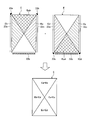
- FIG. 4 is an explanatory diagram for explaining a detection process when the reflection amount of the retroreflective plate provided on the lower frame is lowered.
- FIG. 5 is an explanatory diagram illustrating detection processing when the retroreflective plate provided on the lower frame is normal.
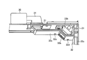
- FIG. 6 is a cross-sectional view of the deposit removal structure of the upper right detection unit as the light emitting / receiving device as seen obliquely.
- FIG. 7 is a schematic diagram showing the flow of wind.
- FIG. 1 is a schematic diagram showing a schematic configuration of an optical touch panel according to an embodiment of the present invention.
- FIG. 2 is a cross-sectional view showing the configuration of the retroreflective plate.
- FIG. 8 is a cross-sectional view of a modified example of the deposit removal structure of the upper right detection unit as the light receiving and emitting device as seen from an oblique direction.
- FIG. 9 is a schematic diagram illustrating a wind flow according to a modification.
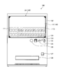
- FIG. 10 is a front view showing an appearance of a vending machine to which the optical touch panel according to the embodiment of the present invention is applied.
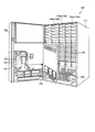
- FIG. 11 is a perspective view showing an internal configuration of the vending machine shown in FIG.
- FIG. 12 is a block diagram showing a control configuration of the vending machine shown in FIG.
- FIG. 13 is a diagram illustrating the configuration of the front surface of the outer door when the front surface of the display panel, the front surface of the dummy product display unit, and the front surface of the flat product display unit are used as detection areas of the touch detection unit.
- FIG. 1 is a schematic diagram showing a schematic configuration of an optical touch panel according to an embodiment of the present invention. As shown in FIG. 1, the touch detection unit 20 is provided on the surface of the display panel 10 having a display area corresponding to the detection area E.
- the touch detection unit 20 has a rectangular detection area E in a rectangular frame 21.
- the touch detection unit 20 includes retroreflective plates 22a, 22b, and 22c that generate reflected light on the axis of the input light on the inner side surface of the left frame, the inner side surface of the lower frame, and the inner side surface of the right frame.
- the touch detection unit 20 includes an upper left detection unit 23a, an upper right detection unit 23b, a lower left detection unit 23c, and a lower right detection unit 23d at the upper left corner, the upper right corner, the lower left corner, and the lower right corner of the frame 21, respectively.
- the lower left detection unit 23c and the lower right detection unit 23d are disposed at a distance d from the lower frame. This distance d is, for example, a value corresponding to the thickness of dust, snow, etc. deposited on the retroreflective plate 22b.
- the upper left detection part 23a irradiates infrared rays toward the retroreflective plates 22b and 22c, and receives the reflected light from the retroreflective plates 22b and 22c.
- the upper right detection unit 23b irradiates infrared rays toward the retroreflective plates 22a and 22b, and receives reflected light from the retroreflective plates 22a and 22b.
- the lower left detection part 23c irradiates infrared rays toward the retroreflective plate 22c, and receives reflected light from the retroreflective plate 22c.
- the lower right detector 23d irradiates infrared rays toward the retroreflective plate 22a and receives reflected light from the retroreflective plate 22a.
- the infrared irradiation part of the upper left detection part 23a, the upper right detection part 23b, the lower left detection part 23c, and the lower right detection part 23d is implement
- the infrared detection part of the upper left detection part 23a, the upper right detection part 23b, the lower left detection part 23c, and the lower right detection part 23d is implement
- the retroreflective plates 22a, 22b, and 22c are striped tapes that reflect infrared incident light as reflected light in the same direction as the incident light, as shown in FIG. As shown in FIG. 2, the specific retroreflecting plates 22 a, 22 b, and 22 c have a large number of fine glass beads 15 that are glass spheres scattered on the surface, and a reflective film 16 is formed on the lower surface of the glass beads 15. is doing.
- the retroreflecting plates 22a, 22b, and 22c can also be realized by a corner cube prism group in which a plurality of corner cube prisms are closely arranged in a plane.
- each corner cube prism is arranged densely.
- the corner cube prism is a triangular pyramid prism composed of three 90 degree right angles, and the reflected light always has a function of returning to the direction of the incident optical axis.
- the controller C is connected to the upper left detection unit 23a, the upper right detection unit 23b, the lower left detection unit 23c, the lower right detection unit 23d, and the display panel 10 and to an external device (not shown).
- the controller C includes an operation determination unit 1 and a display control unit 2.
- the operation determination unit 1 determines whether or not the operation object has been touched based on the detection image of the operation object by the touch detection unit 20. Note that the operation determination unit 1 specifies the coordinate position on the detection area E where the operation tool is touched.
- the display control unit 2 performs display processing on the display panel 10 according to the touch position of the operating body determined by the operation determination unit 1.
- the upper left detection unit 23a and the upper right detection unit 23b can detect the entire surface of the detection region E, respectively. Further, the lower left detection unit 23c can detect a region on the right side of the detection region E with respect to the diagonal line with the upper right detection unit 23b. Moreover, the lower right detection part 23d can detect the area
- the operation determination unit 1 specifies the position P in the detection region E based on the three detection images having shadows P1, P2, and P3.
- the specification of the position P can be performed by triangulation such as a forward intersection method using two or more detection images having shadows.
- the detection area of the upper right detection unit 23b is only the detection area Eb corresponding to the retroreflective plate 22a. Therefore, in the conventional optical touch panel having only the two detection units of the upper left detection unit 23a and the upper right detection unit 23b, when the reflection amount of the retroreflective plate 22b is reduced, the detection regions are the detection regions Ea and Eb. Only the detection area Eab, which is an overlapping area, was provided.
- a lower left detection unit 23c and a lower right detection unit 23d that do not use the retroreflective plate 22b are provided.
- detection areas Ec and Ed that are vertically symmetrical with respect to the detection areas Ea and Eb by the two detection units of the upper left detection unit 23a and the upper right detection unit 23b are formed.
- the four detections of the upper left detection unit 23a, the upper right detection unit 23b, the lower left detection unit 23c, and the lower right detection unit 23d even when the retroreflective plate 22b cannot be used, the four detections of the upper left detection unit 23a, the upper right detection unit 23b, the lower left detection unit 23c, and the lower right detection unit 23d.
- Two detection images can be obtained for the entire surface of the detection region E by the unit, and the touch position can be detected with high accuracy for the entire surface of the detection region E.
- the upper area obtained by dividing the detection area E by a diagonal line overlaps the detection areas Ea and Eb, and the left area overlaps the detection areas Eb and Ed.
- the detection areas Ea and Ec overlap in the area, and the detection areas Ec and Ed overlap in the lower area.
- the upper area E1 obtained by dividing the detection area E by a diagonal line overlaps the detection areas Ea and Eb, and the left area E2 is the detection area.
- two detection areas to be preferentially used in the touch position specifying process are set in advance.
- another detection area is used as an auxiliary to the touch position specifying process.
- two detection areas in each area shown in the lower part of FIG. 4 are set as priority detection areas.
- the detection regions Eb, Ed are set as the priority detection regions for the touch position specifying process among the detection regions Ea, Eb, Ed, and the detection region Ea is touched.
- It is set as an auxiliary detection area for position identification processing.
- a priority detection area may be used.
- the retroreflecting plate 22b is provided inside the lower frame.
- the retroreflecting plates 22a and 22c are provided, and the four upper left detection units 23a, the upper right detection unit 23b, and the lower left detection are provided.
- the part 23c and the lower right detection part 23d may be provided at the four corners of the frame 21, respectively.
- two or more detection images are detected on the entire detection region E by two detection units of the upper left detection unit 23a, the upper right detection unit 23b, the lower left detection unit 23c, and the lower right detection unit 23d. And the touch position of the operating tool can be detected.
- one detection region E is provided.
- a plurality of detection regions E may be formed by using the touch detection unit 20 as a multi-stage configuration.
- FIG. 6 is a cross-sectional view of the deposit removal structure of the upper right detection unit 23b as a light emitting / receiving device as seen obliquely.
- FIG. 7 is a schematic diagram showing the flow of wind.
- the upper right detection unit 23b is covered with a cover 32a.
- the cover 32a is shielded from the outside air by sandwiching the upper right detection part 23b with the frame 21.
- the cover 32a has an opening 32b in a portion corresponding to the light emitting surface 40 and the light receiving surface 41 of the upper right detection unit 23b.
- the cover 32a communicates with a duct 31 that supplies wind.
- the blower fan 30 supplies wind to the cover 32 a through the duct 31.
- the cover 32 is a cover that covers the retroreflective plate 22c.
- the cover 32a also has a duct function.
- the wind A supplied from the duct 31 passes through the front surface of the light emitting surface 40 and the light receiving surface 41 and flows toward the opening 32b. Thereby, deposits such as dust and water droplets adhering to the light emitting surface 40 and the light receiving surface 41 are removed. In particular, since the wind A flows away from the light emitting surface 40 and the light receiving surface 41, it is possible to reliably prevent the intrusion of foreign substances from the outside.
- FIG. 8 is a cross-sectional view of a modified example of the deposit removal structure of the upper right detection unit 23b serving as a light emitting / receiving device as viewed obliquely.
- FIG. 9 is a schematic diagram showing a wind flow according to a modification. As shown in FIGS. 8 and 9, in this modified example, the cover 32a is provided with sub-openings 32c and 32d adjacent to the opening 32b.
- the winds A2 and A3 are generated via the sub-openings 32c and 32d in parallel with the wind A1 passing through the opening 32b, and the intrusion of the adhering matter due to the entrainment wind generated in the vicinity of the opening 32b can be reliably suppressed.
- the adhering matter removal timing may include a clock (not shown) and drive the blower fan 30 for a predetermined time after a predetermined time has elapsed. Furthermore, a rain sensor (not shown) is provided, and the blower fan 30 may be driven during a period in which the rain sensor detects rain. With these configurations, it is possible to save energy and efficiently remove deposits.
- a vending machine that sells products such as canned beverages, bottled beverages, and plastic bottled beverages will be described as an example.
- the present invention is not limited to this.
- a cup that dispenses beverages into a cup The present invention can also be applied to a beverage vending machine and a vending machine that sells goods.
- FIG. 10 is a front view showing the appearance of a vending machine to which the above-described optical touch panel is applied.
- FIG. 11 is a perspective view showing an internal configuration of the vending machine shown in FIG.
- FIG. 12 is a block diagram showing a control configuration of the vending machine shown in FIG.
- This vending machine 100 is a vending machine that sells products such as canned beverages, bottled beverages, and plastic bottled beverages, and has a main body cabinet 101 as shown in FIG.
- the main body cabinet 101 is formed in a box shape having an open front by appropriately combining a plurality of steel plates, and the front opening of the main body cabinet 101 is closed by an openable / closable outer door 102.
- the interior of the main body cabinet 101 is defined by a machine room 103 and a product storage room 104.
- the product storage chamber 104 is further partitioned into three product storages 104a, 104b, and 104c by a heat insulating partition plate.
- the left-hand side product storage (hereinafter referred to as “left storage”) 104a and the central product storage (hereinafter referred to as “center storage”) 104b are: Switching between cold and hot is possible. And when the goods storage 104a (104b) is set to cooling, the inside of the goods storage 104a (104b) is cooled, and the goods stored in the goods storage 104a (104b) are cooled.
- the product storage case 104a (104b) when the product storage case 104a (104b) is set to warm, the inside of the product storage case 104a (104b) is heated, and the product stored in the product storage case 104a (104b) is heated.
- the right product storage (hereinafter referred to as “right storage”) 104c facing the front is a cooling-only storage, which cools the inside of the product storage 104c and cools the products stored in the product storage 104c.
- the product storage rack 105 is mounted on each of the product storage boxes 104a, 104b, and 104c.
- the merchandise storage rack 105 is provided with five passages (hereinafter referred to as “rack” for convenience) in the depth direction of the merchandise storage boxes 104a, 104b, and 104c. It is possible.
- a main door lock 121 is provided in the middle of the front right side of the outer door 102, and is locked in a state where the outer door 102 is closed.
- a display operation unit 120 (see FIG. 10) is provided at the upper front portion of the outer door 102.
- the display operation unit 120 is a combination of the large display panel 10 and the touch detection unit 20, and displays a sales display screen. On the sales display screen, products that can be sold are displayed, and the products are determined by at least the detection of the operation tool described above.
- a coin insertion slot 123 a bill insertion slot 124, a return lever 125, and an electronic money reader / writer 126 are provided in the middle of the outer door 102 below the display operation unit 120.
- the coin insertion slot 123 is an opening for receiving coins, and the coins inserted from the coin insertion slot 123 are accommodated in a coin mechanism (coin processing device) 131 (see FIG. 11) mounted inside the outer door 102. Is done.
- the coin mechanism 131 arranges the number of inserted various coins and transmits the coins to a main controller 140 (see FIG. 12), which will be described later, while paying out various coins according to a command from the main controller 140.
- the coin mechanism 131 mounted on the vending machine 100 has a self-monitoring function for monitoring its own state, and a cassette tube (not shown) containing coins is used to collect the coins stored therein. When the user removes or operates an inventory switch (not shown), the coin mechanism 131 transmits a message to that effect to the main controller 140 (to be described later).
- the banknote insertion slot 124 is an opening for receiving banknotes, and the banknote inserted from the banknote insertion slot 124 is accommodated in a bill validator (banknote processing device) 132 (see FIG. 11) mounted inside the outer door 102. Is done.
- the bill validator 132 organizes the number of inserted bills and transmits it to the main controller 140 (see FIG. 12), while paying out bills according to a command from the main controller 140.
- the bill validator 132 mounted on the vending machine 100 has a self-monitoring function for monitoring its own state, and a stacker (not shown) containing banknotes is collected in order to collect banknotes stored therein. When the opening operation is performed, the bill validator 132 transmits a message to that effect to the main controller 140 (to be described later).
- the return lever 125 is for instructing to interrupt the transaction.
- the transaction is interrupted, and change or the like is discharged to the return port 127.
- the electronic money reader / writer 126 identifies the card and performs settlement with the electronic money charged in the card.
- an outlet 128 is provided at a position below the outer door 102.
- the take-out port 128 is an opening for taking out the product carried out from the product storage rack 105.
- a remote controller 133 is disposed inside the outer door 102.
- the remote controller 133 is for performing various setting operations and various sales data confirmation operations, and includes a monitor (liquid crystal character display) on which various setting data and confirmation data are displayed in addition to operation keys and a cooling / warming switch. .
- the setting data set and input from the remote controller 133 is transmitted to the main controller 140, and the confirmation data transmitted from the main controller 140 is received.
- the vending machine 100 is provided with an operation key (replenishment operation key) that is operated when a product is replenished (loading), and when the operation key is operated, the remote controller 133 indicates that (input of a product replenishment operation). Is transmitted to the main controller 140 described later.
- a door switch 134 is provided inside the outer door 102.
- the door switch 134 is for detecting the open / closed state of the outer door 102 and is turned on when the outer door 102 is opened, and turned off when the outer door 102 is closed.
- the above-described coin mechanism 131, bill validator 132, and electronic money reader / writer 126 are connected to a main controller (main control unit) 140 via a line 141, and a display operation unit 120 (display panel). 10 and the touch detection unit 20) and the remote controller 133 are connected to the main controller 140 via a line 142.
- a main body control unit 144 is connected to the main controller 140 via a line 143.
- a cooling / heating device 145 and a carry-out device 146 are connected to the main body control unit 144, and the cooling / heating device 145 and the carry-out device 146 are controlled in accordance with instructions from the main controller 140.
- the cooling / heating device 145 is for managing the above-described commodity storages 104a, 104b, 104c in a set state, and cools the inside of the cooling-set commodity storages, while heating the product storages. Warm the inside.
- the carry-out device 146 is for managing bend solenoids and sold-out switches provided for each rack.
- the carry-out device 146 carries out products from the rack according to a carry-out command transmitted from the main controller 140 to the main body control unit 144, while When all the stored products are carried out, a sold-out signal is output to the main body control unit 144.
- the main controller 140 includes a control unit 150, an operation determination unit 1, and a display control unit 2.
- the control unit 150 centrally manages the electronic money reader / writer 126, the coin mechanism 131, the bill validator 132, the display operation unit 120 (the display panel 10 and the touch detection unit 20), the remote controller 133, the main body control unit 144, and the like. Control is performed based on various setting data stored in the storage unit.
- the main controller 140 determines that the electronic money reader / writer 126, the coin A money process is performed based on information of the mechanism 131 and the bill validator 132, and a product carry-out process corresponding to the determined position is performed via the main body control unit 144.
- the detection area of the touch detection unit 20 covers only a large display panel 10 such as a liquid crystal panel. However, as shown in FIG. In addition to the display panel 10, the detection area includes a front surface of a dummy product display unit 110 that displays a dummy that is a three-dimensional product and a front surface of a flat product display unit 111 on which the product is depicted in a plane. May be.
- the detection area of the touch detection unit 20 may be a combination of one or more of the front surface of the display panel 10, the front surface of the dummy product display unit 110, and the front surface of the flat product display unit 111.
- a product purchase guidance display may be displayed on the display panel 10 or voice guidance may be performed.
- the touch detection unit 20 does not require a touch sensor or a protective film to be attached to the surface of the display panel 10, so various display units (display panel 10, dummy An arbitrary area in front of the product display unit 110 and the flat product display unit 111) can be easily set as a detection region.
- the structure of the deposit removing apparatus for the light receiving and emitting device described above is not limited to the case where the detection units are provided at the four corners of the frame 21, but can also be applied to the case where two detection units are provided in the frame 21.
Landscapes
- Engineering & Computer Science (AREA)
- General Engineering & Computer Science (AREA)
- Theoretical Computer Science (AREA)
- Human Computer Interaction (AREA)
- Physics & Mathematics (AREA)
- General Physics & Mathematics (AREA)
- Control Of Vending Devices And Auxiliary Devices For Vending Devices (AREA)
Abstract
外部から受発光デバイスの発光面及び受光面に向かう付着物の侵入を確実に防止することができる受発光デバイスの付着物除去装置及び自動販売機を提供することを目的とする。このため、光を出射する発光面40と光を受光する受光面41とを有した受発光デバイスである右上検出部23bと、発光面40及び受光面41に対向する部分に開口32bを形成して右上検出部23bを覆うカバー32aと、カバー32a内に風Aを供給するダクト31と、ダクト31に風Aを供給する送風ファン30と、を備え、ダクト31から供給された風Aを発光面40及び受光面41から開口32bに向けて流す。
Description
本発明は、外部から受発光デバイスの発光面及び受光面に向かう付着物の侵入を確実に防止することができる受発光デバイスの付着物除去装置及び自動販売機に関する。
近年の自動販売機では、前面扉に組み込んだディスプレイを用いて商品見本を画像として表示し、タッチパネルなどを用いて商品選択を行うようにしている(特許文献1参照)。このディスプレイ及びタッチパネルを用いることによって、自動販売機の拡張化を図ることができる。
一方、特許文献2には、タッチパネルの一例として、静電容量方式、光学方式、超音波方式が記載されている。また、特許文献3には、検出面内の所定の位置ごとに予め設定されている検出基準を用いて、検出面に接触または近接する指示体の位置を検出するものが記載されている。
特許文献4には、光遮断方式による位置検出に関するもので、光を投光及び受光する光学センサを検出領域の一辺に配置し、他の辺には薄い光再帰反射枠を設けるものが記載されている。そして、特許文献4には、周囲光の影響を少なくするために、光源を点滅させて、点灯時と消灯時の信号の差分をとるようにしている。
特許文献5には、座標面上で直接的または間接的に放射光を発する指示体の位置座標を求めるため、該座標面の周辺に配置され該放射光を受光して電気信号に変換する検出手段と、該検出手段の視野を該座標面から所定高さ以下に制限して受光可能な放射光の範囲を該座標面に対して平行化する光学手段と、該座標面の周囲を囲むように配置され該視野から放射光以外の不要光を除去する遮蔽枠などの遮蔽手段とを有するものが記載されている。
光学式タッチパネルには、矩形の枠内の内側に再帰反射板を配置するとともに、枠の左上隅及び右上隅に、赤外線をそれぞれ右斜め下方側及び左斜め下方側に照射して再帰反射板からの戻り光を検出する左上検出部と右上検出部とを設けるものがある。光学式タッチパネルは、左上検出部及び右上検出部が検出する再帰反射板からの戻り光の影位置によって操作体のタッチを検出している。
このような光学式タッチパネルを自動販売機の正面パネルなどに鉛直配置する場合、光学式タッチパネルは、屋外に配置されることから、左上検出部及び右上検出部の発光面及び受光面、及び再帰反射板が外気に曝され、塵や水滴などの付着物が付着し、検出精度が劣化する場合がある。これに対処するため、左上検出部及び右上検出部の発光面及び受光面、及び再帰反射板にカバーを被せ、枠とカバーとで外気から遮断し、塵や水滴などが付着しないようにすることが考えられる。さらに、左上検出部及び右上検出部の発光面及び受光面の前面に位置するカバー表面に平行な風を当てて、塵や水滴などの付着物が発光面及び受光面に対応するカバー表面に付着することを防止することが考えられる。
しかし、カバー表面に平行な風を当てるエアーカーテン方式では、発光面及び受光面に対するエアーカーテンの幅が狭いため、外部から発光面及び受光面側に向かう付着物を抑えきれない場合がある。
本発明は、上記に鑑みてなされたものであって、外部から受発光デバイスの発光面及び受光面に向かう付着物の侵入を確実に防止することができる受発光デバイスの付着物除去装置及び自動販売機を提供することを目的とする。
上述した課題を解決し、目的を達成するために、本発明にかかる受発光デバイスの付着物除去装置は、光を出射する発光面と光を受光する受光面とを有した受発光デバイスと、前記発光面及び前記受光面に対向する部分に開口を形成して前記受発光デバイスを覆うカバーと、前記カバー内に風を供給するダクトと、前記ダクトに風を供給する送風ファンと、を備え、前記ダクトから供給された風を前記発光面及び前記受光面から前記開口に向けて流すことを特徴とする。
また、本発明にかかる受発光デバイスの付着物除去装置は、上記の発明において、前記カバーは、前記開口に隣接してサブ開口を形成したことを特徴とする。
また、本発明にかかる受発光デバイスの付着物除去装置は、上記の発明において、所定時間を計時する時計を備え、前記所定時間が経過するごとに、前記送風ファンを駆動することを特徴とする。
また、本発明にかかる受発光デバイスの付着物除去装置は、上記の発明において、雨センサを備え、前記雨センサが雨を検出した場合、前記送風ファンを駆動することを特徴とする。
また、本発明にかかる自動販売機は、上記の発明の受発光デバイスの付着物除去装置を備えた光学式タッチパネルを自動販売機の外扉に設けたことを特徴とする。
本発明によれば、ダクトから供給された風を受発光デバイスの発光面及び受光面からカバーの開口に向けて流すようにしているので、外部からの付着物の侵入を確実に防止することができる。
以下、添付図面を参照してこの発明を実施するための形態について説明する。
(光学式タッチパネルの構成)
図1は、本発明の実施の形態である光学式タッチパネルの概要構成を示す模式図である。図1に示すように、タッチ検出部20は、検出領域Eに対応する表示領域を有した表示パネル10の面上に設けられる。
図1は、本発明の実施の形態である光学式タッチパネルの概要構成を示す模式図である。図1に示すように、タッチ検出部20は、検出領域Eに対応する表示領域を有した表示パネル10の面上に設けられる。
タッチ検出部20は、矩形の枠21内に矩形の検出領域Eを有する。タッチ検出部20は、枠21の左枠内部側面、下枠内部側面、右枠内部側面に、それぞれ入力光の軸に反射光を生成する再帰反射板22a,22b,22cを有する。また、タッチ検出部20は、枠21の左上隅、右上隅、左下隅、及び、右下隅に、それぞれ左上検出部23a、右上検出部23b、左下検出部23c、右下検出部23dを有する。なお、左下検出部23c及び右下検出部23dは、下枠から距離d、上側に配置される。この距離dは、例えば、塵や雪などが再帰反射板22b上に堆積した厚さに対応する値である。
左上検出部23aは、再帰反射板22b,22cに向けて赤外線を照射し、再帰反射板22b,22cからの反射光を受光する。右上検出部23bは、再帰反射板22a,22bに向けて赤外線を照射し、再帰反射板22a,22bからの反射光を受光する。左下検出部23cは、再帰反射板22cに向けて赤外線を照射し、再帰反射板22cからの反射光を受光する。右下検出部23dは、再帰反射板22aに向けて赤外線を照射し、再帰反射板22aからの反射光を受光する。なお、左上検出部23a、右上検出部23b、左下検出部23c、右下検出部23dの赤外線照射部は、例えば赤外線LEDによって実現される。また、左上検出部23a、右上検出部23b、左下検出部23c、右下検出部23dの赤外線検出部は、例えば赤外線イメージセンサーによって実現される。すなわち、左上検出部23a、右上検出部23b、左下検出部23c、右下検出部23dは、赤外線の受発光デバイスである。
再帰反射板22a,22b,22cは、ストライプ状のテープであり、図2に示すように、赤外線の入射光を、入射光と同じ方向に反射光として反射する。具体的な再帰反射板22a,22b,22cは、図2に示すように、ガラス球である微細な多数のガラスビーズ15を面上に散りばめるとともに、ガラスビーズ15の下面に反射膜16を形成している。なお、再帰反射板22a,22b,22cは、複数のコーナーキューブプリズムを密に平面配置したコーナーキューブプリズム群によっても実現することができる。この平面配置は、各コーナーキューブプリズムの三角形の入出射面を密に配置することが好ましい。コーナーキューブプリズムは、90度の直角を3つ合成した三角錐のプリズムであり、反射光は、必ず入射した光軸の方向に戻る機能を有する。
コントローラCは、左上検出部23a、右上検出部23b、左下検出部23c、右下検出部23d、及び、表示パネル10に接続されるとともに、図示しない外部装置に接続される。コントローラCは、操作判定部1及び表示制御部2を有する。操作判定部1は、タッチ検出部20による操作体の検出画像をもとに、操作体のタッチがあったか否かを判定する。なお、操作判定部1は、操作体のタッチがあった検出領域E上の座標位置を特定する。表示制御部2は、表示パネル10に対して、操作判定部1が判定した操作体のタッチ位置に応じた表示処理を行う。
(タッチ検出部による検出動作)
まず、左上検出部23a及び右上検出部23bは、それぞれ検出領域Eの全面を検出できる。また、左下検出部23cは、検出領域Eのうち、右上検出部23bとの対角線よりも右側の領域を検出できる。また、右下検出部23dは、検出領域Eのうち、左上検出部23aとの対角線よりも左側の領域を検出できる。例えば、図1に示すように、検出領域Eの右側の位置Pに操作体のタッチがあった場合、左上検出部23aは、図3に示す検出画像を得ることができる。この検出画像中には、操作体の存在によって赤外線が戻ってこない影P1が存在する。同様にして、右上検出部23bは、影P2が存在する検出画像を得ることができる。また、左下検出部23cは、影P3が存在する検出画像を得ることができる。なお、右下検出部23dは、位置Pが検出領域外であるので影のある検出画像を得ることができない。操作判定部1は、影P1,P2,P3をそれぞれ持つ3つの検出画像をもとに、検出領域E内の位置Pを特定する。この位置Pの特定は、影をもつ2つ以上の検出画像を用い、前方交会法などの三角測量によって行うことができる。
まず、左上検出部23a及び右上検出部23bは、それぞれ検出領域Eの全面を検出できる。また、左下検出部23cは、検出領域Eのうち、右上検出部23bとの対角線よりも右側の領域を検出できる。また、右下検出部23dは、検出領域Eのうち、左上検出部23aとの対角線よりも左側の領域を検出できる。例えば、図1に示すように、検出領域Eの右側の位置Pに操作体のタッチがあった場合、左上検出部23aは、図3に示す検出画像を得ることができる。この検出画像中には、操作体の存在によって赤外線が戻ってこない影P1が存在する。同様にして、右上検出部23bは、影P2が存在する検出画像を得ることができる。また、左下検出部23cは、影P3が存在する検出画像を得ることができる。なお、右下検出部23dは、位置Pが検出領域外であるので影のある検出画像を得ることができない。操作判定部1は、影P1,P2,P3をそれぞれ持つ3つの検出画像をもとに、検出領域E内の位置Pを特定する。この位置Pの特定は、影をもつ2つ以上の検出画像を用い、前方交会法などの三角測量によって行うことができる。
(再帰反射板22bの反射量低下時の検出動作)
ところで、図4に示すように、検出領域Eは、前面が開放された層状空間であるため、再帰反射板22b上に塵や雪などが堆積しやすい状態となっている。このため、再帰反射板22b上に塵や雪などが堆積すると、再帰反射板22bからの反射光の反射量が低下するため、検出画像中の影の判別が困難となって検出精度が低下する。すなわち、図4に示すように、左上検出部23aの検出領域は、再帰反射板22cに対応する検出領域Eaのみとなる。同様に、右上検出部23bの検出領域は、再帰反射板22aに対応する検出領域Ebのみとなる。したがって、左上検出部23a及び右上検出部23bの2つの検出部のみを有した従来の光学式タッチパネルは、再帰反射板22bの反射量低下が生じた場合、検出領域は、検出領域Ea,Ebの重複領域である検出領域Eabのみとなっていた。
ところで、図4に示すように、検出領域Eは、前面が開放された層状空間であるため、再帰反射板22b上に塵や雪などが堆積しやすい状態となっている。このため、再帰反射板22b上に塵や雪などが堆積すると、再帰反射板22bからの反射光の反射量が低下するため、検出画像中の影の判別が困難となって検出精度が低下する。すなわち、図4に示すように、左上検出部23aの検出領域は、再帰反射板22cに対応する検出領域Eaのみとなる。同様に、右上検出部23bの検出領域は、再帰反射板22aに対応する検出領域Ebのみとなる。したがって、左上検出部23a及び右上検出部23bの2つの検出部のみを有した従来の光学式タッチパネルは、再帰反射板22bの反射量低下が生じた場合、検出領域は、検出領域Ea,Ebの重複領域である検出領域Eabのみとなっていた。
この実施の形態では、再帰反射板22bを用いない、左下検出部23c及び右下検出部23dを設けている。これにより、図4の上部右側に示すように、左上検出部23a及び右上検出部23bの2つの検出部による検出領域Ea,Ebに対して上下対称の検出領域Ec,Edが形成される。この結果、図4の下部に示すように、再帰反射板22bが使用できない状態であっても、左上検出部23a、右上検出部23b、左下検出部23c、及び右下検出部23dの4つの検出部によって検出領域Eの全面に対して2つの検出画像を得ることができ、検出領域Eの全面に対してタッチ位置を精度高く検出することができる。具体的に、図4下部に示したように、検出領域Eを対角線で分割された上側の領域は検出領域Ea,Ebが重複し、左側の領域は検出領域Eb,Edが重複し、右側の領域は検出領域Ea,Ecが重複し、下側の領域は検出領域Ec,Edが重複している。
(再帰反射板22bの反射量正常時の検出動作)
再帰反射板22bが正常に反射している場合、図5に示すように、検出領域Eを対角線で分割された上側の領域E1は検出領域Ea,Ebが重複し、左側の領域E2は検出領域Ea,Eb,Edの3つの領域が重複し、右側の領域E3は検出領域Ea,Eb,Ecの3つの領域が重複し、下側の領域E4は検出領域Ea,Eb,Ec,Edの4つの領域が重複している。
再帰反射板22bが正常に反射している場合、図5に示すように、検出領域Eを対角線で分割された上側の領域E1は検出領域Ea,Ebが重複し、左側の領域E2は検出領域Ea,Eb,Edの3つの領域が重複し、右側の領域E3は検出領域Ea,Eb,Ecの3つの領域が重複し、下側の領域E4は検出領域Ea,Eb,Ec,Edの4つの領域が重複している。
この場合、3つ以上の検出領域が重複している領域では、予め、タッチ位置の特定処理で優先して用いる2つの検出領域を設定しておく。そして、他の検出領域をタッチ位置の特定処理の補助的なものとして用いる。例えば、図4下部に示した各領域の2つの検出領域を優先検出領域として設定しておく。例えば、図5において、左側の領域E2は、検出領域Ea,Eb,Edのうち、検出領域Eb,Edをタッチ位置の特定処理のための優先検出領域として設定しておき、検出領域Eaをタッチ位置の特定処理のための補助検出領域として設定しておく。補助検出領域を用いる場合、精度の高いタッチ位置特定を行うことができる。一方、迅速なタッチ位置特定を行う場合には、優先検出領域を用いればよい。
なお、上述した実施の形態では、下部枠の内側に再帰反射板22bを設けているが、少なくとも、再帰反射板22a,22cを設けるとともに、4つの左上検出部23a、右上検出部23b、左下検出部23c、右下検出部23dをそれぞれ枠21の四隅に設ければよい。これによって、図4に示すように、検出領域Eの全面において、左上検出部23a、右上検出部23b、左下検出部23c、右下検出部23dのうちの2つの検出部によって2以上の検出画像が得られ、操作体のタッチ位置を検出することができる。
また、上述した実施の形態では、1つの検出領域Eを有するものであったが、タッチ検出部20を多段構成として、複数層の検出領域Eを形成してもよい。
(受発光デバイスの付着物除去構造)
図6は、受発光デバイスとしての右上検出部23bの付着物除去構造を斜めからみた断面図である。また、図7は、風の流れを示す模式図である。図6及び図7に示すように、右上検出部23bは、カバー32aに覆われている。カバー32aは、右上検出部23bを枠21とで挟み込むことで外気から遮断している。ただし、カバー32aは、右上検出部23bの発光面40及び受光面41に対応する部分に開口32bを形成している。また、カバー32aは、風を供給するダクト31に連通している。送風ファン30は、ダクト31を介してカバー32aに風を供給する。なお、カバー32は、再帰反射板22cを覆うカバーである。また、カバー32aは、ダクトの機能も有している。
図6は、受発光デバイスとしての右上検出部23bの付着物除去構造を斜めからみた断面図である。また、図7は、風の流れを示す模式図である。図6及び図7に示すように、右上検出部23bは、カバー32aに覆われている。カバー32aは、右上検出部23bを枠21とで挟み込むことで外気から遮断している。ただし、カバー32aは、右上検出部23bの発光面40及び受光面41に対応する部分に開口32bを形成している。また、カバー32aは、風を供給するダクト31に連通している。送風ファン30は、ダクト31を介してカバー32aに風を供給する。なお、カバー32は、再帰反射板22cを覆うカバーである。また、カバー32aは、ダクトの機能も有している。
ダクト31から供給された風Aは、発光面40及び受光面41の前面を通り、開口32bに向けて流れる。これによって、発光面40及び受光面41に付着する塵や水滴などの付着物は除去される。特に、風Aは、発光面40及び受光面41から離れるように流れるので、外部からの付着物の侵入を確実に防止することができる。
(受発光デバイスの付着物除去構造の変形例)
図8は、受発光デバイスとしての右上検出部23bの付着物除去構造の変形例を斜めからみた断面図である。また、図9は、変形例による風の流れを示す模式図である。図8及び図9に示すように、この変形例では、カバー32aに、開口32bに隣接するサブ開口32c,32dを設けている。これによって、開口32bを通る風A1に平行してサブ開口32c,32dを介した風A2,A3が生じ、開口32b近傍に生じる巻き込み風による付着物の侵入を確実に抑えることができる。
図8は、受発光デバイスとしての右上検出部23bの付着物除去構造の変形例を斜めからみた断面図である。また、図9は、変形例による風の流れを示す模式図である。図8及び図9に示すように、この変形例では、カバー32aに、開口32bに隣接するサブ開口32c,32dを設けている。これによって、開口32bを通る風A1に平行してサブ開口32c,32dを介した風A2,A3が生じ、開口32b近傍に生じる巻き込み風による付着物の侵入を確実に抑えることができる。
(付着物除去タイミング)
この付着物除去タイミングは、図示しない時計を備え、所定時間経過後に一定時間、送風ファン30を駆動すればよい。さらに、図示しない雨センサを備え、雨センサが雨を検出している期間中、送風ファン30を駆動すればよい。これらの構成によって、省エネルギー化を図って、効率的な付着物除去を行うことができる。
この付着物除去タイミングは、図示しない時計を備え、所定時間経過後に一定時間、送風ファン30を駆動すればよい。さらに、図示しない雨センサを備え、雨センサが雨を検出している期間中、送風ファン30を駆動すればよい。これらの構成によって、省エネルギー化を図って、効率的な付着物除去を行うことができる。
(自動販売機への適用)
つぎに、上述した光学式タッチパネルを自動販売機に適用した場合について説明する。ここでは、缶入り飲料、ビン入り飲料、ペットボトル入り飲料などの商品を販売する自動販売機を例に説明するが、これに限定されるものではなく、たとえば、カップに飲料を注出するカップ式飲料自動販売機や物品を販売する自動販売機にも適用可能である。
つぎに、上述した光学式タッチパネルを自動販売機に適用した場合について説明する。ここでは、缶入り飲料、ビン入り飲料、ペットボトル入り飲料などの商品を販売する自動販売機を例に説明するが、これに限定されるものではなく、たとえば、カップに飲料を注出するカップ式飲料自動販売機や物品を販売する自動販売機にも適用可能である。
図10は、上述した光学式タッチパネルを適用した自動販売機の外観を示す正面図である。図11は、図10に示した自動販売機の内部構成を示す斜視図である。また、図12は、図10に示した自動販売機の制御構成を示すブロック図である。
この自動販売機100は、缶入り飲料、ビン入り飲料、ペットボトル入り飲料などの商品を販売する自動販売機であって、図11に示すように、本体キャビネット101を有している。本体キャビネット101は、複数の鋼板を適宜組み合わせることにより、前面が開口した箱状に構成してあり、本体キャビネット101の前面開口は、開閉可能な外扉102によって閉塞される。
本体キャビネット101の内部は、機械室103と商品収容室104とに画成されている。また、商品収容室104は、断熱仕切板によってさらに三つの商品収納庫104a,104b,104cに仕切られている。これら三つの商品収納庫104a,104b,104cのうち、正面向かって左側の商品収納庫(以下、「左庫」という)104aと中央の商品収納庫(以下「中庫」という)104bとは、冷温切り替えが可能である。そして、商品収納庫104a(104b)を冷却に設定した場合には、商品収納庫104a(104b)の内部を冷却し、商品収納庫104a(104b)に収納した商品を冷却する。一方、商品収納庫104a(104b)を加温に設定した場合には、商品収納庫104a(104b)の内部を加温し、商品収納庫104a(104b)に収納した商品を加温する。また、正面向かって右側の商品収納庫(以下、「右庫」という)104cは、冷却専用庫であり、商品収納庫104cの内部を冷却し、商品収納庫104cに収納した商品を冷却する。
商品収納庫104a,104b,104cには、それぞれ商品収納ラック105が搭載してある。自動販売機100は、左庫104aと右庫104cの幅方向に二列の商品収納ラック105が搭載してあり、中庫104bの幅方向に一列の商品収納ラック105が搭載してある。また、商品収納ラック105には、商品収納庫104a,104b,104cの奥行き方向に五つの通路(以下、この通路を便宜上、「ラック」と称する)が設けてあり、各通路には商品が収納可能となっている。
図10に示すように、外扉102の前面右側中程には、メインドアロック121が設けてあり、外扉102を閉塞した状態で施錠される。また、外扉102の前面上方部には、表示操作部120(図10参照)が設けてある。表示操作部120は、大型の表示パネル10とタッチ検出部20とを組み合わせたものであり、販売表示画面が表示される。販売表示画面には、販売可能な商品が表示され、少なくとも上述した操作体の検出によって商品が決定される。
また、表示操作部120の下方となる外扉102の中程には、硬貨投入口123、紙幣挿入口124、返却レバー125、電子マネーリーダライタ126が設けてある。
硬貨投入口123は、硬貨を受け付けるための開口であって、硬貨投入口123から投入された硬貨は、外扉102の内側に搭載したコインメカニズム(硬貨処理装置)131(図11参照)に収容される。コインメカニズム131は、各種硬貨の投入枚数を整理し、後述するメインコントローラ140(図12参照)に送信する一方、メインコントローラ140からの指令に従い、各種硬貨を払い出す。また、自動販売機100に搭載したコインメカニズム131は、自己の状態を監視する自己監視機能を備えており、内部に収納した硬貨を回収するために、硬貨を収容したカセットチューブ(図示せず)を取り外した場合や、インベントリスイッチ(図示せず)を操作した場合には、コインメカニズム131がその旨(硬貨の回収操作入力)を後述するメインコントローラ140に送信する。
紙幣挿入口124は、紙幣を受け付けるための開口であって、紙幣挿入口124から挿入された紙幣は、外扉102の内側に搭載したビルバリデータ(紙幣処理装置)132(図11参照)に収容される。ビルバリデータ132は、紙幣の投入枚数を整理し、メインコントローラ140(図12参照)に送信する一方、メインコントローラ140からの指令に従い、紙幣を払い出す。また、自動販売機100に搭載したビルバリデータ132は、自己の状態を監視する自己監視機能を備えており、内部に収納した紙幣を回収するために、紙幣を収容したスタッカ(図示せず)を開放操作した場合には、ビルバリデータ132がその旨(紙幣の回収操作入力)を後述するメインコントローラ140に送信する。
返却レバー125は、取引の中断を指示するためのもので、返却レバー125が操作されると、取引が中断され、釣り銭等を返却口127に放出する。電子マネーリーダライタ126は、カードを識別し、カードにチャージされた電子マネーにより決済を実行する。
また、外扉102の下方となる位置には、取出口128が設けてある。取出口128は、商品収納ラック105から搬出された商品を取り出すための開口である。
また、外扉102の内側には、リモコン133が配設してある。リモコン133は、各種設定操作、各種売上データの確認操作をおこなうためのもので、操作キー、冷温切替スイッチのほか、各種設定データや確認データが表示されるモニタ(液晶キャラクタディスプレイ)を備えている。そして、リモコン133から設定入力された設定データはメインコントローラ140に送信され、メインコントローラ140から送信された確認データを受信する。また、自動販売機100は、商品を補充(ローディング)する場合に操作する操作キー(補充操作キー)が設けてあり、当該操作キーを操作すると、リモコン133がその旨(商品の補充操作入力)を後述するメインコントローラ140に送信する。
また、外扉102の内側には、ドアスイッチ134が設けてある。ドアスイッチ134は、外扉102の開閉状態を検出するためのもので、外扉102を開放した場合にオンとなり、閉塞した場合にオフとなる。
図12に示すように、上述したコインメカニズム131、ビルバリデータ132、電子マネーリーダライタ126は、ライン141を介してメインコントローラ(主制御部)140に接続してあり、表示操作部120(表示パネル10およびタッチ検出部20)、リモコン133は、ライン142を介してメインコントローラ140に接続してある。また、メインコントローラ140には、ライン143を介して本体制御部144が接続してある。
本体制御部144には、上述したドアスイッチ134のほか、冷熱装置145、搬出装置146が接続してあり、メインコントローラ140からの指令に従って冷熱装置145、搬出装置146を制御する。
冷熱装置145は、上述した商品収納庫104a,104b,104cを設定された状態に管理するためのもので、冷却設定された商品収納庫の内部を冷却する一方、加温設定された商品収納庫の内部を加温する。
搬出装置146は、ラックごとに設けられたベンドソレノイド、売切スイッチを管理するためのもので、メインコントローラ140から本体制御部144に送信された搬出命令に従ってラックから商品を搬出する一方、ラックに収納された商品のすべてを搬出した場合に売切信号を本体制御部144に出力する。
なお、図12に示すように、メインコントローラ140は、制御部150、操作判定部1、表示制御部2を備えている。
制御部150は、電子マネーリーダライタ126、コインメカニズム131、ビルバリデータ132、表示操作部120(表示パネル10及びタッチ検出部20)、リモコン133、本体制御部144等を集中管理するもので、図示しない記憶部に記憶された各種設定データに基づいて制御する。
メインコントローラ140は、操作判定部1がタッチ検出部20の検出結果をもとに、操作体のタッチ操作によって商品等に対する決定操作が行われたものと判定した場合、電子マネーリーダライタ126、コインメカニズム131、ビルバリデータ132の情報をもとに金銭処理を行うとともに、この決定操作された位置に対応する商品の搬出処理を、本体制御部144を介して行う。
(自動販売機におけるタッチ検出部の検出領域)
図10に示した自動販売機100では、タッチ検出部20の検出領域が、液晶パネルなどの大型の表示パネル10のみをカバーするようにしていたが、図13に示すように、タッチ検出部20は、表示パネル10に加えて、立体的な商品であるダミーを展示するダミー商品展示部110の前面、及び平面的に商品が描かれた平面商品表示部111の前面を検出領域に含めるようにしてもよい。また、タッチ検出部20の検出領域は、表示パネル10の前面、ダミー商品展示部110の前面、平面商品表示部111の前面のいずれ1以上の組み合わせとしてもよい。なお、ダミー商品展示部110の前面、平面商品表示部111の前面を検出領域とする場合、商品購入のガイダンス表示を表示パネル10上に表示してもよいし、音声ガイダンスを行ってもよい。
図10に示した自動販売機100では、タッチ検出部20の検出領域が、液晶パネルなどの大型の表示パネル10のみをカバーするようにしていたが、図13に示すように、タッチ検出部20は、表示パネル10に加えて、立体的な商品であるダミーを展示するダミー商品展示部110の前面、及び平面的に商品が描かれた平面商品表示部111の前面を検出領域に含めるようにしてもよい。また、タッチ検出部20の検出領域は、表示パネル10の前面、ダミー商品展示部110の前面、平面商品表示部111の前面のいずれ1以上の組み合わせとしてもよい。なお、ダミー商品展示部110の前面、平面商品表示部111の前面を検出領域とする場合、商品購入のガイダンス表示を表示パネル10上に表示してもよいし、音声ガイダンスを行ってもよい。
タッチ検出部20は、従来の抵抗膜方式や静電容量方式のタッチパネルと異なり、表示パネル10の表面にタッチセンサーや保護膜を張り付ける必要がないため、各種の表示部(表示パネル10、ダミー商品展示部110、平面商品表示部111)の前面の任意領域を簡易に検出領域とすることができる。
なお、上述した受発光デバイスの付着物除去装置の構成は、枠21の四隅に検出部を設けた場合に限らず、枠21に2つの検出部を設けた場合にも適用できる。
1 操作判定部
2 表示制御部
10 表示パネル
15 ガラスビーズ
16 反射膜
20 タッチ検出部
21 枠
22a,22b,22c 再帰反射板
23a 左上検出部
23b 右上検出部
23c 左下検出部
23d 右下検出部
30 送風ファン
31 ダクト
32,32a カバー
32b 開口
32c,32d サブ開口
40 発光面
41 受光面
100 自動販売機
101 本体キャビネット
102 外扉
103 機械室
104 商品収容室
105 商品収納ラック
110 ダミー商品展示部
111 平面商品表示部
120 表示操作部
121 メインドアロック
123 硬貨投入口
124 紙幣挿入口
125 返却レバー
126 電子マネーリーダライタ
127 返却口
128 取出口
131 コインメカニズム
132 ビルバリデータ
133 リモコン
134 ドアスイッチ
140 メインコントローラ
141~143 ライン
144 本体制御部
145 冷熱装置
146 搬出装置
150 制御部
A,A1~A3 風
d 距離
E 検出領域
P 位置
P1,P2,P3 影
2 表示制御部
10 表示パネル
15 ガラスビーズ
16 反射膜
20 タッチ検出部
21 枠
22a,22b,22c 再帰反射板
23a 左上検出部
23b 右上検出部
23c 左下検出部
23d 右下検出部
30 送風ファン
31 ダクト
32,32a カバー
32b 開口
32c,32d サブ開口
40 発光面
41 受光面
100 自動販売機
101 本体キャビネット
102 外扉
103 機械室
104 商品収容室
105 商品収納ラック
110 ダミー商品展示部
111 平面商品表示部
120 表示操作部
121 メインドアロック
123 硬貨投入口
124 紙幣挿入口
125 返却レバー
126 電子マネーリーダライタ
127 返却口
128 取出口
131 コインメカニズム
132 ビルバリデータ
133 リモコン
134 ドアスイッチ
140 メインコントローラ
141~143 ライン
144 本体制御部
145 冷熱装置
146 搬出装置
150 制御部
A,A1~A3 風
d 距離
E 検出領域
P 位置
P1,P2,P3 影
Claims (5)
- 光を出射する発光面と光を受光する受光面とを有した受発光デバイスと、
前記発光面及び前記受光面に対向する部分に開口を形成して前記受発光デバイスを覆うカバーと、
前記カバー内に風を供給するダクトと、
前記ダクトに風を供給する送風ファンと、
を備え、
前記ダクトから供給された風を前記発光面及び前記受光面から前記開口に向けて流すことを特徴とする受発光デバイスの付着物除去装置。 - 前記カバーは、前記開口に隣接してサブ開口を形成したことを特徴とする請求項1に記載の受発光デバイスの付着物除去装置。
- 所定時間を計時する時計を備え、
前記所定時間が経過するごとに、前記送風ファンを駆動することを特徴とする請求項1または2に記載の受発光デバイスの付着物除去装置。 - 雨センサを備え、
前記雨センサが雨を検出した場合、前記送風ファンを駆動することを特徴とする請求項1~3のいずれか一つに記載の受発光デバイスの付着物除去装置。 - 請求項1~4のいずれか一つに記載の受発光デバイスの付着物除去装置を備えた光学式タッチパネルを自動販売機の外扉に設けたことを特徴とする自動販売機。
Priority Applications (1)
| Application Number | Priority Date | Filing Date | Title |
|---|---|---|---|
| JP2017529500A JP6601497B2 (ja) | 2015-07-17 | 2016-06-07 | 受発光デバイスの付着物除去装置及び自動販売機 |
Applications Claiming Priority (2)
| Application Number | Priority Date | Filing Date | Title |
|---|---|---|---|
| JP2015-143459 | 2015-07-17 | ||
| JP2015143459 | 2015-07-17 |
Publications (1)
| Publication Number | Publication Date |
|---|---|
| WO2017013958A1 true WO2017013958A1 (ja) | 2017-01-26 |
Family
ID=57835031
Family Applications (1)
| Application Number | Title | Priority Date | Filing Date |
|---|---|---|---|
| PCT/JP2016/066842 Ceased WO2017013958A1 (ja) | 2015-07-17 | 2016-06-07 | 受発光デバイスの付着物除去装置及び自動販売機 |
Country Status (2)
| Country | Link |
|---|---|
| JP (1) | JP6601497B2 (ja) |
| WO (1) | WO2017013958A1 (ja) |
Citations (3)
| Publication number | Priority date | Publication date | Assignee | Title |
|---|---|---|---|---|
| JP2003029571A (ja) * | 2001-07-19 | 2003-01-31 | Hitachi Koki Co Ltd | 定着装置 |
| JP2006172470A (ja) * | 2004-12-16 | 2006-06-29 | Agilent Technol Inc | 高解像度光学タッチ位置決定システムのためのシステム及び方法 |
| JP3134814U (ja) * | 2007-06-14 | 2007-08-23 | 日立ソフトウエアエンジニアリング株式会社 | 座標検出装置 |
Family Cites Families (5)
| Publication number | Priority date | Publication date | Assignee | Title |
|---|---|---|---|---|
| JPH11232537A (ja) * | 1998-02-17 | 1999-08-27 | Japan Tobacco Inc | 自動販売機 |
| JP3817069B2 (ja) * | 1998-05-19 | 2006-08-30 | 株式会社リコー | 座標入力装置 |
| JP2007072506A (ja) * | 2005-09-02 | 2007-03-22 | Canon Inc | 座標入力装置 |
| US8902193B2 (en) * | 2008-05-09 | 2014-12-02 | Smart Technologies Ulc | Interactive input system and bezel therefor |
| JP5884395B2 (ja) * | 2011-10-14 | 2016-03-15 | 富士電機株式会社 | 自動販売機 |
-
2016
- 2016-06-07 JP JP2017529500A patent/JP6601497B2/ja active Active
- 2016-06-07 WO PCT/JP2016/066842 patent/WO2017013958A1/ja not_active Ceased
Patent Citations (3)
| Publication number | Priority date | Publication date | Assignee | Title |
|---|---|---|---|---|
| JP2003029571A (ja) * | 2001-07-19 | 2003-01-31 | Hitachi Koki Co Ltd | 定着装置 |
| JP2006172470A (ja) * | 2004-12-16 | 2006-06-29 | Agilent Technol Inc | 高解像度光学タッチ位置決定システムのためのシステム及び方法 |
| JP3134814U (ja) * | 2007-06-14 | 2007-08-23 | 日立ソフトウエアエンジニアリング株式会社 | 座標検出装置 |
Also Published As
| Publication number | Publication date |
|---|---|
| JP6601497B2 (ja) | 2019-11-06 |
| JPWO2017013958A1 (ja) | 2018-05-24 |
Similar Documents
| Publication | Publication Date | Title |
|---|---|---|
| JP6063929B2 (ja) | 容器回収機内の特性を読み取るシステムおよび方法 | |
| US9245162B2 (en) | Device for reading/writing RFID tags and collection terminal comprising such a device | |
| JP5884395B2 (ja) | 自動販売機 | |
| US10402016B2 (en) | Optical operating input detection apparatus, automatic vending machine, and optical operating input detection method | |
| EP2874129B1 (en) | Automatic banknote dispenser with selective disabling of automatic return of the banknotes into the safe in the event of missing withdrawal by the user | |
| WO2017013955A1 (ja) | 光学式タッチパネル及び自動販売機 | |
| JP6601497B2 (ja) | 受発光デバイスの付着物除去装置及び自動販売機 | |
| JP6774408B2 (ja) | 光学式タッチパネル及び自動販売機 | |
| WO2023147225A1 (en) | Vision system with rectilinear motion for smart unattended retail device | |
| JP6572653B2 (ja) | カバー内面反射防止構造及び自動販売機 | |
| JP6572652B2 (ja) | 光学式タッチパネル及び自動販売機 | |
| JP6569352B2 (ja) | 光学式タッチパネル及び自動販売機 | |
| JP6774409B2 (ja) | 光学式タッチパネル及び自動販売機 | |
| WO2017013957A1 (ja) | 光学式タッチパネル、カバー内面反射防止構造、及び自動販売機 | |
| JP2017027254A (ja) | 光学式タッチパネル及び自動販売機 | |
| CN112955939A (zh) | 反向自动售货机设备和相关方法 | |
| JP4747991B2 (ja) | 自動販売機の商品選択装置 | |
| JP7512874B2 (ja) | 制御装置 | |
| JP2000298761A (ja) | 自動販売機 | |
| JP2023018736A (ja) | 制御装置および媒体処理装置 | |
| JP6390235B2 (ja) | 釣銭チャージ機能付き自動販売機及びその販売制御方法 | |
| JP2008108188A (ja) | 自動販売機 | |
| JP2022126370A (ja) | 自動取引装置、制御プログラムおよび制御方法 | |
| JP2017122966A (ja) | 自動販売機 | |
| JP2006184965A (ja) | ショーケース |
Legal Events
| Date | Code | Title | Description |
|---|---|---|---|
| 121 | Ep: the epo has been informed by wipo that ep was designated in this application |
Ref document number: 16827522 Country of ref document: EP Kind code of ref document: A1 |
|
| ENP | Entry into the national phase |
Ref document number: 2017529500 Country of ref document: JP Kind code of ref document: A |
|
| NENP | Non-entry into the national phase |
Ref country code: DE |
|
| 122 | Ep: pct application non-entry in european phase |
Ref document number: 16827522 Country of ref document: EP Kind code of ref document: A1 |