WO2017013829A1 - 通信システム - Google Patents
通信システム Download PDFInfo
- Publication number
- WO2017013829A1 WO2017013829A1 PCT/JP2016/002848 JP2016002848W WO2017013829A1 WO 2017013829 A1 WO2017013829 A1 WO 2017013829A1 JP 2016002848 W JP2016002848 W JP 2016002848W WO 2017013829 A1 WO2017013829 A1 WO 2017013829A1
- Authority
- WO
- WIPO (PCT)
- Prior art keywords
- communication
- speed
- communication unit
- low
- transceiver
- Prior art date
- Legal status (The legal status is an assumption and is not a legal conclusion. Google has not performed a legal analysis and makes no representation as to the accuracy of the status listed.)
- Ceased
Links
Images





Classifications
-
- H—ELECTRICITY
- H04—ELECTRIC COMMUNICATION TECHNIQUE
- H04L—TRANSMISSION OF DIGITAL INFORMATION, e.g. TELEGRAPHIC COMMUNICATION
- H04L12/00—Data switching networks
- H04L12/28—Data switching networks characterised by path configuration, e.g. LAN [Local Area Networks] or WAN [Wide Area Networks]
- H04L12/40—Bus networks
- H04L12/40169—Flexible bus arrangements
-
- H—ELECTRICITY
- H04—ELECTRIC COMMUNICATION TECHNIQUE
- H04L—TRANSMISSION OF DIGITAL INFORMATION, e.g. TELEGRAPHIC COMMUNICATION
- H04L25/00—Baseband systems
- H04L25/02—Details ; arrangements for supplying electrical power along data transmission lines
- H04L25/0264—Arrangements for coupling to transmission lines
- H04L25/0272—Arrangements for coupling to multiple lines, e.g. for differential transmission
-
- H—ELECTRICITY
- H04—ELECTRIC COMMUNICATION TECHNIQUE
- H04L—TRANSMISSION OF DIGITAL INFORMATION, e.g. TELEGRAPHIC COMMUNICATION
- H04L25/00—Baseband systems
- H04L25/02—Details ; arrangements for supplying electrical power along data transmission lines
-
- H—ELECTRICITY
- H04—ELECTRIC COMMUNICATION TECHNIQUE
- H04L—TRANSMISSION OF DIGITAL INFORMATION, e.g. TELEGRAPHIC COMMUNICATION
- H04L25/00—Baseband systems
- H04L25/02—Details ; arrangements for supplying electrical power along data transmission lines
- H04L25/03—Shaping networks in transmitter or receiver, e.g. adaptive shaping networks
-
- H—ELECTRICITY
- H04—ELECTRIC COMMUNICATION TECHNIQUE
- H04L—TRANSMISSION OF DIGITAL INFORMATION, e.g. TELEGRAPHIC COMMUNICATION
- H04L12/00—Data switching networks
- H04L12/28—Data switching networks characterised by path configuration, e.g. LAN [Local Area Networks] or WAN [Wide Area Networks]
- H04L12/40—Bus networks
- H04L2012/40208—Bus networks characterized by the use of a particular bus standard
- H04L2012/40215—Controller Area Network CAN
-
- H—ELECTRICITY
- H04—ELECTRIC COMMUNICATION TECHNIQUE
- H04L—TRANSMISSION OF DIGITAL INFORMATION, e.g. TELEGRAPHIC COMMUNICATION
- H04L12/00—Data switching networks
- H04L12/28—Data switching networks characterised by path configuration, e.g. LAN [Local Area Networks] or WAN [Wide Area Networks]
- H04L12/40—Bus networks
- H04L2012/40267—Bus for use in transportation systems
- H04L2012/40273—Bus for use in transportation systems the transportation system being a vehicle
Definitions
- the present disclosure relates to a communication system for performing differential communication between a plurality of nodes connected by a bus to a common transmission path.
- CAN Controller Area Network, registered trademark
- CAN-FD CAN with Flexible Data-Rate (registered trademark)
- CAN-FD CAN with Flexible Data-Rate (registered trademark)
- CAN-FD increases the speed of data and CRC (Cyclic Redundancy Check) in the frame structure, and makes the other areas the same as CAN. Is designed to enable high-speed differential communication.
- CRC Cyclic Redundancy Check
- ECU Electronic Control Unit
- Ethernet (registered trademark) is generally used as a communication method capable of high-speed communication, so in order to meet the demand for higher speeds, for example, Ethernet with a communication speed of about 100 Mbps is adopted for in-vehicle networks. It is possible to do.
- Ethernet since Ethernet has different physical layer characteristics and protocols from CAN and CAN-FD, it is dedicated to construct Ethernet for high-speed communication separately in automobiles with CAN and CAN-FD networks.
- the communication line must be wired.
- a communication technique has been proposed in which a first signal (audio data) is transmitted as an in-phase signal and a clock signal synchronized with the first signal is transmitted as a differential signal using a transmission line composed of a pair of communication lines.
- a first signal audio data
- a clock signal synchronized with the first signal is transmitted as a differential signal using a transmission line composed of a pair of communication lines.
- Patent Document 1 multiplexes audio data and a clock signal synchronized with the audio data using a common transmission line so that the analog audio signal can be accurately restored on the receiving side. Communication technology.
- a common transmission line is superimposed on a pair of communication lines for differential communication such as CAN and CAN-FD, so that a common transmission line is used, and an existing one such as CAN and CAN-FD is used.
- the differential communication and the high-speed communication using the in-phase signal can be performed.
- Patent Document 1 is a technique that multiplex-transmits two types of signals, that is, a differential signal and an in-phase signal, these signals are transmitted to all communication terminals connected to the network. It is necessary to provide a receiving unit that can be separated and restored, which complicates the configuration of the communication terminal.
- a plurality of existing low-speed communication transceivers such as CAN and CAN-FD and high-speed communication transceivers are provided in the transmission path. Will be connected.
- a low-speed communication transceiver such as CAN or CAN-FD erroneously determines that a signal has been received and performs low-speed communication. As a result, each transceiver cannot perform normal communication.
- An object of the present invention is to provide a communication system capable of normally performing high-speed communication.
- the communication system includes a transmission line having a pair of positive and negative communication lines capable of differential transmission, and a plurality of nodes connected to the transmission line by a bus. Each of the plurality of nodes is provided with a first communication unit for performing differential communication via a transmission path.
- At least a part of the plurality of nodes includes a second communication unit for performing differential communication at a higher speed than the first communication unit, a first communication unit, and a second communication unit. And a control unit that communicates with other nodes using any of the above.
- control unit transmits a sleep command from the first communication unit, so that the first provided in the other node. After shifting the communication unit to the sleep mode, high-speed communication by the second communication unit is started.
- the sleep mode is a mode in which the operation is stopped until the potential difference between the pair of communication lines configuring the transmission path exceeds the recessive threshold and becomes dominant. For this reason, when the first communication unit enters the sleep mode, the first communication unit does not start communication until the potential difference between the pair of communication lines exceeds the recessive threshold.
- control unit transmits the wake-up command from the first communication unit, thereby communicating the first communication unit provided in another node from the sleep mode. To the normal mode that can be executed.
- the second communication unit has a negative voltage value in which the maximum value of the potential difference between the pair of communication lines is equal to or less than the recessive threshold value of the first communication unit, and the minimum value of the potential difference is different in polarity from the recessive threshold value of the first communication unit. High-speed communication is performed using the differential signal.
- FIG. 1 is a block diagram illustrating a configuration of an entire communication system according to an embodiment of the present disclosure.
- FIG. 2 is a block diagram showing the configuration of the second node capable of high-speed communication.
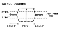
- FIG. 3A is an explanatory diagram for explaining the communication operation of the low-speed transceiver
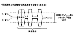
- FIG. 3B is an explanatory diagram for explaining the communication operation of the high-speed transceiver
- FIG. 3C is an explanatory diagram illustrating a communication operation according to an embodiment of the present disclosure.
- FIG. 4 is an explanatory diagram showing the control operation of the control circuit and the potential change of the transmission line.
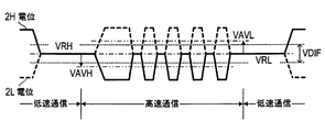
- FIG. 5 is an explanatory diagram showing a differential signal flowing through a transmission line during low-speed communication and high-speed communication.
- FIG. 6 is a block diagram illustrating a configuration of the second node according to the first modification of the present disclosure.
- FIG. 7 is a block diagram illustrating a configuration of the second node according to the second modification of the present disclosure.
- FIG. 8 is a block diagram illustrating a configuration of the second node according to the third modification of the present disclosure.
- the communication system of the present embodiment is for constructing an in-vehicle network that connects various in-vehicle devices such as an ECU for vehicle control so that communication is possible. As shown in FIG. And a plurality of nodes 10 connected in a bus form.
- the transmission path 2 includes a pair of positive and negative communication lines 2H and 2L, and transmits a differential signal transmitted from each node 10 via the communication lines 2H and 2L.
- the plurality of nodes 10 are for performing differential communication with other nodes 10 via the transmission path 2, and are provided in various in-vehicle devices constituting the in-vehicle network.
- this node 10 there are two types of nodes: a first node 10a for low speed communication and a second node 10b capable of performing both low speed communication and high speed communication.
- the first node 10a for low-speed communication includes a low-speed transceiver (LOW SPEED TR) 12 for constructing CAN or CAN-FD via the transmission line 2, and another node 10 (10a, 10a, 10b) and a control circuit 16 that performs differential communication (low-speed communication).
- LOW SPEED TR low-speed transceiver
- the second node 10b for high-speed communication includes the same low-speed transceiver 12 as the first node 10a, a high-speed transceiver (HIGH SPEED TR) 14 for performing differential communication (high-speed communication) faster than the low-speed transceiver 12, and a control And a circuit 18.
- a high-speed transceiver HGH SPEED TR
- differential communication high-speed communication
- the control circuit 18 is constituted by, for example, a microcomputer for communication control, and is for performing data transmission / reception (high-speed communication or low-speed communication) using the low-speed transceiver 12 and the high-speed transceiver 14.
- the control circuit 18 functions as a control unit.
- the control circuit 18 switches the low-speed transceiver 12 of the other node 10 (10a or 10b) to the sleep mode and starts high-speed communication (transmission). This operation will be described in detail later.
- the low-speed transceiver 12 includes a driver TXL1 and a receiver RXL1 for differential communication (low-speed communication), similar to the well-known CAN or CAN-FD transceiver.
- the high-speed transceiver 14 is also composed of a driver TXH1 for differential communication (high-speed communication) and a receiver RXH1.
- the driver TXH1 and the receiver RXH1 of the high-speed transceiver 14 are connected to the two communication lines 2H and 2L with a polarity opposite to that of the driver TXL1 and the receiver RXL1 of the low-speed transceiver 12.
- the low-speed transceiver 12 determines that the transmission path 2 is dominant. If the potential difference is less than or equal to the recessive threshold VDIF, the transmission path 2 is determined to be recessive.
- the low-speed transceiver 12 can switch the operation mode from the normal mode in which data can be transmitted / received to the sleep mode (in other words, the low power mode) in which the data transmission / reception is stopped. In the sleep mode, the output of the low-speed transceiver 12 is high impedance.
- the low-speed transceiver 12 When the low-speed transceiver 12 is in the sleep mode, when the potential difference between the communication lines 2H and 2L exceeds the recessive threshold VDIF due to a wake-up command or the like transmitted from another node 10, the low-speed transceiver 12 returns to the normal mode.
- the low-speed transceiver 12 when the low-speed transceiver 12 is in the sleep mode and the potential difference between the communication lines 2H and 2L does not exceed the recessive threshold VDIF, the low-speed transceiver 12 maintains the sleep mode and stops the communication operation.
- the low-speed transceiver 12 is set to the sleep mode and the potential difference between the communication lines 2H and 2L is suppressed to the recessive threshold VDIF or less. You can do it.
- the high-speed transceiver 14 is connected to the transmission path 2 with the opposite polarity to that of the low-speed transceiver 12, and during high-speed communication by the high-speed transceiver 14, the potentials of the communication lines 2H and 2L are as shown in FIG.
- the polarity is opposite to that during low-speed communication.
- the differential signal output from the high-speed transceiver 14 does not cause the potential difference between the communication lines 2H and 2L to exceed the recessive threshold VDIF of the low-speed transceiver 12.
- the minimum value of the potential difference between the communication lines 2H and 2L during high-speed communication is a negative voltage value having a polarity different from that of the recessive threshold VDIF.
- the low-speed transceiver 12 can be prevented from starting low-speed communication, and high-speed communication can be performed with a differential signal having an amplitude larger than the recessive threshold VDIF during low-speed communication. .
- the output becomes high impedance and does not affect the low-speed communication by the low-speed transceiver 12.
- the control circuit 18 stops the communication operation of its own low-speed transceiver 12 so that its output becomes high impedance, and the high-speed transceiver 14 Communication is started (S2).
- the control circuit 18 stops the communication operation of the high-speed transceiver 14, The output is set to high impedance, and the process proceeds to S3.
- control circuit 18 of the other second node 10b serving as the high-speed communication slave also stops the communication operation of the high-speed transceiver 14 and sets its output to high impedance.
- the control circuit 18 of the second node 10b transmits the sleep mode command from the low-speed transceiver 12 to set the low-speed transceiver 12 of the other node 10 to the sleep mode. After shifting, start high-speed communication.
- the low-speed transceiver 12 of the other node 10 returns to the normal mode during the high-speed communication by the high-speed transceiver 14, and the low-speed transceiver 14 Communication is not started.
- control circuit 18 of the second node 10b serving as the high-speed communication master and the high-speed communication slave can stably implement the high-speed communication without being affected by the low-speed communication via the high-speed transceiver 14.
- the communication system of the present embodiment includes a plurality of second nodes having a high-speed transceiver 14 in an existing transmission line 2 to which a first node 10a having a CAN and CAN-FD low-speed transceiver 12 is bus-connected.
- 10b can be easily constructed by bus connection.
- the communication system of this embodiment is different in communication speed, but it is only necessary to connect the high-speed transceiver 14 having the same configuration as that of the low-speed transceiver 12 to the transmission line 2 with a polarity opposite to that of the low-speed transceiver 12. Realized at low cost.
- the first communication unit at the time of high-speed communication by the second communication unit, not only the first communication unit of the other node is set to the sleep mode, but also the potential difference between the pair of communication lines configuring the transmission path is It is limited to the recessive threshold or less of the first communication unit. For this reason, at the time of high-speed communication by the second communication unit, the first communication unit does not return from the sleep mode to the normal mode and start low-speed communication.
- the amplitude of the differential signal during high-speed communication is The first communication unit is not limited to a recessive threshold or less.
- the node having the second communication unit does not perform high-speed communication using the second communication unit, all the first communication units that are switched to the sleep mode during the high-speed communication are set to the normal mode. Since it returns, it can implement normally also about the low-speed communication by a 1st communication part.
- the communication system of the present disclosure even if the first communication unit for low-speed communication and the second communication unit for high-speed communication are connected by a bus to a common transmission line, the signal is separated into each communication unit. Thus, low-speed communication and high-speed communication can be normally performed without providing a complicated circuit.
- low-speed differential communication such as CAN or CAN-FD and high-speed differential communication with improved noise resistance can be mixed on the same transmission path.
- a communication system can be realized at low cost.
- this indication is not limited to the above-mentioned embodiment, and can take various modes within the range which does not deviate from the gist of this indication.
- the high-speed transceiver 14 is connected to the communication lines 2H and 2L configuring the transmission path 2 with the opposite polarity to the low-speed transceiver 12, but the communication system according to the present disclosure is realized. Need not be configured in this way.
- V2H ⁇ V2L ⁇ VDIF (1) VRH> VAVH (2) VRL ⁇ VAVL (3)
- V2H is the potential of the communication line 2H on the positive side during low speed communication
- V2L is the potential of the communication line 2L on the negative side during low speed communication.
- the equation (1) represents that the potential difference (V2H ⁇ V2L) between the communication lines 2H and 2L is set to be equal to or less than the recessive threshold VDIF in the low-speed communication during the high-speed communication.
- VRH in the equation (2) is a recessive potential of the communication line 2H at the time of low-speed communication
- VAVH is an average of the maximum value and the minimum value of the amplitude of the communication line 2H at the time of high-speed communication. Represents a potential.
- VRL in equation (3) represents the recessive potential of the communication line 2L during low-speed communication
- VAVL represents the average potential of the maximum and minimum values of the amplitude of the communication line 2L during high-speed communication.
- the second node 10b is designed using the expressions (1) to (3) as the execution conditions for high-speed communication, the high-speed communication can be performed while preventing the potential difference between the communication lines 2H and 2L from exceeding the recessive threshold VDIF for low-speed communication.
- the amplitude of the differential signal can be made larger than the recessive threshold VDIF.
- the bias circuit 20 of Modification 1 shown in FIG. 6 is configured by an output circuit that outputs a current so that the potentials of the communication lines 2H and 2L have a potential difference of opposite polarity to that during low-speed communication.
- the output terminal on the side is connected to the communication line 2H, and the output terminal on the positive electrode side is connected to the communication line 2L.
- the bias circuit 20 outputs a current to the communication lines 2H and 2L so that the potential of the communication line 2H becomes VAWH and the potential of the communication line 2L becomes VAVL. Note that when a voltage is output to the communication lines 2H and 2L, a resistor having an output impedance equivalent to that at the time of current output may be used.
- the transmission / reception terminal of the high-speed transceiver 14 is a filter element that blocks the DC signal component and allows the communication high-frequency signal component to pass through the transmission line 2 (communication lines 2H and 2L). AC coupling is performed via capacitors C1 and C2 in the figure.
- control circuit 18 normally stops the operation of the bias circuit 20, makes its output high impedance, and only performs the bias circuit 20 when performing high-speed communication using the high-speed transceiver 14 as a high-speed communication master. Make it work.
- the bias circuit 20 of the second modification shown in FIG. 7 is configured by a low-speed transceiver configured by a driver TXL2 for differential communication (low-speed communication) and a receiver RXL2.
- the low-speed transceiver constituting the bias circuit 20 is connected to the communication lines 2H and 2L with the opposite polarity to the low-speed transceiver 12 for low-speed communication.
- the transmission / reception terminal of the high-speed transceiver 14 is AC-coupled to the transmission path 2 (communication lines 2H and 2L), and the control circuit 18 passes through the driver TXL2 during high-speed communication.
- a bias voltage is applied to the communication lines 2H and 2L.
- the energization direction of the bias current between the positive and negative output terminals of the driver TXL2 and the communication line is the forward direction.
- the diodes D1 and D2 are provided.
- diodes D1 and D2 are used to adjust a potential difference (in other words, a bias voltage) between the communication lines 2H and 2L by a voltage drop (about 0.7 V in this case) generated when energized.
- the driver driver TXL2 can generate a potential difference with a polarity opposite to that during low-speed communication between the communication lines 2H and 2L.
- the potential difference may not be a potential difference suitable for high-speed communication.
- the potential difference between the communication lines 2H and 2L can be adjusted using the diodes D1 and D2.
- the bias voltage applied between the communication lines 2H and 2L at the time of high-speed communication can be adjusted to a more appropriate voltage compared to the second modification.
- High-speed communication can be implemented more optimally.
- the voltage is adjusted by using the forward voltage drop of the diodes D1 and D2.
- a resistor may be used, and a combination of the diode and the resistor is used. May be used.
- a receiver RXL2 is provided.
- the receiver RXL2 is not particularly necessary. It may be deleted.
- the high-speed transceiver 14 is AC-coupled to the communication lines 2H and 2L.
- the connection of the transmission / reception terminal may be of the opposite polarity to the figure (in other words, the same polarity as the low-speed transceiver 12).
Landscapes
- Engineering & Computer Science (AREA)
- Computer Networks & Wireless Communication (AREA)
- Signal Processing (AREA)
- Power Engineering (AREA)
- Dc Digital Transmission (AREA)
Abstract
伝送路(2)にバス型接続されるノードの一部は、低速通信用の第1通信部12に加えて、高速通信用の第2通信部(14)と制御部(18)とを備える。制御部は、高速通信開始時に、第1通信部からスリープ指令を送信させて他のノードの第1通信部をスリープモードへ移行させ、高速通信が完了すると、第1通信部からウエイクアップ指令を送信させて他のノードの第1通信部をノーマルモードへ移行させる。第2通信部は、伝送路の電位差の最大値が第1通信部のレセッシブ閾値以下となり、電位差の最小値がレセッシブ閾値とは極性が異なる負の電圧値となる差動信号にて、高速通信を実施する。
Description
本出願は、2015年7月17日に出願された日本特許出願番号2015-142928号に基づくもので、ここにその記載内容を援用する。
本開示は、共通の伝送路にバス接続された複数のノード間で差動通信を行うための通信システムに関する。
自動車に搭載されて差動通信を行う通信システム(車載ネットワーク)として、通信速度が最大1Mbps程度のCAN(Controller Area Network、登録商標)が知られている。
また、通信速度が最大8Mbps程度となって、CANよりも高速通信が可能なCAN-FD(CAN with Flexible Data-Rate、登録商標)も知られている。
CAN-FDは、フレーム構成のうち、データ及びCRC(Cyclic Redundancy Check)の領域)を高速化し、他の領域はCANと同一にすることで、CANと共通の伝送路を利用して、CANよりも高速の差動通信ができるようにしたものである。
ところで、自動車においては、搭載される電子制御装置(ECU:Electronic Control Unit)の増加に伴い、車載ネットワークの更なる高速化が求められている。
高速通信が可能な通信方式としては、イーサネット(Ethernet:登録商標)が一般的であることから、高速化の要求に応えるために、車載ネットワークにも、例えば、通信速度が100Mbps程度のイーサネットを採用することが考えられる。
しかし、イーサネットは、CANやCAN-FDとは物理層の特性やプロトコルが異なることから、CANやCAN-FDのネットワークが構築された自動車において、別途高速通信用のイーサネットを構築するには、専用の通信線を配線しなければならない。
一方、一対の通信線からなる伝送路を使って、第1の信号(音声データ)を同相信号、第1の信号に同期したクロック信号を差動信号、として送信する通信技術が提案されている(例えば、特許文献1参照)。
上記特許文献1に提案の技術は、音声データとその音声データに同期したクロック信号を共通の伝送路を使って多重伝送することで、受信側でアナログ音声信号を精度良く復元できるようにする多重通信技術である。
そして、こうした多重通信技術を車載ネットワークに適用することにより、CANやCAN-FDのネットワークが構築された自動車において、このネットワークと共通の伝送路を使って高速通信を実施することも考えられる。
例えば、CANやCAN-FD等の差動通信用の一対の通信線に、高速通信用の同相信号を重畳することで、共通の伝送路を使って、CANやCAN-FD等の既存の差動通信と同相信号を用いた高速通信とを実施できるようにするのである。
しかしながら、上記特許文献1に提案の通信技術は、差動信号と同相信号という2種類の信号を多重伝送する技術であることから、ネットワークに接続される全ての通信端末に、これら各信号を分離して復元し得る受信部を設ける必要があり、通信端末の構成が複雑になる。
また、この場合、通信端末が伝送路を介して一対一で接続されているときには通信端末間で多重通信を行うことができるが、CAN、CAN-FDのように通信端末が伝送路にバス型接続されるシステムでは、良好な通信ができなくなる。
つまり、バス型の通信システムにおいて、通信速度の異なる多重通信を行うには、CAN、CAN-FDのような既存の低速通信用のトランシーバと、高速通信用のトランシーバとが、伝送路にそれぞれ複数接続されることになる。
従って、例えば高速通信用のトランシーバが高速通信を開始し、伝送路の電位が変化したときに、CAN、CAN-FD等の低速通信用のトランシーバが信号を受信したと誤判断して低速通信を開始してしまい、各トランシーバが正常な通信を実施できなくなるのである。
本開示は、上記点に鑑みなされたものであり、共通の伝送路に低速通信用及び高速通信用のトランシーバをバス型接続した際、各トランシーバに信号分離用の回路を設けることなく、低速通信及び高速通信を正常に実施できる通信システムを提供することを目的とする。
本開示の一態様による通信システムは、差動伝送可能な正負一対の通信線を有する伝送路と、伝送路にバス型接続された複数のノードとを備える。そして、複数のノードには、それぞれ、伝送路を介して差動通信を行うための第1通信部が設けられている。
また、複数のノードの少なくとも一部には、第1通信部に加えて、第1通信部よりも高速で差動通信を行うための第2通信部と、第1通信部及び第2通信部の何れかを利用して他のノードとの間で通信を行う制御部とが備えられている。
そして、制御部は、第2通信部を介して他のノードとの間で高速通信を行う際には、第1通信部からスリープ指令を送信させることで、他のノードに設けられた第1通信部をスリープモードへ移行させた後、第2通信部による高速通信を開始する。
スリープモードは、伝送路を構成する一対の通信線の電位差がレセッシブ閾値を超えてドミナントとなるまで動作を停止するモードである。このため、第1通信部がスリープモードに入ると、一対の通信線の電位差がレセッシブ閾値を超えるまで、第1通信部が通信を開始することはない。
また、制御部は、第2通信部を利用した高速通信が完了すると、第1通信部からウエイクアップ指令を送信させることで、他のノードに設けられた第1通信部を、スリープモードから通信を実行可能なノーマルモードへ移行させる。
一方、第2通信部は、一対の通信線の電位差の最大値が第1通信部のレセッシブ閾値以下となり、その電位差の最小値が第1通信部のレセッシブ閾値とは極性が異なる負の電圧値となる差動信号にて、高速通信を実施する。
上記通信システムによれば、共通の伝送路に低速通信用及び高速通信用のトランシーバをバス型接続した際、各トランシーバに信号分離用の回路を設けることなく、低速通信及び高速通信を正常に実施することができる。
本開示についての上記目的およびその他の目的、特徴や利点は、添付の図面を参照しながら下記の詳細な記述により、より明確になる。その図面は、
図1は、本開示の一実施形態の通信システム全体の構成を表すブロック図であり、
図2は、高速通信可能な第2ノードの構成を表すブロック図であり、
図3Aは、低速トランシーバの通信動作を説明する説明図であり、
図3Bは、高速トランシーバの通信動作を説明する説明図であり、
図3Cは、本開示の一実施形態による通信動作を説明する説明図であり、
図4は、制御回路の制御動作及び伝送路の電位変化を表す説明図であり、
図5は、低速通信時及び高速通信時に伝送路を流れる差動信号を表す説明図であり、
図6は、本開示の変形例1の第2ノードの構成を表すブロック図であり、
図7は、本開示の変形例2の第2ノードの構成を表すブロック図であり、
図8は、本開示の変形例3の第2ノードの構成を表すブロック図である。
以下に、本開示の実施形態を図面と共に説明する。
なお、本開示は、下記の実施形態によって何ら限定して解釈されない。また、下記の実施形態の構成の一部を、課題を解決できる限りにおいて省略した態様も本開示の実施形態である。また、請求の範囲に記載した文言のみによって特定される開示の本質を逸脱しない限度において考え得るあらゆる態様も本開示の実施形態である。また、下記の実施形態の説明で用いる符号を請求の範囲にも適宜使用しているが、これは本開示の理解を容易にする目的で使用しており、本開示の技術的範囲を限定する意図ではない。
本実施形態の通信システムは、車両制御用のECU等、各種車載機器を通信可能に接続する車載ネットワークを構築するためのものであり、図1に示すように、伝送路2と、伝送路2にバス型接続された複数のノード10とを備える。
伝送路2は、正負一対の通信線2H、2Lを備え、この通信線2H、2Lを介して、各ノード10から送信された差動信号を伝送する。
また、複数のノード10は、伝送路2を介して他のノード10との間で差動通信を行うためのものであり、車載ネットワークを構成する各種車載機器にそれぞれ設けられている。
このノード10には、低速通信用の第1ノード10aと、低速通信と高速通信との両方を実施可能な第2ノード10bとの2種類のノードが存在する。
低速通信用の第1ノード10aは、伝送路2を介してCAN若しくはCAN-FDを構築するための低速トランシーバ(LOW SPEED TR)12と、この低速トランシーバ12を介して他のノード10(10a、10b)との間で差動通信(低速通信)を行う制御回路16とを備える。
高速通信用の第2ノード10bは、第1ノード10aと同じ低速トランシーバ12と、低速トランシーバ12よりも高速な差動通信(高速通信)を行うための高速トランシーバ(HIGH SPEED TR)14と、制御回路18と、を備える。
制御回路18は、例えば、通信制御用のマイクロコンピュータにて構成されており、低速トランシーバ12及び高速トランシーバ14を利用したデータの送受信(高速通信又は低速通信)を行うためのものである。制御回路18は、制御部として機能する。
そして、制御回路18は、高速トランシーバ14によるデータ送信を開始する際には、他のノード10(10a又は10b)の低速トランシーバ12をスリープモードに切り換え、高速通信(送信)を開始する。なお、この動作については、後で詳しく説明する。
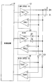
図2に示すように、低速トランシーバ12は、周知のCAN若しくはCAN-FD用のトランシーバと同様、差動通信(低速通信)用のドライバTXL1とレシーバRXL1とにより構成されている。
また高速トランシーバ14も、差動通信(高速通信)用のドライバTXH1とレシーバRXH1とにより構成されている。
そして、この高速トランシーバ14のドライバTXH1及びレシーバRXH1は、低速トランシーバ12のドライバTXL1及びレシーバRXL1とは逆極性で、2本の通信線2H、2Lに接続されている。
これは、高速トランシーバ14による高速通信時に、低速トランシーバ12が通信線2H、2Lの電位差の変化によって低速通信を誤検出して、通信動作を開始するのを防止するためである。
以下、この点について説明する。
まず、図3Aに示すように、低速トランシーバ12は、通信線2Hの電位が通信線2Lの電位よりも高く、その電位差がレセッシブ閾値VDIFを超えると、伝送路2はドミナントであると判定する。また、その電位差がレセッシブ閾値VDIF以下であると、伝送路2はレセッシブであると判定する。
また、低速トランシーバ12は、動作モードを、データの送受信が可能なノーマルモードから、データの送受信を停止するスリープモード(換言すればローパワーモード)へ切り換え可能である。なお、スリープモードでは、低速トランシーバ12の出力はハイインピーダンスとなる。
そして、低速トランシーバ12は、スリープモードであるとき、他のノード10から送信されるウェイクアップコマンド等によって、通信線2H、2Lの電位差がレセッシブ閾値VDIFを超えると、ノーマルモードに復帰する。
換言すれば、低速トランシーバ12は、スリープモードであるとき、通信線2H、2Lの電位差がレセッシブ閾値VDIFを超えなければ、スリープモードを保持し、通信動作を停止する。
このため、高速トランシーバ14による高速通信を、低速トランシーバ12による通信の影響を受けることなく実施するには、低速トランシーバ12をスリープモードにし、通信線2H、2Lの電位差をレセッシブ閾値VDIF以下に抑えるようにすればよい。
一方、このように、通信線2H、2Lの電位差をレセッシブ閾値VDIF以下に抑えて高速通信を行う方法としては、図3Bに示すように、高速トランシーバ14から出力される差動信号の振幅を、レセッシブ閾値VDIF以下に制限することが考えられる。
しかし、高速通信時の差動信号の振幅をレセッシブ閾値VDIF以下に制限すると、高速通信のノイズ耐性が低下するため、高速通信を安定して実施することができなくなる。
そこで、本実施形態では、高速トランシーバ14を、低速トランシーバ12とは逆極性で伝送路2に接続し、高速トランシーバ14による高速通信時には、図3Cに示すように、通信線2H、2Lの電位が低速通信時とは逆極性となるようにしているのである。
従って、高速トランシーバ14による高速通信時に、高速トランシーバ14から出力される差動信号によって、通信線2H、2Lの電位差が低速トランシーバ12のレセッシブ閾値VDIFを超えるようなことはない。
また、レセッシブ閾値VDIFを正電圧としたとき、高速通信時の通信線2H、2Lの電位差の最小値は、レセッシブ閾値VDIFとは極性が異なる負の電圧値となる。
よって、高速トランシーバ14による高速通信時には、低速トランシーバ12が低速通信を開始するのを防止しつつ、低速通信時のレセッシブ閾値VDIFよりも振幅が大きい差動信号にて、高速通信を実施できることになる。
なお、高速トランシーバ14は、高速通信を実施していないとき(通信動作停止時)には、出力がハイインピーダンスとなり、低速トランシーバ12による低速通信に影響を与えることはない。
そこで、本実施形態では、制御回路18を、図4に示す手順で低速通信と高速通信との切り換えを行うように構成することで、共通の伝送路2を使って、低速通信及び高速通信を、互いに影響を与えることなく正常に実施できるようにしている。
すなわち、制御回路18は、自身のノード(第2ノード10b)を高速通信マスターとして、高速トランシーバ14による高速通信を開始させる際には、まずS1(Sは手順を表す)にて、低速トランシーバ12からスリープモードコマンドを送信させる。
なお、このように低速トランシーバ12を介して低速通信を実施する際、制御回路18は、高速トランシーバ14の出力をハイインピーダンスにする。
すると、伝送路2に接続された他のノード10(10a、10b)の低速トランシーバ12にスリープモードコマンドが伝送されて、全ての低速トランシーバ12の動作モードが、ノーマルモードからスリープモードへ切り替わる。
このように、他のノード10の低速トランシーバ12をスリープモードに切り替えると、制御回路18は、自身の低速トランシーバ12の通信動作を停止させることで、その出力をハイインピーダンスにし、高速トランシーバ14による高速通信を開始する(S2)。
そして、この高速通信により、高速通信スレーブとなる他の第2ノード10bの高速トランシーバ14との間でのデータの送受信が完了すると、制御回路18は、高速トランシーバ14の通信動作を停止させ、その出力をハイインピーダンスにし、S3に移行する。
なお、高速通信が完了した際には、高速通信スレーブとなる他の第2ノード10bの制御回路18も、高速トランシーバ14の通信動作を停止させ、その出力をハイインピーダンスにする。
次に、S3では、制御回路18は、低速トランシーバ12からウェイクアップコマンドを送信させる。この結果、伝送路2に接続された他のノード10(10a、10b)の低速トランシーバ12が全てスリープモードからノーマルモードへ切り替えられ、伝送路2に接続された全ての低速トランシーバ12が、通常の低速通信を実施できるようになる(S4)。
このように、第2ノード10bの制御回路18は、高速通信マスターとして高速通信を開始する際には、低速トランシーバ12からスリープモードコマンドを送信させて他のノード10の低速トランシーバ12をスリープモードに移行させた後、高速通信を開始する。
そして、高速トランシーバ14は、低速トランシーバ12とは逆極性で伝送路2に接続されているので、高速トランシーバ14による高速通信時に、他のノード10の低速トランシーバ12がノーマルモードに復帰して、低速通信を開始することはない。
従って、高速通信マスター及び高速通信スレーブとなる第2ノード10bの制御回路18は、高速トランシーバ14を介して、低速通信の影響を受けることなく、高速通信を安定して実施することができる。
よって、本実施形態の通信システムによれば、差動通信用の伝送路2に接続された低速トランシーバ12と高速トランシーバ14とを利用して、低速通信及び高速通信をそれぞれ正常に実施することができるようになる。
また、本実施形態の通信システムは、CAN、CAN-FD用の低速トランシーバ12を備えた第1ノード10aがバス接続された既存の伝送路2に、高速トランシーバ14を備えた複数の第2ノード10bをバス接続することより、容易に構築することができる。
特に、本実施形態の通信システムは、通信速度は異なるものの、低速トランシーバ12と同様の構成を有する高速トランシーバ14を、低速トランシーバ12とは逆極性で伝送路2に接続するだけでよいので、極めて低コストで実現できる。
本開示の通信システムによれば、第2通信部による高速通信時には、他のノードの第1通信部がスリープモードに設定されるだけでなく、伝送路を構成する一対の通信線の電位差が、第1通信部のレセッシブ閾値以下に制限される。このため、第2通信部による高速通信時に、第1通信部がスリープモードからノーマルモードに復帰して、低速通信を開始することはない。
また、第2通信部が高速通信に使用する差動信号の最小値は、第1通信部のレセッシブ閾値とは極性が異なる負の電圧になることから、高速通信時の差動信号の振幅が、第1通信部のレセッシブ閾値以下に制限されることはない。
このため、高速通信時に、差動信号の振幅が制限されることによって、高速通信のノイズ耐性が低下するようなことはなく、高速通信を精度良く実施することができる。
また、第2通信部を備えたノードが、第2通信部を使って高速通信を行うことがない場合には、高速通信時にスリープモードに切り替えられた全ての第1通信部が、ノーマルモードに戻るので、第1通信部による低速通信についても、正常に実施することができる。
よって、本開示の通信システムによれば、低速通信用の第1通信部と高速通信用の第2通信部とを共通の伝送路にバス型接続しても、各通信部に、信号を分離するための複雑な回路を設けることなく、低速通信及び高速通信を正常に実施できるようになる。
このため、本開示によれば、CANやCAN-FDの低速な差動通信と、ノイズ耐性を向上した高速な差動通信とを、同一の伝送路上で混在させることができ、しかも、そのための通信システムを低コストで実現することが可能となる。
以上、本開示の一実施形態について説明したが、本開示は上記実施形態に限定されるものではなく、本開示の要旨を逸脱しない範囲内にて種々の態様をとることができる。
例えば、上記実施形態では、伝送路2を構成する通信線2H、2Lに対し、高速トランシーバ14を低速トランシーバ12とは逆極性で接続するものとして説明したが、本開示の通信システムを実現するには、必ずしもこのように構成する必要はない。
つまり、本開示における高速通信の実行条件は、次式(1)~(3)で表すことができる。
V2H-V2L < VDIF …(1)
VRH > VAVH …(2)
VRL < VAVL …(3)
但し、(1)式において、V2Hは、低速通信時に正極側となる通信線2Hの電位、V2Lは、低速通信時に負極側となる通信線2Lの電位である。そして、(1)式は、高速通信時には、通信線2H、2Lの電位差(V2H-V2L)を、低速通信時のレセッシブ閾値VDIF以下にすることを表している。
VRH > VAVH …(2)
VRL < VAVL …(3)
但し、(1)式において、V2Hは、低速通信時に正極側となる通信線2Hの電位、V2Lは、低速通信時に負極側となる通信線2Lの電位である。そして、(1)式は、高速通信時には、通信線2H、2Lの電位差(V2H-V2L)を、低速通信時のレセッシブ閾値VDIF以下にすることを表している。
また、図5に示すように、(2)式におけるVRHは、低速通信時における通信線2Hのレセッシブ電位、同じくVAVHは、高速通信時における通信線2Hの振幅の最大値と最小値との平均電位を表している。
同様に、(3)式におけるVRLは、低速通信時における通信線2Lのレセッシブ電位、VAVLは、高速通信時における通信線2Lの振幅の最大値と最小値の平均電位を表している。
従って、式(1)~(3)を高速通信の実行条件として第2ノード10bを設計すれば、通信線2H、2Lの電位差が低速通信のレセッシブ閾値VDIFを超えるのを防止しつつ、高速通信の差動信号の振幅をレセッシブ閾値VDIFよりも大きくすることができる。
このため、図6~図8に示す変形例1~3のように、第2ノード10bには、通信線2H、2L間にレセッシブ閾値VDIFとは極性が異なるバイアス電圧を印加するためのバイアス回路(BIAS)20を設けるようにしてもよい。
ここで、図6に示す変形例1のバイアス回路20は、通信線2H、2Lの電位が低速通信時とは逆極性の電位差となるよう電流を出力する出力回路にて構成されており、負極側の出力端が通信線2Hに接続され、正極側の出力端が通信線2Lに接続されている。
そして、このバイアス回路20は、通信線2Hの電位がVAVHとなり、通信線2Lの電位がVAVLとなるよう、通信線2H、2Lに電流を出力する。なお、通信線2H、2Lに電圧を出力する際には、電流出力時と等価な出力インピーダンスを持つ抵抗を利用すればよい。
また、図6に示す第2ノード10bにおいて、高速トランシーバ14の送受信端子は、伝送路2(通信線2H、2L)に対し、直流信号成分を遮断し通信用の高周波信号成分を通過させるフィルタ素子(図ではコンデンサC1、C2)を介してAC結合されている。
そして、制御回路18は、通常は、バイアス回路20の動作を停止させて、その出力をハイインピーダンスにし、高速通信マスターとして高速トランシーバ14を利用した高速通信を実施するときにだけ、バイアス回路20を動作させる。
従って、図6に示す変形例1の第2ノード10bを利用して、車載ネットワークを構築しても、上記実施形態と同様の効果を得ることができる。
次に、図7に示す変形例2のバイアス回路20は、低速トランシーバ12と同様、差動通信(低速通信)用のドライバTXL2とレシーバRXL2とにより構成された低速トランシーバにて構成されている。そして、バイアス回路20を構成する低速トランシーバは、低速通信用の低速トランシーバ12とは逆極性で、通信線2H、2Lに接続されている。
また、図7に示す第2ノード10bにおいて、高速トランシーバ14の送受信端子は、伝送路2(通信線2H、2L)にAC結合されており、制御回路18は、高速通信時に、ドライバTXL2を介して、通信線2H、2Lにバイアス電圧を印加させる。
従って、図7に示す変形例2の第2ノード10bによれば、変形例1と同様の効果を得ることができるだけでなく、バイアス回路20として、低速トランシーバを利用できるので、変形例1に比べて、バイアス回路20をより低コストで実現できることになる。
次に、図8に示す変形例3のバイアス回路20は、図7に示したバイアス回路20において、ドライバTXL2の正負の出力端と通信線との間に、バイアス電流の通電方向を順方向とするダイオードD1、D2を設けることにより構成されている。
このダイオードD1、D2は、通電時に生じる電圧降下(この場合、約0.7V)により、通信線2H、2Lの電位差(換言すればバイアス電圧)を調整するのに用いられている。
つまり、バイアス回路20に差動通信用のトランシーバを利用した場合、そのトランシーバのドライバTXL2では、通信線2H、2L間に低速通信時とは逆極性の電位差を発生させることはできても、その電位差が高速通信に適した電位差にできないことがある。
そこで、図8に示す変形例3では、ダイオードD1、D2を利用して、通信線2H、2Lの電位差を調整できるようにしているのである。
このため、図8に示す変形例3の第2ノード10bによれば、変形例2に比べ、高速通信時に通信線2H、2L間に印加するバイアス電圧をより適正な電圧に調整できるようになり、高速通信をより最適に実施できるようになる。
なお、図8では、ダイオードD1、D2の順方向電圧降下を利用して、電圧調整しているが、このための電圧調整素子としては、抵抗を利用しても良く、ダイオードと抵抗を組み合わせて利用してもよい。
また、図7、図8に示す変形例2、3のバイアス回路20は、低速トランシーバを用いて構成されているため、レシーバRXL2が設けられているが、このレシーバRXL2は特に必要はないため、削除してもよい。
また、図6~図8に示す変形例1~3のようにバイアス回路20を設けた場合、高速トランシーバ14は、各通信線2H、2LにAC結合されることから、各通信線2H、2Lへの送受信端子の接続は、図とは逆極性(換言すれば低速トランシーバ12と同極性)にしてもよい。
Claims (5)
- 差動伝送可能な正負一対の通信線(2H、2L)を有する伝送路(2)と、
前記伝送路にバス型接続され、前記伝送路を介して差動通信を行うための第1通信部(12)を有する複数のノード(10)と、
を備え、
前記複数のノードの少なくとも一部(10b)は、前記第1通信部に加えて、
前記第1通信部よりも高速で差動通信を行うための第2通信部(14)と、
前記第1通信部及び前記第2通信部の何れかを利用して他のノードとの間で通信を行う制御部(18)と、
を備え、
前記制御部は、
前記第2通信部を介して他のノードとの間で高速通信を行う際には、前記第1通信部からスリープ指令を送信させることで、他のノードに設けられた前記第1通信部を、前記一対の通信線の電位差がレセッシブ閾値を超えてドミナントとなるまで動作を停止するスリープモードへ移行させた後、前記第2通信部による高速通信を開始し、該高速通信が完了すると、前記第1通信部からウエイクアップ指令を送信させることで、他のノードに設けられた前記第1通信部を、前記スリープモードから前記差動通信を実行可能なノーマルモードへ移行させるように構成されており、
前記第2通信部は、前記一対の通信線の電位差の最大値が前記第1通信部のレセッシブ閾値以下となり、該電位差の最小値が前記第1通信部のレセッシブ閾値とは極性が異なる負の電圧値となる差動信号にて前記高速通信を実施するよう構成されている、通信システム。 - 前記第2通信部を構成する高速トランシーバは、通信用の送受信端子が、前記第1通信部を構成する低速トランシーバの送受信端子とは逆極性で、前記伝送路の2本の通信線に接続されている、請求項1に記載の通信システム。
- 前記第1通信部、前記第2通信部、及び前記制御部を備えたノードには、更に、前記一対の通信線に対し、前記第1通信部のレセッシブ閾値とは極性が異なるバイアス電圧を印加するバイアス回路(20)、が備えられ、
前記第2通信部を構成する高速トランシーバは、通信用の送受信端子が、前記一対の通信線に、直流信号成分を遮断し通信用の高周波信号成分を通過させるフィルタ素子(C1、C2)を介して接続され、
前記制御部は、前記第2通信部を介して他のノードとの間で高速通信を行う際には、前記バイアス回路を介して、2本の通信線間に前記バイアス電圧を印加するよう構成されている、請求項1に記載の通信システム。 - 前記バイアス回路は、前記第1通信部を構成する低速トランシーバと同一構成のドライバ(TXL2)を備え、該ドライバを、前記第1通信部とは逆極性で前記一対の通信線に接続することにより構成されている、請求項3に記載の通信システム。
- 前記バイアス回路を構成するドライバと前記一対の通信線との間には、前記バイアス電圧を調整するための電圧調整素子(D1、D2)が設けられている、請求項3又は請求項4に記載の通信システム。
Priority Applications (2)
| Application Number | Priority Date | Filing Date | Title |
|---|---|---|---|
| US15/744,103 US10284388B2 (en) | 2015-07-17 | 2016-06-13 | Communication system |
| DE112016003218.8T DE112016003218T5 (de) | 2015-07-17 | 2016-06-13 | Kommunikationssystem |
Applications Claiming Priority (2)
| Application Number | Priority Date | Filing Date | Title |
|---|---|---|---|
| JP2015142928A JP6299692B2 (ja) | 2015-07-17 | 2015-07-17 | 通信システム |
| JP2015-142928 | 2015-07-17 |
Publications (1)
| Publication Number | Publication Date |
|---|---|
| WO2017013829A1 true WO2017013829A1 (ja) | 2017-01-26 |
Family
ID=57834982
Family Applications (1)
| Application Number | Title | Priority Date | Filing Date |
|---|---|---|---|
| PCT/JP2016/002848 Ceased WO2017013829A1 (ja) | 2015-07-17 | 2016-06-13 | 通信システム |
Country Status (4)
| Country | Link |
|---|---|
| US (1) | US10284388B2 (ja) |
| JP (1) | JP6299692B2 (ja) |
| DE (1) | DE112016003218T5 (ja) |
| WO (1) | WO2017013829A1 (ja) |
Families Citing this family (15)
| Publication number | Priority date | Publication date | Assignee | Title |
|---|---|---|---|---|
| JP6801684B2 (ja) * | 2018-03-29 | 2020-12-16 | 株式会社デンソー | 振動型ジャイロスコープ |
| DE102018206067A1 (de) | 2018-04-20 | 2019-10-24 | Robert Bosch Gmbh | Verfahren und Vorrichtung zum Bestimmen einer hochgenauen Position eines Fahrzeugs |
| DE102018218387A1 (de) * | 2018-10-26 | 2020-04-30 | Robert Bosch Gmbh | Teilnehmerstation für ein serielles Bussystem und Verfahren zur Übertragung von Daten mit Manipulationsschutz in einem seriellen Bussystem |
| DE102018221680A1 (de) * | 2018-12-13 | 2020-06-18 | Robert Bosch Gmbh | Einrichtung für eine Teilnehmerstation eines seriellen Bussystems und Verfahren zur Kommunikation in einem seriellen Bussystem |
| DE102018221961A1 (de) * | 2018-12-17 | 2020-06-18 | Robert Bosch Gmbh | Teilnehmerstation für ein serielles Bussystem und Verfahren zur Kommunikation in einem seriellen Bussystem |
| DE102018221957A1 (de) * | 2018-12-17 | 2020-06-18 | Robert Bosch Gmbh | Einrichtung für eine Teilnehmerstation eines seriellen Bussystems und Verfahren zur Kommunikation in einem seriellen Bussystem |
| DE102019204115A1 (de) * | 2019-03-26 | 2020-10-01 | Robert Bosch Gmbh | Teilnehmerstation für ein serielles Bussystem und Verfahren zur Kommunikation in einem seriellen Bussystem |
| DE102019213781A1 (de) * | 2019-09-11 | 2021-03-11 | Robert Bosch Gmbh | Emissionsreduktionsvorrichtung und Verfahren zur Reduktion der Emission einer Sende-/Empfangseinrichtung für ein serielles Bussystem |
| EP3852314B1 (en) | 2020-01-17 | 2024-03-13 | Nxp B.V. | Controller area network transceiver and controller |
| DE102020205257A1 (de) * | 2020-04-24 | 2021-10-28 | Robert Bosch Gesellschaft mit beschränkter Haftung | Kommunikationssteuereinrichtung und Sende-/Empfangseinrichtung für eine Teilnehmerstation eines seriellen Bussystems und Verfahren zur Kommunikation in einem seriellen Bussystem |
| EP3917100B1 (en) * | 2020-05-26 | 2025-04-30 | Nxp B.V. | Controller area network controller and transceiver |
| CN112087359B (zh) * | 2020-09-28 | 2022-03-18 | 北京东土科技股份有限公司 | 一种串行通信系统 |
| EP4099641A1 (en) | 2021-06-03 | 2022-12-07 | Nxp B.V. | Transceiver device |
| EP4099640A1 (en) | 2021-06-03 | 2022-12-07 | Nxp B.V. | Transceiver device |
| US20250119314A1 (en) * | 2023-10-06 | 2025-04-10 | HK Oceancomm Technology Co., Limited | Hybrid Wired Communication System Combining Controller Area Network (CAN) and Other High Speed Communication Technologies |
Citations (2)
| Publication number | Priority date | Publication date | Assignee | Title |
|---|---|---|---|---|
| JP2010206268A (ja) * | 2009-02-27 | 2010-09-16 | Denso Corp | 通信システム、及びノード |
| JP2012028865A (ja) * | 2010-07-20 | 2012-02-09 | Denso Corp | ノード |
Family Cites Families (10)
| Publication number | Priority date | Publication date | Assignee | Title |
|---|---|---|---|---|
| JP3281043B2 (ja) * | 1992-08-06 | 2002-05-13 | マツダ株式会社 | 多重伝送装置 |
| DE10248456A1 (de) * | 2001-10-19 | 2003-06-18 | Denso Corp | Fahrzeugkommunikationssystem |
| JP4952212B2 (ja) * | 2006-11-22 | 2012-06-13 | 株式会社デンソー | 通信妨害防止装置、通信システムのノード、通信システム、車両用故障診断装置、及び車載装置 |
| JP4645717B2 (ja) * | 2008-09-26 | 2011-03-09 | ソニー株式会社 | インタフェース回路および映像装置 |
| US20120051241A1 (en) * | 2010-08-31 | 2012-03-01 | Denso Corporation | Communication system with a plurality of nodes communicably connected for communication based on NRZ (non return to zero) code |
| EP2671335B1 (en) * | 2011-01-31 | 2017-12-06 | Raytheon Company | High and low speed serial interface multiplexing circuit |
| EP2521319B1 (en) * | 2011-05-02 | 2015-10-14 | Robert Bosch GmbH | Controller area network with flexible data-rate |
| US9231789B2 (en) * | 2012-05-04 | 2016-01-05 | Infineon Technologies Ag | Transmitter circuit and method for operating thereof |
| JP5847212B2 (ja) | 2014-01-31 | 2016-01-20 | 東亜工業株式会社 | 熱間プレス装置 |
| JP2015144353A (ja) * | 2014-01-31 | 2015-08-06 | 株式会社デンソー | 通信システム |
-
2015
- 2015-07-17 JP JP2015142928A patent/JP6299692B2/ja not_active Expired - Fee Related
-
2016
- 2016-06-13 US US15/744,103 patent/US10284388B2/en not_active Expired - Fee Related
- 2016-06-13 WO PCT/JP2016/002848 patent/WO2017013829A1/ja not_active Ceased
- 2016-06-13 DE DE112016003218.8T patent/DE112016003218T5/de not_active Withdrawn
Patent Citations (2)
| Publication number | Priority date | Publication date | Assignee | Title |
|---|---|---|---|---|
| JP2010206268A (ja) * | 2009-02-27 | 2010-09-16 | Denso Corp | 通信システム、及びノード |
| JP2012028865A (ja) * | 2010-07-20 | 2012-02-09 | Denso Corp | ノード |
Also Published As
| Publication number | Publication date |
|---|---|
| US20180205572A1 (en) | 2018-07-19 |
| DE112016003218T5 (de) | 2018-04-19 |
| US10284388B2 (en) | 2019-05-07 |
| JP6299692B2 (ja) | 2018-03-28 |
| JP2017028398A (ja) | 2017-02-02 |
Similar Documents
| Publication | Publication Date | Title |
|---|---|---|
| JP6299692B2 (ja) | 通信システム | |
| US9965426B2 (en) | System and method for a low emission network | |
| EP3094044B1 (en) | Method and system with sleep and wake up control over dc path | |
| KR102366501B1 (ko) | 버스 시스템용 가입자국 및 가입자국에 대한 전자기 적합성의 범위 내에서 간섭 저항성을 증대시키기 위한 방법 | |
| US9001843B2 (en) | Fast wake-up and link acquisition in reduced-twisted pair gigabit Ethernet applications | |
| US20150222455A1 (en) | Communication system | |
| JP2851124B2 (ja) | 多重伝送方式 | |
| US11516043B2 (en) | Monolithic high-voltage transceiver connected to two different supply voltage domains | |
| CN111149326B (zh) | 用于总线系统的发送/接收装置和用于减小在不同的位状态之间过渡时的振荡趋势的方法 | |
| CN105191221A (zh) | 双电压通信总线 | |
| JP6496836B2 (ja) | 中継装置、電子制御装置及び車載ネットワークシステム | |
| CN115441889A (zh) | 收发器装置 | |
| US10432188B2 (en) | Ringing suppression circuit and ringing suppression method | |
| US20180253395A9 (en) | Dual voltage communication bus | |
| EP3435607B1 (en) | In-vehicle processing device and in-vehicle system | |
| EP1751924B1 (en) | Circuit arrangement and method of operating such circuit arrangement | |
| CN111164937B (zh) | 用于总线系统的发送/接收装置和用于减小在不同的位状态之间过渡时的振荡趋势的方法 | |
| JP5626240B2 (ja) | ドライバ回路 | |
| US9264042B2 (en) | Serial transmission driving method | |
| US8466712B1 (en) | Direct current (DC) coupling with rail to rail common mode | |
| JP7000707B2 (ja) | 通信装置および通信システム | |
| JP7024487B2 (ja) | バス通信システム | |
| JP2005159728A (ja) | データ伝送方法 |
Legal Events
| Date | Code | Title | Description |
|---|---|---|---|
| 121 | Ep: the epo has been informed by wipo that ep was designated in this application |
Ref document number: 16827398 Country of ref document: EP Kind code of ref document: A1 |
|
| WWE | Wipo information: entry into national phase |
Ref document number: 15744103 Country of ref document: US |
|
| WWE | Wipo information: entry into national phase |
Ref document number: 112016003218 Country of ref document: DE |
|
| 122 | Ep: pct application non-entry in european phase |
Ref document number: 16827398 Country of ref document: EP Kind code of ref document: A1 |