WO2017013824A1 - 頭外定位処理装置、頭外定位処理方法、プログラム - Google Patents
頭外定位処理装置、頭外定位処理方法、プログラム Download PDFInfo
- Publication number
- WO2017013824A1 WO2017013824A1 PCT/JP2016/002564 JP2016002564W WO2017013824A1 WO 2017013824 A1 WO2017013824 A1 WO 2017013824A1 JP 2016002564 W JP2016002564 W JP 2016002564W WO 2017013824 A1 WO2017013824 A1 WO 2017013824A1
- Authority
- WO
- WIPO (PCT)
- Prior art keywords
- filter
- correction
- head localization
- band
- localization processing
- Prior art date
- Legal status (The legal status is an assumption and is not a legal conclusion. Google has not performed a legal analysis and makes no representation as to the accuracy of the status listed.)
- Ceased
Links
Images





Classifications
-
- H—ELECTRICITY
- H04—ELECTRIC COMMUNICATION TECHNIQUE
- H04S—STEREOPHONIC SYSTEMS
- H04S1/00—Two-channel systems
-
- H—ELECTRICITY
- H04—ELECTRIC COMMUNICATION TECHNIQUE
- H04S—STEREOPHONIC SYSTEMS
- H04S5/00—Pseudo-stereo systems, e.g. in which additional channel signals are derived from monophonic signals by means of phase shifting, time delay or reverberation
- H04S5/02—Pseudo-stereo systems, e.g. in which additional channel signals are derived from monophonic signals by means of phase shifting, time delay or reverberation of the pseudo four-channel type, e.g. in which rear channel signals are derived from two-channel stereo signals
Definitions
- the present invention relates to an out-of-head localization processing apparatus, an out-of-head localization processing method, and a program.
- Patent Document 1 describes a listener's head related transfer function HRTF (Head Related Related Transfer Function) as a method for localizing a sound image out of the head.
- HRTF Head Related Related Transfer Function
- a reproduction signal has an inverse characteristic of the head-related transfer function from the virtual sound source to the listener's ears and the ear canal transfer function ECTF (Ear Canal Transfer function). Folded.
- ECTF Ear Canal Transfer function
- the ear canal transfer function ECTF is measured by inserting a measurement microphone into the listener's ear canal or substituting a dummy head.
- JP 2002-209300 A Japanese Patent Laying-Open No. 2015-126268
- the ear canal transfer function ECTF is a transfer function that determines sound peculiar to headphones or earphones.
- the ear canal transfer function ECTF includes a frequency amplitude characteristic related to sound quality and a phase characteristic related to what phase the eardrum is vibrated.
- the out-of-head localization processing convolves the inverse characteristics of the ear canal transfer function ECTF, there may be cases where the sound quality and force peculiar to headphones or earphones cannot be obtained. Therefore, it may not be possible to perform out-of-head localization with a sound quality preferable for the user.
- the change in sound quality becomes large. That is, when the processing sound of the out-of-head localization processing is compared with the sound of the headphones themselves, the sound quality is greatly changed. Therefore, an out-of-head localization process is desired while leaving the sound quality of the headphones.
- Non-Patent Document 1 describes that 2 kHz to 12 kHz is necessary for localization of narrowband noise in order to obtain localization accuracy comparable to that of white noise.
- this narrow band is subjected to out-of-head localization processing for a wide-band sound source such as stereo music, the localization position may change, the sound image may be blurred, and the entire sound field may be lost. .
- the present embodiment has been made in view of the above points.
- the purpose is to provide.
- An out-of-head localization processing apparatus is an out-of-head localization processing apparatus that performs out-of-head localization processing using an inverse filter of the ear canal transfer characteristic, and sets an uncorrected band on the frequency axis.
- An input unit that receives the input of the input signal, a correction filter generation unit that generates a correction filter by changing a filter coefficient of the inverse filter in the non-correction band, and a reproduced signal using a spatial acoustic transfer characteristic.
- a convolution operation unit that performs convolution processing, a filter unit that performs convolution processing on the reproduction signal processed by the convolution operation unit using the correction filter, and headphones or earphones, and convolves in the filter unit And an output unit for outputting the processed reproduction signal to the user.
- An out-of-head localization processing method is an out-of-head localization processing method that performs out-of-head localization using an inverse filter of the ear canal transfer characteristic, and based on input from a user, an uncorrected band is determined.
- a step of setting, a step of generating a correction filter by changing a filter coefficient of the non-correction band in the inverse filter, and a step of performing a convolution process on the reproduced signal using a spatial acoustic transfer characteristic A step of convolving the correction filter with respect to the reproduction signal subjected to the convolution processing, and a step of outputting the reproduction signal convolved with the correction filter from a headphone or an earphone to a user.
- a program is a program for causing a computer to execute an out-of-head localization processing method for performing out-of-head localization processing using an inverse filter of the ear canal transfer characteristic
- the out-of-head localization processing method is A step of setting a non-correction band based on an input from a user, a step of generating a correction filter by changing a filter coefficient of the non-correction band in the inverse filter, and a spatial acoustic transfer characteristic
- an out-of-head localization processing apparatus an out-of-head localization processing method, and a program capable of performing out-of-head localization with sound quality preferable for a user even when headphones or earphones are used.
- the out-of-head localization processing according to the present embodiment performs out-of-head localization processing using an individual's spatial acoustic transfer characteristic (also referred to as a spatial acoustic transfer function) or an external auditory canal transfer characteristic (also referred to as an external ear transfer function).
- the out-of-head localization processing is realized by using the spatial acoustic transmission characteristic from the speaker to the listener's ear and the external auditory canal transmission characteristic with the headphones attached.
- the ear canal transmission characteristic which is the characteristic from the headphone speaker unit to the ear canal entrance when the headphone is worn. Then, the ear canal transfer characteristic is corrected by performing a filter process using an inverse filter that shows the reverse characteristic of the ear canal transfer characteristic (also referred to as an ear canal correction function). Thereby, the external auditory canal transmission characteristic can be canceled.
- a non-correction band in which the ear canal transfer characteristic correction is not performed is set. That is, some bands are set as non-correction bands in all frequency bands reproducible with headphones.
- the filter coefficient of the non-correction band set by the input from the user is changed.
- the filter coefficient of the inverse filter is set to 0 dB so that the ear canal transfer characteristic correction by the inverse filter is not performed. In this way, it is possible to set how much the sound quality of the headphones is reflected. Therefore, it is possible to perform out-of-head localization with a sound quality preferable for a headphone user.
- the out-of-head localization processing apparatus of the present embodiment sets so that the filter coefficient in the non-correction band becomes 0 dB among the filter coefficients of the inverse filter set in advance.
- the out-of-head localization processing apparatus of the present embodiment uses the inverse filter in which the filter coefficient of the non-correction band is changed as a correction filter, and convolves the correction filter with the reproduction signal.
- the out-of-head localization processing apparatus of the present embodiment outputs a reproduction signal in which the correction filter is convoluted from headphones or earphones. In this way, it is possible to perform out-of-head localization processing while leaving the sound quality peculiar to headphones.
- the user may be able to adjust the width and position (frequency) of the non-correction band. By doing in this way, it can adjust so that a user may become favorite sound quality.
- the out-of-head localization processing apparatus is an information processing apparatus such as a personal computer, processing means such as a processor, storage means such as a memory or a hard disk, display means such as a liquid crystal monitor, touch panel, button, keyboard, Input means such as a mouse and output means having headphones or earphones are provided.
- processing means such as a processor
- storage means such as a memory or a hard disk
- display means such as a liquid crystal monitor, touch panel, button, keyboard
- Input means such as a mouse and output means having headphones or earphones are provided.
- the out-of-head localization processing device may be a smart phone or a tablet PC.
- FIG. 1 shows an out-of-head localization processing apparatus 100 according to the present embodiment.
- FIG. 1 is a block diagram of an out-of-head localization processing apparatus.
- the out-of-head localization processing apparatus 100 reproduces a sound field for the user U wearing the headphones 43. Therefore, the out-of-head localization processing apparatus 100 performs out-of-head localization processing on the stereo input signals XL and XR of the left channel (hereinafter referred to as Lch) and the right channel (hereinafter referred to as Rch).
- Lch and Rch stereo input signals XL and XR are music reproduction signals output from a CD (Compact Disc) player or the like.
- CD Compact Disc
- the out-of-head localization processing apparatus 100 is not limited to a physically single apparatus, and some processes may be performed by different apparatuses. For example, a part of the processing may be performed by a personal computer or the like, and the remaining processing may be performed by a DSP (Digital Signal Processor) incorporated in the headphones 43.
- DSP Digital Signal Processor
- the out-of-head localization processing apparatus 100 includes an out-of-head localization processing unit 10, an input unit 31, an inverse filter storage unit 32, a correction filter generation unit 33, a display unit 34, a filter unit 41, a filter unit 42, and headphones 43. Yes.
- the out-of-head localization processing unit 10 includes convolution operation units 11, 12, 21, and 22.
- the convolution operation units 11, 12, 21, and 22 perform convolution processing using spatial acoustic transfer characteristics.
- Stereo input signals XL and XR from a CD player or the like are input to the out-of-head localization processing unit 10.
- Spatial acoustic transfer characteristics are set in the out-of-head localization processing unit 10.
- the out-of-head localization processing unit 10 convolves the spatial acoustic transfer characteristics with the stereo input signals XL and XR of each channel.
- the spatial acoustic transfer characteristic may be a head related transfer function HRTF.
- the spatial acoustic transfer characteristic has four transfer characteristics Ls, Lo, Ro, and Rs.
- the four transfer characteristics can be obtained using a measuring apparatus as shown in FIG. In FIG. 2, a left speaker 5L and a right speaker 5R are installed in front of the listener 1.
- a microphone 2L for sound collection is installed at the ear canal entrance of the left ear 3L of the listener 1 or at the eardrum position.
- a microphone 2R for sound collection is installed at the entrance of the ear canal of the right ear 3R of the listener 1 or at the eardrum position.
- the listener 1 may be a person or a dummy head. Therefore, in this embodiment, the listener 1 is a concept including not only a person but also a dummy head.
- the spatial acoustic transfer characteristic may be set by the user U selecting an appropriate one of the preset spatial acoustic transfer characteristics. Therefore, the listener 1 in FIG. 2 and the user U in FIG. 1 may be the same person or different persons. Naturally, the effect of the out-of-head localization processing is higher when the listener 1 and the user U are the same than when the listener 1 is different from the user U.
- the convolution operation unit 11 convolves the transfer characteristic Ls with the Lch stereo input signal XL.
- the convolution operation unit 11 outputs the convolution operation data to the adder 24.
- the convolution operation unit 21 convolves the transfer characteristic Ro with the Rch stereo input signal XR.
- the convolution operation unit 21 outputs the convolution operation data to the adder 24.
- the adder 24 adds the two convolution calculation data and outputs the result to the filter unit 41.
- the convolution operation unit 12 convolves the transfer characteristic Lo with the Lch stereo input signal XL.
- the convolution operation unit 12 outputs the convolution operation data to the adder 25.
- the convolution unit 22 convolves the transfer characteristic Rs with the Rch stereo input signal XR.
- the convolution operation unit 22 outputs the convolution operation data to the adder 25.
- the adder 25 adds the two convolution calculation data and outputs the result to the filter unit 42.
- an inverse filter corresponding to the ear canal transmission characteristic is set. Then, an inverse filter is convoluted with the reproduction signal that has been processed by the out-of-head localization processing unit 10.
- the filter unit 41 convolves an inverse filter with the Lch signal from the adder 24.
- the filter unit 42 convolves an inverse filter with the Rch signal from the adder 25.
- the inverse filter cancels the transfer characteristic between the user's ear canal entrance and the speaker. By doing so, the characteristics of the headphones 43 are corrected (cancelled).
- the microphones 2R and 2L can be installed at the eardrum position, and the inverse filter in this case cancels the transfer characteristic between the eardrum and the headphone speaker unit.
- the filter unit 41 outputs the corrected Lch signal to the left unit 43L of the headphones 43.
- the filter unit 42 outputs the corrected Rch signal to the right unit 43R of the headphones 43.
- User U is wearing headphones 43.
- the headphone 43 outputs the Lch signal and the Rch signal toward the user U. Thereby, the sound image of the sound received by the user U is localized outside the user U's head.
- the display unit 34 includes a display device such as a liquid crystal monitor. As will be described later, the display unit 34 displays an uncorrected band setting screen and the like.
- the input unit 31 has input devices such as a touch panel, buttons, a keyboard, and a mouse, and accepts input from the user U. Specifically, the input unit 31 receives an input for setting an uncorrected band on the frequency axis.
- the input unit 31 may be a switch or the like mounted on the headphones 43.
- the user U operates the input unit 31 to set a non-correction band on the frequency axis for correcting the filter coefficient.
- the set non-correction band is output to the correction filter generation unit 33.
- the upper limit value and lower limit value of the non-correction band are output to the correction filter generation unit 33. Note that there may be two or more non-correction bands in the entire frequency band.
- the inverse filter storage unit 32 stores an inverse filter (inverse characteristic) of the ear canal transmission characteristic used for the convolution process in the filter units 41 and 42.
- the ear canal transfer characteristic may be a pre-measured one or may be selected from several preset characteristics. For example, a dummy head or an impulse response measurement for the user U is used for the measurement of the ear canal transfer characteristics. A microphone is attached to the dummy head or the user U, and the impulse response is measured.
- FIG. 3 shows an example of the ear canal transfer characteristic and its inverse characteristic obtained by impulse response measurement.
- the external ear canal impulse response obtained by the measurement is subjected to discrete Fourier transform to transform from the time domain to the frequency domain. Thereby, an amplitude characteristic (amplitude spectrum, power spectrum) and a phase characteristic (phase spectrum) of each frequency are calculated.
- the inverse characteristic of the amplitude characteristic is an inverse filter of the ear canal transmission characteristic.
- the amplitude component of the inverse filter is set to a constant value (in the present embodiment, regardless of the amplitude characteristics of the ear canal transfer function). Is 0 dB).
- the high-frequency boundary frequency indicates a high-frequency boundary frequency among the frequency bands in which the out-of-head sound image localization processing is performed.
- FIG. 4 is a diagram showing the frequency amplitude characteristic of the ear canal transfer characteristic and the smoothing inverse characteristic, and shows the inverse characteristic of the ear canal transfer characteristic in the frequency domain obtained by discrete Fourier transform of the ear canal impulse response shown in FIG.
- the horizontal axis represents the logarithmic scale frequency (Hz)
- the vertical axis represents the amplitude (dB).
- the amplitude at each frequency in the frequency region of the ear canal transfer characteristic is the filter coefficient.
- the correction filter generation unit 33 reads the filter coefficient of the inverse filter stored in the inverse filter storage unit 32 and generates a correction filter.
- the correction filter generation unit 33 generates a correction filter by changing the filter coefficient of the inverse filter of the ear canal transfer characteristic obtained in advance. For example, the correction filter generation unit 33 changes the filter coefficient of the inverse filter in the non-correction band to 0 dB. In this way, the correction filter generation unit 33 generates a correction filter.
- the correction filter generation unit 33 may convert the correction filter into a time domain filter by performing an inverse discrete Fourier transform on the inverse filter in which the filter coefficient is changed.
- the user can input the ratio of leaving the sound quality of the headphones. For example, when the user inputs a ratio in the range of 0 to 100%, an uncorrected band is set according to the ratio. Specifically, the user U inputs a numerical value of the ratio of the uncorrected band that does not correct the ear canal transfer characteristic with respect to the entire frequency band. This ratio is preferably a logarithmic scale.
- the start frequency (lower limit value) of the non-correction band is Fstart
- the end frequency (upper limit value) of the non-correction band is Fend.
- the logarithmic scale ratio is obtained by the following equation (1).
- the lower limit of the entire frequency band is not limited to 10 Hz, and may be 0 Hz or 20 Hz, for example. 100 ⁇ (logFend-logFstart) / (log24000-log10) (1)
- the ratio of the non-correction band to the entire frequency band 10 Hz to 24 kHz is about 9%.
- the user increases this ratio, the user moves toward a lower start frequency (lower limit value) and a higher end frequency (upper limit value).
- the ratio of the non-correction band is set to 100%, the ear canal transfer characteristic is not corrected at all, and the out-of-head localization processing with the sound quality of the headphones being 100% is executed. This is called a headphone sound quality mode.
- the ratio of the non-correction band is set to 0%, the correction is performed in the entire frequency band, so that the sound quality of the measured speaker itself is obtained. This is called a speaker sound quality mode.
- the case where the correction filter in which a part of the filter coefficient in the non-correction band is changed as described above is referred to as an intermediate sound quality mode.
- the mode can be switched by inputting the ratio.
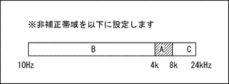
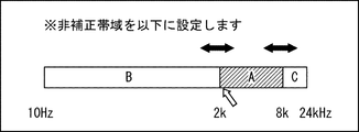
- FIGS. 5, 7, 9, and 11 are examples of display screens for accepting an operation for setting the non-correction band.
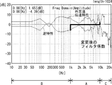
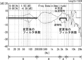
- FIG. 6, 8, 10, and 12 are diagrams illustrating the inverse characteristics in which the filter coefficients are changed, that is, the amplitude characteristics of the correction filter.
- the display unit 34 displays an initial setting screen as shown in FIG.
- a bar for setting the non-correction band is displayed.
- a bar (hatched portion) corresponding to the non-correction band is displayed in a frame indicating the entire frequency band of 10 Hz to 24 kHz.
- the uncorrected band is set according to the position and width of the bar.
- 4 kHz to 8 kHz is set as the initial value of the non-correction band A.
- a frequency band (10 Hz to 4 kHz) lower than the non-correction band A is a correction band B
- a frequency band (8 kHz to 24 kHz) higher than the non-correction band A is a correction band C.
- the non-correction band A is arranged between the correction band B and the correction band C.
- the user U sets the uncorrected band A by operating the mouse or the touch panel and adjusting the position and width of the bar.
- the reverse characteristics are as shown in FIG.
- the amplitude of the inverse filter is 0 dB.
- the filter coefficient of the correction filter in the non-correction band A is indicated by a bold line. That is, in FIG. 6, the filter coefficient changed by the correction filter generation unit 33 is indicated by a thick line.
- the correction bands B and C the same coefficients as the filter coefficients in FIG.
- FIG. 7 shows an example of a setting screen when changing the non-correction band A.
- the display unit 34 displays the setting screen shown in FIG.
- the bandwidth is constant and the start frequency (lower limit value) is adjusted.
- a white arrow indicates a cursor on the display screen, and a black arrow indicates to the user U that the range of the uncorrected band A can be changed.
- the non-correction band A has moved to the low frequency side compared to FIG.
- FIG. 8 shows the reverse characteristics when the non-correction band A shown in FIG. 7 is set.
- the amplitude of the inverse filter is 0 dB.
- the filter coefficient of the correction filter in the non-correction band A is indicated by a bold line.
- FIG. 9 shows an example of a setting screen for changing the bandwidth of the non-correction band A.
- the display unit 34 displays the setting screen shown in FIG.
- a black arrow indicates that the start frequency (lower limit value) and end frequency (upper limit value) of the non-correction band A can be changed.
- the non-correction band A can be widened from the initial setting (4 kHz to 8 kHz).
- the start frequency (lower limit value) of the uncorrected band A is 2 kHz
- the end frequency (upper limit value) is 8 kHz.
- the reverse characteristics when the uncorrected band A shown in FIG. 9 is set are as shown in FIG.
- the amplitude of the inverse filter is 0 dB.
- the filter coefficient of the correction filter in the non-correction band A is indicated by a bold line.
- the non-correction band A is expanded from the initial setting, but may be narrowed. Specifically, the start frequency and the end frequency are expanded or reduced at an equal ratio (logarithmic scale) by moving both ends of the bar to the left or right, or turning the mouse wheel.
- the non-correction band D is set on the lower frequency side than the non-correction band A of FIG.
- the uncorrected band D is set from 10 Hz to 200 Hz, which is the overall lower limit value.
- the user U can adjust the upper limit value of the non-correction band D by operating the mouse or the touch panel.
- the correction band B is arranged between the non-correction band A and the non-correction band D.
- FIG. 12 shows the reverse characteristics when the uncorrected bands A and D shown in FIG. 11 are set.
- the amplitude of the inverse filter is 0 dB.
- the filter coefficients of the correction filters in the non-correction bands A and D are indicated by bold lines.
- the lower limit value of the non-correction band D is the entire lower limit value 10 Hz. Therefore, the user U can freely set the end frequency (upper limit value) of the non-correction band D. In this way, two uncorrected bands A and D may be set. Of course, two or more uncorrected bands may be set.
- the correction filter generation unit 33 changes the filter coefficient in the non-correction band. Then, the correction filter generation unit 33 performs inverse discrete Fourier transform on the amplitude characteristic having the changed filter coefficient. Thus, the correction filter generation unit 33 generates a correction filter by changing the filter coefficient in the inverse filter in the non-correction band.
- the correction filter generated by the correction filter generation unit 33 is set as an inverse filter.
- the filter units 41 and 42 perform convolution processing on the Lch signal and the Rch signal using a correction filter. Then, the filter unit 41 outputs the Lch signal in which the left correction filter is convoluted to the left unit 42L of the filter unit 42.
- the filter unit 42 outputs the Rch signal in which the right correction filter is convoluted to the right unit 42 ⁇ / b> R of the headphones 43.
- the user U can set an uncorrected band on the frequency axis by operating the input unit 31.
- the correction filter generation unit 33 sets the filter coefficient to 0 dB. That is, the correction filter generation unit 33 generates a correction filter in which the filter coefficient in the non-correction band is 0.
- the filter unit 41 and the filter unit 42 perform a convolution process using the correction filter generated by the correction filter generation unit 33. In this way, the sound image can be localized out of the head while the sound quality of the headphones remains. Even when headphones are used, it is possible to perform out-of-head localization with sound quality preferable for the user.
- the non-correction band A is preferably set so as to include a band of 4 kHz to 8 kHz. Furthermore, it is preferable that the low frequency side non-correction band D includes a band of 500 Hz or less.
- the correction band B between the non-correction band A and the non-correction band D is preferably 1 kHz to 4 kHz. This is because the band that requires out-of-head localization processing is considered to be 1 kHz to 4 kHz, which has the highest sensitivity in terms of hearing. Therefore, the start frequency (lower limit value) of the non-correction band A is preferably 4 kHz or more, and more preferably 5 kHz or more.
- the end frequency of the non-correction band D is 500 Hz or more and 1 kHz or less. These frequencies were obtained based on experiments by a plurality of subjects. Further, by using these frequencies, the ear canal transfer characteristic is corrected at 1 kHz to 4 kHz, which is the most sensitive to human hearing.
- the end frequency (upper limit value) of the non-correction band A is preferably 8 kHz or less.
- Non-Patent Document 1 Since the user U can set the non-correction band, it is possible to prevent the localization position from changing or the sound image from being blurred, and the entire sound field from being lost. For example, it can be corrected in a wider band than in Non-Patent Document 1. It is possible to localize a sound image of one musical instrument (for example, a pipe organ or a piano) composed of a wideband frequency component without blurring. Also, in instruments with a rich harmonic structure (for example, violin, oboe, or piano bass), the localization of unfiltered low frequency overtones and filtered high frequency overtones is connected from the head to the head. Can be prevented.
- a rich harmonic structure for example, violin, oboe, or piano bass
- the balance between headphone sound quality and out-of-head localization can be adjusted according to the user's preference.
- the headphone sound quality mode, speaker sound quality mode, and intermediate sound quality mode may be switched.
- the mode may be switched by the headphones 43 or a switch or button provided in the input unit 31.
- the display unit 34 may display the corrected filter amplitude characteristic in accordance with an operation on the input unit 31.
- the filter processing is performed without changing the filter coefficient of the inverse filter. Therefore, the filter unit 41 and the filter unit 42 perform a convolution process using an inverse filter as shown in FIG. Therefore, sound field reproduction with the highest out-of-head localization feeling can be achieved with the sound quality of the speakers used for measuring the transfer characteristics Ls, Lo, Ro, and Rs.
- the filter coefficient is 0 dB in the entire frequency band.
- the filter unit 41 and the filter unit 42 do not perform the filter process. Therefore, the Lch signal and the Rch signal that have been subjected to the convolution process in the out-of-head localization processing unit 10 are output toward the user U from the left unit 43L and the right unit 43R of the headphones 43, respectively.
- sound field reproduction with a sense of out-of-head localization can be performed while maintaining the sound quality peculiar to headphones.
- the correction filter generation unit 33 performs the convolution processing using the correction filter as described above. That is, the filter unit 41 and the filter unit 42 fold the left and right correction filters into the Lch signal and the Rch signal, respectively. Then, the Lch signal and the Rch signal in which the correction filter is convoluted are output to the user U from the left unit 43L and the right unit 43R of the headphones 43, respectively.
- the filter coefficient is 0 dB in the non-correction band, and the filter coefficient of the inverse filter is used as it is in the correction band other than the non-correction band. Since the convolution process is performed using such a correction filter, sound field reproduction with a high out-of-head localization feeling can be performed while leaving the sound quality of the headphones moderate.
- out-of-head localization processing may be switched on and off by the out-of-head localization processing unit 10. Even if the out-of-head localization processing is turned off, if the sound is reproduced in the intermediate sound quality mode, the change in sound quality at the time of switching can be reduced.
- the inverse filter storage unit 32 stores the inverse filter of the ear canal transfer characteristic of the earphone, and the filter unit 41 and the filter unit 42 use the inverse filter.
- the output unit that outputs the reproduction signal subjected to the out-of-head localization processing to the user may have the headphones 43 or the earphones.
- the out-of-head localization processing method is an out-of-head localization processing method that performs out-of-head localization using an inverse filter of the ear canal transfer characteristic, and sets an uncorrected band based on an input from a user.
- a step of generating a correction filter by changing a filter coefficient of the non-correction band in the inverse filter, a step of performing a convolution process on the reproduction signal using a spatial acoustic transfer characteristic, and a convolution A step of convolving the correction filter with respect to the processed reproduction signal; and a step of outputting the reproduction signal with the correction filter convoluted to a user from a headphone or an earphone. is there.
- Non-transitory computer readable media include various types of tangible storage media.
- Examples of non-transitory computer-readable media include magnetic recording media (for example, flexible disks, magnetic tapes, hard disk drives), magneto-optical recording media (for example, magneto-optical disks), CD-ROMs (Read Only Memory), CD-Rs, CD-R / W, semiconductor memory (for example, mask ROM, PROM (Programmable ROM), EPROM (Erasable PROM), flash ROM, RAM (Random Access Memory)).
- the program may be supplied to a computer by various types of temporary computer readable media.
- Examples of transitory computer readable media include electrical signals, optical signals, and electromagnetic waves.
- the temporary computer-readable medium can supply the program to the computer via a wired communication path such as an electric wire and an optical fiber, or a wireless communication path.
- the present application is applicable to an out-of-head localization processing apparatus that outputs a reproduction signal subjected to out-of-head localization processing from headphones or earphones.
Landscapes
- Physics & Mathematics (AREA)
- Engineering & Computer Science (AREA)
- Acoustics & Sound (AREA)
- Signal Processing (AREA)
- Stereophonic System (AREA)
Abstract
本実施の形態にかかる頭外定位処理装置(100)は、外耳道伝達特性の逆フィルタを用いて頭外定位を行う頭外定位処理装置であって、周波数軸上の非補正帯域を設定するための入力を受け付ける入力部(31)と、非補正帯域において、逆フィルタのフィルタ係数を変更することで、補正フィルタを生成する補正フィルタ生成部(33)と、空間音響伝達特性を用いて、再生信号に対して畳み込み処理を行う畳み込み演算部(11、12、21、22)と、補正フィルタを用いて、畳み込み演算部で処理された再生信号に対して畳み込む処理を行うフィルタ部(41、42)と、補正フィルタが畳み込まれた再生信号をユーザ(U)に向けて出力するヘッドホン(43)と、を備えたものである。
Description
本発明は、頭外定位処理装置、頭外定位処理方法、プログラムに関する。
特許文献1には、従来、頭外に音像を定位させる方法として、受聴者の頭部伝達関数HRTF(Head Related Transfer Function)が記載されている。特許文献1に記載の方法では、ヘッドホン又はイヤホンを用いる場合、仮想音源から受聴者の両耳までの頭部伝達関数と、外耳道伝達関数ECTF(Ear Canal Transfer function)との逆特性を再生信号に畳み込んでいる。こうすることで、ヘッドホン又はイヤホンの特性をキャンセルして、耳の近傍から音が出ているにもかかわらず、仮想音源方向から音が聞こえているかのように音場を再生することができる。受聴者の外耳道内に測定マイクを挿入、又はダミーヘッドで代用することで、外耳道伝達関数ECTFの測定が行われる。
"帯域通過雑音による水平面音像定位" 森川大輔、平原達也 電子情報通信学会論文誌A Vol.J95-A No.4 pp337-342
外耳道伝達関数ECTFは、ヘッドホン又はイヤホン特有の音を決定づける伝達関数である。外耳道伝達関数ECTFには、音質に関わる周波数振幅特性と、鼓膜をどのような位相で振動させるかに関わる位相特性とが含まれている。ところが、頭外定位処理は外耳道伝達関数ECTFの逆特性を畳み込むため、ヘッドホン又はイヤホン特有の音質や迫力が得られなくなる場合がある。よって、ユーザにとって好ましい音質で頭外定位することができない場合がある。
特に、頭外定位処理のON/OFFを比較すると、音質の変化が大きくなる。すなわち、頭外定位処理の処理音と、ヘッドホンそのものの音を比較すると、音質が大きく変わってしまう。そのため、ヘッドホンの音質を残したままの頭外定位処理が望まれている。
また、非特許文献1には、狭帯域雑音の定位について、白色雑音と同程度の定位精度を出すためには、2kHz~12kHzが必要と記載されている。しかしながら、ステレオ音楽のような広帯域の音源に対して、この狭帯域のみ頭外定位処理したとしても、定位位置が変化したり、音像がぼやけたり、音場全体のまとまりがなくなってしまう場合がある。
本実施形態は上記の点に鑑みなされたもので、ヘッドホン又はイヤホンを用いた場合でも、ユーザにとって好ましい音質で頭外定位することができる頭外定位処理装置、頭外定位処理方法、及びプログラムを提供することを目的とする。
本実施形態の一態様にかかる頭外定位処理装置は、外耳道伝達特性の逆フィルタを用いて頭外定位処理を行う頭外定位処理装置であって、周波数軸上の非補正帯域を設定するための入力を受け付ける入力部と、前記非補正帯域において、前記逆フィルタのフィルタ係数を変更することで、補正フィルタを生成する補正フィルタ生成部と、空間音響伝達特性を用いて、再生信号に対して畳み込み処理を行う畳み込み演算部と、前記補正フィルタを用いて、前記畳み込み演算部で処理された前記再生信号に対して畳み込み処理を行うフィルタ部と、ヘッドホン又はイヤホンを有し、前記フィルタ部で畳み込み処理された再生信号をユーザに向けて出力する出力部と、を備えたものである。
本実施形態の一態様にかかる頭外定位処理方法は、外耳道伝達特性の逆フィルタを用いて頭外定位を行う頭外定位処理方法であって、ユーザからの入力に基づいて、非補正帯域を設定するステップと、前記逆フィルタにおいて、前記非補正帯域のフィルタ係数を変更することで、補正フィルタを生成するステップと、空間音響伝達特性を用いて、再生信号に対して畳み込み処理を行うステップと、畳み込み処理された前記再生信号に対して、前記補正フィルタを畳み込み処理するステップと、前記補正フィルタが畳み込まれた再生信号を、ヘッドホン又はイヤホンからユーザに向けて出力するステップと、を備えたものである。
本実施形態の一態様にかかるプログラムは、外耳道伝達特性の逆フィルタを用いて頭外定位処理を行う頭外定位処理方法をコンピュータに実行させるためのプログラムであって、前記頭外定位処理方法が、ユーザからの入力に基づいて、非補正帯域を設定するステップと、前記逆フィルタにおいて、前記非補正帯域のフィルタ係数を変更することで、補正フィルタを生成するステップと、空間音響伝達特性を用いて、再生信号に対して畳み込み処理を行うステップと、畳み込み処理された前記再生信号に対して、前記補正フィルタを畳み込み処理するステップと、前記補正フィルタが畳み込まれた再生信号を、ヘッドホン又はイヤホンからユーザに向けて出力するステップと、を備えた、ものである。
本実施形態によれば、ヘッドホン又はイヤホンを用いた場合でも、ユーザにとって好ましい音質で頭外定位することができる頭外定位処理装置、頭外定位処理方法、及びプログラムを提供できる。
本実施の形態にかかる頭外定位処理の概要について説明する。
本実施形態にかかる頭外定位処理は、個人の空間音響伝達特性(空間音響伝達関数ともいう)あるいは外耳道伝達特性(外耳道伝達関数ともいう)を用いて頭外定位処理を行うものである。本実施形態では、スピーカから聴取者の耳までの空間音響伝達特性、及びヘッドホンを装着した状態での外耳道伝達特性を用いて頭外定位処理を実現している。
本実施形態にかかる頭外定位処理は、個人の空間音響伝達特性(空間音響伝達関数ともいう)あるいは外耳道伝達特性(外耳道伝達関数ともいう)を用いて頭外定位処理を行うものである。本実施形態では、スピーカから聴取者の耳までの空間音響伝達特性、及びヘッドホンを装着した状態での外耳道伝達特性を用いて頭外定位処理を実現している。
本実施の形態では、ヘッドホン装着状態でのヘッドホンスピーカユニットから外耳道入口までの特性である外耳道伝達特性を利用している。そして、外耳道伝達特性の逆特性(外耳道補正関数ともいう)を示す逆フィルタを用いてフィルタ処理を行うことで、外耳道伝達特性を補正する。これにより、外耳道伝達特性をキャンセルすることができる。
さらに、ユーザからの入力に応じて、外耳道伝達特性補正を行わない非補正帯域を設定する。すなわち、ヘッドホンで再生可能な全周波数帯域において、一部の帯域を非補正帯域として設定する。具体的には、外耳道伝達特性の逆フィルタにおいて、ユーザからの入力により設定された非補正帯域のフィルタ係数を変更する。非補正帯域では逆フィルタによる外耳道伝達特性補正を行わないように逆フィルタのフィルタ係数を0dBとする。このようにすることで、ヘッドホンの音質をどの程度反映させるかを設定することができる。よって、ヘッドホンのユーザにとって好ましい音質で頭外定位することができる。
例えば、ユーザが非補正帯域を設定するための入力を行う。すると、本実施の形態の頭外定位処理装置は、予め設定された逆フィルタのフィルタ係数の内、非補正帯域におけるフィルタ係数が0dBとなるように設定する。次に、本実施の形態の頭外定位処理装置は、非補正帯域のフィルタ係数が変更された逆フィルタを補正フィルタとし、補正フィルタを再生信号に畳み込む。そして、本実施の形態の頭外定位処理装置は、補正フィルタが畳み込まれた再生信号をヘッドホン又はイヤホンから出力する。このようにすることで、ヘッドホン特有の音質を残しながら、頭外定位処理を行うことができる。
また、フィルタ係数を0dBとする非補正帯域を可変とすることも可能である。例えば、ユーザが非補正帯域の幅、及び位置(周波数)を調整できるようにしてもよい。このようにすることで、ユーザが好みの音質になるように調整することができる。
本実施の形態にかかる頭外定位処理装置は、パーソナルコンピュータなどの情報処理装置であり、プロセッサ等の処理手段、メモリやハードディスクなどの記憶手段、液晶モニタ等の表示手段、タッチパネル、ボタン、キーボード、マウスなどの入力手段、ヘッドホン又はイヤホンを有する出力手段を備えている。あるいは、頭外定位処理装置は、スマートホンやタブレットPCであってもよい。
本実施の形態にかかる頭外定位処理装置100を図1に示す。図1は、頭外定位処理装置のブロック図である。頭外定位処理装置100は、ヘッドホン43を装着するユーザUに対して音場を再生する。そのため、頭外定位処理装置100は、左チャンネル(以下Lchと記載する)と右チャンネル(以下Rchと記載する)のステレオ入力信号XL、XRについて、頭外定位処理を行う。LchとRchのステレオ入力信号XL、XRは、CD(Compact Disc)プレーヤなどから出力される音楽再生信号である。なお、頭外定位処理装置100は、物理的に単一な装置に限られるものではなく、一部の処理が異なる装置で行われてもよい。例えば、一部の処理がパソコンなどにより行われ、残りの処理がヘッドホン43に内蔵されたDSP(Digital Signal Processor)などにより行われてもよい。
頭外定位処理装置100は、頭外定位処理部10と、入力部31、逆フィルタ記憶部32、補正フィルタ生成部33、表示部34、フィルタ部41、フィルタ部42、及びヘッドホン43を備えている。
頭外定位処理部10は、畳み込み演算部11、12、21、22を備えている。畳み込み演算部11、12、21、22は、空間音響伝達特性を用いた畳み込み処理を行う。頭外定位処理部10には、CDプレーヤなどからのステレオ入力信号XL、XRが入力される。頭外定位処理部10には、空間音響伝達特性が設定されている。頭外定位処理部10は、各チャンネルのステレオ入力信号XL、XRに対し、空間音響伝達特性を畳み込む。空間音響伝達特性は頭部伝達関数HRTFであってもよい。
空間音響伝達特性は、4つの伝達特性Ls、Lo、Ro、Rsを有している。4つの伝達特性は、図2に示すような測定装置を用いて、求めることができる。図2では、受聴者1の前方に左スピーカ5Lと右スピーカ5Rが設置されている。また、受聴者1の左耳3Lの外耳道入口、又は鼓膜位置に収音用のマイク2Lが設置される。受聴者1の右耳3Rの外耳道入口、又は鼓膜位置に収音用のマイク2Rが設置される。なお、受聴者1は、人でもよく、ダミーヘッドでもよい。したがって、本実施形態において、受聴者1は人だけでなく、ダミーヘッドを含む概念である。
左スピーカ(SpL)5Lからのインパルス応答を左のマイク2L、及び右のマイク2Rで測定する。これにより、左スピーカ5Lと左のマイク2L間の伝達特性(伝達関数ともいう)Lsと、左スピーカ5Lと右のマイク2R間の伝達特性Loを得ることができる。また、右スピーカ(SpR)5Rからのインパルス応答を左のマイク2L、及び右のマイク2Rで測定する。これにより、右スピーカ5Rと左のマイク2L間の伝達特性Roと、右スピーカ5Rと右のマイク2R間の伝達関数Rsを求めることができる。このように、ある受聴者1に対して2回のインパルス応答測定を行うことで、4つの伝達特性Ls、Lo、Ro、Rsが得られる。あるいは、ユーザUがプリセットされた複数の空間音響伝達特性のうちの適切なものを選択することで、空間音響伝達特性を設定するようにしてもよい。したがって、図2における受聴者1と図1におけるユーザUは同一人物であってもよく、異なる人物であってもよい。当然、受聴者1とユーザUとが異なるよりも、同一であるほうが頭外定位処理の効果は高い。
そして、畳み込み演算部11は、Lchのステレオ入力信号XLに対して伝達特性Lsを畳み込む。畳み込み演算部11は、畳み込み演算データを加算器24に出力する。畳み込み演算部21は、Rchのステレオ入力信号XRに対して伝達特性Roを畳み込む。畳み込み演算部21は、畳み込み演算データを加算器24に出力する。加算器24は2つの畳み込み演算データを加算して、フィルタ部41に出力する。
畳み込み演算部12は、Lchのステレオ入力信号XLに対して伝達特性Loを畳み込む。畳み込み演算部12は、畳み込み演算データを、加算器25に出力する。畳み込み演算部22は、Rchのステレオ入力信号XRに対して伝達特性Rsを畳み込む。畳み込み演算部22は、畳み込み演算データを、加算器25に出力する。加算器25は2つの畳み込み演算データを加算して、フィルタ部42に出力する。
フィルタ部41、42には外耳道伝達特性に応じた逆フィルタが設定されている。そして、頭外定位処理部10での処理が施された再生信号に逆フィルタを畳み込む。フィルタ部41で加算器24からのLch信号に対して、逆フィルタを畳み込む。同様に、フィルタ部42は加算器25からのRch信号に対して逆フィルタを畳み込む。逆フィルタは、ヘッドホン43を装着した場合に、ユーザ各人の外耳道入口とスピーカ間の伝達特性をキャンセルする。このようにすることで、ヘッドホン43の特性が補正(キャンセル)される。なお、ダミーヘッドを用いる場合は鼓膜位置にマイク2R、2Lを設置できるため、この場合の逆フィルタは、鼓膜とヘッドホンスピーカユニット間の伝達特性をキャンセルすることになる。
フィルタ部41は、補正されたLch信号をヘッドホン43の左ユニット43Lに出力する。フィルタ部42は、補正されたRch信号をヘッドホン43の右ユニット43Rに出力する。ユーザUは、ヘッドホン43を装着している。ヘッドホン43は、Lch信号とRch信号をユーザUに向けて出力する。これにより、ユーザUが受聴する音の音像は、ユーザUの頭外に定位される。
表示部34は、液晶モニタなどの表示デバイスを備えている。後述するように、表示部34は、非補正帯域の設定画面等を表示する。
入力部31は、タッチパネル、ボタン、キーボード、マウスなどの入力デバイスを有しており、ユーザUからの入力を受け付ける。具体的には、入力部31は、周波数軸上の非補正帯域を設定するための入力を受け付ける。また、入力部31はヘッドホン43に搭載されたスイッチ等であってもよい。ユーザUは、入力部31を操作することで、フィルタ係数の補正を行う周波数軸上の非補正帯域を設定する。そして、設定された非補正帯域が、補正フィルタ生成部33に出力される。例えば、非補正帯域の上限値、及び下限値が補正フィルタ生成部33に出力される。なお、全周波数帯域において、非補正帯域が2以上あってもよい。
逆フィルタ記憶部32には、フィルタ部41、42での畳み込み処理に用いられる外耳道伝達特性の逆フィルタ(逆特性)が記憶されている。なお、外耳道伝達特性は、予め計測しておいたものを用いてもよいし、いくつかのプリセットされた特性から選択してもよい。外耳道伝達特性の測定には、例えばダミーヘッドやユーザUに対するインパルス応答測定が用いられる。ダミーヘッド又はユーザUに対してマイクを装着して、インパルス応答を測定する。図3にインパルス応答測定により得られた外耳道伝達特性とその逆特性の一例を示す。
測定により得られた外耳道インパルス応答を離散フーリエ変換して、時間領域から周波数領域に変換する。これにより、各周波数の振幅特性(振幅スペクトル、パワースペクトル)と位相特性(位相スペクトル)とが算出される。そして、振幅特性の逆特性を外耳道伝達特性の逆フィルタとする。
この際、高周波数帯域における受聴者の違和感を抑制するため、特許文献2に記載の平滑化処理を行うことが望ましい。具体的には高域境界周波数よりもさらに高域側(本実施の形態においては14kHz以上)において、外耳道伝達関数の振幅特性に関わらず、逆フィルタの振幅成分を一定値(本実施の形態においては0dB)とする。ここで、高域境界周波数は、頭外音像定位処理を実施する周波数帯域のうち、高域側の境界周波数を指す。この平滑化処理により、周波数振幅特性のノッチに起因する高音ノイズの発生を防止できる。
なお、平滑化処理した周波数帯域は、本発明の非補正帯域には含まないこととする。
なお、平滑化処理した周波数帯域は、本発明の非補正帯域には含まないこととする。
図4は、外耳道伝達特性と平滑化逆特性の周波数振幅特性を示す図であり、図3に示す外耳道インパルス応答を離散フーリエ変換した周波数領域の外耳道伝達特性の逆特性を示している。図4において、横軸が対数尺度の周波数(Hz)であり、縦軸が振幅(dB)である。外耳道伝達特性の周波数領域における各周波数での振幅がフィルタ係数となる。なお、図4に示す周波数軸上の逆特性を逆離散フーリエ変換すると、図3に示す逆応答となる。
補正フィルタ生成部33は、逆フィルタ記憶部32に記憶された逆フィルタのフィルタ係数を読み出して、補正フィルタを生成する。補正フィルタ生成部33は、予め求められている外耳道伝達特性の逆フィルタのフィルタ係数を変更することで、補正フィルタを生成する。例えば、補正フィルタ生成部33は、非補正帯域における逆フィルタのフィルタ係数を0dBに変更する。このようにして、補正フィルタ生成部33は、補正フィルタを生成する。さらに、補正フィルタ生成部33は、フィルタ係数が変更された逆フィルタを逆離散フーリエ変換することで、補正フィルタを時間領域のフィルタにしてもよい。
非補正帯域の設定において、ユーザは、ヘッドホンの音質を残す割合を入力することができる。例えば、ユーザが0~100%の内の割合を入力すると、割合に応じて非補正帯域が設定される。具体的には、全周波数帯域に対して、外耳道伝達特性を補正しない非補正帯域の割合をユーザUが数値入力する。この割合は対数尺度とすることが望ましい。
全周波数帯域を10Hz~24kHzとし、サンプリング周波数Fs=48kHzであるとする。非補正帯域の開始周波数(下限値)をFstartとし、非補正帯域の終了周波数(上限値)をFendとする。この場合、以下の式(1)により、対数尺度の割合が求められる。なお、全周波数帯域の下限は10Hzに限らず、例えば0Hzや20Hzでも構わない。
100・(logFend-logFstart)/(log24000-log10) ・・・(1)
100・(logFend-logFstart)/(log24000-log10) ・・・(1)
非補正帯域の初期値が4kHz~8kHzの場合、全周波数帯域10Hz~24kHzに対する非補正帯域の割合は、約9%となる。ユーザが、この割合を増加させた場合は、開始周波数(下限値)が低い方、終了周波数(上限値)が高い方へそれぞれ移動する。
非補正帯域の割合を100%とすれば、外耳道伝達特性が全く補正されなくなり、ヘッドホンの音質100%の頭外定位処理が実行される。これをヘッドホン音質モードと呼ぶ。反対に、非補正帯域の割合を0%とすれば、全周波数帯域で補正が行われるため、測定したスピーカの音質そのものになる。これをスピーカ音質モードと呼ぶ。一方、上記のように非補正帯域におけるフィルタ係数の一部が変更された補正フィルタを用いる場合を中間音質モードと呼ぶ。このように、割合を入力することで、モードを切り替えることができる。
以下、図5~12を用いて、非補正帯域の設定について、詳細に説明する、図5、図7、図9、図11は、非補正帯域を設定するための操作を受け付ける表示画面の一例を示す図である。図6、図8、図10、図12は、フィルタ係数が変更された逆特性、即ち補正フィルタの振幅特性を示す図である。
まず、表示部34が図5に示すような初期設定画面を表示する。図5では、非補正帯域を設定するためのバーを表示する。具体的には、全体の周波数帯域である10Hz~24kHzを示す枠内に、非補正帯域に対応するバー(ハッチング部分)が表示される。バーの位置、及び幅によって非補正帯域が設定される。ここでは、非補正帯域Aの初期値として、4kHz~8kHzが設定されている。なお、非補正帯域Aよりも低い周波数帯域(10Hz~4kHz)を補正帯域Bとして、非補正帯域Aよりも高い周波数帯域(8kHz~24kHz)を補正帯域Cとする。非補正帯域Aは補正帯域Bと補正帯域Cとの間に配置される。具体的には、ユーザUはマウス又はタッチパネルを操作して、バーの位置、及び幅を調整することで、非補正帯域Aを設定する。
4kHz~8kHzが非補正帯域Aとする場合、逆特性は、図6に示すようになる。非補正帯域Aでは逆フィルタの振幅が0dBとなる。図6では、非補正帯域Aにおける補正フィルタのフィルタ係数を太線で示している。すなわち、図6では、補正フィルタ生成部33によって変更されたフィルタ係数が太線で示されている。補正帯域B、Cでは、図4のフィルタ係数と同じ係数となる。
図7に、非補正帯域Aを変更する場合の設定画面の一例を示す。表示部34が図7に示す設定画面を表示する。図7では帯域幅を一定として、開始周波数(下限値)を調整する。図7において、白抜き矢印は表示画面上のカーソルを示し、黒矢印は非補正帯域Aの範囲が変更可能であることをユーザUに示している。図7では、図5に比べて非補正帯域Aが低周波数側に移動している。
図7に示す非補正帯域Aが設定された場合の逆特性は図8に示すようになる。非補正帯域Aでは逆フィルタの振幅が0dBとなる。図8では、非補正帯域Aにおける補正フィルタのフィルタ係数を太線で示している。補正帯域B、Cでは、図4のフィルタ係数と同じ係数となる。
図9に、非補正帯域Aの帯域幅を変更する場合の設定画面の一例を示す。表示部34が図9に示す設定画面を表示する。図9では、非補正帯域Aの開始周波数(下限値)と終了周波数(上限値)が変更可能であることが黒矢印で示されている。図9に示すように、非補正帯域Aを初期設定(4kHz~8kHz)から広くすることができる。図9では、非補正帯域Aの開始周波数(下限値)が2kHzとなっており、終了周波数(上限値)が8kHzとなっている。
図9に示す非補正帯域Aが設定された場合の逆特性は図10に示すようになる。非補正帯域Aでは逆フィルタの振幅が0dBとなる。図10では、非補正帯域Aにおける補正フィルタのフィルタ係数を太線で示している。補正帯域B、Cでは、図4のフィルタ係数と同じ係数となる。なお、図9では、非補正帯域Aを初期設定から広げたが、狭くしてもよい。具体的にはバーの両端をそれぞれ左右へ移動させる、あるいはマウスのホイールを回すこと等により、開始周波数と終了周波数が等しい割合(対数尺度)で拡張又は縮小する。
さらに、図11、図12に示すように非補正帯域を2つ設定することも可能である。図11では、図6の非補正帯域Aよりも低周波数側に非補正帯域Dが設定されている。非補正帯域Dは全体の下限値である10Hzから200Hzに設定されている。ユーザUはマウス又はタッチパネルを操作することで、非補正帯域Dの上限値を調整することができる。補正帯域Bが非補正帯域Aと非補正帯域Dとの間に配置される。
図11に示す非補正帯域A、Dが設定された場合の逆特性は図12に示すようになる。非補正帯域A、Dでは逆フィルタの振幅が0dBとなる。図12では、非補正帯域A、Dにおける補正フィルタのフィルタ係数を太線で示している。補正帯域B、Cでは、図4のフィルタ係数と同じ係数となる。非補正帯域Dの下限値は、全体の下限値10Hzとなっている。よって、ユーザUは、非補正帯域Dの終了周波数(上限値)を自由に設定することができる。このように、2つの非補正帯域A、Dを設定するようにしてもよい。もちろん、2以上の非補正帯域を設定するようにしてもよい。
上述したように、非補正帯域において、補正フィルタ生成部33はフィルタ係数を変更する。そして、補正フィルタ生成部33は、変更されたフィルタ係数を有する振幅特性を逆離散フーリエ変換する。このように、補正フィルタ生成部33は、非補正帯域において、逆フィルタにおけるフィルタ係数を変更することで、補正フィルタを生成する。フィルタ部41、42には、補正フィルタ生成部33で生成された補正フィルタが逆フィルタとして設定される。フィルタ部41、42は、補正フィルタを用いて、Lch信号、及びRch信号に畳み込み処理を行う。そして、フィルタ部41は、左の補正フィルタが畳み込まれたLch信号をフィルタ部42の左ユニット42Lに出力する。フィルタ部42は、右の補正フィルタが畳み込まれたRch信号をヘッドホン43の右ユニット42Rに出力する。
本実施の形態では、ユーザUが入力部31を操作することで、周波数軸上の非補正帯域を設定することができる。ユーザUの入力に応じて設定された非補正帯域において、補正フィルタ生成部33がフィルタ係数を0dBとしている。すなわち、補正フィルタ生成部33は、非補正帯域におけるフィルタ係数が0となる補正フィルタを生成する。補正フィルタ生成部33が生成した補正フィルタを用いて、フィルタ部41、フィルタ部42が畳み込み処理を行っている。このようにすることで、ヘッドホンの音質を残したまま、音像を頭外に定位することができる。ヘッドホンを用いた場合でも、ユーザにとって好ましい音質で頭外定位することができる。
非補正帯域Aは、4kHz~8kHzの帯域を含むように設定することが好ましい。さらに、低周波数側の非補正帯域Dは、500Hz以下の帯域を含むようにすることが好ましい。換言すると、非補正帯域Aと非補正帯域Dとの間の補正帯域Bは、1kHz~4kHzとすることが好ましい。頭外定位処理が必要な帯域は、聴感上最も感度が高い1kHz~4kHzと考えられているからである。よって、非補正帯域Aの開始周波数(下限値)を4kHz以上とすることが好ましく、さらに5kHz以上とすることがより好ましい。また、非補正帯域Dの終了周波数は500Hz以上とし、1kHz以下とする。これらの周波数は、複数名の被験者による実験に基づいて得られたものである。また、これらの周波数を用いることで、人間の聴感上最も感度が高い1kHz~4kHzにおいて、外耳道伝達特性が補正される。
さらに、高い周波数帯域に構成周波数を持つシンバルやトライアングルは約8kHz以上に多くの倍音が含まれている。よって、8kHz以上について、外耳道伝達特性を補正しないと、額周辺に音像が定位してしまう。よって、音像を頭外に定位させるためには、非補正帯域Aの終了周波数(上限値)を8kHz以下とすることが好ましい。こうすることで、ヘッドホン音質を適度に残したまま、適切に音像を定位させることができる。ヘッドホンを用いた場合でも、ユーザにとって好ましい音質で、頭外に定位することができる音場を再生することができる。
ユーザUが非補正帯域を設定することができるので、定位位置が変化したり、音像がぼやけたりして、音場全体のまとまりがなくなってしまうことを防げる。例えば、非特許文献1に比べて広帯域で補正することができる。広帯域の周波数成分で構成されている一つの楽器(例えば、パイプオルガンやピアノ)の音像をぼやけさせることなく定位させることができる。また、倍音構成の豊富な楽器(例えば、バイオリンやオーボエ、あるいはピアノの低音)では、フィルタ処理していない低域倍音と、フィルタ処理された高域倍音の定位が頭内から頭外につながってしまうことを防ぐことができる。さらに、特定の狭い帯域のみ定位が変わることを防げるため、全体としてまとまりがあり、違和感のない音場を再生することができる。音質の観点からのみ見ても、特定の狭い帯域だけスピーカの音質になることを防げるため、まとまりのある音質で再生することができる。よって、優れた音質での音場再生が可能になる。
上記のように非補正帯域を可変とすることで、本人の好みに合わせたヘッドホン音質と頭外定位のバランスを調整することができるようになる。なお、ヘッドホン音質モード、スピーカ音質モード、中間音質モード、を切替え可能にしてもよい。例えば、ヘッドホン43、又は入力部31に設けられたスイッチやボタンでモード切替するようにしてもよい。また、表示部34は、入力部31における操作に応じて、補正後のフィルタの振幅特性を表示してもよい。
スピーカ音質モードでは、逆フィルタのフィルタ係数を変更しないでフィルタ処理が行われる。したがって、フィルタ部41、フィルタ部42が、図4に示すような逆フィルタを用いて、畳み込み処理を行う。よって、伝達特性Ls、Lo、Ro、Rsの測定に用いられたスピーカの音質で、最も頭外定位感の高い音場再生ができる。
一方、ヘッドホン音質モードの場合、全周波数帯域においてフィルタ係数が0dBとなる。換言すると、フィルタ部41、フィルタ部42がフィルタ処理を行わない。よって、頭外定位処理部10で畳み込み処理が行われたLch信号とRch信号がそれぞれヘッドホン43の左ユニット43L、右ユニット43RからユーザUに向けて出力される。ヘッドホン音質モードでは、ヘッドホン特有の音質を維持したまま頭外定位感のある音場再生ができる。
一方、中間音質モードでは、上記のように補正フィルタ生成部33が補正フィルタを用いて、畳み込み処理が行われる。すなわち、フィルタ部41、フィルタ部42が左右の補正フィルタを、Lch信号、Rch信号にそれぞれ畳み込む。そして、補正フィルタが畳み込まれたLch信号とRch信号がそれぞれヘッドホン43の左ユニット43L、右ユニット43RからユーザUに向けて出力される。非補正帯域において外耳道伝達特性補正を行わない中間音質モードでは、上記のように、非補正帯域ではフィルタ係数が0dBとなり、非補正帯域以外の補正帯域では逆フィルタのフィルタ係数がそのまま用いられる。このような補正フィルタを用いて、畳み込み処理を行うため、ヘッドホンの音質を適度に残しながら、頭外定位感の高い音場再生ができる。
また、頭外定位処理部10により頭外定位処理のオンオフを切り替えるようにしてもよい。頭外定位処理をオフとしても、中間音質モードで再生していれば、切替え時の音質の変化を小さくすることができる。
なお、上記の説明ではヘッドホン43から音場を再生する例を説明したが、イヤホンによって、音場を再生してもよい。この場合、逆フィルタ記憶部32が、イヤホンの外耳道伝達特性の逆フィルタを格納しており、フィルタ部41、及びフィルタ部42がこの逆フィルタを用いる。頭外定位処理された再生信号をユーザに対して出力する出力部が、ヘッドホン43又はイヤホンを有していればよい。
本実施の形態にかかる頭外定位処理方法は、外耳道伝達特性の逆フィルタを用いて頭外定位を行う頭外定位処理方法であって、ユーザからの入力に基づいて、非補正帯域を設定するステップと、前記逆フィルタにおいて、前記非補正帯域のフィルタ係数を変更することで、補正フィルタを生成するステップと、空間音響伝達特性を用いて、再生信号に対して畳み込み処理を行うステップと、畳み込み処理された前記再生信号に対して、前記補正フィルタを畳み込み処理するステップと、前記補正フィルタが畳み込まれた再生信号を、ヘッドホン又はイヤホンからユーザに向けて出力するステップと、を備えたものである。
上記信号処理のうちの一部又は全部は、コンピュータプログラムによって実行されてもよい。上述したプログラムは、様々なタイプの非一時的なコンピュータ可読媒体(non-transitory computer readable medium)を用いて格納され、コンピュータに供給することができる。非一時的なコンピュータ可読媒体は、様々なタイプの実体のある記録媒体(tangible storage medium)を含む。非一時的なコンピュータ可読媒体の例は、磁気記録媒体(例えばフレキシブルディスク、磁気テープ、ハードディスクドライブ)、光磁気記録媒体(例えば光磁気ディスク)、CD-ROM(Read Only Memory)、CD-R、CD-R/W、半導体メモリ(例えば、マスクROM、PROM(Programmable ROM)、EPROM(Erasable PROM)、フラッシュROM、RAM(Random Access Memory))を含む。また、プログラムは、様々なタイプの一時的なコンピュータ可読媒体(transitory computer readable medium)によってコンピュータに供給されてもよい。一時的なコンピュータ可読媒体の例は、電気信号、光信号、及び電磁波を含む。一時的なコンピュータ可読媒体は、電線及び光ファイバ等の有線通信路、又は無線通信路を介して、プログラムをコンピュータに供給できる。
以上、本発明者によってなされた発明を実施の形態に基づき具体的に説明したが、本発明は上記実施の形態に限られたものではなく、その要旨を逸脱しない範囲で種々変更可能であることは言うまでもない。
この出願は、2015年7月23日に出願された日本出願特願2015-145801を基礎とする優先権を主張し、その開示の全てをここに取り込む。
本願は、頭外定位処理が施された再生信号をヘッドホン又はイヤホンから出力する頭外定位処理装置に適用可能である。
10 頭外定位処理部
11 畳み込み演算部
12 畳み込み演算部
21 畳み込み演算部
22 畳み込み演算部
24 加算器
25 加算器
31 入力部
32 逆フィルタ記憶部
33 補正フィルタ生成部
41 フィルタ部
42 フィルタ部
43 ヘッドホン
100 頭外定位処理装置
11 畳み込み演算部
12 畳み込み演算部
21 畳み込み演算部
22 畳み込み演算部
24 加算器
25 加算器
31 入力部
32 逆フィルタ記憶部
33 補正フィルタ生成部
41 フィルタ部
42 フィルタ部
43 ヘッドホン
100 頭外定位処理装置
Claims (5)
- 外耳道伝達特性の逆フィルタを用いて頭外定位処理を行う頭外定位処理装置であって、
周波数軸上の非補正帯域を設定するための入力を受け付ける入力部と、
前記非補正帯域において、前記逆フィルタのフィルタ係数を変更することで、補正フィルタを生成する補正フィルタ生成部と、
空間音響伝達特性を用いて、再生信号に対して畳み込み処理を行う畳み込み演算部と、
前記補正フィルタを用いて、前記畳み込み演算部で処理された前記再生信号に対して畳み込み処理を行うフィルタ部と、
ヘッドホン又はイヤホンを有し、前記フィルタ部で畳み込み処理された再生信号をユーザに向けて出力する出力部と、を備えた頭外定位処理装置。 - 前記非補正帯域では、前記逆フィルタのフィルタ係数が0dBに変更される請求項1に記載の頭外定位処理装置。
- 前記非補正帯域が2以上設けられている請求項1または2のいずれか1項に記載の頭外定位処理装置。
- 外耳道伝達特性の逆フィルタを用いて頭外定位を行う頭外定位処理方法であって、
ユーザからの入力に基づいて、非補正帯域を設定するステップと、
前記逆フィルタにおいて、前記非補正帯域のフィルタ係数を変更することで、補正フィルタを生成するステップと、
空間音響伝達特性を用いて、再生信号に対して畳み込み処理を行うステップと、
畳み込み処理された前記再生信号に対して、前記補正フィルタを畳み込み処理するステップと、
前記補正フィルタが畳み込まれた再生信号を、ヘッドホン又はイヤホンからユーザに向けて出力するステップと、を備えた頭外定位処理方法。 - 外耳道伝達特性の逆フィルタを用いて頭外定位処理を行う頭外定位処理方法をコンピュータに実行させるためのプログラムであって、
前記頭外定位処理方法が、
ユーザからの入力に基づいて、非補正帯域を設定するステップと、
前記逆フィルタにおいて、前記非補正帯域のフィルタ係数を変更することで、補正フィルタを生成するステップと、
空間音響伝達特性を用いて、再生信号に対して畳み込み処理を行うステップと、
畳み込み処理された前記再生信号に対して、前記補正フィルタを畳み込み処理するステップと、
前記補正フィルタが畳み込まれた再生信号を、ヘッドホン又はイヤホンからユーザに向けて出力するステップと、を備えた、プログラム。
Applications Claiming Priority (2)
| Application Number | Priority Date | Filing Date | Title |
|---|---|---|---|
| JP2015145801A JP6589437B2 (ja) | 2015-07-23 | 2015-07-23 | 頭外定位処理装置、頭外定位処理方法、プログラム |
| JP2015-145801 | 2015-07-23 |
Publications (1)
| Publication Number | Publication Date |
|---|---|
| WO2017013824A1 true WO2017013824A1 (ja) | 2017-01-26 |
Family
ID=57834917
Family Applications (1)
| Application Number | Title | Priority Date | Filing Date |
|---|---|---|---|
| PCT/JP2016/002564 Ceased WO2017013824A1 (ja) | 2015-07-23 | 2016-05-27 | 頭外定位処理装置、頭外定位処理方法、プログラム |
Country Status (2)
| Country | Link |
|---|---|
| JP (1) | JP6589437B2 (ja) |
| WO (1) | WO2017013824A1 (ja) |
Cited By (1)
| Publication number | Priority date | Publication date | Assignee | Title |
|---|---|---|---|---|
| EP3637801A4 (en) * | 2017-05-10 | 2020-12-23 | JVCKenwood Corporation | OUT-OF-HEAD LOCATION FILTER DETERMINATION SYSTEM, OFF-HEAD LOCATION FILTER DETERMINATION DEVICE, OUT-OF-HEAD LOCATION DETERMINATION PROCESS, AND PROGRAM |
Families Citing this family (4)
| Publication number | Priority date | Publication date | Assignee | Title |
|---|---|---|---|---|
| JP6866679B2 (ja) * | 2017-02-20 | 2021-04-28 | 株式会社Jvcケンウッド | 頭外定位処理装置、頭外定位処理方法、及び頭外定位処理プログラム |
| JP6950405B2 (ja) * | 2017-09-27 | 2021-10-13 | 株式会社Jvcケンウッド | 処理装置、処理方法、及びプログラム |
| JP7835165B2 (ja) * | 2021-01-29 | 2026-03-25 | ソニーグループ株式会社 | 情報処理装置、情報処理方法、およびプログラム |
| JPWO2024180610A1 (ja) * | 2023-02-27 | 2024-09-06 |
Citations (3)
| Publication number | Priority date | Publication date | Assignee | Title |
|---|---|---|---|---|
| JP2003009296A (ja) * | 2001-06-22 | 2003-01-10 | Matsushita Electric Ind Co Ltd | 音響処理装置および音響処理方法 |
| JP2005318061A (ja) * | 2004-04-27 | 2005-11-10 | Sony Corp | 信号処理装置およびバイノーラル再生方法 |
| JP2015126268A (ja) * | 2013-12-25 | 2015-07-06 | 株式会社Jvcケンウッド | 頭外音像定位装置、頭外音像定位方法、及び、プログラム |
Family Cites Families (2)
| Publication number | Priority date | Publication date | Assignee | Title |
|---|---|---|---|---|
| JP6102179B2 (ja) * | 2012-08-23 | 2017-03-29 | ソニー株式会社 | 音声処理装置および方法、並びにプログラム |
| JP6155698B2 (ja) * | 2013-02-28 | 2017-07-05 | 株式会社Jvcケンウッド | オーディオ信号処理装置、オーディオ信号処理方法、オーディオ信号処理プログラムおよびヘッドホン |
-
2015
- 2015-07-23 JP JP2015145801A patent/JP6589437B2/ja active Active
-
2016
- 2016-05-27 WO PCT/JP2016/002564 patent/WO2017013824A1/ja not_active Ceased
Patent Citations (3)
| Publication number | Priority date | Publication date | Assignee | Title |
|---|---|---|---|---|
| JP2003009296A (ja) * | 2001-06-22 | 2003-01-10 | Matsushita Electric Ind Co Ltd | 音響処理装置および音響処理方法 |
| JP2005318061A (ja) * | 2004-04-27 | 2005-11-10 | Sony Corp | 信号処理装置およびバイノーラル再生方法 |
| JP2015126268A (ja) * | 2013-12-25 | 2015-07-06 | 株式会社Jvcケンウッド | 頭外音像定位装置、頭外音像定位方法、及び、プログラム |
Cited By (1)
| Publication number | Priority date | Publication date | Assignee | Title |
|---|---|---|---|---|
| EP3637801A4 (en) * | 2017-05-10 | 2020-12-23 | JVCKenwood Corporation | OUT-OF-HEAD LOCATION FILTER DETERMINATION SYSTEM, OFF-HEAD LOCATION FILTER DETERMINATION DEVICE, OUT-OF-HEAD LOCATION DETERMINATION PROCESS, AND PROGRAM |
Also Published As
| Publication number | Publication date |
|---|---|
| JP2017028526A (ja) | 2017-02-02 |
| JP6589437B2 (ja) | 2019-10-16 |
Similar Documents
| Publication | Publication Date | Title |
|---|---|---|
| US9943253B2 (en) | System and method for improved audio perception | |
| US10264387B2 (en) | Out-of-head localization processing apparatus and out-of-head localization processing method | |
| JP6790654B2 (ja) | フィルタ生成装置、フィルタ生成方法、及びプログラム | |
| US11115743B2 (en) | Signal processing device, signal processing method, and program | |
| JP6515720B2 (ja) | 頭外定位処理装置、頭外定位処理方法、及びプログラム | |
| JP6589437B2 (ja) | 頭外定位処理装置、頭外定位処理方法、プログラム | |
| WO2009125567A1 (ja) | 挿耳型イヤホンを用いた音響再生装置 | |
| JP7115353B2 (ja) | 処理装置、処理方法、再生方法、及びプログラム | |
| JP2017017636A (ja) | 頭外定位フィルタ生成装置、頭外定位フィルタ生成方法、頭外定位処理装置、及び頭外定位処理方法 | |
| JP7384162B2 (ja) | 信号処理装置、信号処理方法、およびプログラム | |
| WO2018150766A1 (ja) | 頭外定位処理装置、頭外定位処理方法、及び頭外定位処理プログラム | |
| JP7031543B2 (ja) | 処理装置、処理方法、再生方法、及びプログラム | |
| JP7010649B2 (ja) | オーディオ信号処理装置及びオーディオ信号処理方法 | |
| JP6295988B2 (ja) | 音場再生装置、音場再生方法、音場再生プログラム | |
| JP6805879B2 (ja) | フィルタ生成装置、フィルタ生成方法、及びプログラム | |
| Vapalahti | Audio equalization based on personal hearing data | |
| JP2024001928A (ja) | 再生制御方法、及びプログラム | |
| JP2023024038A (ja) | 処理装置、及び処理方法 |
Legal Events
| Date | Code | Title | Description |
|---|---|---|---|
| 121 | Ep: the epo has been informed by wipo that ep was designated in this application |
Ref document number: 16827393 Country of ref document: EP Kind code of ref document: A1 |
|
| NENP | Non-entry into the national phase |
Ref country code: DE |
|
| 122 | Ep: pct application non-entry in european phase |
Ref document number: 16827393 Country of ref document: EP Kind code of ref document: A1 |