WO2017010275A1 - 電極組立体の製造装置、及び電極組立体の製造方法 - Google Patents
電極組立体の製造装置、及び電極組立体の製造方法 Download PDFInfo
- Publication number
- WO2017010275A1 WO2017010275A1 PCT/JP2016/069031 JP2016069031W WO2017010275A1 WO 2017010275 A1 WO2017010275 A1 WO 2017010275A1 JP 2016069031 W JP2016069031 W JP 2016069031W WO 2017010275 A1 WO2017010275 A1 WO 2017010275A1
- Authority
- WO
- WIPO (PCT)
- Prior art keywords
- electrode
- manufacturing
- unit
- buffer unit
- stock
- Prior art date
- Legal status (The legal status is an assumption and is not a legal conclusion. Google has not performed a legal analysis and makes no representation as to the accuracy of the status listed.)
- Ceased
Links
Images




Classifications
-
- H—ELECTRICITY
- H01—ELECTRIC ELEMENTS
- H01M—PROCESSES OR MEANS, e.g. BATTERIES, FOR THE DIRECT CONVERSION OF CHEMICAL ENERGY INTO ELECTRICAL ENERGY
- H01M10/00—Secondary cells; Manufacture thereof
- H01M10/04—Construction or manufacture in general
- H01M10/0404—Machines for assembling batteries
-
- H—ELECTRICITY
- H01—ELECTRIC ELEMENTS
- H01M—PROCESSES OR MEANS, e.g. BATTERIES, FOR THE DIRECT CONVERSION OF CHEMICAL ENERGY INTO ELECTRICAL ENERGY
- H01M10/00—Secondary cells; Manufacture thereof
- H01M10/05—Accumulators with non-aqueous electrolyte
- H01M10/058—Construction or manufacture
- H01M10/0585—Construction or manufacture of accumulators having only flat construction elements, i.e. flat positive electrodes, flat negative electrodes and flat separators
-
- Y—GENERAL TAGGING OF NEW TECHNOLOGICAL DEVELOPMENTS; GENERAL TAGGING OF CROSS-SECTIONAL TECHNOLOGIES SPANNING OVER SEVERAL SECTIONS OF THE IPC; TECHNICAL SUBJECTS COVERED BY FORMER USPC CROSS-REFERENCE ART COLLECTIONS [XRACs] AND DIGESTS
- Y02—TECHNOLOGIES OR APPLICATIONS FOR MITIGATION OR ADAPTATION AGAINST CLIMATE CHANGE
- Y02E—REDUCTION OF GREENHOUSE GAS [GHG] EMISSIONS, RELATED TO ENERGY GENERATION, TRANSMISSION OR DISTRIBUTION
- Y02E60/00—Enabling technologies; Technologies with a potential or indirect contribution to GHG emissions mitigation
- Y02E60/10—Energy storage using batteries
-
- Y—GENERAL TAGGING OF NEW TECHNOLOGICAL DEVELOPMENTS; GENERAL TAGGING OF CROSS-SECTIONAL TECHNOLOGIES SPANNING OVER SEVERAL SECTIONS OF THE IPC; TECHNICAL SUBJECTS COVERED BY FORMER USPC CROSS-REFERENCE ART COLLECTIONS [XRACs] AND DIGESTS
- Y02—TECHNOLOGIES OR APPLICATIONS FOR MITIGATION OR ADAPTATION AGAINST CLIMATE CHANGE
- Y02P—CLIMATE CHANGE MITIGATION TECHNOLOGIES IN THE PRODUCTION OR PROCESSING OF GOODS
- Y02P70/00—Climate change mitigation technologies in the production process for final industrial or consumer products
- Y02P70/50—Manufacturing or production processes characterised by the final manufactured product
Definitions
- the present invention relates to an electrode assembly manufacturing apparatus and an electrode assembly manufacturing method.
- Storage devices such as secondary batteries and capacitors are widely used as power sources because they can be recharged and used repeatedly.
- an electrode assembly in which a sheet-like positive electrode and a negative electrode having an active material layer are laminated so as to form a layer with a separator interposed therebetween is accommodated in a case. .
- the sheet-like positive electrode and negative electrode have active material layers on both sides of the metal foil.
- the secondary battery is manufactured by first manufacturing a positive electrode and a negative electrode, then stacking these electrodes to manufacture an electrode assembly, and housing the electrode assembly in a case.
- an apparatus for manufacturing an electrode assembly in the manufacture of a secondary battery for example, an apparatus for manufacturing a laminate (electrode assembly) disclosed in Patent Document 1 can be given.
- the manufacturing apparatus disclosed in Patent Document 1 includes a supply mechanism that cuts and supplies a sheet-like body wound up in a hoop shape into a strip shape, and a strip-like shape that is located below the supply mechanism and is supplied from the supply mechanism.
- Drop moving means for dropping and moving the sheet-like body to a predetermined position using gravity.
- the manufacturing apparatus includes a guide stacking unit, and the guide stacking unit is disposed at a predetermined position below the discharge unit of the drop moving unit, and the sheet-like bodies discharged from the discharge unit are sequentially arranged in a predetermined position. Guide and stack.
- the battery capacity of the lithium ion secondary battery and the nickel metal hydride secondary battery is designed to be regulated by the positive electrode.
- the number of negative electrodes constituting the electrode assembly is one more than the number of positive electrodes, and the number of positive electrodes used in the manufacturing process (lamination process) of the electrode assembly, The number of negative electrodes does not match.
- the stacking process of the lithium ion secondary battery is performed while securing a stock of the negative electrode and the positive electrode in advance.
- the stock of negative electrodes tends to fall below a predetermined number (lower limit) during the lamination process, while the stock of positive electrodes is negative.
- the inventory of the positive electrode and the inventory of the negative electrode are likely to be unbalanced.
- the process control is very troublesome to manufacture the electrode assembly, which reduces the productivity of the electrode assembly. End up.
- An object of the present invention is to provide an electrode assembly manufacturing apparatus and an electrode assembly manufacturing method capable of suppressing a decrease in productivity of the electrode assembly while balancing the inventory between the first electrode and the second electrode. It is to provide a method.
- An electrode assembly manufacturing apparatus includes: a first manufacturing unit that manufactures a first electrode; and the first electrode manufactured by the first manufacturing unit.
- a first buffer section that enables storage; a second manufacturing section that manufactures a second electrode having a polarity different from that of the first electrode; and the second electrode manufactured by the second manufacturing section.
- a second buffer unit that enables accumulation of the first buffer unit, and a control unit that outputs an instruction according to the inventory of the first buffer unit and the inventory of the second buffer unit, and When the stock of one electrode stored in the buffer unit or the second buffer unit falls below a predetermined number, the control unit stops the production of the electrode by the production unit of the other electrode or reduces the production speed However, it is configured to continue production of the electrode by the one electrode production department The gist of the Rukoto.
- the production of the one electrode is continued.
- the manufacturing of the other electrode is stopped or the manufacturing speed is reduced.
- the stock of the electrode does not increase in the other buffer unit.
- the production rate of the other electrode is reduced, an increase in electrode inventory is suppressed in the other buffer unit.
- the stock of one buffer part increases. For this reason, the inventory is balanced between the first electrode and the second electrode.
- the predetermined number is preferably greater than zero. According to this, before the out of stock occurs in the buffer unit, the adjustment to increase the stock is performed, and it is possible to prevent the out of stock from occurring in any of the buffer units.
- the control section may stop the electrode manufacturing or reduce the manufacturing speed.
- One electrode manufactured by one manufacturing unit may be branched from the transport path to the buffer unit.
- the first electrode accumulated in the first buffer unit and the second electrode accumulated in the second buffer unit are caused to flow from the buffer unit, respectively. And a stacked portion that is stacked in an insulated state.
- the stock is balanced in both buffer parts while avoiding the stock out by the control by the control part.
- a 1st electrode and a 2nd electrode can be laminated
- the first electrode is a positive electrode
- the second electrode is a negative electrode
- the number of the negative electrodes in the electrode assembly manufactured by the manufacturing apparatus is It is preferable that the number of the positive electrode is one more than that of the positive electrode.
- the stock of negative electrodes used since the number of negative electrodes used is larger than that of the positive electrodes, the stock of negative electrodes tends to fall below a predetermined number (lower limit) determined in advance during the lamination process, while the stock of positive electrodes is increased. Tends to be excessive from the stock of the negative electrode, and the stock of the positive electrode and the stock of the negative electrode are likely to be unbalanced. Since the electrode assembly can be manufactured while balancing the inventory of the positive electrode and the negative electrode, it is not necessary to control the manufacturing process of the electrode assembly while the inventory tends to be unbalanced, and the productivity of the electrode assembly is reduced. do not do.
- the control unit continues manufacturing the electrode by the one electrode manufacturing unit while stopping the manufacturing of the electrode by the other electrode manufacturing unit or reducing the manufacturing speed, If the inventory of the electrode falls below a predetermined number, the control unit may continue manufacturing the electrode by the one electrode manufacturing unit while continuing to manufacture the electrode by the other electrode manufacturing unit. preferable.
- An apparatus for manufacturing an electrode assembly includes: a first manufacturing unit that manufactures a first electrode; and the first electrode manufactured by the first manufacturing unit.
- a first buffer section that enables storage; a second manufacturing section that manufactures a second electrode having a polarity different from that of the first electrode; and the second electrode manufactured by the second manufacturing section.
- a control unit that outputs an instruction corresponding to the stock of the first buffer unit and the stock of the second buffer unit.
- the control unit sets the production speed of the production unit of the one electrode, The gist is that it is configured to increase the production rate of the production part of the other electrode.
- the electrode assembly can be manufactured while balancing the inventory of the first electrode and the second electrode. There is no need to control the manufacturing process of the electrode assembly in a balanced manner, and the productivity of the electrode assembly does not decrease.
- a method for manufacturing an electrode assembly comprising: storing a first electrode manufactured by a first manufacturing unit in a first buffer unit; Are manufactured in the second manufacturing unit, the second electrode manufactured in the second manufacturing unit is stored in the second buffer unit, and the first buffer unit or the second buffer unit is stored in the second buffer unit.
- the electrode manufactured by one electrode manufacturing section is stopped or the manufacturing speed of the other electrode is stopped or the manufacturing speed is reduced.
- the gist is to continue production of
- the production of the one electrode is continued.
- the manufacturing of the other electrode is stopped or the manufacturing speed is reduced.
- the stock of the electrode does not increase in the other buffer part, and the stock of the other electrode is suppressed from becoming excessive.
- the production rate of the other electrode is reduced, an increase in electrode inventory is suppressed in the other buffer unit.
- the stock of one buffer part increases. For this reason, the inventory is balanced between the first electrode and the second electrode.
- a method for manufacturing an electrode assembly comprising: storing a first electrode manufactured by a first manufacturing unit in a first buffer unit; Are manufactured in the second manufacturing unit, the second electrode manufactured in the second manufacturing unit is stored in the second buffer unit, and the first buffer unit or the second buffer unit is stored in the second buffer unit. If the stock of one electrode stored in the buffer section falls below a predetermined number, the manufacturing speed of the manufacturing section of the one electrode is increased more than the manufacturing speed of the manufacturing section of the other electrode. The gist.
- the electrode assembly can be manufactured while balancing the inventory of the first electrode and the second electrode. There is no need to control the manufacturing process of the electrode assembly in a balanced manner, and the productivity of the electrode assembly does not decrease.
- the present invention it is possible to suppress a decrease in productivity of the electrode assembly while balancing the inventory between the first electrode and the second electrode.
- a secondary battery 10 as a power storage device includes an electrode assembly 12 and an electrolytic solution housed in a case 11.
- the case 11 includes a bottomed square cylindrical case main body 13 and a rectangular flat plate-like lid body 14 that closes an opening of the case main body 13.
- a positive electrode terminal 16 and a negative electrode terminal 17 are electrically connected to the electrode assembly 12.
- a ring-shaped insulating ring 18 for insulating from the case 11 is attached to each of the positive terminal 16 and the negative terminal 17. The positive terminal 16 and the negative terminal 17 are exposed outside the case 11 from the lid 14.
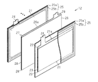
- the electrode assembly 12 includes an electrode storage separator 25 in which the positive electrode 21 is stored, and a negative electrode 26 having a polarity different from that of the positive electrode 21.
- the positive electrode 21 corresponds to the first electrode
- the negative electrode 26 corresponds to the second electrode.
- the electrode assembly 12 has a layered structure in which a plurality of electrode storage separators 25 and a plurality of negative electrodes 26 are alternately stacked.
- the electrode assembly 12 has a configuration in which the negative electrodes 26 are arranged at both ends in the stacking direction, and the number of the negative electrodes 26 is one more than the number of the electrode storage separators 25.
- the positive electrode 21 has a square sheet-like positive electrode metal foil (for example, aluminum foil) 22 and a positive electrode active material layer 23 containing a positive electrode active material on both surfaces of the positive electrode metal foil 22.
- the positive electrode 21 includes a positive electrode tab 24 having a shape protruding from the edge 21a.
- the positive electrode tab 24 of each positive electrode 21 is electrically connected to the positive electrode terminal 16.
- the negative electrode 26 has a square sheet-like negative electrode metal foil (for example, copper foil) 27 and a negative electrode active material layer 28 containing a negative electrode active material on both surfaces of the negative electrode metal foil 27.
- the negative electrode 26 includes a negative electrode tab 29 having a shape protruding from the end edge 26a.
- the negative electrode tab 29 of each negative electrode 26 is electrically connected to the negative electrode terminal 17.
- the separator portion of the electrode storage separator 25 is composed of a square sheet-like first separator member 25a and a square sheet-like second separator member 25b facing each other, and the four sides of the first separator member 25a and the second separator member 25b. The edges are welded together. Both the first separator member 25a and the second separator member 25b are microporous films. The first separator member 25 a and the second separator member 25 b have the same size and are slightly larger than the positive electrode 21.
- the manufacturing apparatus 30 includes a first manufacturing line 31 for manufacturing the electrode storage separator 25.
- the first production line 31 is a line for producing the positive electrode 21 and wrapping the positive electrode 21 with the first separator member 25a and the second separator member 25b to form the electrode housing separator 25.
- the manufacturing apparatus 30 includes a second manufacturing line 41 that manufactures the negative electrode 26 and a stacked portion 51 that stacks the electrode storage separator 25 and the negative electrode 26. Further, the manufacturing apparatus 30 includes the first manufacturing line 30.
- a control unit 61 that controls driving of the production line 31 and the second production line 41.
- the first manufacturing line 31 includes a first coating unit 32, a first coating buffer unit 33, a first punching unit 34 and a separator wrapping unit 35 as a first manufacturing unit, and a first buffer unit 36. .
- the punching process by the first punching part 34 is performed, and the positive electrode 21 is manufactured. Further, in the first production line 31, a step of wrapping the positive electrode 21 with the first separator member 25a and the second separator member 25b by the separator wrap 35 is performed.
- the first coating part 32 is a facility for producing a precursor of the positive electrode that becomes the positive electrode active material layer 23 on both sides of the long metal foil that becomes the positive electrode metal foil 22.
- the active material mixture of a positive electrode is coated with the coating machine on one surface of the longitudinal direction of long metal foil. Then, in the 1st coating part 32, an active material mixture is dried and pressed. Furthermore, after the active material mixture of the positive electrode is applied to the other surface of the long metal foil, the active material mixture is dried and pressed. And the precursor of an active material layer is formed on both surfaces of a long metal foil, and the electrode material 19a is manufactured.
- the coating method of an active material mixture may be any coating method such as a slit die method or a gravure roll method.
- the electrode material 19 a manufactured in the first coating unit 32 performs the next process of the first coating unit 32. This is a facility for delaying the timing sent to one punching section 34.
- the electrode material 19a manufactured by the first coating unit 32 is fed toward the first coating buffer unit 33 by the feed roller 33b.
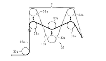
- the first coating buffer unit 33 includes a plurality of tension rollers 33a on the downstream side of the feed roller 33b in the conveying direction of the electrode material 19a, and the plurality of tension rollers 33a are arranged in parallel along the conveying direction of the electrode material 19a. ing.
- the plurality of tension rollers 33a are arranged in parallel so as to alternately contact the upper surface and the lower surface of the electrode material 19a, apply tension to the electrode material 19a, and restrict the electrode material 19a from being loosely conveyed.
- Each tension roller 33a is configured to be movable in the vertical direction.
- the region from the most upstream tension roller 33a in the transport direction to the most downstream tension roller 33a is defined as a transport region C for the electrode material 19a.
- the tension roller 33a contacting the lower surface of the electrode material 19a pushes up the electrode material 19a, or the tension roller contacting the upper surface of the electrode material 19a.
- the path length of the electrode material 19a in the transport region C can be adjusted by controlling the number of tension rollers 33a that push up or down the electrode material 19a and the amount of movement of the moved tension roller 33a. .
- the first punched portion 34 of the first production line 31 is a facility for punching the electrode material 19 a along the shape of the positive electrode 21.
- the separator wrapping part 35 is equipment for manufacturing the electrode storage separator 25 by wrapping the positive electrode 21 manufactured by the first punching part 34 with the first separator member 25a and the second separator member 25b.
- the first buffer unit 36 is a facility that enables accumulation of the electrode storage separator 25. The first buffer unit 36 can grasp the number of electrode storage separators 25 existing as stock and output the stock amount as a detection signal.
- the first production line 31 includes a first disposal line 37, and the first disposal line 37 is connected to the first discharge unit 37a.
- the first discard line 37 is arranged to be branched from the conveyance path located between the separator wrapping part 35 and the first buffer part 36.
- the first production line 31 includes a guide member 38 that guides the electrode storage separator 25 so that the electrode storage separator 25 flows through the first disposal line 37.
- the second manufacturing line 41 includes a second coating part 42, a second coating buffer part 43, a second punching part 44 as a second manufacturing part, and a second buffer part 46.
- the punching process by the second punching part 44 is performed.
- the second coating part 42 has the same configuration as the first coating part 32, detailed description thereof is omitted.
- the first coating unit 32 if “first” is read as “second” and “positive electrode” is read as “negative electrode”, the second coating unit 42 is described.
- the 2nd coating buffer part 43 is the same structure as the 1st coating buffer part 33, the detailed description is abbreviate
- the second punching portion 44 is a facility for punching the electrode material 19 a along the shape of the negative electrode 26.
- the second buffer unit 46 is a facility that can store the negative electrode 26.
- the second buffer unit 46 can grasp the number of negative electrodes 26 existing as stock and output the stock quantity as a detection signal.
- the second production line 41 includes a second disposal line 47, and the second disposal line 47 is connected to the second discharge unit 47a.
- the second discard line 47 is disposed on a conveyance path located between the second punching unit 44 and the second buffer unit 46.
- the second manufacturing line 41 includes a guide member 48 that guides the negative electrode 26 so that the negative electrode 26 flows through the second disposal line 47.
- the laminated portion 51 is for manufacturing the electrode assembly 12 by alternately laminating the electrode storage separator 25 accumulated in the first buffer portion 36 and the negative electrode 26 accumulated in the second buffer portion 46.
- the control unit 61 is signal-connected to the first coating buffer unit 33, the first punching unit 34, the separator wrapping unit 35, the guide member 38, and the first buffer unit 36 in the first production line 31.
- the control unit 61 is signal-connected to the second coating buffer unit 43, the second punching unit 44, the guide member 48, and the second buffer unit 46 in the second production line 41.
- the control unit 61 can output an instruction to move the tension roller 33a up and down to the first coating buffer unit 33 and the second coating buffer unit 43. When the instruction is output, the path of the electrode material 19a is output. The length is adjusted. Further, the control unit 61 can output an instruction to stop the punching of the electrode material 19a to the first punching unit 34 and the second punching unit 44. When this instruction is output, the driving of the punched portions 34 and 44 is stopped, and the production of the positive electrode 21 and the negative electrode 26 is stopped.
- the control unit 61 can output an instruction to the separator wrapping unit 35 to stop the operation of wrapping the positive electrode 21 with the first separator member 25a and the second separator member 25b.
- this instruction is output, the driving of the separator wrap 35 is stopped, and the manufacture of the electrode storage separator 25 is stopped.
- the buffer units 36 and 46 detect the stock quantity. Each of the buffer units 36 and 46 can output a signal including the detected inventory quantity to the control unit 61. When the signal including the inventory quantity is input, the control unit 61 grasps the inventory quantity of each of the buffer units 36 and 46. To do.
- the control unit 61 can output an instruction for accumulating the electrode storage separator 25 to the first buffer unit 36, and can output an instruction for accumulating the negative electrode 26 to the second buffer unit 46.
- the control unit 61 can output an instruction to flow the electrode storage separator 25 toward the stacking unit 51 to the first buffer unit 36, and the negative electrode 26 to the second buffer unit 46. An instruction to flow toward the stacking unit 51 can be output.
- a plurality of threshold values relating to inventory are set in order to control the driving of the manufacturing apparatus 30, and a reserve inventory amount, a main inventory amount, and a minimum inventory amount are set as the plurality of threshold values. And are set.
- the main inventory amount is a preferable inventory amount to be secured in each of the buffer units 36 and 46, and does not cause an overflow or out of stock of the electrodes in each of the buffer units 36 and 46. This is the amount of inventory that must be secured for stable production.
- the main stock quantity is a value that falls within a predetermined range. In the present embodiment, the main stock quantity is set to 10 to 25 sheets.
- the reserve stock amount is the maximum value of the stock that can be accumulated in each buffer unit 36, 46. When the reserve stock amount is exceeded, each electrode overflows from each buffer unit 36, 46.
- the reserve stock quantity is set to 30 sheets.
- the reserve stock quantity is set with a margin of plural sheets (5 sheets) to the upper limit value (25 sheets) in the range of the main stock quantity. Accordingly, each electrode can be stored in each of the buffer units 36 and 46 from the time when the upper limit value of the main stock quantity is exceeded until the time when the reserve stock quantity is reached. 36 and 46 are close to overflow.
- the minimum stock amount is the minimum stock value of each buffer unit 36, 46. When the minimum stock amount falls below the minimum stock amount, each buffer unit 36, 46 runs out of stock.
- the minimum stock quantity is set to one.
- the minimum stock quantity is set to a value obtained by providing a plurality of sheets with a lower limit value (10 sheets) in the range of the main stock quantity. Accordingly, although there is still stock in each of the buffer units 36 and 46 from the time when the value falls below the lower limit value of the main stock amount to the time when the minimum stock amount is reached, the buffer units 36 and 46 become smaller as the lower limit value of the main stock amount is reached. Is approaching out of stock.
- the control unit 61 outputs various instructions according to various stock quantities.
- the control of the control unit 61 will be described with reference to FIG. 5, with the first punching part 34 and the separator wrapping part 35 as the first manufacturing part and the second punching part 44 as the second manufacturing part.
- the stock in the first buffer unit 36 in the first production line 31 varies
- the stock in the second buffer unit 46 in the second production line 41 is within the range of the main stock quantity. The description will be made on the assumption of the state.
- the symbol “ ⁇ ” means that the corresponding manufacturing process is continued, and the symbol “X” means that the corresponding manufacturing process is not stopped or performed.
- the control unit 61 instructs the first manufacturing unit of the first manufacturing line 31 and the second manufacturing unit of the second manufacturing line 41 to manufacture each electrode.
- the buffer units 36 and 46 detect inventory and output a detection signal to the control unit 61.
- step S1 determines whether or not the stock in the first buffer unit 36 exceeds the reserve stock amount (30 sheets) that is the maximum value (step S1). If the determination in step S1 is affirmative (YES in step S1), the electrode storage separator 25 has overflowed from the first buffer unit 36. The storage separator 25 cannot be stored.
- the control unit 61 In order to stop the manufacturing in the first manufacturing unit, the control unit 61 outputs an instruction to stop the work to the first punching unit 34 and the separator wrapping unit 35 (first Manufacturing department). Then, the punching operation of the positive electrode 21 and the operation of wrapping the positive electrode 21 with the first separator member 25a and the second separator member 25b are stopped. As a result, further production of the electrode storage separator 25 is stopped.
- the control unit 61 continues to output a manufacturing instruction to the second punching unit 44 (second manufacturing unit). ⁇ ).
- the control unit 61 includes the electrode storing separator 25 already completed in the separator wrapping unit 35 before the production is stopped.
- An instruction to stop the supply to the first buffer unit 36 is output to the guide member 38 (accumulation ⁇ ).
- the guide member 38 causes the electrode storage separator 25 from the separator wrap 35 to the first buffer 36 to flow from the first manufacturing line 31 to the first waste line 37 and is discharged to the first discharge part 37a.
- the electrode storage separator 25 is not accumulated in the first buffer unit 36, and the inventory does not increase.
- the control unit 61 outputs an instruction to flow the electrode storage separator 25 to the stacking unit 51 to the first buffer unit 36 (lamination flow ⁇ ). Then, the electrode storage separator 25 flows from the first buffer unit 36 toward the stacking unit 51, the stock of the first buffer unit 36 decreases, the overflow state is eliminated, and the stock is the main stock amount. It approaches the upper limit.
- the control unit 61 flows the negative electrode 26 to the stacked unit 51 with respect to the second buffer unit 46. Instruction to output (lamination flow ⁇ ). As a result, the electrode storage separator 25 and the negative electrode 26 are stacked in the stacked portion 51.
- step S1 determines whether the stock in the first buffer unit 36 exceeds the upper limit value of the main stock amount range. If the determination in step S2 is affirmative (YES in step S2), the electrode storage separator 25 has not overflowed in the first buffer unit 36, and therefore the electrode storage separator 25 can be accumulated, but is in a state close to overflow. .
- the production in the first production unit is stopped.
- the control unit 61 outputs an instruction to stop the work to the first punching unit 34 and the separator wrapping unit 35 (first manufacturing unit ⁇ ). Then, the punching operation of the positive electrode 21 and the operation of wrapping the positive electrode 21 with the first separator member 25a and the second separator member 25b are stopped. As a result, further production of the electrode storage separator 25 is stopped, and the inventory does not increase.
- the control unit 61 continues to output a manufacturing instruction to the second punching unit 44 (second manufacturing unit). ⁇ ).
- the control unit 61 completes the electrode storage separator 25 completed in the separator wrapping unit 35 before the production of the electrode storage separator 25 is stopped. Is supplied to the guide member 38 (accumulation ⁇ ). At this time, the guide member 38 does not flow the electrode storage separator 25 from the separator wrapping part 35 toward the first buffer part 36 to the first disposal line 37. Therefore, the electrode storage separator 25 is supplied from the first production line 31 to the first buffer unit 36, and the electrode storage separator 25 is accumulated in the first buffer unit 36.
- the control unit 61 instructs the first buffer unit 36 to flow the electrode storage separator 25 to the stacking unit 51. Is output (lamination flow ⁇ ). Then, the electrode storage separator 25 flows from the first buffer unit 36 toward the stacking unit 51, and the inventory of the first buffer unit 36 decreases, approaching the upper limit value of the main inventory amount.
- the control unit 61 flows the negative electrode 26 to the stacked unit 51 with respect to the second buffer unit 46. Instruction to output (lamination flow ⁇ ). As a result, the electrode storage separator 25 and the negative electrode 26 are stacked in the stacked portion 51.
- step S3 the control unit 61 determines whether or not the stock of the first buffer unit 36 is within the range of the main stock amount. If the determination in step S3 is affirmative (YES in step S3), the inventory of the first buffer unit 36 is normal.
- the control unit 61 continues the manufacture of the electrode storage separator 25 in the first manufacturing unit in order to maintain the stock in the first buffer unit 36 within the range of the main stock amount. Therefore, the control unit 61 continuously outputs a manufacturing instruction to the first punching unit 34 and the separator wrapping unit 35 (first manufacturing unit ⁇ ). Then, the punching operation of the positive electrode 21 and the operation of wrapping the positive electrode 21 with the first separator member 25a and the second separator member 25b are performed. As a result, the electrode storage separator 25 is manufactured.
- the control unit 61 continues to output a manufacturing instruction to the second punching unit 44 (second manufacturing unit). ⁇ ).
- the control unit 61 instructs to supply the electrode storage separator 25 completed in the separator wrapping unit 35 to the first buffer unit 36. Is output to the guide member 38 (accumulation ⁇ ).
- the guide member 38 does not flow the electrode storage separator 25 from the separator wrapping portion 35 toward the first buffer portion 36 to the first disposal line 37. Therefore, the electrode storage separator 25 is supplied from the first production line 31 to the first buffer unit 36, the electrode storage separator 25 is accumulated, and the stock of the first buffer unit 36 is within the range of the main stock amount. Maintained.
- the control unit 61 sends the electrode storage separator to the stacking unit 51 with respect to the first buffer unit 36.
- indication which makes 25 flow is output (lamination
- the electrode storage separator 25 flows from the first buffer unit 36 toward the stacked unit 51.
- the control unit 61 flows the negative electrode 26 to the stacked unit 51 with respect to the second buffer unit 46. Instruction to output (lamination flow ⁇ ). As a result, the electrode storage separator 25 and the negative electrode 26 are stacked in the stacked portion 51.
- step S3 if negative in step S3 (NO in step S3), the process proceeds to step S4.
- the case of NO in step S3 is a case where the stock in the first buffer unit 36 falls below the lower limit (10 sheets) of the main stock quantity that is a predetermined number.
- the control unit 61 determines whether the stock in the first buffer unit 36 is equal to or greater than the minimum stock amount (one sheet). If the determination in step S4 is affirmative (YES in step S4), in the first buffer unit 36, the electrode storage separator 25 is below the lower limit (10 sheets) of the main inventory quantity and is equal to or greater than the minimum inventory quantity (1 sheet). The stock is in the state of 1 to 9 sheets, which is almost out of stock. Note that “above the minimum inventory quantity” includes one minimum inventory quantity.
- control unit 61 outputs an instruction for causing the first punching unit 34 and the separator wrapping unit 35 to work in order to increase the stock in the first buffer unit 36 (first manufacturing unit ⁇ ). Then, the punching operation of the positive electrode 21 and the operation of wrapping the positive electrode 21 with the first separator member 25a and the second separator member 25b are performed. As a result, the electrode storage separator 25 is manufactured, the stock of the first buffer unit 36 is increased, and the stock of both the buffer units 36 and 46 is balanced.
- step S4 determines whether the stock in the second buffer unit 46 is equal to or greater than the lower limit (10 sheets) of the main stock amount range.
- an instruction to stop the work is output to the second punching unit 44 ( Second production department x). Thereby, the increase in inventory in the second buffer unit 46 is stopped.
- the second punching unit 44 does not output an instruction to stop the work, and the work is continued. Let As a result, the stock in the second buffer unit 46 is maintained in a state close to the lower limit value of the main stock amount.
- the control unit 61 instructs to supply the electrode storage separator 25 completed in the separator wrapping unit 35 to the first buffer unit 36. Is output to the guide member 38 (accumulation ⁇ ). The guide member 38 does not flow the electrode storage separator 25 from the separator wrapping portion 35 toward the first buffer portion 36 to the first disposal line 37. For this reason, the electrode storage separator 25 is supplied from the first production line 31 to the first buffer unit 36, and the electrode storage separator 25 is accumulated, increasing the inventory.
- the control unit 61 outputs an instruction to flow the electrode storage separator 25 to the stacking unit 51 to the first buffer unit 36. (Laminate flow ⁇ ). Then, the electrode storage separator 25 flows from the first buffer unit 36 toward the stacked unit 51. If the stock of the second buffer unit 46 is equal to or greater than the minimum stock amount, the control unit 61 outputs an instruction to flow the negative electrode 26 to the stacked unit 51 to the second buffer unit 46 (laminated flow ⁇ ). As a result, the electrode storage separator 25 and the negative electrode 26 are stacked in the stacked portion 51.
- step S4 if the answer is negative in step S4 (NO in step S4), the first buffer unit 36 is out of stock. For this reason, the control unit 61 causes the electrode storage separator 25 to be manufactured in order to increase the stock in the first buffer unit 36.
- the control unit 61 outputs an instruction for causing the first punching unit 34 and the separator wrapping unit 35 to perform an operation (first manufacturing unit ⁇ ). Then, the punching operation of the positive electrode 21 and the operation of wrapping the positive electrode 21 with the first separator member 25a and the second separator member 25b are performed. As a result, the electrode storage separator 25 is manufactured.
- step S4 if the stock in the second buffer unit 46 is equal to or greater than the lower limit (10 sheets) of the main stock amount range, an instruction to stop the work is output to the second punching unit 44 (Second manufacturing section x). Thereby, the increase in the inventory of the second buffer unit 46 is stopped.
- the second punching unit 44 does not output an instruction to stop the operation, and the negative electrode 26 Continue manufacturing.
- the stock in the second buffer unit 46 is maintained in a state close to the lower limit value of the main stock amount.
- the electrode storage separator 25 is accumulated in the first buffer unit 36, the stock increases, and the stock in the second buffer unit 46 is maintained at the lower limit value of the main stock amount. Balance of inventory.
- the control unit 61 instructs to supply the electrode storage separator 25 completed in the separator wrapping unit 35 to the first buffer unit 36. Is output to the guide member 38 (accumulation ⁇ ). The guide member 38 does not flow the electrode storage separator 25 from the separator wrapping portion 35 toward the first buffer portion 36 to the first disposal line 37. For this reason, the electrode storage separator 25 is supplied from the first production line 31 to the first buffer unit 36, and the electrode storage separator 25 is accumulated.
- the control unit 61 outputs an instruction to stop the flow of the electrode storage separator 25 to the stacking unit 51 to the first buffer unit 36 (stacking). Flow x). Then, the flow of the electrode storage separator 25 from the first buffer unit 36 toward the stacked unit 51 is stopped. Therefore, the electrode storage separator 25 is accumulated in the first buffer unit 36, and the stock approaches the main stock amount.
- step S1 and step S2 punching by the first punching unit 34 is stopped.
- the control unit 61 drives the first coating buffer unit 33 and moves the tension roller 33a. Then, the path length of the electrode material 19a transported in the transport region C becomes longer than the shortest case, and the coating operation does not have to be stopped while the punching is stopped.
- the buffer units 36 and 46 are provided in the production lines 31 and 41, respectively.
- the control unit 61 continues the manufacture of the electrode storage separator 25 by the first manufacturing unit, while maintaining the negative electrode by the second manufacturing unit.
- the production of 26 is stopped.
- the second buffer unit 46 on the second manufacturing unit side the inventory of the negative electrode 26 does not increase.
- the stock in the first buffer unit 36 on the first manufacturing unit side increases. For this reason, the first buffer unit 36 and the second buffer unit 46 balance both stocks.
- the stacking process of the electrode assembly 12 is performed in a state where the inventory of the electrode storage separator 25 and the inventory of the negative electrode 26 are balanced, and the manufacturing process of the electrode assembly 12 in a state where both the inventory is unbalanced. It is not necessary to control the decrease in productivity of the electrode assembly 12.
- a lower limit is set in the range of the main inventory amount in each of the buffer units 36 and 46. And even if it is a case where each buffer part 36 and 46 has stock, if a stock falls below the lower limit of the main stock quantity, the control part 61 will not stop manufacture by the one manufacturing part which fell below the lower limit. . Therefore, it is possible to increase the stock of the buffer unit before the out of stock occurs in one manufacturing unit that is below the lower limit of the main stock amount.
- the upper limit value of the main inventory amount range is set in each of the buffer units 36 and 46. And when the stock of each buffer part 36 and 46 exceeds the upper limit of the main stock quantity, the control part 61 stops manufacture of one manufacturing part which exceeded the upper limit. For this reason, the increase in inventory can be stopped before each buffer part 36 and 46 overflows.
- control part 61 makes an electrode flow from each buffer part 36 and 46, and makes it laminate
- the reserve inventory amount is set as the maximum inventory value in each of the buffer units 36 and 46. Then, when the stock of the buffer units 36 and 46 exceeds the reserve stock quantity, the control unit 61 stops the production of the electrode by the production department that exceeds the reserve stock quantity. For this reason, further manufacture of the electrodes is stopped, and further overflow of the electrodes in the buffer portions 36 and 46 is avoided.
- the reserve inventory amount is set as the maximum inventory value in each of the buffer units 36 and 46.
- the control unit 61 drives the guide member 38. Then, by driving the guide member 38, the electrodes manufactured before the timing of the production stop are caused to flow through the disposal lines 37 and 47 so that the stock of the buffer units 36 and 46 is not increased. Therefore, further overflow of the electrodes in the buffer units 36 and 46 is avoided.
- each production line 31, 41 a laminated portion 51 is disposed downstream of each buffer portion 36, 46.
- the stock of the buffer units 36 and 46 is maintained within the range of the main stock amount by the control of each manufacturing unit by the control unit 61, and the stock balance between the negative electrode 26 and the electrode storage separator 25 is achieved. Therefore, the out-of-stock situation does not occur, and in the stacking unit 51, the electrode storage separator 25 and the negative electrode 26 required for manufacturing the electrode assembly 12 are stacked, resulting in a decrease in productivity of the electrode assembly 12. It is suppressed.
- the manufacturing apparatus 30 includes a control unit 61, and the control unit 61 is signal-connected to each facility of the manufacturing lines 31 and 41. And since the control part 61 controls the drive of each installation collectively, the stock adjustment in each buffer part 36 and 46 can be performed through the whole manufacturing apparatus 30.
- FIG. 1 A control unit 61, and the control unit 61 is signal-connected to each facility of the manufacturing lines 31 and 41. And since the control part 61 controls the drive of each installation collectively, the stock adjustment in each buffer part 36 and 46 can be performed through the whole manufacturing apparatus 30.
- the first production line 31 includes a first punching portion 34, a separator wrapping portion 35, and a first buffer portion 36
- the second manufacturing line 41 is a second punching portion. 44 and the second buffer unit 46 may be used.
- the first buffer unit 36 and the second buffer unit 46 are signal-connected to each other, and the first buffer unit 36 is signal-connected to the first punching unit 34 and the separator wrapping unit 35.
- the second buffer unit 46 and the second punching unit 44 are signal-connected.
- the first buffer unit 36 outputs an instruction to the first punching unit 34 and the separator wrapping unit 35, and the second buffer The unit 46 may output an instruction to the second punching unit 44.
- the host control unit 61 may not be provided as in the embodiment, and the stock adjustment may be performed using the buffer units 36 and 46 as control units.
- step S3 of FIG. 5 the first buffer unit 36 determines whether or not the stock of the buffer unit 36 is within the range of the main stock amount. If the determination in step S3 is affirmative (YES in step S3), the inventory of the first buffer unit 36 is normal.
- the first buffer unit 36 continues to manufacture the electrode storage separator 25 in the first manufacturing unit in order to maintain its inventory. Therefore, the first buffer unit 36 continuously outputs manufacturing instructions to the first punching unit 34 and the separator wrapping unit 35 (first manufacturing unit ⁇ ). As a result, the electrode storage separator 25 is manufactured.
- the second buffer unit 46 since the stock of the second buffer unit 46 is within the range of the main stock amount, the second buffer unit 46 continuously outputs the manufacturing instruction to the second punching unit 44 (second Production department ⁇ ). As a result, the inventory of the first buffer unit 36 and the inventory of the second buffer unit 46 are balanced.
- step S ⁇ b> 4 the first buffer unit 36 determines whether or not the minimum stock quantity is exceeded. If the determination in step S4 is affirmative (YES in step S4), in the first buffer unit 36, the electrode storage separator 25 is below the lower limit value of the main inventory quantity and is equal to or greater than the minimum inventory quantity (one sheet), and the inventory is 1 The number of sheets is 9 to 9, which is almost out of stock.
- the first buffer unit 36 outputs an instruction for causing the first punching unit 34 and the separator wrapping unit 35 to work in order to increase the stock in the first buffer unit 36 (first manufacturing unit ⁇ ). . Then, the electrode storage separator 25 is manufactured, the stock of the first buffer unit 36 increases, and the stock of the first buffer unit 36 and the stock of the second buffer unit 46 are balanced.
- step S4 If the determination in step S4 is affirmative (YES in step S4), the second buffer unit 46 is in a state where it can output an instruction to stop the operation of the second punching unit 44. If the result in step S4 is affirmative, if the main stock amount of the second buffer unit 46 is equal to or greater than the lower limit value (10 sheets) of the range, the first buffer unit 36 The second punching unit 44 outputs an instruction to stop the work. Then, the second buffer unit 46 outputs an instruction to stop the work to the second punching unit 44 (second manufacturing unit ⁇ ). Thereby, the increase in inventory in the second buffer unit 46 is stopped.
- the first buffer unit 36 has a second punching unit with respect to the second buffer unit 46. 44 does not output an instruction to stop the work. For this reason, the second buffer unit 46 causes the second punching unit 44 to continue the operation. As a result, the inventory of the second buffer unit 46 is maintained close to the lower limit value of the main inventory amount, and the inventory of the first buffer unit 36 and the inventory of the second buffer unit 46 are balanced.
- the positive electrode 21 does not have to be wrapped with a bag-shaped separator.
- one sheet-like separator is interposed between the positive electrode 21 and the negative electrode 26.
- the separator wrapping portion 35 of the first manufacturing line 31 is eliminated, while a separator manufacturing line 65 is added.
- the separator production line 65 includes a separator punching unit 66 that punches and manufactures a separator, and a separator buffer unit 67 that stores the manufactured separator.
- first buffer unit 36 and the second buffer unit 46 are signal-connected to each other as in the embodiment of FIG.
- first buffer unit 36 and the separator buffer unit 67 are signal-connected so as to be able to input and output signals
- the second buffer unit 46 and the separator buffer unit 67 are connected so as to be able to input and output signals.
- separator buffer unit 67 and the separator punching unit 66 are signal-connected, and the separator buffer unit 67 is connected to the separator punching unit 66 so as to be instructed.
- the first buffer unit 36 outputs an instruction to the first punching unit 34
- the second buffer unit 46 outputs an instruction to the second punching portion 44.
- the separator buffer unit 67 outputs an instruction to the separator punching unit 66 based on the stock of the separator buffer unit 67.
- the first buffer 36 outputs an instruction to the first punching unit 34
- the second buffer 46 outputs an instruction to the second punching unit 44. Also good.
- the first buffer unit 36 and the second buffer unit 46 instruct to stop manufacturing electrodes by the punching units 34 and 44. Further, the separator buffer unit 67 outputs a manufacturing continuation instruction to the separator punching unit 66.
- the present embodiment it is possible to suppress a decrease in productivity of the electrode assembly 12 while balancing each stock even in a configuration including three or more buffer units as well as two buffer units. it can.
- the number of separators used in the stacking process when manufacturing one electrode assembly 12 is the number obtained by subtracting 1 from the total number of positive electrodes 21 and negative electrodes 26.
- the threshold value related to the stock set in the separator buffer unit 67 is the stock of the first buffer unit 36 or the second buffer unit 46. You may make it different from the threshold value regarding.
- the manufacturing apparatus 30 may not include the stacking unit 51.
- the electrode assembly 12 may be manufactured by laminating the electrode storage separator 25 accumulated in the first buffer portion 36 and the negative electrode 26 accumulated in the second buffer portion 46 at different locations. Good.
- each production line 31, 41 the disposal lines 37, 47 and the guide members 38, 48 may be omitted. In this case, when an electrode overflows in each buffer part 36 and 46, it is preferable to discard the overflowed electrode by manual work or an arbitrary method.
- step S2 even if the stock of each buffer unit 36, 46 exceeds the upper limit of the main inventory range (YES in step S2), manufacture of electrodes by the manufacturing unit that exceeds the upper limit May be stopped and production may be continued. In this case, the stacking flow from the buffer units 36 and 46 to the stacking unit 51 may be stopped.
- step S4 even if the stock of each buffer unit 36, 46 is below the lower limit value of the main inventory range (YES in step S4), the electrode is manufactured by the manufacturing unit below the lower limit value. May be stopped. In this case, the stacking flow from the buffer units 36 and 46 to the stacking unit 51 may be stopped.
- the electrode manufacturing section does not have to be a facility for punching the electrode material along the shape of the electrode as in the first punched portion 34 and the second punched portion 44.
- the electrode is manufactured by a laser cut method or a die cut method. May be.
- Each electrode may have an active material layer on one side of a metal foil.
- the active material mixture is applied only to one longitudinal surface of the long metal foil, the active material mixture is dried and pressed to produce the electrode material 19a. Is done.
- the positive electrode 21 may be used as the second electrode and the negative electrode 26 may be used as the first electrode.
- the punched portion and the separator wrapping portion where the positive electrode 21 is punched from the electrode material 19a become the second manufacturing portion.
- a punched portion in which the electrode 26 is punched from the electrode material 19a is a first manufacturing portion.
- the electrodes overflowed in the buffer units 36 and 46 are discarded.
- the overflowed electrodes may be collected and reused in another place without being discarded.
- the second discard line 47 may be joined to the second buffer unit 46 and reused.
- control unit 61 determines whether or not the stock of the first buffer unit 36 has fallen below a predetermined number. Instead of this, the control unit 61 may determine whether or not the stock of any of the buffer units 36 and 46 is zero.
- control unit 61 stops the operation of the second punching unit 44 when the stock in the first buffer unit 36 falls below a predetermined number (YES in Step S4).
- control unit 61 is not limited to this, and the control unit 61 reduces the difference between the number of stocks in the first buffer unit 36 and the number of stocks in the second buffer unit 46 so that the first manufacturing unit and the second manufacturing unit are manufactured. It may be configured to adjust the production rate of at least one of the parts.
- the control unit 61 maintains the production speed of the first production line 31 including the first punching unit 34 while maintaining the second production rate.
- the manufacturing speed of the second manufacturing line 41 including the punching portion 44 may be reduced.
- the control unit 61 causes the production rate of the second production line 41 to be lower than the production rate of the first production line 31.
- the control unit 61 increases the manufacturing speed of the first manufacturing line 31 relative to the manufacturing speed of the second manufacturing line 41.
- the difference between the number of stocks in the first buffer unit 36 and the number of stocks in the second buffer unit 46 is reduced without stopping either the first production line 31 or the second production line 41. can do.
- the control unit 61 maintains the production speed of the second production line 41 including the second punching unit 44 when the stock of the first buffer unit 36 falls below a predetermined number.
- the production speed of the first production line 31 including the first punched portion 34 may be increased.
- the control unit 61 may increase the manufacturing speed of the first manufacturing line 31 relative to the manufacturing speed of the second manufacturing line 41.
- control unit 61 includes a second punching portion 44.
- the production speed of the first production line 31 including the first punched portion 34 is increased while maintaining the production speed of the production line 41.
- the inventory of the first buffer unit 36 is relatively increased as compared with the inventory of the second buffer unit 46.
- the difference between the number of stocks in the first buffer unit 36 and the number of stocks in the second buffer unit 46 without stopping either the first production line 31 or the second production line 41. Can be reduced.
- the symbol “ ⁇ ” means to increase the manufacturing speed of the corresponding manufacturing process.
- the manufacturing apparatus is for manufacturing the electrode assembly 12 having the electrode storage separator 25.
- the present invention may be embodied in an apparatus for manufacturing an electrode assembly that does not use the electrode storage separator 25. In that case, the separator wrapping part 35 of the first production line 31 of FIG. 3 is omitted.
- a positive electrode that is not housed in the electrode housing separator is used to manufacture the electrode assembly.
- a positive electrode, a separator, and a negative electrode are laminated.
- first buffer unit 36 and the second buffer unit 46 are separate facilities from the stacked unit 51.
- first buffer unit 36 and the second buffer 46 may be a facility integrated with the stacked unit 51.
- a first manufacturing section for manufacturing a first electrode A first buffer unit capable of storing the first electrode manufactured by the first manufacturing unit; A second manufacturing section for manufacturing a second electrode having a polarity different from that of the first electrode; A second buffer unit enabling accumulation of the second electrode manufactured in the second manufacturing unit; A control unit that outputs an instruction according to the inventory of the first buffer unit and the inventory of the second buffer unit, The first and second manufacturing units are arranged in parallel so that the manufacturing speed can be adjusted independently, When the inventory of one electrode stored in the first buffer unit or the second buffer unit falls below a predetermined number, the control unit determines the number of inventory in the first buffer unit and the first buffer unit.
- An apparatus for manufacturing an electrode assembly that adjusts a manufacturing speed of at least one of the first manufacturing unit and the second manufacturing unit so that a difference from the number of stocks of the two buffer units is small.
Landscapes
- Engineering & Computer Science (AREA)
- Manufacturing & Machinery (AREA)
- Chemical & Material Sciences (AREA)
- Chemical Kinetics & Catalysis (AREA)
- Electrochemistry (AREA)
- General Chemical & Material Sciences (AREA)
- Secondary Cells (AREA)
- Electric Double-Layer Capacitors Or The Like (AREA)
Abstract
電極組立体の製造装置は、第1の製造部と、第1の電極の蓄積を可能とした第1のバッファ部と、第2の製造部と、第2の電極の蓄積を可能とする第2のバッファ部と、第1のバッファ部の在庫、及び第2のバッファ部の在庫に応じた指示を出力する制御部とを有する。第1のバッファ部又は第2のバッファ部に蓄積された一方の電極の在庫が所定枚数を下回った場合には、制御部は、他方の電極の製造部による電極の製造を停止又は製造速度を低下しつつ、前記一方の電極の製造部による電極の製造を継続する。
Description
本発明は、電極組立体の製造装置、及び電極組立体の製造方法に関する。
二次電池やキャパシタのような蓄電装置は再充電が可能であり、繰り返し使用することができるため電源として広く利用されている。例えば、リチウムイオン二次電池では、活物質層を有するシート状の正極電極及び負極電極が、間にセパレータが介在する状態で層をなすように積層された電極組立体がケースに収容されている。シート状の正極電極及び負極電極は、金属箔の両面に活物質層を有する。
二次電池の製造は、まず、正極電極及び負極電極を製造し、その後、それら電極を積層して電極組立体を製造し、電極組立体をケースに収容して行われる。二次電池の製造のうち、電極組立体を製造する装置としては、例えば、特許文献1に開示の積層体(電極組立体)の作製装置が挙げられる。特許文献1に開示の作製装置は、フープ状に巻き取られたシート状体を短冊状に切断して供給する供給機構と、供給機構の下方に位置し、供給機構から供給された短冊状のシート状体を、重力を利用して所定の位置に落下移動させる落下移動手段と、を備える。さらに、作製装置は、案内積層手段を備え、この案内積層手段は、落下移動手段の排出部の下方である所定の位置に配置され、排出部から排出されたシート状体を順次所定の配置に案内して積層させる。
ところで、リチウムイオン二次電池やニッケル水素二次電池の電池容量は正極電極によって規制されるように設計されている。例えば、リチウムイオン二次電池では、電極組立体を構成する負極電極の枚数が、正極電極の枚数より1枚多く、電極組立体の製造工程(積層工程)で使用される正極電極の枚数と、負極電極の枚数は一致しない。
そして、リチウムイオン二次電池の積層工程は、負極電極及び正極電極の在庫を予め確保して行う場合が多い。しかし、負極電極の方が正極電極より使用枚数が多いことから、積層工程中に、負極電極の在庫が予め決められた所定枚数(下限値)を下回りやすい一方で、正極電極の在庫が負極電極の在庫より過剰になりやすく、正極電極の在庫と負極電極の在庫とがアンバランスになりやすい。そして、正極電極の在庫と負極電極の在庫とがアンバランスになりやすい中で、電極組立体を製造するには、その工程制御が非常に面倒であり、電極組立体の生産性が低下してしまう。
本発明の目的は、第1の電極と第2の電極とで在庫のバランスを取りながら電極組立体の生産性の低下を抑制することができる電極組立体の製造装置、及び電極組立体の製造方法を提供することにある。
上記目的を達成するための第1の態様の電極組立体の製造装置は、第1の電極を製造する第1の製造部と、前記第1の製造部で製造された前記第1の電極の蓄積を可能とした第1のバッファ部と、前記第1の電極と極性の異なる第2の電極を製造する第2の製造部と、前記第2の製造部で製造された前記第2の電極の蓄積を可能とする第2のバッファ部と、前記第1のバッファ部の在庫、及び前記第2のバッファ部の在庫に応じた指示を出力する制御部と、を有し、前記第1のバッファ部又は前記第2のバッファ部に蓄積された一方の電極の在庫が所定枚数を下回った場合には、前記制御部は、他方の電極の製造部による電極の製造を停止又は製造速度を低下しつつ、前記一方の電極の製造部による電極の製造を継続するように構成されていることを要旨とする。
これによれば、一方の電極の製造部において在庫が所定枚数を下回った場合には、その一方の電極の製造が継続される。また、他方の電極の製造部では、その他方の電極の製造が停止されるか又は製造速度が低下する。そして、他方の電極の製造が停止された場合には、その他方のバッファ部では電極の在庫は増えなくなる。他方の電極の製造速度が低下した場合には、その他方のバッファ部では電極の在庫の増加が抑制される。その一方で、一方の電極の製造は継続されることから、一方のバッファ部の在庫が増えていく。このため、第1の電極と第2の電極との間で在庫のバランスが取られる。このため、第1の電極及び第2の電極のうちの一方の電極の在庫が所定枚数を下回ることが抑制されるとともに、他方の電極の在庫が一方の電極の在庫より過剰になることが抑制される。その結果、過剰量の在庫を保管するための場所を確保する必要がなくなる。また、第1の電極と第2の電極の在庫のバランスを取りながら電極組立体を製造できるため、在庫がアンバランスな中で電極組立体の製造工程を制御する必要がなく、電極組立体の生産性が低下しない。
また、電極組立体の製造装置について、前記所定枚数はゼロより大きい値であるのが好ましい。
これによれば、バッファ部で在庫切れが発生する前に、在庫を増やす調整が行われ、いずれかのバッファ部で在庫切れが生じることを未然に回避することができる。
これによれば、バッファ部で在庫切れが発生する前に、在庫を増やす調整が行われ、いずれかのバッファ部で在庫切れが生じることを未然に回避することができる。
また、電極組立体の製造装置について、前記第1のバッファ部又は前記第2のバッファ部に蓄積された一方の電極の在庫がバッファ部で蓄積可能とする在庫の最大値に達する前に、前記一方の電極の製造部に対し前記制御部は電極の製造を停止又は製造速度を低下させてもよい。
これによれば、バッファ部から電極がオーバーフローする前に、在庫が増えることを回避できる。
また、電極組立体の製造装置について、前記第1のバッファ部又は前記第2のバッファ部に蓄積された一方の電極の在庫がバッファ部で蓄積可能とする在庫の最大値を越えた場合には、一方の製造部で製造された一方の電極をバッファ部への搬送経路から分岐させてもよい。
また、電極組立体の製造装置について、前記第1のバッファ部又は前記第2のバッファ部に蓄積された一方の電極の在庫がバッファ部で蓄積可能とする在庫の最大値を越えた場合には、一方の製造部で製造された一方の電極をバッファ部への搬送経路から分岐させてもよい。
これによれば、バッファ部で電極がオーバーフローすることを回避することができる。
また、電極組立体の製造装置について、前記第1のバッファ部に蓄積された前記第1の電極と、前記第2のバッファ部に蓄積された前記第2の電極とをそれぞれバッファ部から流動させて互いに絶縁した状態に積層する積層部を有する。
また、電極組立体の製造装置について、前記第1のバッファ部に蓄積された前記第1の電極と、前記第2のバッファ部に蓄積された前記第2の電極とをそれぞれバッファ部から流動させて互いに絶縁した状態に積層する積層部を有する。
これによれば、制御部による制御により、在庫切れを回避しつつ、両バッファ部で在庫のバランスが取られる。このため、積層部では、第1の電極と第2の電極とを所定枚数ずつ積層することができ、電極組立体の製造を停止させることなく完了させることができる。
また、電極組立体の製造装置について、前記第1の電極は正極電極であり、前記第2の電極は負極電極であり、前記製造装置によって製造される電極組立体において、前記負極電極の枚数が、電前記正極電極の枚数より1枚多いことが好ましい。
これによれば、負極電極の方が正極電極より使用枚数が多いことから、積層工程中に、負極電極の在庫が予め決められた所定枚数(下限値)を下回りやすい一方で、正極電極の在庫が負極電極の在庫より過剰になりやすく、正極電極の在庫と負極電極の在庫とがアンバランスになりやすい。正極電極と負極電極の在庫のバランスを取りながら電極組立体を製造できるため、在庫がアンバランスになりやすい中で電極組立体の製造工程を制御する必要がなく、電極組立体の生産性が低下しない。
また、電極組立体の製造装置について、前記第1のバッファ部又は前記第2のバッファ部に蓄積された一方の電極の在庫が所定枚数を下回った場合において、前記他方の電極の在庫が所定枚数以上の場合には、前記制御部は、前記他方の電極の製造部による電極の製造を停止又は製造速度を低下しつつ、前記一方の電極の製造部による電極の製造を継続し、前記他方の電極の在庫が所定枚数を下回った場合には、前記制御部は、前記他方の電極の製造部による電極の製造を継続しつつ、前記一方の電極の製造部による電極の製造を継続することが好ましい。
上記目的を達成するための第2の態様の電極組立体の製造装置は、第1の電極を製造する第1の製造部と、前記第1の製造部で製造された前記第1の電極の蓄積を可能とした第1のバッファ部と、前記第1の電極と極性の異なる第2の電極を製造する第2の製造部と、前記第2の製造部で製造された前記第2の電極の蓄積を可能とする第2のバッファ部と、前記第1のバッファ部の在庫、及び前記第2のバッファ部の在庫に応じた指示を出力する制御部と、を有する。前記第1のバッファ部又は前記第2のバッファ部に蓄積された一方の電極の在庫が所定枚数を下回った場合には、前記制御部は、前記一方の電極の製造部の製造速度を、前記他方の電極の製造部の製造速度よりも増大させるように構成されていることを要旨とする。
第2の態様の電極組立体の製造装置によれば、第1の態様と同様に、第1の電極と第2の電極の在庫のバランスを取りながら電極組立体を製造できるため、在庫がアンバランスな中で電極組立体の製造工程を制御する必要がなく、電極組立体の生産性が低下しない。
上記目的を達成するための第3の態様の電極組立体の製造方法は、第1の製造部で製造された第1の電極を第1のバッファ部に蓄積し、前記第1の電極と極性が異なる第2の電極を第2の製造部で製造し、該第2の製造部で製造された第2の電極を第2のバッファ部に蓄積し、前記第1のバッファ部又は前記第2のバッファ部に蓄積された一方の電極の在庫が所定枚数を下回った場合には、他方の電極の製造部による電極の製造を停止又は製造速度を低下しつつ、一方の電極の製造部による電極の製造を継続することを要旨とする。
これによれば、一方の電極の製造部において在庫が所定枚数を下回った場合には、その一方の電極の製造が継続される。また、他方の電極の製造部では、その他方の電極の製造が停止されるか又は製造速度が低下する。そして、他方の電極の製造が停止された場合には、その他方のバッファ部では電極の在庫は増えなくなり、他方の電極の在庫が過剰になることが抑制される。他方の電極の製造速度が低下した場合には、その他方のバッファ部では電極の在庫の増加が抑制される。その一方で、一方の電極の製造は継続されることから、一方のバッファ部の在庫が増えていく。このため、第1の電極と第2の電極との間で在庫のバランスが取られる。このため、第1の電極及び第2の電極のうちの一方の電極の在庫が所定枚数を下回ることが抑制されるとともに、他方の電極の在庫が一方の電極の在庫より過剰になることが抑制される。その結果、過剰量の在庫を保管するための場所を確保する必要がなくなる。また、第1の電極と第2の電極の在庫のバランスを取りながら電極組立体を製造できるため、在庫がアンバランスな中で電極組立体の製造工程を制御する必要がなく、電極組立体の生産性が低下しない。
上記目的を達成するための第4の態様の電極組立体の製造方法は、第1の製造部で製造された第1の電極を第1のバッファ部に蓄積し、前記第1の電極と極性が異なる第2の電極を第2の製造部で製造し、該第2の製造部で製造された第2の電極を第2のバッファ部に蓄積し、前記第1のバッファ部又は前記第2のバッファ部に蓄積された一方の電極の在庫が所定枚数を下回った場合には、前記一方の電極の製造部の製造速度を、前記他方の電極の製造部の製造速度よりも増大させることを要旨とする。
第4の態様の電極組立体の製造方法によれば、第3の態様と同様に、第1の電極と第2の電極の在庫のバランスを取りながら電極組立体を製造できるため、在庫がアンバランスな中で電極組立体の製造工程を制御する必要がなく、電極組立体の生産性が低下しない。
本発明によれば、第1の電極と第2の電極とで在庫のバランスを取りながら電極組立体の生産性の低下を抑制することができる。
以下、電極組立体の製造装置及び製造方法を具体化した一実施形態を図1~図5にしたがって説明する。まず、電極組立体を有する蓄電装置について説明する。
図1に示すように、蓄電装置としての二次電池10は、ケース11内に電極組立体12と電解液が収容される。ケース11は、有底四角筒状のケース本体13と、当該ケース本体13の開口部を閉塞する矩形平板状の蓋体14とからなる。電極組立体12には、正極端子16及び負極端子17が電気的に接続される。正極端子16及び負極端子17には、ケース11から絶縁するためのリング状の絶縁リング18がそれぞれ取り付けられている。そして、正極端子16と負極端子17は、蓋体14からケース11外に露出している。
図1に示すように、蓄電装置としての二次電池10は、ケース11内に電極組立体12と電解液が収容される。ケース11は、有底四角筒状のケース本体13と、当該ケース本体13の開口部を閉塞する矩形平板状の蓋体14とからなる。電極組立体12には、正極端子16及び負極端子17が電気的に接続される。正極端子16及び負極端子17には、ケース11から絶縁するためのリング状の絶縁リング18がそれぞれ取り付けられている。そして、正極端子16と負極端子17は、蓋体14からケース11外に露出している。
図2に示すように、電極組立体12は、内部に正極電極21を収納した電極収納セパレータ25と、正極電極21とは極性の異なる負極電極26と、を有する。本実施形態では、正極電極21が第1の電極に相当し、負極電極26が第2の電極に相当する。電極組立体12は、複数の電極収納セパレータ25と複数の負極電極26とを交互に積層して層状とした構造である。また、電極組立体12は、負極電極26が積層方向の両端に配置されており、負極電極26の枚数が、電極収納セパレータ25の枚数より1枚多い構成である。
正極電極21は、四角シート状の正極金属箔(例えばアルミニウム箔)22と、正極金属箔22の両面に正極活物質を含む正極活物質層23を有する。正極電極21は、その端縁21aから突出した形状の正極タブ24を備える。各正極電極21の正極タブ24は、正極端子16に電気的に接続される。負極電極26は、四角シート状の負極金属箔(例えば銅箔)27と、負極金属箔27の両面に負極活物質を含む負極活物質層28を有する。負極電極26は、その端縁26aから突出した形状の負極タブ29を備える。各負極電極26の負極タブ29は、負極端子17に電気的に接続される。
電極収納セパレータ25のセパレータ部分は、互いに対峙する四角シート状の第1セパレータ部材25aと四角シート状の第2セパレータ部材25bとから構成され、第1セパレータ部材25aと第2セパレータ部材25bの四側縁部同士は溶着されている。第1セパレータ部材25a及び第2セパレータ部材25bは、いずれも微多孔性フィルムである。第1セパレータ部材25aと第2セパレータ部材25bは同サイズであり、正極電極21よりも一回り大きなサイズである。
次に、電極組立体の製造装置について説明する。
図3に示すように、製造装置30は、電極収納セパレータ25を製造する第1の製造ライン31を有する。第1の製造ライン31は、正極電極21を製造し、かつ正極電極21を第1セパレータ部材25aと第2セパレータ部材25bで包んで電極収納セパレータ25とするラインである。また、製造装置30は、負極電極26を製造する第2の製造ライン41を有するとともに、電極収納セパレータ25と負極電極26を積層する積層部51を有し、さらに、製造装置30は、第1の製造ライン31及び第2の製造ライン41の駆動を制御する制御部61を有する。
図3に示すように、製造装置30は、電極収納セパレータ25を製造する第1の製造ライン31を有する。第1の製造ライン31は、正極電極21を製造し、かつ正極電極21を第1セパレータ部材25aと第2セパレータ部材25bで包んで電極収納セパレータ25とするラインである。また、製造装置30は、負極電極26を製造する第2の製造ライン41を有するとともに、電極収納セパレータ25と負極電極26を積層する積層部51を有し、さらに、製造装置30は、第1の製造ライン31及び第2の製造ライン41の駆動を制御する制御部61を有する。
第1の製造ライン31は第1塗工部32と、第1塗工バッファ部33と、第1の製造部としての第1打抜き部34及びセパレータ包み部35と、第1のバッファ部36と、を備える。第1の製造ライン31では、第1塗工部32による活物質合剤の塗工工程が行われた後、第1打抜き部34による打抜き工程が行われ、正極電極21が製造される。さらに、第1の製造ライン31では、セパレータ包み部35によって、正極電極21を第1セパレータ部材25aと第2セパレータ部材25bで包む工程が行われる。
第1塗工部32は、図示しないが、正極金属箔22となる長尺金属箔の両面に、正極活物質層23となる正極の前駆体を製造するための設備である。第1塗工部32では、長尺金属箔の長手方向の一面に塗工機によって正極の活物質合剤が塗工される。その後、第1塗工部32では、活物質合剤を乾燥させ、プレスする。さらに、長尺金属箔の他面にも、正極の活物質合剤が塗工された後、活物質合剤を乾燥させ、プレスする。そして、長尺金属箔の両面に活物質層の前駆体が形成され、電極材料19aが製造される。なお、活物質合剤の塗工方法は、スリットダイ方式や、グラビアロール方式など、何れの塗工方式であってもよい。
図4に示すように、第1の製造ライン31の第1塗工バッファ部33は、第1塗工部32で製造された電極材料19aが、第1塗工部32の次工程を行う第1打抜き部34に送られるタイミングを遅らせるための設備である。なお、第1塗工部32で製造された電極材料19aは、送りローラ33bによって第1塗工バッファ部33に向けて送られる。第1塗工バッファ部33は、電極材料19aの搬送方向における送りローラ33bより下流側に複数のテンションローラ33aを備え、複数のテンションローラ33aは、電極材料19aの搬送方向に沿って並設されている。複数のテンションローラ33aは、電極材料19aの上面と下面に対し交互に接触する状態に並設され、電極材料19aに張りを与え、電極材料19aが弛んで搬送されることを規制する。また、各テンションローラ33aは、上下方向に移動可能に構成されている。そして、第1塗工バッファ部33において、搬送方向の最上流のテンションローラ33aから最下流のテンションローラ33aに至るまでを、電極材料19aの搬送領域Cとする。
図4の実線に示すように、搬送領域Cに複数のテンションローラ33aが横一列に並設され、上下方向への移動がない状態では、搬送領域C内を搬送される電極材料19aの経路長は最短となる。一方、図4の2点鎖線に示すように、複数のテンションローラ33aのうち、電極材料19aの下面に接触したテンションローラ33aが電極材料19aを押し上げたり、電極材料19aの上面に接触したテンションローラ33aが電極材料19aを押し下げたりした状態では、電極材料19aの経路長は最短の場合より長くなる。よって、電極材料19aの押し上げ又は押し下げを行うテンションローラ33aの数、及び移動させたテンションローラ33aの移動量を制御することで、搬送領域C内での電極材料19aの経路長を調節可能である。
図3に示すように、第1の製造ライン31の第1打抜き部34は、電極材料19aを正極電極21の形状に沿って打抜くための設備である。セパレータ包み部35は、第1打抜き部34で製造された正極電極21を第1セパレータ部材25aと第2セパレータ部材25bで包み、電極収納セパレータ25を製造する設備である。第1のバッファ部36は、電極収納セパレータ25の蓄積を可能とした設備である。第1のバッファ部36では、在庫として存在する電極収納セパレータ25の数を把握し、その在庫量を検出信号として出力可能である。
第1の製造ライン31は、第1廃棄ライン37を備え、第1廃棄ライン37は第1排出部37aに繋がっている。第1廃棄ライン37は、セパレータ包み部35と、第1のバッファ部36との間に位置する搬送経路から分岐して配設されている。また、第1の製造ライン31は、第1廃棄ライン37に電極収納セパレータ25が流れるように電極収納セパレータ25をガイドするガイド部材38を備える。
第2の製造ライン41は第2塗工部42と、第2塗工バッファ部43と、第2の製造部としての第2打抜き部44と、第2のバッファ部46と、を備える。第2の製造ライン41では、第2塗工部42による塗工工程が行われた後、第2打抜き部44による打抜き工程が行われる。
第2塗工部42は、第1塗工部32と同じ構成であるため、その詳細な説明は省略する。なお、第1塗工部32の説明において、「第1」を「第2」と読み替え、「正極」を「負極」と読み替えれば、第2塗工部42の説明となる。また、第2塗工バッファ部43は、第1塗工バッファ部33と同じ構成であるため、その詳細な説明は省略する。なお、第1塗工バッファ部33の説明において、「第1」を「第2」と読み替え、「正極」を「負極」と読み替えれば、第2塗工バッファ部43の説明となる。第2打抜き部44は、電極材料19aを負極電極26の形状に沿って打抜くための設備である。
第2のバッファ部46は、負極電極26を蓄積可能とした設備である。第2のバッファ部46では在庫として存在する負極電極26の数を把握し、在庫量を検出信号として出力可能である。第2の製造ライン41は、第2廃棄ライン47を備え、第2廃棄ライン47は第2排出部47aに繋がっている。第2廃棄ライン47は、第2打抜き部44と、第2のバッファ部46との間に位置する搬送経路上に配設されている。また、第2の製造ライン41は、第2廃棄ライン47に負極電極26が流れるように負極電極26をガイドするガイド部材48を備える。
積層部51は、第1のバッファ部36に蓄積された電極収納セパレータ25と、第2のバッファ部46に蓄積された負極電極26と、を交互に積層して電極組立体12を製造するための設備である。
制御部61は、第1の製造ライン31における第1塗工バッファ部33、第1打抜き部34、セパレータ包み部35、ガイド部材38、及び第1のバッファ部36と信号接続されている。また、制御部61は、第2の製造ライン41における第2塗工バッファ部43、第2打抜き部44、ガイド部材48、及び第2のバッファ部46と信号接続されている。
制御部61は、第1塗工バッファ部33、及び第2塗工バッファ部43に対し、テンションローラ33aを上下動させる指示を出力可能であり、当該指示が出力されると電極材料19aの経路長が調節される。また、制御部61は、第1打抜き部34及び第2打抜き部44に対し、電極材料19aの打抜きの停止の指示を出力可能である。この指示が出力されると、各打抜き部34,44の駆動が停止し、正極電極21及び負極電極26の製造が停止される。
制御部61は、セパレータ包み部35に対し、正極電極21を第1セパレータ部材25a及び第2セパレータ部材25bによって包む作業を停止させる指示を出力可能である。この指示が出力されると、セパレータ包み部35の駆動が停止し、電極収納セパレータ25の製造が停止される。
各バッファ部36,46は在庫量を検出する。各バッファ部36,46は、検出した在庫量を含む信号を制御部61に出力可能であり、制御部61は、在庫量を含む信号を入力すると、各バッファ部36,46の在庫量を把握する。制御部61は、第1のバッファ部36に対し、電極収納セパレータ25を蓄積させる指示を出力可能であり、第2のバッファ部46に対し、負極電極26を蓄積させる指示を出力可能である。加えて、制御部61は、第1のバッファ部36に対し、電極収納セパレータ25を積層部51に向けて流動させる指示を出力可能であり、第2のバッファ部46に対し、負極電極26を積層部51に向けて流動させる指示を出力可能である。
各バッファ部36,46には、製造装置30の駆動を制御するために、在庫に関しての複数の閾値が設定されており、複数の閾値として、予備在庫量と、メイン在庫量と、最低在庫量とが設定されている。
メイン在庫量は、各バッファ部36,46で確保しておくのに好ましい在庫量であり、各バッファ部36,46での電極のオーバーフロー及び在庫切れが生じず、積層部51で電極組立体12を安定して製造するために確保すべき在庫量である。メイン在庫量は、予め定められた所定の範囲に収まる値である。本実施形態では、メイン在庫量は、10~25枚に設定されている。
予備在庫量は、各バッファ部36,46で蓄積できる在庫の最大値であり、予備在庫量を超えると、各バッファ部36,46から各電極がオーバーフローする。本実施形態では、予備在庫量は30枚に設定されている。予備在庫量は、メイン在庫量の範囲における上限値(25枚)に複数枚(5枚)の余裕を持たせて設定されている。したがって、メイン在庫量の上限値を越えてから予備在庫量に至るまでは、各バッファ部36,46には各電極を蓄積可能であるが、メイン在庫量の上限値を上回るほど、各バッファ部36,46がオーバーフローに近付くことになる。
最低在庫量は、各バッファ部36,46の在庫の最小値であり、最低在庫量を下回ると、各バッファ部36,46が在庫切れを起こす。本実施形態では、最低在庫量は1枚に設定されている。最低在庫量は、メイン在庫量の範囲における下限値(10枚)に複数枚の余裕を持たせた値に設定されている。したがって、メイン在庫量の下限値を下回ってから最低在庫量に至るまでは、各バッファ部36,46にはまだ在庫はあるが、メイン在庫量の下限値を下回るほど、各バッファ部36,46が在庫切れに近付くことになる。
制御部61は、各種の在庫量に応じて各種指示を出力する。以下、制御部61の制御を、第1打抜き部34及びセパレータ包み部35を第1の製造部とし、第2打抜き部44を第2の製造部として図5を用いて説明する。そして、第1の製造ライン31における第1のバッファ部36での在庫に変動がある一方で、第2の製造ライン41における第2のバッファ部46では、在庫がメイン在庫量の範囲内にある状態を前提として説明する。なお、図5において、記号「○」は、対応する製造工程を継続することを意味し、記号「×」は、対応する製造工程を停止又は行わないことを意味する。
さて、制御部61は、第1の製造ライン31の第1の製造部、及び第2の製造ライン41の第2の製造部に対し、各電極の製造を指示している。また、各バッファ部36,46は、在庫を検出し、制御部61に検出信号を出力している。
そして、所定時間毎に、制御部61は、第1のバッファ部36の在庫が、その最大値である予備在庫量(30枚)を越えているか否かを判定する(ステップS1)。ステップS1の判定が肯定(ステップS1でYES)の場合は、電極収納セパレータ25が第1のバッファ部36からオーバーフローしている場合であることから、第1のバッファ部36には、これ以上電極収納セパレータ25を収納できない。
このため、製造装置30では、まず、第1の製造部での製造を停止させるため、制御部61は、第1打抜き部34及びセパレータ包み部35に作業を停止させる指示を出力する(第1の製造部×)。すると、正極電極21の打抜き作業、及び正極電極21を第1セパレータ部材25a及び第2セパレータ部材25bで包む作業が停止される。その結果として、電極収納セパレータ25のそれ以上の製造が停止される。ここで、第2のバッファ部46の在庫がメイン在庫量の範囲内にあることから、制御部61は、第2打抜き部44には製造の指示を継続して出力する(第2の製造部○)。
また、第1のバッファ部36に電極収納セパレータ25がそれ以上供給されることを回避するために、制御部61は、製造停止前に既にセパレータ包み部35で完成していた電極収納セパレータ25の、第1のバッファ部36への供給を停止させる指示を、ガイド部材38に出力する(蓄積×)。ガイド部材38は、セパレータ包み部35から第1のバッファ部36に向かう電極収納セパレータ25を、第1の製造ライン31から第1廃棄ライン37に流し、第1排出部37aに排出する。その結果、第1のバッファ部36には電極収納セパレータ25が蓄積されず、在庫は増えない。
さらに、第1のバッファ部36の在庫が確保されていることから、制御部61は第1のバッファ部36に対し、積層部51へ電極収納セパレータ25を流動させる指示を出力する(積層流動○)。すると、第1のバッファ部36から積層部51に向けて電極収納セパレータ25が流動し、第1のバッファ部36の在庫が減っていき、オーバーフロー状態が解消されるとともに、在庫がメイン在庫量の上限値に近付いていく。
第2のバッファ部46の在庫も、メイン在庫量の範囲内にあり、在庫が確保されていることから、制御部61は第2のバッファ部46に対し、積層部51へ負極電極26を流動させる指示を出力する(積層流動○)。その結果、積層部51で電極収納セパレータ25と負極電極26が積層される。
一方、ステップS1の判定が否定(ステップS1でNO)の場合は、ステップS2に移行する。ステップS2では、制御部61は、第1のバッファ部36の在庫がメイン在庫量の範囲の上限値を上回っているか否かを判定する。ステップS2で肯定(ステップS2でYES)の場合は、第1のバッファ部36では電極収納セパレータ25はオーバーフローはしていないため、電極収納セパレータ25は蓄積可能であるが、オーバーフローに近い状態である。
このため、第1のバッファ部36でのオーバーフローを未然に回避するために、第1の製造部での製造を停止させる。制御部61は、第1打抜き部34及びセパレータ包み部35に作業を停止させる指示を出力する(第1の製造部×)。すると、正極電極21の打抜き作業、及び正極電極21を第1セパレータ部材25a及び第2セパレータ部材25bで包む作業が停止される。その結果として、電極収納セパレータ25のそれ以上の製造が停止され、在庫は増えない。ここで、第2のバッファ部46の在庫がメイン在庫量の範囲内にあることから、制御部61は、第2打抜き部44には製造の指示を継続して出力する(第2の製造部○)。
また、第1のバッファ部36には、電極収納セパレータ25を蓄積可能であることから、制御部61は、電極収納セパレータ25の製造停止前にセパレータ包み部35で完成していた電極収納セパレータ25を第1のバッファ部36へ供給する指示を、ガイド部材38に出力する(蓄積○)。このとき、ガイド部材38は、セパレータ包み部35から第1のバッファ部36に向かう電極収納セパレータ25を、第1廃棄ライン37に流さない。このため、電極収納セパレータ25は、第1の製造ライン31から第1のバッファ部36に供給され、電極収納セパレータ25が第1のバッファ部36に蓄積される。
また、第1のバッファ部36の在庫は、メイン在庫量の上限値を上回っていることから、制御部61は第1のバッファ部36に対し、積層部51へ電極収納セパレータ25を流動させる指示を出力する(積層流動○)。すると、第1のバッファ部36から積層部51に向けて電極収納セパレータ25が流動し、第1のバッファ部36の在庫が減っていき、メイン在庫量の上限値に近付いていく。
第2のバッファ部46の在庫も、メイン在庫量の範囲内にあり、在庫が確保されていることから、制御部61は第2のバッファ部46に対し、積層部51へ負極電極26を流動させる指示を出力する(積層流動○)。その結果、積層部51で電極収納セパレータ25と負極電極26が積層される。
一方、ステップS2の判定が否定(ステップS2でNO)の場合にはステップS3に移行する。ステップS3では、制御部61は、第1のバッファ部36の在庫が、メイン在庫量の範囲内に収まっているか否かを判定する。ステップS3で肯定(ステップS3でYES)の場合は、第1のバッファ部36の在庫が正常な場合である。
このため、制御部61は、第1のバッファ部36での在庫をメイン在庫量の範囲内に維持するために、第1の製造部で電極収納セパレータ25の製造を継続させる。よって、制御部61は、第1打抜き部34及びセパレータ包み部35に製造の指示を継続して出力する(第1の製造部○)。すると、正極電極21の打抜き作業、及び正極電極21を第1セパレータ部材25a及び第2セパレータ部材25bで包む作業が行われる。その結果として、電極収納セパレータ25が製造される。ここで、第2のバッファ部46の在庫がメイン在庫量の範囲内にあることから、制御部61は、第2打抜き部44には製造の指示を継続して出力する(第2の製造部○)。
また、第1のバッファ部36には、電極収納セパレータ25を蓄積可能であることから、制御部61は、セパレータ包み部35で完成した電極収納セパレータ25を第1のバッファ部36へ供給する指示を、ガイド部材38に出力する(蓄積○)。ガイド部材38は、セパレータ包み部35から第1のバッファ部36に向かう電極収納セパレータ25を、第1廃棄ライン37に流さない。このため、電極収納セパレータ25は、第1の製造ライン31から第1のバッファ部36に供給され、電極収納セパレータ25が蓄積され、第1のバッファ部36の在庫がメイン在庫量の範囲内で維持される。
また、第1のバッファ部36の在庫は、メイン在庫量の範囲内にあり、在庫が確保されていることから、制御部61は第1のバッファ部36に対し、積層部51へ電極収納セパレータ25を流動させる指示を出力する(積層流動○)。すると、第1のバッファ部36から積層部51に向けて電極収納セパレータ25が流動する。第2のバッファ部46の在庫も、メイン在庫量の範囲内にあり、在庫が確保されていることから、制御部61は第2のバッファ部46に対し、積層部51へ負極電極26を流動させる指示を出力する(積層流動○)。その結果、積層部51で電極収納セパレータ25と負極電極26が積層される。
一方、ステップS3で否定(ステップS3でNO)の場合にはステップS4に移行する。ステップS3でNOの場合とは、第1のバッファ部36の在庫が所定枚数であるメイン在庫量の下限値(10枚)を下回った場合である。そして、ステップS4では、制御部61は、第1のバッファ部36の在庫が、最低在庫量(1枚)以上であるか否かを判定する。ステップS4で肯定(ステップS4でYES)の場合は、第1のバッファ部36では電極収納セパレータ25がメイン在庫量の下限値(10枚)を下回り、かつ最低在庫量(1枚)以上であり、在庫が1枚~9枚の状態であり、在庫切れに近い状態である。なお、最低在庫量以上とは、最低在庫量1枚を含むものとする。
そこで、制御部61は、第1のバッファ部36での在庫を増やすために、第1打抜き部34及びセパレータ包み部35に作業をさせる指示を出力する(第1の製造部○)。すると、正極電極21の打抜き作業、及び正極電極21を第1セパレータ部材25a及び第2セパレータ部材25bで包む作業が行われる。その結果として、電極収納セパレータ25が製造され、第1のバッファ部36の在庫が増加し、両バッファ部36,46の在庫のバランスが取られる。
また、ステップS4で肯定(ステップS4でYES)の場合、制御部61は、第2の製造部に関しては第2打抜き部44に作業を停止させる指示を出力可能な状態にある。ステップS4で肯定の場合、第2のバッファ部46の在庫が、メイン在庫量の範囲の下限値(10枚)以上である場合は、第2打抜き部44に作業を停止させる指示を出力する(第2の製造部×)。これにより、第2のバッファ部46での在庫の増加が停止される。一方、第2のバッファ部46の在庫が、メイン在庫量の範囲の下限値(10枚)を下回っている場合は、第2打抜き部44に作業を停止させる指示は出力せず、作業を継続させる。その結果、第2のバッファ部46の在庫がメイン在庫量の下限値に近い状態に維持される。
また、第1のバッファ部36には、電極収納セパレータ25を蓄積可能であることから、制御部61は、セパレータ包み部35で完成した電極収納セパレータ25を第1のバッファ部36へ供給する指示を、ガイド部材38に出力する(蓄積○)。ガイド部材38は、セパレータ包み部35から第1のバッファ部36に向かう電極収納セパレータ25を、第1廃棄ライン37に流さない。このため、電極収納セパレータ25は、第1の製造ライン31から第1のバッファ部36に供給され、電極収納セパレータ25が蓄積され、在庫が増える。
また、第1のバッファ部36には、少ないながらも在庫が確保されていることから、制御部61は第1のバッファ部36に対し、積層部51へ電極収納セパレータ25を流動させる指示を出力する(積層流動○)。すると、第1のバッファ部36から積層部51に向けて電極収納セパレータ25が流動する。第2のバッファ部46の在庫が最低在庫量以上であれば、制御部61は第2のバッファ部46に対し、積層部51へ負極電極26を流動させる指示を出力する(積層流動○)。その結果、積層部51で電極収納セパレータ25と負極電極26が積層される。
一方、ステップS4で否定(ステップS4でNO)の場合は、第1のバッファ部36が在庫切れの状態である。このため、制御部61は、第1のバッファ部36での在庫を増やすために、電極収納セパレータ25を製造させる。制御部61は、第1打抜き部34及びセパレータ包み部35に作業をさせる指示を出力する(第1の製造部○)。すると、正極電極21の打抜き作業、及び正極電極21を第1セパレータ部材25a及び第2セパレータ部材25bで包む作業が行われる。その結果として、電極収納セパレータ25が製造される。
また、ステップS4で否定の場合、第2のバッファ部46の在庫が、メイン在庫量の範囲の下限値(10枚)以上である場合は、第2打抜き部44に作業を停止させる指示を出力する(第2の製造部×)。これにより、第2のバッファ部46の在庫が増加することが停止される。一方、第2のバッファ部46の在庫が、メイン在庫量の範囲の下限値(10枚)を下回っている場合は、第2打抜き部44に作業を停止させる指示は出力せず、負極電極26の製造を継続させる。その結果、第2のバッファ部46の在庫がメイン在庫量の下限値に近い状態に維持される。その結果、第1のバッファ部36には電極収納セパレータ25が蓄積され、在庫が増えるとともに、第2のバッファ部46の在庫は、メイン在庫量の下限値に維持され、両バッファ部36,46の在庫のバランスが取られる。
また、第1のバッファ部36には、電極収納セパレータ25を蓄積可能であることから、制御部61は、セパレータ包み部35で完成した電極収納セパレータ25を第1のバッファ部36へ供給する指示を、ガイド部材38に出力する(蓄積○)。ガイド部材38は、セパレータ包み部35から第1のバッファ部36に向かう電極収納セパレータ25を、第1廃棄ライン37に流さない。このため、電極収納セパレータ25は、第1の製造ライン31から第1のバッファ部36に供給され、電極収納セパレータ25が蓄積される。
また、第1のバッファ部36は、在庫切れであることから、制御部61は第1のバッファ部36に対し、積層部51への電極収納セパレータ25の流動を停止させる指示を出力する(積層流動×)。すると、第1のバッファ部36から積層部51に向けての電極収納セパレータ25の流動が停止される。このため、第1のバッファ部36には、電極収納セパレータ25が蓄積されていき、在庫がメイン在庫量に近付いていく。
製造装置30において、ステップS1及びステップS2で肯定(YES)の場合、第1打抜き部34による打抜きが停止される。この場合、制御部61は、第1塗工バッファ部33を駆動させ、テンションローラ33aを移動させる。すると、搬送領域C内を搬送される電極材料19aの経路長は最短の場合より長くなり、打抜き停止中の間、塗工作業が停止されずに済む。
なお、制御部61の制御に関し、第2打抜き部44を第1の製造部とした場合は、第1打抜き部34及びセパレータ包み部35が第2の製造部となり、この場合も、図5に示す制御が行われる。
上記実施形態によれば、以下のような効果を得ることができる。
(1)各製造ライン31,41にバッファ部36,46を設けた。そして、第1のバッファ部36の在庫が所定枚数を下回った場合には、制御部61は、第1の製造部による電極収納セパレータ25の製造を継続させつつ、第2の製造部による負極電極26の製造は停止させる。このため、第2の製造部側の第2のバッファ部46では、負極電極26の在庫は増えなくなる。その一方で、第1の製造部側の第1のバッファ部36には、在庫が増えていく。このため、第1のバッファ部36と第2のバッファ部46で、両在庫のバランスが取られる。その結果として、一方の電極(電極収納セパレータ25)の在庫切れを回避して、電極組立体12の製造が停止されることを回避できるとともに、他方の電極(負極電極26)だけ在庫が増えていくことが回避され、余剰となった在庫を保管するための保管設備が必要なくなる。そして、電極収納セパレータ25の在庫と、負極電極26の在庫とのバランスが取られた状態で電極組立体12の積層工程が行われ、両在庫がアンバランスな状態で電極組立体12の製造工程を制御する必要がなく、電極組立体12の生産性の低下が抑制される。
(1)各製造ライン31,41にバッファ部36,46を設けた。そして、第1のバッファ部36の在庫が所定枚数を下回った場合には、制御部61は、第1の製造部による電極収納セパレータ25の製造を継続させつつ、第2の製造部による負極電極26の製造は停止させる。このため、第2の製造部側の第2のバッファ部46では、負極電極26の在庫は増えなくなる。その一方で、第1の製造部側の第1のバッファ部36には、在庫が増えていく。このため、第1のバッファ部36と第2のバッファ部46で、両在庫のバランスが取られる。その結果として、一方の電極(電極収納セパレータ25)の在庫切れを回避して、電極組立体12の製造が停止されることを回避できるとともに、他方の電極(負極電極26)だけ在庫が増えていくことが回避され、余剰となった在庫を保管するための保管設備が必要なくなる。そして、電極収納セパレータ25の在庫と、負極電極26の在庫とのバランスが取られた状態で電極組立体12の積層工程が行われ、両在庫がアンバランスな状態で電極組立体12の製造工程を制御する必要がなく、電極組立体12の生産性の低下が抑制される。
(2)そして、在庫切れによる電極組立体12の製造停止が回避できるため、製造停止後に電極組立体12の製造を再開させた直後に製造された電極収納セパレータ25や負極電極26の品質が不安定になってしまうことを回避できる。よって、品質が安定するまで材料が無駄になることが回避でき、材料歩留まりの低下を抑制できる。
(3)製造装置30において、各バッファ部36,46にメイン在庫量の範囲に下限値を設定した。そして、各バッファ部36,46に在庫がある場合であっても、在庫がメイン在庫量の下限値を下回ると、制御部61は、下限値を下回った一方の製造部には製造を停止させない。よって、メイン在庫量の下限値を下回った一方の製造部において在庫切れが生じる前にバッファ部の在庫を増加させることができる。
(4)製造装置30において、各バッファ部36,46にメイン在庫量の範囲の上限値を設定した。そして、各バッファ部36,46の在庫がメイン在庫量の上限値を上回った場合には、制御部61は、上限値を上回った一方の製造部の製造を停止させる。このため、各バッファ部36,46がオーバーフローする前に在庫の増加を停止させることができる。
そして、制御部61は、メイン在庫量の上限値を上回った一方の製造部による製造を停止させつつも、各バッファ部36,46から電極を流動させ、積層部51で積層させる。このため、各バッファ部36,46の在庫を消費して、オーバーフローの回避に繋げることができる。
(5)製造装置30において、各バッファ部36,46に予備在庫量を在庫の最大値として設定した。そして、バッファ部36,46の在庫が予備在庫量を越えている場合には、制御部61は、予備在庫量を越えた製造部による電極の製造を停止させる。このため、電極のそれ以上の製造が停止され、バッファ部36,46でのそれ以上の電極のオーバーフローが回避される。
(6)製造装置30において、各バッファ部36,46に予備在庫量を在庫の最大値として設定した。そして、バッファ部36,46の在庫が予備在庫量を越えている場合には、制御部61は、ガイド部材38を駆動させる。そして、ガイド部材38の駆動により、製造停止のタイミングの前に製造されていた電極を各廃棄ライン37,47に流し、各バッファ部36,46の在庫を増やさないようにする。よって、各バッファ部36,46でのそれ以上の電極のオーバーフローが回避される。
(7)各製造ライン31,41では、各バッファ部36,46の下流に積層部51が配置されている。そして、制御部61による各製造部の制御により、各バッファ部36,46の在庫はメイン在庫量の範囲内に維持され、負極電極26と電極収納セパレータ25とで在庫のバランスが取られる。したがって、在庫切れが発生することなく、積層部51では、電極組立体12の製造に必要な枚数の電極収納セパレータ25と負極電極26が積層される結果、電極組立体12の生産性の低下が抑制される。
(8)製造装置30は制御部61を備え、制御部61は、各製造ライン31,41の各設備と信号接続されている。そして、制御部61は、各設備の駆動を一括して制御するため、各バッファ部36,46での在庫調整を製造装置30の全体を通して行うことができる。
なお、上記実施形態は以下のように変更してもよい。
○ 図6に示すように、第1の製造ライン31を、第1打抜き部34と、セパレータ包み部35と、第1のバッファ部36で構成し、第2の製造ライン41を第2打抜き部44と、第2のバッファ部46とで構成してもよい。また、第1のバッファ部36と第2のバッファ部46を互いに信号接続するとともに、第1のバッファ部36を、第1打抜き部34及びセパレータ包み部35と信号接続する。さらに、第2のバッファ部46と、第2打抜き部44とを信号接続する。
○ 図6に示すように、第1の製造ライン31を、第1打抜き部34と、セパレータ包み部35と、第1のバッファ部36で構成し、第2の製造ライン41を第2打抜き部44と、第2のバッファ部46とで構成してもよい。また、第1のバッファ部36と第2のバッファ部46を互いに信号接続するとともに、第1のバッファ部36を、第1打抜き部34及びセパレータ包み部35と信号接続する。さらに、第2のバッファ部46と、第2打抜き部44とを信号接続する。
そして、第1のバッファ部36と第2のバッファ部46との在庫に基づいて、第1のバッファ部36が、第1打抜き部34及びセパレータ包み部35に指示を出力し、第2のバッファ部46が、第2打抜き部44に指示を出力するようにしてもよい。要は、実施形態のようにホスト的な制御部61を設けず、各バッファ部36,46を制御部として在庫の調整を行うようにしてもよい。
この場合、例えば、図5のステップS3において、第1のバッファ部36は、そのバッファ部36の在庫が、メイン在庫量の範囲内に収まっているか否かを判定する。ステップS3で肯定(ステップS3でYES)の場合は、第1のバッファ部36の在庫が正常な場合である。
このため、第1のバッファ部36は、その在庫を維持するために、第1の製造部で電極収納セパレータ25の製造を継続させる。よって、第1のバッファ部36は、第1打抜き部34及びセパレータ包み部35に製造の指示を継続して出力する(第1の製造部○)。その結果として、電極収納セパレータ25が製造される。ここで、第2のバッファ部46の在庫がメイン在庫量の範囲内にあることから、第2のバッファ部46は、第2打抜き部44には製造の指示を継続して出力する(第2の製造部○)。その結果、第1のバッファ部36の在庫と第2のバッファ部46の在庫とのバランスが取られる。
一方、ステップS3で否定(ステップS3でNO)の場合にはステップS4に移行する。ステップS4では、第1のバッファ部36は、最低在庫量以上であるか否かを判定する。ステップS4で肯定(ステップS4でYES)の場合は、第1のバッファ部36では電極収納セパレータ25がメイン在庫量の下限値を下回り、かつ最低在庫量(1枚)以上であり、在庫が1枚~9枚の状態であり、在庫切れに近い状態である。
そこで、第1のバッファ部36は、第1のバッファ部36での在庫を増やすために、第1打抜き部34及びセパレータ包み部35に作業をさせる指示を出力する(第1の製造部○)。すると、電極収納セパレータ25が製造され、第1のバッファ部36の在庫が増加し、第1のバッファ部36の在庫と第2のバッファ部46の在庫とのバランスが取られる。
また、ステップS4で肯定(ステップS4でYES)の場合、第2のバッファ部46は、第2打抜き部44に作業を停止させる指示を出力可能な状態にある。ステップS4で肯定の場合、第2のバッファ部46のメイン在庫量が、範囲の下限値(10枚)以上である場合は、第1のバッファ部36は、第2のバッファ部46に対し、第2打抜き部44に作業を停止させる旨の指示を出力する。すると、第2のバッファ部46は、第2打抜き部44に作業を停止させる指示を出力する(第2の製造部×)。これにより、第2のバッファ部46での在庫の増加が停止される。一方、第2のバッファ部46のメイン在庫量が、範囲の下限値(10枚)を下回っている場合は、第1のバッファ部36は、第2のバッファ部46に対し、第2打抜き部44に作業を停止させる旨の指示を出力しない。このため、第2のバッファ部46は、第2打抜き部44に作業を継続させる。その結果、第2のバッファ部46の在庫がメイン在庫量の下限値に近い状態に維持され、第1のバッファ部36の在庫と第2のバッファ部46の在庫とのバランスが取られる。
○ 正極電極21は、袋状のセパレータで包まれていなくてもよい。この場合、電極組立体12では、正極電極21と負極電極26の間にシート状のセパレータが1枚ずつ介装される。この場合、図7に示すように、製造装置30では、第1の製造ライン31のセパレータ包み部35が無くなる一方で、セパレータ製造ライン65が増設される。セパレータ製造ライン65は、セパレータを打ち抜いて製造するセパレータ打抜き部66と、製造されたセパレータを蓄積するセパレータバッファ部67とを有する。
この場合、図6の形態と同様に、第1のバッファ部36と第2のバッファ部46を互いに信号接続する。また、第1のバッファ部36とセパレータバッファ部67とを、信号の入出力を可能に信号接続するとともに、第2のバッファ部46とセパレータバッファ部67とを、信号の入出力可能に信号接続する。また、セパレータバッファ部67とセパレータ打抜き部66とを信号接続し、セパレータバッファ部67からセパレータ打抜き部66に指示可能に接続する。
そして、第1のバッファ部36の在庫に基づいて、第1のバッファ部36が、第1打抜き部34に指示を出力し、第2のバッファ部46の在庫に基づいて、第2のバッファ部46が第2打抜き部44に指示を出力する。さらに、セパレータバッファ部67の在庫に基づいて、セパレータバッファ部67がセパレータ打抜き部66に指示を出力する。加えて、セパレータバッファ部67の在庫に基づいて、第1のバッファ部36が第1打抜き部34に指示を出力したり、第2のバッファ部46が第2打抜き部44に指示を出力してもよい。
例えば、セパレータバッファ部67の在庫が所定枚数を下回った場合には、第1のバッファ部36及び第2のバッファ部46は、各打抜き部34,44による電極の製造停止を指示する。さらに、セパレータバッファ部67がセパレータ打抜き部66に製造継続の指示を出力する。
本実施形態によれば、バッファ部が2つの構成に限らず、3つ以上のバッファ部を備える構成においても、各在庫のバランスを取りながら電極組立体12の生産性の低下を抑制することができる。
なお、1つの電極組立体12を製造する際に積層工程で使用されるセパレータは、正極電極21の枚数及び負極電極26の枚数の合計から1を減じた枚数である。本実施形態において、各バッファ部36,46,67の在庫のバランスを取るために、セパレータバッファ部67に設定される在庫に関する閾値は、第1のバッファ部36や第2のバッファ部46の在庫に関する閾値と異ならせてもよい。
○ 製造装置30は、積層部51を備えていなくてもよい。この場合、第1のバッファ部36に蓄積された電極収納セパレータ25と、第2のバッファ部46に蓄積された負極電極26とを、別場所で積層して電極組立体12を製造してもよい。
○ 各製造ライン31,41において、各廃棄ライン37,47及びガイド部材38,48は無くてもよい。この場合、各バッファ部36,46で電極がオーバーフローした場合は、手作業又は任意の方法によりオーバーフローした電極を廃棄することが好ましい。
○ ステップS2において、各バッファ部36,46の在庫が、メイン在庫量の範囲の上限値を上回った場合(ステップS2でYES)であっても、その上限値を上回った製造部による電極の製造は停止させず、製造を継続させてもよい。この場合、各バッファ部36,46から積層部51への積層流動を停止させてもよい。
○ ステップS4において、各バッファ部36,46の在庫が、メイン在庫量の範囲の下限値を下回った場合(ステップS4でYES)であっても、その下限値を下回った製造部による電極の製造を停止させてもよい。この場合、各バッファ部36,46から積層部51への積層流動を停止させてもよい。
○ 電極の製造部としては、第1打抜き部34及び第2打抜き部44のように電極材料を電極の形状に沿って打ち抜く設備でなくてもよく、レーザカット方式やダイカット方式で電極を製造してもよい。
○ 各電極は、金属箔の片面に活物質層を有するものでもよい。この場合、各塗工部32,42では、長尺金属箔の長手方向の一面だけに活物質合剤が塗工された後、活物質合剤が乾燥され、プレスされて電極材料19aが製造される。
○ 正極電極21を第2の電極とし、負極電極26を第1の電極としてもよく、この場合、正極電極21を電極材料19aから打ち抜く打抜き部及びセパレータ包み部が第2の製造部となり、負極電極26を電極材料19aから打ち抜く打抜き部が第1の製造部となる。
○ 実施形態では、各バッファ部36,46でオーバーフローした電極は廃棄したが、廃棄せず、オーバーフローした電極を別場所で回収して再使用してもよいし、第1廃棄ライン37を第1のバッファ部36に合流させたり、第2廃棄ライン47を第2のバッファ部46に合流させて再使用してもよい。
○ 実施形態では、制御部61は、第1のバッファ部36の在庫が所定枚数を下回ったか否か判断している。これに代えて、制御部61は、何れかのバッファ部36,46の在庫がゼロであるか否かを判断してもよい。
○ 実施形態では、制御部61は、第1のバッファ部36の在庫が所定枚数を下回った場合(ステップS4でYES)、第2打抜き部44の作業を停止させている。これに限らず、制御部61は、第1のバッファ部36の在庫の数と第2のバッファ部46の在庫の数との差が小さくなるように、第1の製造部及び第2の製造部の少なくとも何れかの製造速度を調節するように構成されてもよい。
具体的には、制御部61は、第1のバッファ部36の在庫が所定枚数を下回った場合、第1打抜き部34を含む第1の製造ライン31の製造速度を維持した状態で、第2打抜き部44を含む第2の製造ライン41の製造速度を低下させてもよい。この場合、制御部61は、第2の製造ライン41の製造速度を、第1の製造ライン31の製造速度よりも低下させる。換言すれば、制御部61は、第1の製造ライン31の製造速度を、第2の製造ライン41の製造速度よりも相対的に増大させている。
これにより、第1の製造ライン31又は第2の製造ライン41の何れも停止させることなく、第1のバッファ部36の在庫の数と第2のバッファ部46の在庫の数との差を小さくすることができる。
或いは、図8に示すように、制御部61は、第1のバッファ部36の在庫が所定枚数を下回った場合、第2打抜き部44を含む第2の製造ライン41の製造速度を維持した状態で、第1打抜き部34を含む第1の製造ライン31の製造速度を増大させてもよい。換言すれば、制御部61は、第1の製造ライン31の製造速度を、第2の製造ライン41の製造速度よりも相対的に増大させてもよい。
詳しくは、図8のステップS4で肯定(ステップS4でYES)の場合、ステップS4で否定(ステップS4でNO)の場合の何れにおいても、制御部61は、第2打抜き部44を含む第2の製造ライン41の製造速度を維持しながら、第1打抜き部34を含む第1の製造ライン31の製造速度を増大させる。これにより、第1のバッファ部36の在庫は、第2のバッファ部46の在庫と比較して相対的に増えることになる。
この場合にも、第1の製造ライン31又は第2の製造ライン41の何れも停止させることなく、第1のバッファ部36の在庫の数と第2のバッファ部46の在庫の数との差を小さくすることができる。
なお、図8において、記号「◎」は、対応する製造工程の製造速度を増大させることを意味する。
○ 実施形態では、電極収納セパレータ25を有する電極組立体12を製造する製造装置であるが、本発明は、電極収納セパレータ25を用いない電極組立体の製造装置に具体化されてもよい。その場合、図3の第1の製造ライン31のセパレータ包み部35が省略される。電極収納セパレータに収納されていない正極電極が、電極組立体の製造に使用される。積層部51では、正極電極、セパレータ、及び負極電極が積層される。
○ 実施形態では、電極収納セパレータ25を有する電極組立体12を製造する製造装置であるが、本発明は、電極収納セパレータ25を用いない電極組立体の製造装置に具体化されてもよい。その場合、図3の第1の製造ライン31のセパレータ包み部35が省略される。電極収納セパレータに収納されていない正極電極が、電極組立体の製造に使用される。積層部51では、正極電極、セパレータ、及び負極電極が積層される。
○ 実施形態では、第1のバッファ部36及び第2のバッファ部46は、積層部51と別々の設備である。これに代えて、第1のバッファ部36及び第2のバッファ46は、積層部51と一体の設備であってもよい。
上記実施形態及び別例から把握できる態様について以下に記載する。
(1)第1の電極を製造する第1の製造部と、
前記第1の製造部で製造された前記第1の電極の蓄積を可能とした第1のバッファ部と、
前記第1の電極と極性の異なる第2の電極を製造する第2の製造部と、
前記第2の製造部で製造された前記第2の電極の蓄積を可能とする第2のバッファ部と、
前記第1のバッファ部の在庫、及び前記第2のバッファ部の在庫に応じた指示を出力する制御部と、を有し、
前記第1及び第2の製造部は、それぞれ独立して製造速度を調整可能に並列に配置されており、
前記第1のバッファ部又は前記第2のバッファ部に蓄積された一方の電極の在庫が所定枚数を下回った場合には、前記制御部は、前記第1のバッファ部の在庫の数と前記第2のバッファ部の在庫の数との差が小さくなるように、前記第1の製造部及び前記第2の製造部の少なくとも何れかの製造速度を調節する電極組立体の製造装置。
(1)第1の電極を製造する第1の製造部と、
前記第1の製造部で製造された前記第1の電極の蓄積を可能とした第1のバッファ部と、
前記第1の電極と極性の異なる第2の電極を製造する第2の製造部と、
前記第2の製造部で製造された前記第2の電極の蓄積を可能とする第2のバッファ部と、
前記第1のバッファ部の在庫、及び前記第2のバッファ部の在庫に応じた指示を出力する制御部と、を有し、
前記第1及び第2の製造部は、それぞれ独立して製造速度を調整可能に並列に配置されており、
前記第1のバッファ部又は前記第2のバッファ部に蓄積された一方の電極の在庫が所定枚数を下回った場合には、前記制御部は、前記第1のバッファ部の在庫の数と前記第2のバッファ部の在庫の数との差が小さくなるように、前記第1の製造部及び前記第2の製造部の少なくとも何れかの製造速度を調節する電極組立体の製造装置。
21…第1の電極としての正極電極、26…第2の電極としての負極電極、34…第1の製造部を構成する第1打抜き部、35…第1の製造部を構成するセパレータ包み部、36…第1のバッファ部、44…第2の製造部を構成する第2打抜き部、46…第2のバッファ部、51…積層部、61…制御部。
Claims (10)
- 第1の電極を製造する第1の製造部と、
前記第1の製造部で製造された前記第1の電極の蓄積を可能とした第1のバッファ部と、
前記第1の電極と極性の異なる第2の電極を製造する第2の製造部と、
前記第2の製造部で製造された前記第2の電極の蓄積を可能とする第2のバッファ部と、
前記第1のバッファ部の在庫、及び前記第2のバッファ部の在庫に応じた指示を出力する制御部と、を有し、
前記第1のバッファ部又は前記第2のバッファ部に蓄積された一方の電極の在庫が所定枚数を下回った場合には、前記制御部は、他方の電極の製造部による電極の製造を停止又は製造速度を低下しつつ、一方の電極の製造部による電極の製造を継続するように構成されている電極組立体の製造装置。 - 前記所定枚数はゼロより大きい値である請求項1に記載の電極組立体の製造装置。
- 前記第1のバッファ部又は前記第2のバッファ部に蓄積された一方の電極の在庫がバッファ部で蓄積可能とする在庫の最大値に達する前に、前記一方の電極の製造部に対し前記制御部は電極の製造を停止又は製造速度を低下させる請求項1又は請求項2に記載の電極組立体の製造装置。
- 前記第1のバッファ部又は前記第2のバッファ部に蓄積された一方の電極の在庫がバッファ部で蓄積可能とする在庫の最大値を越えた場合には、一方の製造部で製造された一方の電極をバッファ部への搬送経路から分岐させる請求項1~請求項3のうちいずれか一項に記載の電極組立体の製造装置。
- 前記第1のバッファ部に蓄積された前記第1の電極と、前記第2のバッファ部に蓄積された前記第2の電極とをそれぞれバッファ部から流動させて互いに絶縁した状態に積層する積層部を有する請求項1~請求項4のうちいずれか一項に記載の電極組立体の製造装置。
- 前記第1の電極は正極電極であり、前記第2の電極は負極電極であり、
前記製造装置によって製造される電極組立体において、前記負極電極の枚数が、電前記正極電極の枚数より1枚多い請求項1~5の何れか一項に記載の電極組立体の製造装置。 - 前記第1のバッファ部又は前記第2のバッファ部に蓄積された一方の電極の在庫が所定枚数を下回った場合において、
前記他方の電極の在庫が所定枚数以上の場合には、前記制御部は、前記他方の電極の製造部による電極の製造を停止又は製造速度を低下しつつ、前記一方の電極の製造部による電極の製造を継続し、
前記他方の電極の在庫が所定枚数を下回った場合には、前記制御部は、前記他方の電極の製造部による電極の製造を継続しつつ、前記一方の電極の製造部による電極の製造を継続する請求項1に記載の電極組立体の製造装置。 - 第1の電極を製造する第1の製造部と、
前記第1の製造部で製造された前記第1の電極の蓄積を可能とした第1のバッファ部と、
前記第1の電極と極性の異なる第2の電極を製造する第2の製造部と、
前記第2の製造部で製造された前記第2の電極の蓄積を可能とする第2のバッファ部と、
前記第1のバッファ部の在庫、及び前記第2のバッファ部の在庫に応じた指示を出力する制御部と、を有し、
前記第1のバッファ部又は前記第2のバッファ部に蓄積された一方の電極の在庫が所定枚数を下回った場合には、前記制御部は、前記一方の電極の製造部の製造速度を、前記他方の電極の製造部の製造速度よりも増大させるように構成されている電極組立体の製造装置。 - 第1の製造部で製造された第1の電極を第1のバッファ部に蓄積し、
前記第1の電極と極性が異なる第2の電極を第2の製造部で製造し、該第2の製造部で製造された第2の電極を第2のバッファ部に蓄積し、
前記第1のバッファ部又は前記第2のバッファ部に蓄積された一方の電極の在庫が所定枚数を下回った場合には、他方の電極の製造部による電極の製造を停止又は製造速度を低下しつつ、一方の電極の製造部による電極の製造を継続する電極組立体の製造方法。 - 第1の製造部で製造された第1の電極を第1のバッファ部に蓄積し、
前記第1の電極と極性が異なる第2の電極を第2の製造部で製造し、該第2の製造部で製造された第2の電極を第2のバッファ部に蓄積し、
前記第1のバッファ部又は前記第2のバッファ部に蓄積された一方の電極の在庫が所定枚数を下回った場合には、前記一方の電極の製造部の製造速度を、前記他方の電極の製造部の製造速度よりも増大させる電極組立体の製造方法。
Priority Applications (1)
| Application Number | Priority Date | Filing Date | Title |
|---|---|---|---|
| JP2017528364A JP6760286B2 (ja) | 2015-07-10 | 2016-06-27 | 電極組立体の製造装置、及び電極組立体の製造方法 |
Applications Claiming Priority (2)
| Application Number | Priority Date | Filing Date | Title |
|---|---|---|---|
| JP2015138874 | 2015-07-10 | ||
| JP2015-138874 | 2015-07-10 |
Publications (1)
| Publication Number | Publication Date |
|---|---|
| WO2017010275A1 true WO2017010275A1 (ja) | 2017-01-19 |
Family
ID=57756936
Family Applications (1)
| Application Number | Title | Priority Date | Filing Date |
|---|---|---|---|
| PCT/JP2016/069031 Ceased WO2017010275A1 (ja) | 2015-07-10 | 2016-06-27 | 電極組立体の製造装置、及び電極組立体の製造方法 |
Country Status (2)
| Country | Link |
|---|---|
| JP (1) | JP6760286B2 (ja) |
| WO (1) | WO2017010275A1 (ja) |
Cited By (2)
| Publication number | Priority date | Publication date | Assignee | Title |
|---|---|---|---|---|
| CN115911631A (zh) * | 2022-12-14 | 2023-04-04 | 海辰储能装备(深圳)有限公司 | 电池拆解设备 |
| CN116053552A (zh) * | 2022-12-30 | 2023-05-02 | 广东利元亨智能装备股份有限公司 | 切卷异常处理方法和装置 |
Citations (5)
| Publication number | Priority date | Publication date | Assignee | Title |
|---|---|---|---|---|
| JPS63306861A (ja) * | 1987-06-03 | 1988-12-14 | Hitachi Ltd | 生産計画の作成および補正方式 |
| JP2001167773A (ja) * | 1999-12-08 | 2001-06-22 | Toshiba Battery Co Ltd | 電池の製造方法および電池製造装置 |
| JP2002342623A (ja) * | 2001-05-16 | 2002-11-29 | Minolta Co Ltd | 自動消耗品発注指示サーバ、自動消耗品発注指示システム、自動消耗品発注指示方法、自動消耗品発注指示プログラムおよび記録媒体 |
| JP2007246186A (ja) * | 2006-03-14 | 2007-09-27 | Bridgestone Corp | 保管倉庫の在庫数調整方法 |
| JP2011258418A (ja) * | 2010-06-09 | 2011-12-22 | Ihi Corp | 電極積層装置 |
Family Cites Families (3)
| Publication number | Priority date | Publication date | Assignee | Title |
|---|---|---|---|---|
| JPS5444722A (en) * | 1977-08-23 | 1979-04-09 | Furukawa Battery Co Ltd | Device for automatically stacking plate group for storage battery |
| JP5521839B2 (ja) * | 2010-07-06 | 2014-06-18 | 株式会社Ihi | 電極積層装置 |
| JP6575368B2 (ja) * | 2016-01-18 | 2019-09-18 | 株式会社豊田自動織機 | 電極積層装置 |
-
2016
- 2016-06-27 WO PCT/JP2016/069031 patent/WO2017010275A1/ja not_active Ceased
- 2016-06-27 JP JP2017528364A patent/JP6760286B2/ja not_active Expired - Fee Related
Patent Citations (5)
| Publication number | Priority date | Publication date | Assignee | Title |
|---|---|---|---|---|
| JPS63306861A (ja) * | 1987-06-03 | 1988-12-14 | Hitachi Ltd | 生産計画の作成および補正方式 |
| JP2001167773A (ja) * | 1999-12-08 | 2001-06-22 | Toshiba Battery Co Ltd | 電池の製造方法および電池製造装置 |
| JP2002342623A (ja) * | 2001-05-16 | 2002-11-29 | Minolta Co Ltd | 自動消耗品発注指示サーバ、自動消耗品発注指示システム、自動消耗品発注指示方法、自動消耗品発注指示プログラムおよび記録媒体 |
| JP2007246186A (ja) * | 2006-03-14 | 2007-09-27 | Bridgestone Corp | 保管倉庫の在庫数調整方法 |
| JP2011258418A (ja) * | 2010-06-09 | 2011-12-22 | Ihi Corp | 電極積層装置 |
Cited By (3)
| Publication number | Priority date | Publication date | Assignee | Title |
|---|---|---|---|---|
| CN115911631A (zh) * | 2022-12-14 | 2023-04-04 | 海辰储能装备(深圳)有限公司 | 电池拆解设备 |
| CN115911631B (zh) * | 2022-12-14 | 2026-03-17 | 海辰储能装备(深圳)有限公司 | 电池拆解设备 |
| CN116053552A (zh) * | 2022-12-30 | 2023-05-02 | 广东利元亨智能装备股份有限公司 | 切卷异常处理方法和装置 |
Also Published As
| Publication number | Publication date |
|---|---|
| JPWO2017010275A1 (ja) | 2018-04-19 |
| JP6760286B2 (ja) | 2020-09-23 |
Similar Documents
| Publication | Publication Date | Title |
|---|---|---|
| US12021198B2 (en) | Method and apparatus for assembling electrodes | |
| US20220393222A1 (en) | Apparatus and method for manufacturing electrode assembly | |
| EP3955364A1 (en) | Electrode assembly manufacturing method, electrode assembly manufactured thereby and secondary battery | |
| JP2016526770A (ja) | 電極ガイドを含むラミネーション装置 | |
| KR20200089452A (ko) | 전극 조립체 제조장치와, 이를 통해 제조된 전극 조립체 및 이차전지 | |
| JP2020500407A (ja) | 電気エネルギー貯蔵デバイスの製造 | |
| TW201340436A (zh) | 製造電極體的裝置和方法 | |
| JP7782577B2 (ja) | 電極組立体、その製造装置、およびその製造方法 | |
| JP6760286B2 (ja) | 電極組立体の製造装置、及び電極組立体の製造方法 | |
| JP6575118B2 (ja) | 電極積層装置 | |
| CN118043272A (zh) | 能量电池生产工业的用于输送由分段形成的电池堆叠的输送设施、相应的电池堆叠制造系统及提供这种电池堆叠的方法 | |
| KR102003712B1 (ko) | 전지 탭의 정위치 유도를 위한 가이드를 포함하는 전지 탭 피딩 장치 | |
| JP2015064953A (ja) | 電極の製造方法及び電極の製造装置 | |
| JP5709082B1 (ja) | 積層装置及び積層体の製造方法 | |
| JP2015005332A (ja) | 積層型電池 | |
| JP2017191728A (ja) | 電極の製造方法及びロータリーダイカッタ | |
| JP6904126B2 (ja) | 電極積層装置 | |
| JP2016196344A (ja) | ワーク積層装置 | |
| CN114243083B (zh) | 一种电芯的制备系统和方法 | |
| KR20150085733A (ko) | 이차전지 제조방법 및 이차전지 | |
| KR20230127806A (ko) | 전극조립체 제조 시스템 및 제조 방법 | |
| KR101815349B1 (ko) | 전극 조립체 제작 시스템 | |
| JP2018081776A (ja) | 積層電池製造装置 | |
| KR102821228B1 (ko) | 단위셀의 제조방법 | |
| JP2014161968A (ja) | 切断装置 |
Legal Events
| Date | Code | Title | Description |
|---|---|---|---|
| 121 | Ep: the epo has been informed by wipo that ep was designated in this application |
Ref document number: 16824255 Country of ref document: EP Kind code of ref document: A1 |
|
| ENP | Entry into the national phase |
Ref document number: 2017528364 Country of ref document: JP Kind code of ref document: A |
|
| NENP | Non-entry into the national phase |
Ref country code: DE |
|
| 122 | Ep: pct application non-entry in european phase |
Ref document number: 16824255 Country of ref document: EP Kind code of ref document: A1 |