WO2017010174A1 - カメラモジュール - Google Patents
カメラモジュール Download PDFInfo
- Publication number
- WO2017010174A1 WO2017010174A1 PCT/JP2016/065464 JP2016065464W WO2017010174A1 WO 2017010174 A1 WO2017010174 A1 WO 2017010174A1 JP 2016065464 W JP2016065464 W JP 2016065464W WO 2017010174 A1 WO2017010174 A1 WO 2017010174A1
- Authority
- WO
- WIPO (PCT)
- Prior art keywords
- permanent magnet
- coil
- ois
- camera module
- optical axis
- Prior art date
Links
Images


Classifications
-
- G—PHYSICS
- G03—PHOTOGRAPHY; CINEMATOGRAPHY; ANALOGOUS TECHNIQUES USING WAVES OTHER THAN OPTICAL WAVES; ELECTROGRAPHY; HOLOGRAPHY
- G03B—APPARATUS OR ARRANGEMENTS FOR TAKING PHOTOGRAPHS OR FOR PROJECTING OR VIEWING THEM; APPARATUS OR ARRANGEMENTS EMPLOYING ANALOGOUS TECHNIQUES USING WAVES OTHER THAN OPTICAL WAVES; ACCESSORIES THEREFOR
- G03B5/00—Adjustment of optical system relative to image or object surface other than for focusing
- G03B5/04—Vertical adjustment of lens; Rising fronts
-
- G—PHYSICS
- G02—OPTICS
- G02B—OPTICAL ELEMENTS, SYSTEMS OR APPARATUS
- G02B27/00—Optical systems or apparatus not provided for by any of the groups G02B1/00 - G02B26/00, G02B30/00
- G02B27/64—Imaging systems using optical elements for stabilisation of the lateral and angular position of the image
- G02B27/646—Imaging systems using optical elements for stabilisation of the lateral and angular position of the image compensating for small deviations, e.g. due to vibration or shake
-
- G—PHYSICS
- G02—OPTICS
- G02B—OPTICAL ELEMENTS, SYSTEMS OR APPARATUS
- G02B7/00—Mountings, adjusting means, or light-tight connections, for optical elements
- G02B7/02—Mountings, adjusting means, or light-tight connections, for optical elements for lenses
- G02B7/04—Mountings, adjusting means, or light-tight connections, for optical elements for lenses with mechanism for focusing or varying magnification
- G02B7/08—Mountings, adjusting means, or light-tight connections, for optical elements for lenses with mechanism for focusing or varying magnification adapted to co-operate with a remote control mechanism
-
- G—PHYSICS
- G03—PHOTOGRAPHY; CINEMATOGRAPHY; ANALOGOUS TECHNIQUES USING WAVES OTHER THAN OPTICAL WAVES; ELECTROGRAPHY; HOLOGRAPHY
- G03B—APPARATUS OR ARRANGEMENTS FOR TAKING PHOTOGRAPHS OR FOR PROJECTING OR VIEWING THEM; APPARATUS OR ARRANGEMENTS EMPLOYING ANALOGOUS TECHNIQUES USING WAVES OTHER THAN OPTICAL WAVES; ACCESSORIES THEREFOR
- G03B5/00—Adjustment of optical system relative to image or object surface other than for focusing
- G03B5/06—Swinging lens about normal to the optical axis
-
- H—ELECTRICITY
- H02—GENERATION; CONVERSION OR DISTRIBUTION OF ELECTRIC POWER
- H02K—DYNAMO-ELECTRIC MACHINES
- H02K41/00—Propulsion systems in which a rigid body is moved along a path due to dynamo-electric interaction between the body and a magnetic field travelling along the path
- H02K41/02—Linear motors; Sectional motors
- H02K41/035—DC motors; Unipolar motors
- H02K41/0352—Unipolar motors
- H02K41/0354—Lorentz force motors, e.g. voice coil motors
- H02K41/0356—Lorentz force motors, e.g. voice coil motors moving along a straight path
-
- H—ELECTRICITY
- H02—GENERATION; CONVERSION OR DISTRIBUTION OF ELECTRIC POWER
- H02K—DYNAMO-ELECTRIC MACHINES
- H02K5/00—Casings; Enclosures; Supports
- H02K5/24—Casings; Enclosures; Supports specially adapted for suppression or reduction of noise or vibrations
-
- G—PHYSICS
- G02—OPTICS
- G02B—OPTICAL ELEMENTS, SYSTEMS OR APPARATUS
- G02B7/00—Mountings, adjusting means, or light-tight connections, for optical elements
- G02B7/02—Mountings, adjusting means, or light-tight connections, for optical elements for lenses
- G02B7/021—Mountings, adjusting means, or light-tight connections, for optical elements for lenses for more than one lens
-
- G—PHYSICS
- G02—OPTICS
- G02B—OPTICAL ELEMENTS, SYSTEMS OR APPARATUS
- G02B7/00—Mountings, adjusting means, or light-tight connections, for optical elements
- G02B7/02—Mountings, adjusting means, or light-tight connections, for optical elements for lenses
- G02B7/04—Mountings, adjusting means, or light-tight connections, for optical elements for lenses with mechanism for focusing or varying magnification
- G02B7/09—Mountings, adjusting means, or light-tight connections, for optical elements for lenses with mechanism for focusing or varying magnification adapted for automatic focusing or varying magnification
-
- G—PHYSICS
- G03—PHOTOGRAPHY; CINEMATOGRAPHY; ANALOGOUS TECHNIQUES USING WAVES OTHER THAN OPTICAL WAVES; ELECTROGRAPHY; HOLOGRAPHY
- G03B—APPARATUS OR ARRANGEMENTS FOR TAKING PHOTOGRAPHS OR FOR PROJECTING OR VIEWING THEM; APPARATUS OR ARRANGEMENTS EMPLOYING ANALOGOUS TECHNIQUES USING WAVES OTHER THAN OPTICAL WAVES; ACCESSORIES THEREFOR
- G03B2205/00—Adjustment of optical system relative to image or object surface other than for focusing
- G03B2205/0007—Movement of one or more optical elements for control of motion blur
- G03B2205/0015—Movement of one or more optical elements for control of motion blur by displacing one or more optical elements normal to the optical axis
-
- G—PHYSICS
- G03—PHOTOGRAPHY; CINEMATOGRAPHY; ANALOGOUS TECHNIQUES USING WAVES OTHER THAN OPTICAL WAVES; ELECTROGRAPHY; HOLOGRAPHY
- G03B—APPARATUS OR ARRANGEMENTS FOR TAKING PHOTOGRAPHS OR FOR PROJECTING OR VIEWING THEM; APPARATUS OR ARRANGEMENTS EMPLOYING ANALOGOUS TECHNIQUES USING WAVES OTHER THAN OPTICAL WAVES; ACCESSORIES THEREFOR
- G03B2205/00—Adjustment of optical system relative to image or object surface other than for focusing
- G03B2205/0053—Driving means for the movement of one or more optical element
- G03B2205/0069—Driving means for the movement of one or more optical element using electromagnetic actuators, e.g. voice coils
-
- G—PHYSICS
- G03—PHOTOGRAPHY; CINEMATOGRAPHY; ANALOGOUS TECHNIQUES USING WAVES OTHER THAN OPTICAL WAVES; ELECTROGRAPHY; HOLOGRAPHY
- G03B—APPARATUS OR ARRANGEMENTS FOR TAKING PHOTOGRAPHS OR FOR PROJECTING OR VIEWING THEM; APPARATUS OR ARRANGEMENTS EMPLOYING ANALOGOUS TECHNIQUES USING WAVES OTHER THAN OPTICAL WAVES; ACCESSORIES THEREFOR
- G03B5/00—Adjustment of optical system relative to image or object surface other than for focusing
Definitions
- the present invention relates to a camera module mounted on an electronic device such as a mobile phone, and more particularly to a camera module having a camera shake correction function.
- the camera shake correction mechanisms employ a “barrel shift method” that drives the lens barrel in a direction perpendicular to the optical axis according to the size of the camera shake. Further, in the “barrel shift method”, in order to perform high-accuracy camera shake correction, a displacement detection unit that detects the shift amount of the lens barrel is provided and feedback control is performed in most cases.
- Patent Document 1 discloses a lens drive device including a camera shake correction unit for driving an autofocus lens drive unit in two directions orthogonal to the optical axis.
- the camera shake correction unit includes a permanent magnet piece and a camera shake correction coil unit fixed on the base, and a surface that intersects the winding axis of the camera shake correction coil unit is a surface that intersects a polarization surface of the permanent magnet piece. Opposite substantially parallel.
- the autofocus lens driving unit functions as a camera shake correction movable unit.
- the “polarization surface” refers to a boundary surface between the N-pole region and the S-pole region in the permanent magnet piece.
- the camera shake correction coil portion is based on the polarization plane of the permanent magnet piece facing the two winding axes. It is thought that it is arrange
- the center of gravity height of the shake correction movable part is not specified, normally, since the ratio of the mass of the permanent magnet in the shake correction movable part is large, the height of the vicinity of the center of the permanent magnet is the same. It is considered that the center of gravity of the image stabilization movable part is on the center of the optical axis.
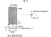
- FIG. 13 is a diagram showing the relationship between the permanent magnet 100, the camera shake correction coil 101 and the center of gravity G 'of the camera shake correction movable part (not shown) provided in the conventional camera module. As shown in FIG. 13, when a current is applied to the camera shake correction coil 101, an electromagnetic force acts on the camera shake correction coil 101 in a direction perpendicular to the optical axis in accordance with Fleming's left method rule.
- the camera shake correction coil 101 is fixed to a base (not shown), a reaction force in a direction perpendicular to the optical axis acts on the permanent magnet 100 in a direction opposite to the electromagnetic force. .
- the rotational torque T ′ acts around the center of gravity G ′ due to the reaction force on the movable portion for correcting camera shake.
- FIG. 14 shows an example of frequency characteristics of the movable part for shake correction when such rotational torque T ′ is applied.
- FIG. 14 is a Bode diagram regarding the motion of the movable part for camera shake correction, and shows only the gain characteristics.
- the gain curve 102 has a primary resonance 103.
- the primary resonance 103 is determined by the mass of the movable part for shake correction and the spring constant of four suspension wires (not shown), and is generated even when the rotational torque T ′ is not applied.
- the resonance 104 is generated at a frequency determined by a spring constant or the like of the side plate spring.
- a lens holder is provided via upper and lower leaf springs (corresponding to an upper leaf spring and a lower leaf spring in the lens driving device of Patent Document 1) by a magnet holder provided in an autofocus drive unit. (All not shown) are supported. Accordingly, when the magnet holder is rotated by the action of the rotational torque T ', the lens holder also tries to rotate via the upper and lower leaf springs, and a moment is generated in the autofocus drive unit. Then, resonance 105 occurs at a frequency determined by the moment of inertia of the autofocus drive unit and the spring constants of the upper and lower leaf springs supporting the autofocus drive unit.
- the frequency of each resonance is not determined only by the spring constant of a specific spring, but is determined by the influence of a plurality of springs.
- the frequency of the resonance 105 is lower than the frequency of the resonance 104, depending on the design of the camera module, the level of these frequencies may be reversed.
- the magnitude of the resonance peak is affected by the amount of deviation between the center of gravity G 'and the position of action such as the force acting on the permanent magnet, the magnitude of the damping effect on the spring, and the like.
- the lens driving device and the conventional camera module disclosed in Patent Document 1 have a structure in which a resonance phenomenon may occur, and there is a possibility that the servo performance of the camera shake correction unit is lowered. Therefore, it is desirable to remove the cause system of the resonance phenomenon or reduce the influence of the resonance phenomenon.
- the lens driving device and the conventional camera module disclosed in Patent Document 1 relate to a camera module having an autofocus function.
- the same problem occurs even when camera shake correction is performed in a fixed focus type camera module.
- the present invention has been made in view of the above-described problems, and an object of the present invention is to accurately perform camera shake correction by improving servo performance by reducing resonance peaks in a camera module having a camera shake correction function. It is to provide a camera module.
- a camera module includes an imaging lens and a driving unit that moves the imaging lens in a direction perpendicular to the optical axis, and the driving unit includes A movable portion on which an imaging lens is mounted; and a fixed portion that is not displaced during camera shake correction.
- One of the movable portion or the fixed portion is provided with a permanent magnet, and the other is provided with a coil.
- One of the magnetic poles of the permanent magnet faces the optical axis, and a surface of the coil perpendicular to the winding axis of the coil is perpendicular to the polarization plane of the permanent magnet and substantially perpendicular to the optical axis.
- the coil is arranged in parallel to the surface, and the coil is arranged to be biased toward the center of gravity of the movable part with respect to the polarization surface.
- the camera module can perform camera shake correction with high accuracy by improving the servo performance of the driving unit.
- FIG. 2 is a cross-sectional view of the camera module shown in FIG.
- FIG. 3 is a cross-sectional view of the camera module shown in FIG.
- It is principal part sectional drawing which shows an example of the positional relationship of a pair of permanent magnet and the coil for OIS with which the camera module shown in FIG. 2 is provided.
- It is a Bode diagram regarding the motion of the OIS movable part with which the camera module concerning Embodiment 1 of the present invention is provided, and is a figure showing only a gain characteristic.
- Embodiment 1 Hereinafter, an embodiment of the present invention will be described in detail with reference to FIGS. 1 to 5.
- a camera module having an optical image stabilization (OIS: Optical Image Stabilizer) function and an autofocus (AF) function will be described as an example. The same applies to the second to fifth embodiments.
- OIS optical image stabilization
- AF autofocus
- FIG. 1 is a perspective view schematically showing a schematic configuration of a camera module 50 of the present embodiment.
- the camera module 50 includes a lens driving device 1 including an imaging lens 4, an imaging unit 2, and a cover 3 that covers the lens driving device 1.
- the lens driving device 1 and the imaging unit 2 are stacked in this order from the imaging unit 2 in the direction of the optical axis 4a (hereinafter abbreviated as the optical axis 4a) of the imaging lens 4.
- the lens driving device 1 side (subject side) will be described as the upper side, and the imaging unit 2 side will be described as the lower side.
- the definition does not prescribe the vertical direction when the camera module 50 is used, and for example, the vertical direction may be reversed.
- the left side toward the paper surface is the left side
- the right side is the right side.
- the cover 3 has a box shape that covers the imaging unit 2, the lens driving device 1, and the imaging lens 4 from above the imaging lens 4.
- An opening 3 a is provided at a position corresponding to the upper side of the imaging lens 4 in the cover 3.
- the inside of the cover 3 may be black that does not reflect light.
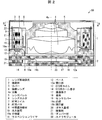
- FIGS. 2 is a cross-sectional view taken along line AA of the camera module 50 shown in FIG. 1, and is a cross-sectional view of the center portion of the camera module 50 cut along the direction of the optical axis 4a.
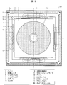
- 3 is a cross-sectional view taken along line BB of the camera module 50 shown in FIG. 2, and a space formed between the inside of the cover 3 and the upper surface of a lens barrel 5 described later is a direction perpendicular to the optical axis 4a. It is sectional drawing cut
- the lens driving device 1 is a device for driving the imaging lens 4 in two directions, ie, the direction of the optical axis 4a and the direction perpendicular to the optical axis 4a.
- the lens driving device 1 includes a plurality (three in FIG. 2) of imaging lenses 4, a lens barrel 5, a lens holder 6, and an AF coil 7 wound around the lens holder 6.
- the plurality of imaging lenses 4, the lens barrel 5, the lens holder 6, and the AF coil 7 function as an AF movable unit that is movable (that is, whose position is changed) in the direction of the optical axis 4 a during autofocus.
- the imaging lens 4 guides light from the outside to an imaging device 17 (described later) provided in the imaging unit 2.
- the axis of the image sensor 17 coincides with the optical axis 4 a of the imaging lens 4.
- the lens barrel 5 holds a plurality (three in FIG. 2) of imaging lenses 4 therein.
- the axis of the lens barrel 5 also coincides with the optical axis 4a.
- the lens barrel 5 has a cylindrical outer shape, but is not limited to this.
- a lens barrel having a rectangular parallelepiped shape may be used.
- the lens holder 6 is supported by the intermediate holding member 9 so as to be movable in the direction of the optical axis 4a by AF springs 8 disposed in pairs at a predetermined interval between the upper and lower portions of the lens holder 6.
- the lens barrel 5 and the lens holder 6 may be fixed with an adhesive (not shown), or may be fixed with a screw or the like. These may be used in combination.
- the AF coil 7 is arranged and fixed on the outer side surface of the lens holder 6.
- the AF coil 7 is wound in a substantially square shape so as to surround the lens barrel 5.
- the axis of the AF coil 7 coincides with the optical axis 4a.
- the permanent magnet 10 is disposed so as to face each outer side surface of the AF coil 7 wound in a substantially rectangular shape.
- the permanent magnet 10 is commonly used for AF and OIS, and functions as a dual-purpose magnet.
- the permanent magnets 10 are arranged with respect to the opposing permanent magnets 10 such that the magnetic poles having the same polarity face each other toward the optical axis 4a (that is, the magnetic poles having the same polarity face the AF coil 7). Yes.
- the lower surface of the permanent magnet 10 is a surface orthogonal to the polarization surface 10a of the permanent magnet 10 and perpendicular to the optical axis 4a, and faces the upper surface of an OIS coil (coil) 13 described later.
- the “polarization surface” refers to a boundary surface between the N-pole region and the S-pole region in the permanent magnet 10.
- the S pole may face the optical axis 4a side, for example. In other words, it is only necessary that one magnetic pole of the permanent magnet 10 is opposed to the optical axis 4a.
- the AF coil 7 and the permanent magnet 10 function as an AF driving unit that drives the imaging lens 4 in the direction of the optical axis 4a for autofocusing.
- the AF spring 8 is a metal spring widely used in existing camera modules with an AF function.
- the AF spring 8 is disposed so as to surround the lens barrel 5.
- the inner end of the AF spring 8 disposed above is fixed to the upper portion of the lens holder 6, and the outer end of the AF spring 8 disposed above is held in the middle. It is fixed to the member 9.
- the inner end of the AF spring 8 disposed below is fixed to the lower portion of the lens holder 6, and the outer end of the AF spring 8 disposed below is fixed to the intermediate holding member 9.
- the permanent magnet 10 is fixed to the intermediate holding member 9.
- the AF spring 8 supports the lens holder 6 so as to be movable up and down.
- the AF spring 8 may support the lens holder 6 and the intermediate holding member 9 so as to be movable in both directions when no current flows through the AF coil 7.
- a downward force may be applied by contact.
- the AF spring 8 has an extending portion 8a protruding to the outside of an intermediate holding member 9 described later, and the upper end of the suspension wire 11 is fixed to the extending portion 8a.
- the upper end of the suspension wire 11 is connected to the extending portion 8a of the AF spring 8 in order to make electrical connection using the AF spring 8 and the suspension wire 11 as energizing means for the AF coil 7 and the like.
- the extending portion 8a acts as a shock absorber function of the suspension wire 11.
- the extension portion 8a bends and suppresses the deformation amount of the suspension wire 11, so that it is possible to prevent the occurrence of tensile fracture or buckling.
- the lower end of the suspension wire 11 is fixed to the base 12.
- the lower end of the suspension wire 11 may be fixed to a substrate (not shown) connected to the base 12. By connecting to this board
- the intermediate holding member 9 is supported on the base 12 by four suspension wires 11 so as to be movable in a direction perpendicular to the optical axis 4a.
- a permanent magnet 10 is fixed to the lower part of the intermediate holding member 9.
- the base 12 is a rectangular member having an opening 12a into which a part of the lens barrel 5 can be inserted in the direction of the optical axis 4a.
- An OIS coil 13 is fixed on the upper surface, and an OIS Hall element to be described later is provided inside. 14 is fixed.
- the base 12 functions as an AF fixing portion and an OIS fixing portion (fixing portion) that does not change its position during autofocus and camera shake correction.
- the OIS coil 13 is fixed to the base 12 so as to face the lower surface of the permanent magnet 10, and is arranged on the four sides of the lens driving device 1. Specifically, the upper surface of the OIS coil 13 orthogonal to the winding shaft 13 a of the OIS coil 13 is disposed so as to face the lower surface of the permanent magnet 10 in parallel.
- the OIS coil 13 is used to drive the OIS movable portion in one direction, as a pair of ones arranged on two opposing sides of the base 12. Further, another pair of OIS coils 13 are arranged on the remaining two opposite sides, and are used for driving in another direction.
- one of the pair of OIS coils 13 is divided into two.
- the direction of the bisected virtual dividing line (not shown) coincides with the direction substantially perpendicular to the polarization surface 10 a of the permanent magnet 10.
- the influence of magnetic field noise generated in the OIS coil 13 is reduced. Can be reduced.
- FIG. 2 is cut at the position where the cross section of the OIS coil 13 divided into two parts appears. The figure is as follows.
- an electromagnetic force is generated between the OIS coil 13 and the permanent magnet 10 by applying a current to the OIS coil 13. Then, by the action of the electromagnetic force, the intermediate holding member 9 and the lens holder 6 and the lens barrel 5 connected to the intermediate holding member 9 via the AF spring 8 are OIS-driven. That is, in addition to the AF movable portion, the intermediate holding member 9 and the permanent magnet 10 are driven in a direction perpendicular to the optical axis 4a as an OIS movable portion (movable portion).
- the OIS movable portion and the OIS fixed portion constitute an OIS drive portion (drive portion).
- the permanent magnet 10 is provided in the OIS movable portion and the OIS coil 13 is provided in the base 12, but the arrangement of the permanent magnet 10 and the OIS coil 13 may be reversed.
- the permanent magnet 10 may be provided on one of the OIS movable portion or the base 12 and the OIS coil 13 may be provided on the other.
- an OIS hall element (displacement detector) 14 for detecting the position (OIS displacement amount) of the OIS movable part with respect to the image sensor 17 is arranged in the vicinity of the intermediate position of the OIS coil 13 divided in two. , Fixed inside the base 12.
- the OIS hall element 14 detects the amount of displacement in the direction perpendicular to the optical axis 4 a of the imaging lens 4.
- the displacement amount corresponds to the OIS displacement amount.
- the hall element for OIS 14 is arranged on two sides to detect displacement in two directions.
- the other Hall element for OIS 14 (not shown) has only to be arranged inside one of the two sides orthogonal to the two sides of the base 12 whose cross section is shown in FIG.
- the OIS coil 13 and the OIS hall element 14 are fixed to the base 12 in a state of being opposed to each other, energization is facilitated as compared with the case where they are arranged on the OIS movable portion side. . Further, since the OIS hall element 14 can appropriately control the OIS displacement amount and the moving direction of the OIS movable portion in accordance with the amount and direction of camera shake, the correction accuracy of camera shake correction can be improved.
- the camera module 50 also includes an AF hall element 15 for detecting the amount of displacement of the AF movable part. As shown in FIG. 3, the hall element 15 for AF is fixed to the intermediate holding member 9 disposed at one corner portion of the lens driving device 1. An auxiliary permanent magnet 16 is provided at one corner of the lens holder 6 so as to face the AF hall element 15.
- the auxiliary permanent magnet 16 is relatively displaced with respect to the AF hall element 15, whereby the displacement amount of the AF movable part can be detected.
- the AF hall element 15 is fixed to the intermediate holding member 9 and the auxiliary permanent magnet 16 is fixed to the lens holder 6, but the arrangement may be reversed.
- the camera module 50 may include six or more suspension wires 11 for energization of the AF hall element 15. For example, when there are six suspension wires 11, four are used for energizing the AF hall element 15 and two are used for energizing the AF coil 7.
- the imaging unit 2 images light that has passed through the imaging lens 4.
- the imaging unit 2 includes an imaging element 17, a substrate 18, a sensor cover 19, and a glass substrate 20.
- the image sensor 17 is mounted on the substrate 18 and receives light that has arrived via the image pickup lens 4 and performs photoelectric conversion to obtain a subject image formed on the image sensor 17.
- the substrate 18 and the sensor cover 19 are bonded and fixed in a state where the gap formed between the upper surface of the substrate 18 and the lower surface of the sensor cover 19 is closed by the adhesive 21.
- the sensor cover 19 is a rectangular member disposed below the base 12.
- the sensor cover 19 is placed on the image sensor 17 so as to cover the entire image sensor 17.
- a convex portion 19 a that abuts on 17 is provided.
- the sensor cover 19 has an opening 19b penetrating in the vertical direction at the center thereof.
- the positional accuracy of the imaging lens 4 in the direction of the optical axis 4a with respect to the imaging device 17 is improved by the tip surface of the convex portion 19a contacting the imaging device 17.
- the opening 19b is blocked by the glass substrate 20.
- the material of the glass substrate 20 is not limited, For example, what provided the infrared cut function may be used.
- a damper material 22 such as an ultraviolet curable gel is applied to a joint portion between the suspension wire 11 and the extension portion 8 a of the AF spring 8.
- the damper material 22 will be described later.
- FIG. 4 is a cross-sectional view of the main part showing an example of the positional relationship between the pair of permanent magnets 10 and the OIS coil 13 provided in the camera module 50 according to the present embodiment.
- the winding shaft 13a of the OIS coil 13 is biased toward the center of gravity G of the OIS movable portion with respect to the polarization surface 10a of the permanent magnet 10, in other words, the OIS coil 13 causes the polarization surface 10a to be in contact with the polarization surface 10a.
- the OIS movable part is arranged so as to be biased toward the center of gravity G, a large amount of magnetic flux components inclined with respect to the polarization surface 10a are incident particularly on the coil winding portion on the center of gravity G side.
- the electromagnetic force 24 generated when a current is applied to the OIS coil 13 also acts in a direction inclined with respect to a direction perpendicular to the optical axis 4a (hereinafter referred to as a horizontal direction).
- a horizontal direction a direction inclined with respect to a direction perpendicular to the optical axis 4a
- the force components in the direction of the axis 4a cancel each other, if they are arranged in a biased manner, they cannot be canceled out and the force component in the direction of the optical axis 4a remains.
- the OIS coil 13 positioned on the left side with respect to the optical axis 4a has a left side and a lower side relative to the horizontal direction.
- An inclined electromagnetic force 24 acts.
- an electromagnetic force 24 inclined to the left and upward with respect to the horizontal direction acts on the OIS coil 13 positioned on the right side with respect to the optical axis 4a.
- the reaction force 25 acts on the permanent magnet 10 by the reaction of the electromagnetic force 24. Specifically, a reaction force 25 inclined rightward and upward with respect to the horizontal direction acts on the lower end portion of the permanent magnet 10 positioned on the left side with respect to the optical axis 4a. On the other hand, a reaction force 25 inclined rightward and downward with respect to the horizontal direction acts on the lower end portion of the permanent magnet 10 positioned on the right side with respect to the optical axis 4a.
- the reaction force 25 acts on the permanent magnet 10 as a component force 25b in the horizontal direction and a component force 25a in the direction of the optical axis 4a (hereinafter referred to as the vertical direction).
- each of the horizontal component forces 25b acting on the pair of permanent magnets 10 produces a counterclockwise rotational torque T1b with respect to the center of gravity G of the OIS movable portion.
- each of the vertical component forces 25a acting on the pair of permanent magnets 10 generates a clockwise rotational torque T1a with respect to the center of gravity G.
- FIG. 5 is a Bode diagram relating to the motion of the OIS movable part provided in the camera module 50, and is a diagram showing only gain characteristics.
- the camera module 50 is subjected to a resonance peak reduction process using a damping effect by the damper material 22.
- a damper material 22 such as an ultraviolet curable gel is applied to a joint portion between the suspension wire 11 and the extension portion 8 a of the AF spring 8.
- the intermediate holding member 9 since the intermediate holding member 9 also performs a rotational motion by the action of the rotational torque T1 (see FIG. 4), a resonance phenomenon in the rotational mode occurs due to the rotational motion. However, since the vibration of the extending portion 8a caused by the resonance phenomenon is suppressed by the damper material 22, the resonance peak of the resonance phenomenon caused by the vibration can be reduced.
- the location where the damper material 22 is applied is not limited to the above case.
- the permanent magnet 10 and the intermediate holding member 9 may be filled by filling the gap between the permanent magnet 10 and the OIS coil 13 with the damper material 22. Can be suppressed.
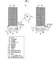
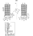
- FIG. 6 is a cross-sectional view of the main part showing an example of the positional relationship between the pair of permanent magnets 10 and the OIS coil 13 provided in the camera module 50 according to the present embodiment.
- the camera module 50 according to the present embodiment is different from the camera module 50 according to the first embodiment in that the winding shaft 13a of the OIS coil 13 is OIS with respect to the polarization surface 10a of the permanent magnet 10 as shown in FIG. Only the left permanent magnet 10 and the OIS coil 13 are biased toward the center of gravity G of the movable part. Thus, the position of the OIS coil 13 with respect to the permanent magnet 10 may be biased toward the center of gravity G only on one side.
- the positional relationship between the left permanent magnet 10 and the OIS coil 13 in FIG. 6 is the same as the positional relationship between the left permanent magnet 10 and the OIS coil 13 in FIG.
- the reaction force 25 generated at the lower end of the permanent magnet 10 is a vertical component force 25a and a horizontal component force 25b.
- the vertical component force 25a applies a clockwise rotational torque T2a to the center of gravity G of the OIS movable portion
- the horizontal component force 25b applies a counterclockwise rotational torque to the center of gravity G. Torques cancel each other out.
- the positional relationship between the right permanent magnet 10 and the OIS coil 13 in FIG. 6 is such that the polarization surface 10a of the permanent magnet 10 and the winding shaft 13a of the OIS coil 13 are on the same plane. . Accordingly, since the reaction force 25 acting on the right permanent magnet 10 does not have a vertical component force, the reaction force 25 itself gives a counterclockwise rotational torque to the center of gravity G of the OIS movable portion.
- the sum of the counterclockwise rotational torque generated based on the left horizontal component force 25b and the counterclockwise rotational torque generated based on the right horizontal component force 25b is the counterclockwise direction.
- the rotational torque is T2b.
- the rotational torque T2 (counterclockwise) obtained by offsetting the rotational torque T2b to a certain extent by the rotational torque T2a finally acts on the center of gravity G of the OIS movable portion. Therefore, the resonance peak of the resonance phenomenon caused by the rotational torque acting on the gravity center G can be reduced.
- the component force 25a in the vertical direction acting on the permanent magnet 10 is also a force that translates the OIS movable portion in the direction of the optical axis 4a. Accordingly, the extension 8a of the upper AF spring 8 may resonate due to the vertical component force 25a, and a new resonance peak may be generated.
- the control of the OIS movable portion is performed based on the detection signal of the OIS hall element 14, if the OIS hall element 14 does not detect the displacement in the direction of the optical axis 4a based on the vibration, the OIS drive The influence on the servo performance of the part can be reduced.
- the Hall element 14 for OIS basically detects the displacement of the permanent magnet 10 in the direction of the optical axis 4a. Since the displacement of the permanent magnet 10 in the direction of the optical axis 4a does not contribute to camera shake correction, the OIS Hall element 14 performs erroneous detection of the displacement in the direction of the optical axis 4a as a displacement in the direction perpendicular to the optical axis 4a. Will end up.
- the amount of displacement in the direction of the optical axis 4a is small in the right portion of the OIS movable portion. Therefore, by disposing the OIS hall element 14 at a position facing the lower surface of the right permanent magnet 10, the amount of displacement in the direction of the optical axis 4a detected by the OIS hall element 14 can be reduced. The displacement detection signal level can be lowered.
- the OIS Hall element 14 be disposed on the side where the position of the OIS coil 13 is not biased toward the center of gravity G of the OIS movable portion with respect to the permanent magnet 10. .
- FIG. 7 is a cross-sectional view of the main part showing a state in which the pair of permanent magnets 10 is displaced in the direction indicated by the arrow in the drawing based on the positional relationship shown in FIG.
- the pair of permanent magnets 10 In the positional relationship between the pair of permanent magnets 10 and the OIS coil 13 shown in FIG. 6, when a current is applied to the pair of OIS coils 13 in the direction shown in the figure, the pair of permanent magnets 10 is viewed in the direction of the arrow by OIS driving. Displace in the direction (right side). In the state after this displacement, the positional relationship between the left permanent magnet 10 and the OIS coil 13 is such that the polarization surface 10a of the permanent magnet 10 and the winding shaft 13a of the OIS coil 13 are on the same plane as shown in FIG. It will be on top. On the other hand, the positional relationship between the right permanent magnet 10 and the OIS coil 13 is such that the position of the OIS coil 13 is biased toward the center of gravity G of the OIS movable portion with respect to the permanent magnet 10.
- the vertical component force 25a of the reaction force 25 acting on the lower end of the right permanent magnet 10 generates a clockwise rotational torque T2a '. Further, based on each of the horizontal component forces 25b acting on both permanent magnets 10, a counterclockwise rotational torque T2b 'is generated. Then, since the rotational torque T2a 'acts in the direction to cancel the rotational torque T2b', the counterclockwise rotational torque T2 'finally acts on the center of gravity G of the OIS movable portion.
- the OIS Hall element 14 If the OIS Hall element 14 is arranged so as to face the lower surface of the right permanent magnet 10, the OIS Hall element 14 detects even a displacement in the direction of the optical axis 4a in the state after the OIS drive. There is a fear. However, this is unavoidable, and in the state where the OIS movable part is in the neutral position before the OIS drive, the OIS Hall element 14 is positioned at the position of the OIS coil 13 with respect to the permanent magnet 10. It is desirable that it be arranged on the side that is not biased toward the center of gravity G.
- the displacement amount in the direction of the optical axis 4a is the positional relationship between the permanent magnet 10 and the OIS coil 13 shown in FIG. More than in the case of.
- the OIS Hall element 14 is arranged so as to face the lower surface of the left permanent magnet 10, the OIS Hall element 14 detects more displacement in the direction of the optical axis 4a that should not be detected. Because it will do.
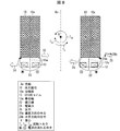
- FIG. 8 is a cross-sectional view of the main part showing an example of the positional relationship between the pair of permanent magnets 10 and the OIS coil 13 provided in the camera module 50 according to the present embodiment.
- FIG. 9 is a cross-sectional view of the main part showing a state in which the pair of permanent magnets 10 is displaced in the direction indicated by the arrow in the drawing based on the positional relationship shown in FIG.
- the camera module 50 according to the present embodiment differs from the camera module 50 according to the first and second embodiments in that the winding shaft 13a of the OIS coil 13 is against the polarization surface 10a of the permanent magnet 10 as shown in FIG. Only the right permanent magnet 10 and the OIS coil 13 are biased toward the center of gravity G of the OIS movable portion. Further, the second embodiment is different from the second embodiment in that the position of the OIS coil 13 with respect to the permanent magnet 10 is biased toward the center of gravity G not on the left side but on the right side.
- the camera module 50 according to the present embodiment and the camera module 50 according to the second embodiment are merely reversed in the left-right relationship, and the principle of improving the servo performance of the OIS drive unit is the camera module according to the second embodiment. 50, the detailed description is omitted.
- the OIS hall element 14 it is desirable to arrange the OIS hall element 14 so as to face the lower surface of the left permanent magnet 10.
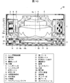
- FIG. 10 is a cross-sectional view schematically showing a schematic configuration of the camera module 50 according to the present embodiment.
- FIG. 10 corresponds to a cross-sectional view taken along line AA of the camera module 50 shown in FIG.
- the camera module 50 according to the present embodiment differs from the camera module 50 according to the first to third embodiments in that each of the pair of OIS coils 13 faces the upper surface of the permanent magnet 10 as shown in FIG. It is a point arranged in.
- the OIS hall element 14 is disposed so as to face the lower surface of the permanent magnet 10, as in the camera module 50 according to the first to third embodiments.
- a second base 28 is provided in addition to the first base 12 ′ (the same shape and function as the base 12). .
- the second base 28 protrudes from the inside of the cover 3 so as to be disposed in a region between the upper AF spring 8 and the intermediate holding member 9.
- the OIS coil 13 is fixed to the lower surface of the second base 28.
- the OIS hall element 14 can be brought closer to the permanent magnet 10, so that the displacement detection sensitivity of the OIS hall element 14 is increased. Can be increased. Further, the OIS Hall element 14 is less susceptible to magnetic field noise generated by applying a current to the OIS coil 13.
- FIG. 11 is a cross-sectional view of the main part showing an example of the positional relationship between the pair of permanent magnets 10 and the OIS coil 13 provided in the camera module 50 according to the present embodiment.
- the winding shaft 13 a of the OIS coil 13 is OIS movable with respect to the polarization surface 10 a of the permanent magnet 10. It is desirable to arrange the OIS coil 13 so as to be biased toward the center of gravity G of the portion.
- the resonance peak of the resonance phenomenon of the rotation mode generated in the OIS movable part can be reduced.
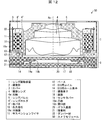
- FIG. 12 is a cross-sectional view schematically showing a schematic configuration of the camera module 50 according to the present embodiment.
- FIG. 12 corresponds to a cross-sectional view taken along line AA of the camera module 50 shown in FIG.
- the camera module 50 does not include the AF coil 7, the AF spring 8, and the intermediate holding member 9, and the imaging lens 4 is a fixed focus lens. Different from the camera module 50 according to 1 to 4.
- the lens holder 6 ′ also has a function as the intermediate holding member 9. Accordingly, the permanent magnet 10 is fixed to the lens holder 6 ′ so that the lower surface thereof faces the OIS coil 13.
- the extension portion 8a of the AF spring 8 provided in the camera module 50 according to the first to fourth embodiments also functions as a shock absorber for protecting the suspension wire 11. Since the camera module 50 according to the present embodiment also includes the suspension wire 11, a leaf spring 8 ′ having an extending portion 8 a is fixed to the upper surface of the lens holder 6 ′ instead of the AF spring 8. And the upper end of the suspension wire 11 is fixed to the extension part 8a.
- the AF driving unit is unnecessary, the configuration in the direction perpendicular to the optical axis 4a of the imaging lens 4 can be simplified. Therefore, it is possible to achieve both the improvement of the accuracy of camera shake correction and the miniaturization of the camera module 50.
- a camera module (50) includes an imaging lens (4) and a driving unit that moves the imaging lens in a direction perpendicular to the optical axis (4a). And a fixed portion (base 12, first base 12 ′, second base 28) that is not displaced during camera shake correction, and a permanent magnet (one of the movable portion and the fixed portion). 10) and a coil (OIS coil 13) is provided on the other side, and one magnetic pole of the permanent magnet faces the optical axis, and the winding axis (13a) of the coil in the coil. Is perpendicular to the polarization plane (10a) of the permanent magnet and is substantially parallel to the plane substantially perpendicular to the optical axis. The coil is based on the polarization plane. ,the above The movable part is arranged to be biased toward the center of gravity (G).
- G center of gravity
- the camera module includes the driving unit that moves the imaging lens in a direction perpendicular to the optical axis
- the driving unit includes a movable unit that mounts the imaging lens and a fixed unit that is not displaced during camera shake correction.
- One of the movable part and the fixed part is provided with a permanent magnet, and the other is provided with a coil.
- one magnetic pole of the permanent magnet is opposed to the optical axis, and the surface of the coil perpendicular to the winding axis of the coil is perpendicular to the polarization surface of the permanent magnet and substantially perpendicular to the optical axis. It faces the parallel plane.
- the coil in the camera module, is arranged so as to be biased toward the center of gravity of the movable portion with respect to the polarization plane. Therefore, more magnetic flux components that are inclined with respect to the polarization plane are incident on the portion on the center of gravity side than the winding axis of the coil, compared to the other portions. Therefore, an electromagnetic force acting on the coil in a direction inclined with respect to the optical axis direction is generated, and a force acting on the permanent magnet when the coil is fixed is also inclined with respect to the direction perpendicular to the optical axis. Occurs in the direction.
- the rotational force acting around the center of gravity of the movable part by the component force in the direction perpendicular to the optical axis of the force acting on the permanent magnet and the force around the center of gravity by the component force in the direction of the optical axis of the force acting on the permanent magnet is that the rotational directions are opposite to each other. Therefore, since the rotational torque is canceled at least to a certain extent, the resonance peak of the resonance phenomenon generated due to the rotational torque can be reduced.
- the camera module (50) according to aspect 2 of the present invention is the camera module (50) according to aspect 1, in which the permanent magnet (10) and the coil (OIS coil 13) correspond to each other in one moving direction of the driving unit.
- each of the pair of coils may be configured to be biased toward the center of gravity (G) of the movable part with respect to the polarization plane (10a).
- the permanent magnet and the coil are provided in pairs corresponding to one moving direction of the driving unit. Therefore, compared with the case where the permanent magnet and the coil are provided one by one corresponding to the moving direction, the driving force of the driving unit (the force acting on the permanent magnet if the coil is fixed) ) Is doubled, the servo performance of the drive unit is further improved.
- each of the pair of coils is arranged to be biased toward the center of gravity of the movable portion with reference to the polarization surface of the opposing permanent magnet.
- each of the pair of coils is fixed to the fixed portion, only one of the pair of coils is compared with the case where the coil is disposed to be biased toward the center of gravity with respect to the polarization plane.
- the rotational torque acting around the center of gravity is doubled by the component force in the optical axis direction of the force acting on the permanent magnet. Therefore, since the canceling effect by the rotational torques in the opposite directions is improved, the generation of the rotational torque that causes the resonance phenomenon can be further reduced.
- a camera module (50) according to an aspect 3 of the present invention is the camera module (50) according to the aspect 1, wherein a displacement detector (OIS Hall element) that detects a displacement amount of the imaging lens (4) in a direction perpendicular to the optical axis (4a). 14), and the permanent magnet (10) and the coil (OIS coil 13) are provided in pairs corresponding to one moving direction of the drive unit, and one of the pair of coils is
- the polarization plane (10a) is used as a reference and is arranged to be biased toward the center of gravity (G) of the movable part, and the displacement detection unit is arranged with one of the pair of coils on the basis of the center of gravity of the movable part.
- positioned on the opposite side may be sufficient.
- a pair of permanent magnets and coils are provided corresponding to one moving direction of the drive unit, and one of the pair of coils is movable with reference to the polarization plane of the opposing permanent magnet. It is biased toward the center of gravity of the part.
- each of the pair of coils is based on the polarization surface.
- the component force in the optical axis direction of the force acting on the permanent magnet is 1 ⁇ 2 times. Therefore, for example, based on the component force in the optical axis direction, the resonance peak of the resonance phenomenon occurring near the connection point between the suspension wire and the AF spring can be reduced, and the servo performance of the camera module is improved. To do.
- the displacement detection unit that detects the amount of displacement in the direction perpendicular to the optical axis of the imaging lens is disposed on the opposite side of the pair of coils with the center of gravity of the movable unit as a reference. It is provided so as to face the permanent magnet.
- the component force in the optical axis direction does not act on the permanent magnet disposed on the side opposite to one of the pair of coils.
- the amount of displacement in the optical axis direction is smaller than that of the other permanent magnet to which the component force acts directly.
- the optical axis direction of the permanent magnet is compared with the case where the displacement detection unit is provided so as to face the permanent magnet disposed on one side of the pair of coils with the center of gravity of the movable unit as a reference. It is possible to reduce an erroneous displacement detection signal level caused by detecting the displacement of the first. Therefore, the camera module can detect the displacement in the direction perpendicular to the optical axis of the imaging lens with high accuracy.
- the permanent magnet (10) may be provided in the movable part.
- the movable part is equipped with an imaging lens, when the coil is provided in the movable part, the coil can be arranged closer to the center of gravity of the movable part than when the coil is provided in the fixed part. Can not.
- the permanent magnet is provided in the movable part. Therefore, the coil is provided in the fixed portion, and can be arranged closer to the center of gravity. Therefore, the component force in the direction perpendicular to the optical axis of the force acting on the permanent magnet can be increased, and the canceling effect by the rotational torques in opposite directions is improved. As a result, generation
- the displacement detection unit by fixing the displacement detection unit to the fixed unit, it is possible to more easily energize the coil and the displacement detection unit as compared with the case where the coil and the displacement detection unit are provided in the movable unit. Furthermore, when the camera module has an AF function, the permanent magnet can be shared as an AF magnet and an OIS magnet, and the number of parts can be reduced.
- the camera module (50) according to aspect 5 of the present invention may be configured to further include a damper material (22) for suppressing vibration of the movable part in any of the above aspects 1 to 4.
- the camera module includes the damper material. Therefore, by providing the damper material near, for example, a connection portion between the suspension wire and the AF spring, it is possible to suppress the vibration of the movable part caused by the resonance phenomenon. Therefore, the resonance peak of the resonance phenomenon that occurs in the movable part can be further reduced, and the servo performance of the drive part is further improved.
- a camera module (50) according to aspect 6 of the present invention is the camera module (50) according to aspect 3, in which the surface of the permanent magnet (10) facing the coil (OIS coil 13) and the displacement detector (OIS Hall element 14) are arranged. ) And the surface of the permanent magnet facing each other may be different.
- the surface of the permanent magnet that faces the coil is different from the surface of the permanent magnet that faces the displacement detector. Accordingly, since the coil is not interposed between the displacement detection unit and the surface of the permanent magnet facing the displacement detection unit, the displacement detection unit is brought closer to the permanent magnet as compared with the case where the coil is interposed. be able to. Therefore, the displacement detection sensitivity of the displacement detector can be increased, and the influence of magnetic field noise generated by applying a current to the coil on the displacement detector can be reduced.
Landscapes
- Physics & Mathematics (AREA)
- General Physics & Mathematics (AREA)
- Optics & Photonics (AREA)
- Engineering & Computer Science (AREA)
- Power Engineering (AREA)
- Chemical & Material Sciences (AREA)
- Combustion & Propulsion (AREA)
- Electromagnetism (AREA)
- Adjustment Of Camera Lenses (AREA)
- Lens Barrels (AREA)
- Studio Devices (AREA)
Abstract
Description
以下、本発明の実施の一形態について、図1から図5を参照しながら、詳細に説明する。
まず、図1に基づき、カメラモジュール50の全体構造について説明する。図1は、本実施形態のカメラモジュール50の概略構成を模式的に示す斜視図である。
レンズ駆動装置1は、撮像レンズ4を光軸4a方向および光軸4aに垂直な方向の2方向に駆動するための装置である。図2に示すように、レンズ駆動装置1は、複数(図2では3枚)の撮像レンズ4、レンズバレル5、レンズホルダ6および当該レンズホルダ6に巻回されるAF用コイル7を備える。複数の撮像レンズ4、レンズバレル5、レンズホルダ6およびAF用コイル7は、オートフォーカス時に光軸4a方向に可動(つまり、位置が変移)するAF可動部として機能する。
撮像部2は、撮像レンズ4を経由した光を撮像する。図2に示すように、撮像部2は、撮像素子17、基板18、センサカバー19およびガラス基板20を備えている。
次に、図4を参照して、永久磁石10とOIS用コイル13との位置関係について説明する。図4は、本実施形態に係るカメラモジュール50が備えている、一対の永久磁石10とOIS用コイル13との位置関係の一例を示す要部断面図である。
次に、図5を参照して、OIS可動部の重心Gに回転トルクT1が作用する場合における、当該OIS可動部の周波数特性の例について説明する。図5は、カメラモジュール50が備えているOIS可動部の運動に関するボード線図であり、ゲイン特性のみを示す図である。
図2に示すように、カメラモジュール50には、ダンパー材22によるダンピング効果を利用した共振ピーク低減処置が施されている。具体的には、サスペンションワイヤ11とAF用バネ8の延出部8aとの結合部に、例えば紫外線硬化ゲルのようなダンパー材22が塗布されている。
本発明の他の実施形態について、図6および図7に基づいて説明すれば、以下の通りである。なお、説明の便宜上、前記実施形態1にて説明した部材と同じ機能を有する部材については、同じ符号を付記し、その説明を省略する。
まず、図6を参照して、本発明の実施形態2に係るカメラモジュール50が備えている永久磁石10とOIS用コイル13との位置関係について説明する。図6は、本実施形態に係るカメラモジュール50が備えている、一対の永久磁石10とOIS用コイル13との位置関係の一例を示す要部断面図である。
次に、図7を参照して、OIS駆動後における永久磁石10とOIS用コイル13との位置関係について説明する。図7は、図6に示された上記位置関係から、一対の永久磁石10が図中の矢視方向に変位した状態を示す要部断面図である。
本発明の他の実施形態について、図8および図9に基づいて説明すれば、以下の通りである。なお、説明の便宜上、前記各実施形態にて説明した部材と同じ機能を有する部材については、同じ符号を付記し、その説明を省略する。
以下、図8を参照して、本発明の実施形態3に係るカメラモジュール50が備えている永久磁石10とOIS用コイル13との位置関係について説明する。図8は、本実施形態に係るカメラモジュール50が備えている、一対の永久磁石10とOIS用コイル13との位置関係の一例を示す要部断面図である。また、図9は、図8に示された上記位置関係から、一対の永久磁石10が図中の矢視方向に変位した状態を示す要部断面図である。
本発明の他の実施形態について、図10および図11に基づいて説明すれば、以下の通りである。なお、説明の便宜上、前記各実施形態にて説明した部材と同じ機能を有する部材については、同じ符号を付記し、その説明を省略する。
まず、図10に基づき、本発明の実施形態4に係るカメラモジュール50の各部の構造について説明する。図10は、本実施形態に係るカメラモジュール50の概略構成を模式的に示す断面図である。なお、図10は、図1に示すカメラモジュール50のA-A線矢視断面図に相当する。
次に、図11を参照して、本実施形態に係るカメラモジュール50が備えている永久磁石10とOIS用コイル13との位置関係について説明する。図11は、本実施形態に係るカメラモジュール50が備えている、一対の永久磁石10とOIS用コイル13との位置関係の一例を示す要部断面図である。
本発明の他の実施形態について、図12に基づいて説明すれば、以下の通りである。なお、説明の便宜上、前記各実施形態にて説明した部材と同じ機能を有する部材については、同じ符号を付記し、その説明を省略する。
以下、図12に基づき、本発明の実施形態5に係るカメラモジュール50の各部の構造について説明する。図12は、本実施形態に係るカメラモジュール50の概略構成を模式的に示す断面図である。なお、図12は、図1に示すカメラモジュール50のA-A線矢視断面図に相当する。
本発明の態様1に係るカメラモジュール(50)は、撮像レンズ(4)と、上記撮像レンズを光軸(4a)に垂直な方向に移動させる駆動部と、を備え、上記駆動部は、上記撮像レンズを搭載する可動部と、手振れ補正時に変位しない固定部(ベース12、第1ベース12’、第2ベース28)と、を備え、上記可動部または上記固定部の一方には永久磁石(10)が備えられるとともに、他方にはコイル(OIS用コイル13)が備えられ、上記永久磁石の一方の磁極は、上記光軸と対向しており、上記コイルにおける上記コイルの巻き軸(13a)と直交する面は、上記永久磁石における上記永久磁石の分極面(10a)と直交するとともに上記光軸にほぼ垂直な面と、平行に対向しており、上記コイルは、上記分極面を基準として、上記可動部の重心(G)の側に偏って配置されている。
4a 光軸
5 レンズバレル(可動部)
6 レンズホルダ(可動部)
7 AF用コイル(可動部)
9 中間保持部材(可動部)
10 永久磁石(可動部)
10a 分極面
12 ベース(固定部)
13 OIS用コイル(コイル)
13a 巻き軸
14 OIS用ホール素子(変位検出部)
22 ダンパー材
50 カメラモジュール
Claims (5)
- 撮像レンズと、
上記撮像レンズを光軸に垂直な方向に移動させる駆動部と、を備え、
上記駆動部は、上記撮像レンズを搭載する可動部と、手振れ補正時に変位しない固定部と、を備え、
上記可動部または上記固定部の一方には永久磁石が備えられるとともに、他方にはコイルが備えられ、
上記永久磁石の一方の磁極は、上記光軸と対向しており、
上記コイルにおける上記コイルの巻き軸と直交する面は、上記永久磁石における上記永久磁石の分極面と直交するとともに上記光軸にほぼ垂直な面と、平行に対向しており、
上記コイルは、上記分極面を基準として、上記可動部の重心の側に偏って配置されていることを特徴とするカメラモジュール。 - 上記永久磁石および上記コイルは、上記駆動部の1つの移動方向に対応して一対ずつ備えられるとともに、上記一対のコイルの各々は、上記分極面を基準として、上記可動部の重心の側に偏って配置されていることを特徴とする請求項1に記載のカメラモジュール。
- 上記撮像レンズの上記光軸に垂直な方向の変位量を検出する変位検出部を、さらに備え、
上記永久磁石および上記コイルは、上記駆動部の1つの移動方向に対応して一対ずつ備えられるとともに、上記一対のコイルの一方は、上記分極面を基準として、上記可動部の重心の側に偏って配置されており、
上記変位検出部は、上記可動部の重心を基準として、上記一対のコイルの一方と反対の側に配置された上記永久磁石と対向するように配置されていることを特徴とする請求項1に記載のカメラモジュール。 - 上記永久磁石は、上記可動部に備えられたことを特徴とする請求項1から3のいずれか1項に記載のカメラモジュール。
- 上記可動部の振動を抑制するダンパー材を、さらに備えたことを特徴とする請求項1から4のいずれか1項に記載のカメラモジュール。
Priority Applications (3)
| Application Number | Priority Date | Filing Date | Title |
|---|---|---|---|
| CN201680041423.5A CN107889528A (zh) | 2015-07-13 | 2016-05-25 | 相机模块 |
| US15/577,828 US20180164661A1 (en) | 2015-07-13 | 2016-05-25 | Camera module |
| JP2017528320A JP6621475B2 (ja) | 2015-07-13 | 2016-05-25 | カメラモジュール |
Applications Claiming Priority (2)
| Application Number | Priority Date | Filing Date | Title |
|---|---|---|---|
| JP2015139939 | 2015-07-13 | ||
| JP2015-139939 | 2015-07-13 |
Publications (1)
| Publication Number | Publication Date |
|---|---|
| WO2017010174A1 true WO2017010174A1 (ja) | 2017-01-19 |
Family
ID=57756904
Family Applications (1)
| Application Number | Title | Priority Date | Filing Date |
|---|---|---|---|
| PCT/JP2016/065464 WO2017010174A1 (ja) | 2015-07-13 | 2016-05-25 | カメラモジュール |
Country Status (4)
| Country | Link |
|---|---|
| US (1) | US20180164661A1 (ja) |
| JP (1) | JP6621475B2 (ja) |
| CN (1) | CN107889528A (ja) |
| WO (1) | WO2017010174A1 (ja) |
Cited By (3)
| Publication number | Priority date | Publication date | Assignee | Title |
|---|---|---|---|---|
| JP2017083557A (ja) * | 2015-10-26 | 2017-05-18 | キヤノン株式会社 | 光学シフト装置および光学機器 |
| CN110361908A (zh) * | 2018-03-26 | 2019-10-22 | 日本电产三协株式会社 | 带抖动修正功能的光学单元 |
| JP2021162739A (ja) * | 2020-04-01 | 2021-10-11 | 日本電産サンキョー株式会社 | 測定システムおよび測定方法 |
Families Citing this family (6)
| Publication number | Priority date | Publication date | Assignee | Title |
|---|---|---|---|---|
| JP6852433B2 (ja) * | 2017-02-09 | 2021-03-31 | Tdk株式会社 | レンズ駆動装置及び電磁駆動ユニット |
| US10866385B2 (en) * | 2017-05-12 | 2020-12-15 | Tdk Taiwan Corp. | Optical system |
| US11119333B2 (en) | 2018-09-26 | 2021-09-14 | Apple Inc. | Damper arrangement for actuator damping |
| US20200409242A1 (en) * | 2019-06-27 | 2020-12-31 | Michael Isakov | Garment with integrated camera with stabilizer system |
| CN212484036U (zh) * | 2019-10-09 | 2021-02-05 | 台湾东电化股份有限公司 | 光学元件驱动机构 |
| CN214503997U (zh) * | 2020-03-06 | 2021-10-26 | 台湾东电化股份有限公司 | 光学元件驱动机构 |
Citations (1)
| Publication number | Priority date | Publication date | Assignee | Title |
|---|---|---|---|---|
| JP2015055776A (ja) * | 2013-09-12 | 2015-03-23 | シャープ株式会社 | カメラモジュール |
Family Cites Families (7)
| Publication number | Priority date | Publication date | Assignee | Title |
|---|---|---|---|---|
| CN102016708B (zh) * | 2008-04-30 | 2013-07-31 | 日本电产三协株式会社 | 带抖动修正功能的光学单元 |
| KR101594296B1 (ko) * | 2009-07-17 | 2016-02-16 | 삼성전자주식회사 | 손떨림 보정장치 |
| JP5348235B2 (ja) * | 2009-08-21 | 2013-11-20 | ミツミ電機株式会社 | レンズホルダ駆動装置、およびそれを搭載したカメラ |
| JP5606819B2 (ja) * | 2010-08-03 | 2014-10-15 | シャープ株式会社 | カメラモジュール |
| JP5821356B2 (ja) * | 2011-07-15 | 2015-11-24 | ミツミ電機株式会社 | レンズ駆動装置 |
| US8698952B2 (en) * | 2011-10-31 | 2014-04-15 | Lg Innotek Co., Ltd. | Camera module |
| US10168545B2 (en) * | 2014-10-16 | 2019-01-01 | Tdk Taiwan Corp. | Optical image stabilizer with improved magnetic disposition |
-
2016
- 2016-05-25 WO PCT/JP2016/065464 patent/WO2017010174A1/ja active Application Filing
- 2016-05-25 CN CN201680041423.5A patent/CN107889528A/zh active Pending
- 2016-05-25 JP JP2017528320A patent/JP6621475B2/ja not_active Expired - Fee Related
- 2016-05-25 US US15/577,828 patent/US20180164661A1/en not_active Abandoned
Patent Citations (1)
| Publication number | Priority date | Publication date | Assignee | Title |
|---|---|---|---|---|
| JP2015055776A (ja) * | 2013-09-12 | 2015-03-23 | シャープ株式会社 | カメラモジュール |
Cited By (3)
| Publication number | Priority date | Publication date | Assignee | Title |
|---|---|---|---|---|
| JP2017083557A (ja) * | 2015-10-26 | 2017-05-18 | キヤノン株式会社 | 光学シフト装置および光学機器 |
| CN110361908A (zh) * | 2018-03-26 | 2019-10-22 | 日本电产三协株式会社 | 带抖动修正功能的光学单元 |
| JP2021162739A (ja) * | 2020-04-01 | 2021-10-11 | 日本電産サンキョー株式会社 | 測定システムおよび測定方法 |
Also Published As
| Publication number | Publication date |
|---|---|
| JP6621475B2 (ja) | 2019-12-18 |
| CN107889528A (zh) | 2018-04-06 |
| JPWO2017010174A1 (ja) | 2018-02-22 |
| US20180164661A1 (en) | 2018-06-14 |
Similar Documents
| Publication | Publication Date | Title |
|---|---|---|
| JP6621475B2 (ja) | カメラモジュール | |
| US10527818B2 (en) | Lens driving device, camera module, and camera mounting device | |
| KR101184812B1 (ko) | 손떨림 보정용 서스펜션 와이어 및 이를 포함하는 영상 촬상 장치 | |
| JP6199398B2 (ja) | カメラモジュール | |
| JP6046680B2 (ja) | カメラモジュール | |
| TWI490630B (zh) | 鏡頭驅動裝置及其製造方法 | |
| US10401589B2 (en) | Lens driving device, camera module, and camera-equipped portable terminal | |
| KR101792328B1 (ko) | 카메라 모듈 | |
| JP6138969B2 (ja) | カメラモジュール | |
| TWI457693B (zh) | 光學影像防震裝置 | |
| CN102016709B (zh) | 带抖动修正功能的光学单元及摄影用光学装置 | |
| TWI435110B (zh) | 光學影像防震裝置之懸吊結構 | |
| WO2010044221A1 (ja) | 振れ補正機能付き光学ユニット | |
| KR101643160B1 (ko) | 틸팅 방식 ois 카메라 모듈 | |
| JP6223757B2 (ja) | カメラモジュール | |
| US20220197046A1 (en) | Optical element driving mechanism | |
| US20240142748A1 (en) | Optical system | |
| KR20230116759A (ko) | 렌즈 구동장치 및 이를 구비한 카메라 모듈 | |
| JP5323528B2 (ja) | レンズ駆動装置 | |
| JP5985259B2 (ja) | 手振れ補正機能付きカメラモジュールを搭載した電子機器 | |
| TW201307937A (zh) | 防手震鏡頭對焦模組之共振抑制方法及其結構 | |
| JP2016057386A (ja) | 像ぶれ補正装置およびこれを有する光学機器 | |
| JP2023109669A (ja) | レンズ駆動装置 |
Legal Events
| Date | Code | Title | Description |
|---|---|---|---|
| 121 | Ep: the epo has been informed by wipo that ep was designated in this application |
Ref document number: 16824154 Country of ref document: EP Kind code of ref document: A1 |
|
| ENP | Entry into the national phase |
Ref document number: 2017528320 Country of ref document: JP Kind code of ref document: A |
|
| WWE | Wipo information: entry into national phase |
Ref document number: 15577828 Country of ref document: US |
|
| NENP | Non-entry into the national phase |
Ref country code: DE |
|
| 122 | Ep: pct application non-entry in european phase |
Ref document number: 16824154 Country of ref document: EP Kind code of ref document: A1 |