WO2017006987A1 - 減速機 - Google Patents
減速機 Download PDFInfo
- Publication number
- WO2017006987A1 WO2017006987A1 PCT/JP2016/070113 JP2016070113W WO2017006987A1 WO 2017006987 A1 WO2017006987 A1 WO 2017006987A1 JP 2016070113 W JP2016070113 W JP 2016070113W WO 2017006987 A1 WO2017006987 A1 WO 2017006987A1
- Authority
- WO
- WIPO (PCT)
- Prior art keywords
- gear
- lubricating
- diameter
- permanent magnet
- magnetic fluid
- Prior art date
- Legal status (The legal status is an assumption and is not a legal conclusion. Google has not performed a legal analysis and makes no representation as to the accuracy of the status listed.)
- Ceased
Links
Images



Classifications
-
- F—MECHANICAL ENGINEERING; LIGHTING; HEATING; WEAPONS; BLASTING
- F16—ENGINEERING ELEMENTS AND UNITS; GENERAL MEASURES FOR PRODUCING AND MAINTAINING EFFECTIVE FUNCTIONING OF MACHINES OR INSTALLATIONS; THERMAL INSULATION IN GENERAL
- F16H—GEARING
- F16H1/00—Toothed gearings for conveying rotary motion
- F16H1/02—Toothed gearings for conveying rotary motion without gears having orbital motion
- F16H1/04—Toothed gearings for conveying rotary motion without gears having orbital motion involving only two intermeshing members
- F16H1/12—Toothed gearings for conveying rotary motion without gears having orbital motion involving only two intermeshing members with non-parallel axes
- F16H1/14—Toothed gearings for conveying rotary motion without gears having orbital motion involving only two intermeshing members with non-parallel axes comprising conical gears only
-
- F—MECHANICAL ENGINEERING; LIGHTING; HEATING; WEAPONS; BLASTING
- F16—ENGINEERING ELEMENTS AND UNITS; GENERAL MEASURES FOR PRODUCING AND MAINTAINING EFFECTIVE FUNCTIONING OF MACHINES OR INSTALLATIONS; THERMAL INSULATION IN GENERAL
- F16H—GEARING
- F16H1/00—Toothed gearings for conveying rotary motion
- F16H1/28—Toothed gearings for conveying rotary motion with gears having orbital motion
-
- F—MECHANICAL ENGINEERING; LIGHTING; HEATING; WEAPONS; BLASTING
- F16—ENGINEERING ELEMENTS AND UNITS; GENERAL MEASURES FOR PRODUCING AND MAINTAINING EFFECTIVE FUNCTIONING OF MACHINES OR INSTALLATIONS; THERMAL INSULATION IN GENERAL
- F16H—GEARING
- F16H57/00—General details of gearing
- F16H57/04—Features relating to lubrication or cooling or heating
Definitions
- This invention relates to a speed reducer having a gear mechanism with improved lubricity.
- a reduction gear mechanism that transmits rotational force input to a small-diameter gear to a large-diameter gear and outputs rotational force decelerated from the large-diameter gear is well known, and a reduction gear mechanism such as a planetary gear mechanism is Used for reduction gears.
- the lubrication oil is forcibly supplied to the meshing part of the gears of the reduction gear by the grease lubrication method, oil bath lubrication method, pump dripping, jetting, and spraying to reduce the dynamic friction coefficient between the meshing tooth surfaces. And cooling the gears is required.
- a lubrication nozzle is fixed above a rolling bearing of a planetary gear, and lubrication is performed by supplying lubricating oil downward from the axial direction of the rolling bearing of the planetary gear that revolves while rotating.
- the device is well known.
- Patent Document 1 In order to improve the lubrication deficiency of reducers, etc., and to make efficient use of the amount of lubrication, ensure the amount of lubricating oil at a position deviated from the direction in which the centrifugal force acts, and ensure sufficient lubrication of the rolling bearing of the planetary gear. Is known (Patent Document 1 below).
- an object of the present invention is to solve the above-mentioned problems, to improve the lubricity in a gear mechanism used in a reduction gear, and not to impair the rotational performance of the gear, in particular, the lubricating oil is not scattered and the gear Is a reduction gear having a constantly stable lubricity and cooling function.
- a reduction gear having a reduction gear mechanism that transmits rotational force input to a small-diameter gear to a large-diameter gear and outputs rotational force decelerated from the large-diameter gear.
- the magnet is fixed to a housing or a supporting part of the gear so as to face the tooth surface of the rotating large-diameter gear so as not to rotate about the axis of the large-diameter gear, and is opposed to the tooth surface of the magnet.
- a speed reducer characterized in that a lubricating magnetic fluid is held by a magnetic force on a surface to be touched, and the magnet is disposed close to a tooth surface of the large-diameter gear so that the lubricating magnetic fluid touches the tooth surface. It was.
- the speed reducer of the present invention configured as described above transmits the rotational force input to the small-diameter gear to the large-diameter gear, and when the large-diameter gear rotates, it faces the tooth surface and faces the opposing surface of the magnet.
- the lubricating magnetic fluid held by the magnetic force touches the tooth surface of the large-diameter gear, and at this time, the permanent magnet does not rotate around the gear shaft, so that centrifugal force does not act on the lubricating magnetic fluid. It is held without being scattered, touches the tooth surface stably, and further transfers from the large diameter gear to the small diameter gear, and the entire reduction gear mechanism is lubricated by the lubricating magnetic fluid.
- the magnet may be either a permanent magnet or an electromagnet.
- the magnet having the N and S poles arranged along the tooth width direction of the large-diameter gear is used to supply the lubricating magnetic fluid to the large-diameter gear. This is preferable because it easily flows in the width direction of the tooth surface along the tooth gap and the entire tooth surface is easily wetted.
- the lubricating magnetic fluid is a lubricating magnetic fluid in which fine magnetic particles are dispersed in lubricating oil or lubricating grease, the magnetic fluid is easily held on the magnet surface, and the entire reduction gear mechanism is more reliably secured. Can be lubricated.
- the reduction gear mechanism In addition to the reduction gear mechanism that directly transmits the rotational force input to the small-diameter gear to the large-diameter gear, the reduction gear mechanism indirectly increases the rotational force input to the small-diameter gear via the planetary gear.
- a planetary gear mechanism that conducts to the radial gear may be used, and in that case as well, the lubricating magnetic fluid does not scatter and has the effect of always giving stable lubrication and cooling to the reduction gear.
- a planetary gear carrier can be used as the stationary part.
- the carrier of the planetary gear holds the rotation of each planetary gear while keeping the space between the plurality of planetary gears, and faces the tooth surface of the large-diameter gear and is not rotated around the axis of the gear. This is a stationary part around the axis of the rotating large-diameter gear.
- a magnet is fixed to face a tooth surface of the rotating large-diameter gear in a speed reducer having a speed reduction gear mechanism, and a lubricating magnetic fluid is held on the predetermined surface by a magnetic force so as to touch the tooth surface. Therefore, there is an advantage that the reduction gear can receive a centrifugal force that causes the lubricating oil to scatter and can cause the gear to have a stable lubricity and cooling function.
- the rotational force input to the small-diameter bevel gear (pinion) 2 from the input shaft 1 rotated by an electric motor or the like is transmitted to the large-diameter bevel gear 3, and the large-diameter A reduction gear having a reduction gear mechanism that outputs the rotational force reduced from the bevel gear 3 to the output shaft 4, facing the tooth surface 3 a of the rotating large-diameter bevel gear 3, and around the axis of the large-diameter bevel gear 3
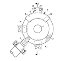
- the plate-shaped fan-shaped permanent magnet 5 is fixed to the housing 6 on the right side in the drawing via the support A so that the fan-shaped flat surface facing the tooth surface 3a of the permanent magnet 5 is not rotated.
- the lubricating magnetic fluid L is held by a magnetic force, and the permanent magnet 5 is disposed close to the tooth surface 3a of the large-diameter bevel gear 3 so that the lubricating magnetic fluid L touches the tooth surface 3a.
- the rotary shaft 4 of the large-diameter bevel gear 3 is rotatably supported by a housing 6 made of metal or the like via a pair of rolling bearings 7.
- the support A fixed to the housing 6 on the right side in the figure has a fan-shaped top plate 8 that covers the back of the fan-shaped permanent magnet 5 and a central portion at a height that exceeds the axial thickness of the large-diameter bevel gear 3.
- a peripheral wall 9 to be supported and a flange 11 for mounting the fixing bolt 10 are provided.
- the fan-shaped permanent magnet 5 is fitted inside the fan-shaped top plate 8 and fitted to the bottom of the two standing walls 12 provided in the circumferential direction, and appropriately fixed by adhesion or the like.
- At least one permanent magnet 5 fixed by the support A may be provided so that the permanent magnet 5 faces the tooth surface 3a at a predetermined position of the large-diameter bevel gear 3, but in FIG.
- a plurality of supports A1 and A2 may be provided such that the meshing position with the small-diameter bevel gear (pinion) 2 is centered and the left and right sides are paired. If a plurality of permanent magnets 5 are provided as shown in the drawing, the lubricating magnetic fluid L can be evenly supplied under the same conditions regardless of the rotation direction of the large-diameter bevel gear 3.
- the shape of the permanent magnet may be a shape that efficiently covers the tooth surface in as small an area as possible according to the type and shape of the large-diameter gear such as the large-diameter bevel gear 3.
- a fan-shaped, rectangular, or other polygonal plate And a well-known shape such as a circular groove shape covering the tooth surface or a circular curved plate shape.
- the molding material for permanent magnets is a mixture of neodymium, ferrite and other magnet powder containing a binder resin and reinforcing fibers such as glass wire, and is molded by a well-known manufacturing method for bond magnets and plastic magnets (also called plastic magnets). it can.
- a coil is wound around a core material made of a separately provided magnetic material and energized when the gear mechanism is driven. It may be a magnet that generates a magnetic force.
- the lubricating magnetic fluid L is a lubricating magnetic fluid in which fine particles of a magnetic material are dispersed by blending a surfactant in lubricating oil or lubricating grease, and well-known techniques can be used for the components and manufacturing method thereof.
- ferromagnetic fine particles such as magnetite, manganese ferrite, manganese zinc ferrite, and cobalt ferrite can be used as the fine-particle magnetic material.
- Lubricating magnetic fluids include a surfactant that covers the surface of such ferromagnetic fine particles in advance before being oxidized in the air, and a base oil (lubricating oil) such as mineral oil or synthetic oil as a lubricating component, or such It is a magnetic colloid solution made of an oil obtained by adding an additive such as an extreme pressure agent to a natural base oil or a lubricating grease.
- a base oil lubricating oil
- mineral oil or synthetic oil as a lubricating component
- Such a lubricating magnetic fluid L holds an appropriate amount by the magnetic force on the surface facing the tooth surface 3a of the permanent magnet 5 when assembling the speed reducer.
- the viscosity is changed and held in an aggregated state.
- the permanent magnet 5 in which N and S poles are arranged along the tooth width direction of the large-diameter gear is employed. It flows in the width direction of the surface, and most of the tooth surface becomes wet easily.
- the supply amount of the lubricating magnetic fluid L at the time of assembling the reduction gear is an appropriate amount so that an interface is formed so that the lubricating magnetic fluid L is in contact with or buried in the tooth surface of the rotating large-diameter gear.
- the holding amount is also adjusted according to the set distance between the permanent magnet and the tooth surface of the large-diameter gear.
- the rotational force of the small-diameter bevel gear 2 is transmitted to the large-diameter bevel gear 3, and centrifugal force acts on the decelerated large-diameter bevel gear 3. Since the liquid surface of the lubricating magnetic fluid L on the permanent magnet 5 fixed and held so as not to touch is touched, a necessary and sufficient amount of lubricating oil adheres to the large-diameter bevel gear 3 that rotates at a low speed.
- the large-diameter bevel gear 3 and the small-diameter bevel gear 2 can have a stable lubricity and a lubricating oil cooling function.
- FIGS. 3 and 4A A second embodiment of the present invention will be described below.
- the reduction gear of the second embodiment of the present invention shown in FIGS. 3 and 4A employs a planetary gear mechanism as the reduction gear mechanism of the first embodiment described above.
- This reduction device includes a sun gear 21 that is a small-diameter gear provided at one end of an input shaft 20, an internal gear 22 that is a large-diameter gear arranged around the sun gear 21, a sun gear 21 and an internal gear.
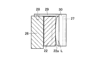
- the plate-shaped permanent magnet 27 comprises a housing 26 that rotatably holds the internal gear 22 described above, and a bolt 28 is attached to the housing 26 via a thin box-shaped holder 30 with a support arm 29 held on the inner bottom. It is fixed by a stop.
- the lubricating magnetic fluid L has an appropriate amount of magnetic force retained on the surface of the permanent magnet 27 facing the tooth surface 22a of the internal gear 22 when the speed reducer is assembled.
- the length of the support arm 29 is adjusted so that the lubricating magnetic fluid L touches the tooth surface 22a of the internal gear 22, and the permanent magnet 27 is brought closer to the tooth surface 22a of the internal gear 22. Provided in position.
- the lubricating magnetic fluid L attached to the permanent magnet 27 fixed to the housing 26 is centrifuged against the tooth surface 22a of the internal gear 22 decelerated with respect to the rotational speed of the sun gear 21. Since the tooth surface 22a is quietly contacted when no force is applied, a necessary and sufficient amount of lubricating oil adheres and does not scatter.
- the third embodiment of the present invention replaces the thin box holder 30 with the support arm 29 that is fixed to the housing 26 by bolting in the second embodiment described above.
- the plate-shaped permanent magnet 27 is held by a thin box-shaped holder 30 with an L-shaped plate-shaped support arm 31 that is fixed to the carrier 25 by bolting, and the other configuration is the second embodiment.
- the form is exactly the same.
- the thin box-shaped holder 30 with the plate-shaped support arm 31 is fixed to the carrier 25 that is stationary and non-rotating around the axis of the internal gear 22.
- the held lubricating magnetic fluid L on the permanent magnet 27 touches the tooth surface 22a of the internal gear 22 in a state where the centrifugal force does not act, and a necessary and sufficient amount of lubricating oil adheres and does not scatter.
- an appropriate amount of lubricating oil is not scattered by centrifugal force, and an appropriate amount of lubricating oil that is transferred to the internal gear 22, the planetary gear 23, and the sun gear 21 in order.
- a stable lubricating property and a cooling function of the lubricating oil can be exerted by the lubricating oil of the magnetic ferrofluid.
Landscapes
- Engineering & Computer Science (AREA)
- General Engineering & Computer Science (AREA)
- Mechanical Engineering (AREA)
- General Details Of Gearings (AREA)
- Gear Transmission (AREA)
- Retarders (AREA)
Abstract
回転する入力軸(1)から小径傘歯車2に入力された回転力を大径傘歯車(3)に伝導し、大径傘歯車(3)から減速された回転力を出力軸(4)に出力する減速歯車機構を有する減速機であり、回転する大径傘歯車(3)の歯面(3a)に向き合って、この大径傘歯車(3)の軸回りに非回転であるように、板状で扇形の永久磁石(5)をハウジング(6)に固定して設け、この永久磁石(5)の歯面(3a)に対向する扇形の平面に潤滑性磁性流体(L)を磁力で保持して設け、この潤滑性磁性流体Lが歯面(3a)に触れるように、永久磁石(5)を大径傘歯車(3)の歯面(3a)に近づけて配置した減速機とする。
Description
この発明は、潤滑性の改善された歯車機構を有する減速機に関するものである。
一般に、小径歯車に入力された回転力を大径歯車に伝導し、この大径歯車から減速された回転力を出力する減速歯車機構は周知であり、遊星歯車機構のような減速歯車機構は、減速機に用いられている。
減速機の歯車同士の噛み合い部分には、グリース潤滑法、油浴式潤滑法、ポンプによる滴下、噴射、噴霧によって強制的に潤滑油を供給することにより、噛み合う歯面間の動摩擦係数を低減し、かつ歯車を冷却することが求められる。
例えば、減速機の歯車機構に対する潤滑装置として、遊星歯車の転がり軸受上方に給油ノズルを固定して、自転しつつ公転する遊星歯車の前記転がり軸受の軸方向上方から下向きに潤滑油を供給する潤滑装置が周知である。
このような潤滑装置には、遊星歯車が公転しているときに、給油ノズルから軸受上に供給された潤滑油が、公転する遊星歯車に作用する遠心力で径方向外方にはね飛ばされるので、潤滑油が軸受内部に流入し難く不足しがちであり、転がり軸受や遊星歯車機構の潤滑が充分にできないという問題がある。
減速機等の潤滑不足を改善し、給油量を効率よく利用するために、遠心力の作用する方向からずれた位置に潤滑油量を確保し、遊星歯車の転がり軸受の潤滑を充分にすることが知られている(下記特許文献1)。
また、磁性材料からなる微粒子が分散した潤滑油を用いて転がり軸受を潤滑する際に、保持器の一部をシート状の永久磁石または磁性微粒子を含む塗料で形成し、保持器の要部に磁性流体の潤滑油を吸着させて、軸受の回転性能を向上させることが知られている(下記特許文献2)。
しかし、減速機の歯車の刃面部分に潤滑剤の充分な保持機能をもたせることは難しく、例えば、歯車の歯面に磁性を持たせたとしても、歯車が高速回転するときの強い遠心力によって、安定した潤滑性が得られない。
また、潤滑油を飛散防止するために高粘度油を採用すると、歯車の回転抵抗が大きくなるので、それでは減速機の効率が低下し、歯車機構に安定した回転性能は望めない。
そこで、この発明の課題は、上記した問題点を解決し、減速機に用いられる歯車機構における潤滑性を高めると共に、歯車の回転性能を損なわないようにし、特に潤滑油が飛散せず、しかも歯車が常時安定した潤滑性や冷却機能を有する減速機とすることである。
上記の課題を解決するために、この発明においては、小径歯車に入力された回転力を大径歯車に伝導し、この大径歯車から減速された回転力を出力する減速歯車機構を有する減速機において、回転する前記大径歯車の歯面に向き合ってこの大径歯車の軸回りに非回転であるように磁石をハウジングまたは歯車の支持部品に固定して設け、この磁石の前記歯面に対向する面に潤滑性磁性流体を磁力で保持して設け、この潤滑性磁性流体が前記歯面に触れるように前記磁石を前記大径歯車の歯面に近づけて配置したことを特徴とする減速機としたのである。
上記したように構成されるこの発明の減速機は、小径歯車に入力された回転力を大径歯車に伝導し、この大径歯車が回転する際に、この歯面に向き合って磁石の対向面に磁力で保持されている潤滑性磁性流体が、前記大径歯車の歯面に触れ、このとき永久磁石が歯車軸回りに非回転であるので、潤滑性磁性流体に遠心力が作用せずに飛び散ることなく保持されており、また安定的に前記歯面に触れ、さらに大径歯車から小径歯車にまで移乗し、減速歯車機構の全体は潤滑性磁性流体によって潤滑される。
上記磁石は、永久磁石または電磁石のいずれであっても良いが、前記大径歯車の歯幅方向に沿ってN・S極を配置した磁石であることが、潤滑性磁性流体を、大径歯車の歯溝に沿って歯面の幅方向に流れ込みやすくし、歯面全体が濡れやすいので好ましい。
また、上記潤滑性磁性流体が、微粒子状の磁性体を潤滑油または潤滑グリースに分散させた潤滑性磁性流体であることにより、磁性流体は磁石面に保持されやすく、減速歯車機構全体をより確実に潤滑できる。
また、上記減速歯車機構は、小径歯車に入力された回転力を直接に大径歯車に伝導する減速歯車機構ばかりでなく、小径歯車に入力された回転力を遊星歯車を介して間接的に大径歯車に伝導する遊星歯車機構であってもよく、その場合にも、上記同様に潤滑性磁性流体は、飛散せず減速機に常に安定した潤滑性や冷却性を与える作用がある。
前記大径歯車の歯面に向き合って静止するように磁石をハウジングまたは静止した部品に固定するには、上記静止した部品として、遊星歯車のキャリアを用いることができる。遊星歯車のキャリアは、複数の遊星歯車同士の間隔を保ちながら各遊星歯車の自転を回転自在に保持するものであり、大径歯車の歯面に向き合ってこの歯車の軸回りに非回転であり、回転する大径歯車の軸回りに静止した部品である。
この発明は、減速歯車機構を有する減速機における回転する前記大径歯車の歯面に向き合わせて、磁石を固定し、その所定面に潤滑性磁性流体を磁力で保持し前記歯面に触れるように配置したので、潤滑油が飛散するような遠心力を受けず、また歯車に安定した潤滑性や冷却機能を作用させることができる減速機となる利点がある。
この発明の実施形態を以下に添付図面に基づいて説明する。
図1、2に示すように、第1実施形態は、電動モーターなどにより回転する入力軸1から小径傘歯車(ピニオン)2に入力された回転力を大径傘歯車3に伝導し、大径傘歯車3から減速された回転力を出力軸4に出力する減速歯車機構を有する減速機であり、回転する大径傘歯車3の歯面3aに向き合って、この大径傘歯車3の軸回りに非回転であるように、板状で扇形の永久磁石5を支持具Aを介して図中右側のハウジング6に固定して設け、永久磁石5の歯面3aに対向する扇形の平面には、潤滑性磁性流体Lを磁力で保持し、この潤滑性磁性流体Lが歯面3aに触れるように、永久磁石5を大径傘歯車3の歯面3aに近づけて配置した減速機である。
図1、2に示すように、第1実施形態は、電動モーターなどにより回転する入力軸1から小径傘歯車(ピニオン)2に入力された回転力を大径傘歯車3に伝導し、大径傘歯車3から減速された回転力を出力軸4に出力する減速歯車機構を有する減速機であり、回転する大径傘歯車3の歯面3aに向き合って、この大径傘歯車3の軸回りに非回転であるように、板状で扇形の永久磁石5を支持具Aを介して図中右側のハウジング6に固定して設け、永久磁石5の歯面3aに対向する扇形の平面には、潤滑性磁性流体Lを磁力で保持し、この潤滑性磁性流体Lが歯面3aに触れるように、永久磁石5を大径傘歯車3の歯面3aに近づけて配置した減速機である。
大径傘歯車3の回転軸4は、1対の転がり軸受7を介して金属等からなるハウジング6に回転自在に支持されている。図中右側のハウジング6に固定された支持具Aは、扇形の永久磁石5の背面を覆う扇状の天板8と、その中央部分を大径傘歯車3の軸方向の厚みを超える高さで支える周壁9および固定用ボルト10の取付用のフランジ11を有している。また、扇形の永久磁石5は、扇状の天板8の内側に、周方向に設けた2条の立壁12の底部に嵌め、また適宜に接着等により固定して取り付けられている。
上記したように支持具Aで固定される永久磁石5は、大径傘歯車3の所定位置の歯面3aに永久磁石5が向き合うように少なくとも1つ設ければよいが、また図2中に一点鎖線で示すように、小径傘歯車(ピニオン)2との噛み合わせ位置を中央にして、その左右両側に対にするなど、複数の支持具A1,A2を設けても良い。図示したように複数の永久磁石5を設ければ、大径傘歯車3の回転方向に拘わらず、潤滑性磁性流体Lを同じ条件で均等に供給することができる。
永久磁石の形状は、大径傘歯車3等の大径歯車の種類と形状に合わせて、できるだけ小面積で効率よく歯面を覆う形状であれば良く、例えば扇形、長方形その他の多角形の板状、歯面を覆うような円溝状等や円曲面板状など、周知形状に設けることができる。
永久磁石の成形材料は、ネオジム、フェライト等の磁石粉末に、バインダ用樹脂と、ガラス線などの強化繊維を含む混合物を用い、ボンド磁石やプラスチックマグネット(プラマグとも称される)の周知製法で成形できる。
また、永久磁石に代えて、電磁石を用いることも可能であり、別途設けた磁性材料からなる芯素材のまわりに、コイルを巻いて歯車機構の駆動時に通電することによって、必要に応じて一時的に磁力を発生させる磁石であっても良い。
潤滑性磁性流体Lは、微粒子状の磁性体を潤滑油または潤滑グリースに界面活性剤を配合して分散させた潤滑性磁性流体であり、その成分や製法は周知技術を採用できる。
因みに、微粒子状の磁性体は、マグネタイト、マンガンフェライト、マンガン亜鉛フェライト、コバルトフェライトなどの強磁性微粒子を用いることができる。
因みに、微粒子状の磁性体は、マグネタイト、マンガンフェライト、マンガン亜鉛フェライト、コバルトフェライトなどの強磁性微粒子を用いることができる。
潤滑性磁性流体は、このような強磁性微粒子表面を空気中で酸化する前に予め覆っておく界面活性剤と、潤滑成分である鉱油、合成油等の基油(潤滑油)、またはこのような基油に極圧剤などの添加剤を加えた油又は潤滑グリース等からなる磁性コロイド溶液である。
このような潤滑性磁性流体Lは、減速機を組み立てる際に、前記した永久磁石5の歯面3aに対向する面に磁力で適量を保持させておくが、その際、磁場中で見かけ上の粘度が変化して集合した状態で保持される。
第一実施形態では、大径歯車の歯幅方向に沿ってN・S極を配置した永久磁石5を採用しており、歯面に触れて流動すると、大径歯車の歯溝に沿って歯面の幅方向に流動し、歯面の大部分が濡れやすくなる。
減速装置の組み立て当初の潤滑性磁性流体Lの供給量は、潤滑性磁性流体Lが回転する大径歯車の歯面に、接するかまたは埋没して触れるような界面が形成されるように、適量を保持させればよく、保持量は、永久磁石との大径歯車の歯面との設定距離に応じても調整する。
このようにして構成される第1実施形態の減速機は、小径傘歯車2の回転力を大径傘歯車3に伝導して、減速された大径傘歯車3に対して、遠心力が作用しないように固定されて保持された永久磁石5上の潤滑性磁性流体Lの液面に触れさせるので、低速回転する大径傘歯車3には必要かつ十分な量の潤滑油が付着する。
そのため、潤滑に作用する適量の潤滑油が大きな遠心力を受けずに飛散しない。また大径傘歯車3および小径傘歯車2には、安定した潤滑性と潤滑油の冷却機能を作用させることができる。
この発明の第2実施形態について、以下に説明する。
図3、図4Aに示すこの発明の第2実施形態の減速機は、上記した第1実施形態の減速歯車機構として、遊星歯車機構を採用したものである。
図3、図4Aに示すこの発明の第2実施形態の減速機は、上記した第1実施形態の減速歯車機構として、遊星歯車機構を採用したものである。
この減速機は、入力軸20の一端に設けられた小径歯車である太陽歯車21と、その周りに同芯状態に配置された大径歯車である内歯歯車22と、太陽歯車21と内歯歯車22との間に介在する3つの遊星歯車23と、これら3つの遊星歯車23をそれぞれ支持する支持軸24と、これら3つの支持軸24を回転自在に支持しつつ連結する環状のキャリア25と、前記した内歯歯車22を回転自在に保持するハウジング26からなり、板状の永久磁石27は、内側底部に保持する支持アーム29付きの薄箱形ホルダ30を介して、ハウジング26にボルト28止めにより固定して設けたものである。
このような減速機においても、前記同様に潤滑性磁性流体Lは、減速機を組み立てる際に、前記した永久磁石27の内歯歯車22の歯面22aに対向する面に磁力で適量を保持させており、潤滑性磁性流体Lが、内歯歯車22の歯面22aに触れるように、支持アーム29の長さを調節して、永久磁石27を内歯歯車22の歯面22aに接近させた位置に設けている。
第2実施形態においては、太陽歯車21の回転速度に対して減速された内歯歯車22の歯面22aに対し、ハウジング26に固定された永久磁石27に付着する潤滑性磁性流体Lが、遠心力の作用しない状態で歯面22aに静かに接触するので、必要かつ十分な量の潤滑油が付着して飛散しない。
また、図3、図4Bに示すこの発明の第3実施形態は、上記した第2実施形態において、ハウジング26にボルト止めにより固定して設けた支持アーム29付きの薄箱形ホルダ30に代えて、キャリア25にボルト止めにより固定して設けられるL字型板状の支持アーム31付きの薄箱形ホルダ30で板状の永久磁石27を保持したものであり、その他の構成は、第2実施形態と全く同様である。
第3実施形態における字型板状の支持アーム31付きの薄箱形ホルダ30は、内歯歯車22の軸回りに非回転で静止するキャリア25に固定されているので、薄箱形ホルダ30に保持された永久磁石27上の潤滑性磁性流体Lは、遠心力の作用しない状態で内歯歯車22の歯面22aに触れて、必要かつ十分な量の潤滑油が付着して飛散しない。
このようにして、第2、第3の実施形態においても、適量の潤滑油は遠心力で飛散せず、また内歯歯車22、遊星歯車23および太陽歯車21には、順に移乗する適量の潤滑性磁性流体の潤滑油によって、安定した潤滑性と潤滑油の冷却機能を作用させることができる。
1、20 入力軸
2 小径傘歯車
3 大径傘歯車
3a 歯面
4 出力軸
5、27 永久磁石
5a 平面
6、26 ハウジング
7 転がり軸受
8 天板
9 周壁
10、28 ボルト
11 フランジ
12 立壁
21 太陽歯車
22 内歯歯車
23 遊星歯車
24 支持軸
25 キャリア
29、31 支持アーム
30 薄箱形ホルダ
L 潤滑性磁性流体
A,A1,A2 支持具
2 小径傘歯車
3 大径傘歯車
3a 歯面
4 出力軸
5、27 永久磁石
5a 平面
6、26 ハウジング
7 転がり軸受
8 天板
9 周壁
10、28 ボルト
11 フランジ
12 立壁
21 太陽歯車
22 内歯歯車
23 遊星歯車
24 支持軸
25 キャリア
29、31 支持アーム
30 薄箱形ホルダ
L 潤滑性磁性流体
A,A1,A2 支持具
Claims (5)
- 小径歯車に入力された回転力を大径歯車に伝導し、この大径歯車から減速された回転力を出力する減速歯車機構を有する減速機において、
回転する前記大径歯車の歯面に向き合ってこの大径歯車の軸回りに非回転であるように磁石をハウジングまたは歯車の支持部品に固定して設け、この磁石の前記歯面に対向する面に潤滑性磁性流体を磁力で保持して設け、この潤滑性磁性流体が前記歯面に触れるように前記磁石を前記大径歯車の歯面に近づけて配置したことを特徴とする減速機。 - 上記磁石は、前記大径歯車の歯幅方向に沿ってN・S極を配置した磁石である請求項1に記載の減速機。
- 上記潤滑性磁性流体が、微粒子状の磁性体を潤滑油または潤滑グリースに分散させた潤滑性磁性流体である請求項1または2に記載の減速機。
- 上記減速歯車機構が、遊星歯車機構である請求項1~3のいずれかに記載の減速機。
- 上記歯車の支持部品が、遊星歯車のキャリアである請求項4に記載の減速機。
Applications Claiming Priority (2)
| Application Number | Priority Date | Filing Date | Title |
|---|---|---|---|
| JP2015136772A JP2017020539A (ja) | 2015-07-08 | 2015-07-08 | 減速機 |
| JP2015-136772 | 2015-07-08 |
Publications (1)
| Publication Number | Publication Date |
|---|---|
| WO2017006987A1 true WO2017006987A1 (ja) | 2017-01-12 |
Family
ID=57685639
Family Applications (1)
| Application Number | Title | Priority Date | Filing Date |
|---|---|---|---|
| PCT/JP2016/070113 Ceased WO2017006987A1 (ja) | 2015-07-08 | 2016-07-07 | 減速機 |
Country Status (2)
| Country | Link |
|---|---|
| JP (1) | JP2017020539A (ja) |
| WO (1) | WO2017006987A1 (ja) |
Families Citing this family (1)
| Publication number | Priority date | Publication date | Assignee | Title |
|---|---|---|---|---|
| JP7500245B2 (ja) * | 2019-04-25 | 2024-06-17 | 日鉄鉱業株式会社 | コバルトフェライト粒子の製造方法とそれにより製造されたコバルトフェライト粒子 |
Citations (3)
| Publication number | Priority date | Publication date | Assignee | Title |
|---|---|---|---|---|
| JPS57160448U (ja) * | 1982-01-14 | 1982-10-08 | ||
| JPH0257794A (ja) * | 1988-08-18 | 1990-02-27 | Tokin Corp | 駆動機構の潤滑方法 |
| JPH0533848A (ja) * | 1991-07-31 | 1993-02-09 | Osaka Gas Co Ltd | ギヤ伝動機構のオイル切れ防止構造 |
Family Cites Families (2)
| Publication number | Priority date | Publication date | Assignee | Title |
|---|---|---|---|---|
| JP2003063424A (ja) * | 2001-08-28 | 2003-03-05 | Nsk Ltd | 電動パワーステアリング装置 |
| JP2009057996A (ja) * | 2007-08-30 | 2009-03-19 | Nachi Fujikoshi Corp | 遊星歯車式減速機付油圧モータ |
-
2015
- 2015-07-08 JP JP2015136772A patent/JP2017020539A/ja active Pending
-
2016
- 2016-07-07 WO PCT/JP2016/070113 patent/WO2017006987A1/ja not_active Ceased
Patent Citations (3)
| Publication number | Priority date | Publication date | Assignee | Title |
|---|---|---|---|---|
| JPS57160448U (ja) * | 1982-01-14 | 1982-10-08 | ||
| JPH0257794A (ja) * | 1988-08-18 | 1990-02-27 | Tokin Corp | 駆動機構の潤滑方法 |
| JPH0533848A (ja) * | 1991-07-31 | 1993-02-09 | Osaka Gas Co Ltd | ギヤ伝動機構のオイル切れ防止構造 |
Also Published As
| Publication number | Publication date |
|---|---|
| JP2017020539A (ja) | 2017-01-26 |
Similar Documents
| Publication | Publication Date | Title |
|---|---|---|
| KR101622020B1 (ko) | 아우터 로터 타입 모터, 이를 이용한 냉기 순환 팬 및 이를 이용한 냉장고 | |
| JP6638444B2 (ja) | 真空ポンプ | |
| IN2014CN03044A (ja) | ||
| CN203104177U (zh) | 旋转电机 | |
| CN103185075A (zh) | 用于润滑轴承的组件 | |
| EP3220519A1 (en) | Motor with deceleration mechanism | |
| JP2016197930A (ja) | ブラシ付きモータ | |
| CN115549344A (zh) | 驱动装置、车辆 | |
| CN106416012B (zh) | 旋转致动器 | |
| WO2017006987A1 (ja) | 減速機 | |
| JP2006112627A (ja) | スピンドルの油維持構造 | |
| US10124282B2 (en) | Filter device | |
| JP2011174559A (ja) | 回転伝達ギヤ及び駆動装置 | |
| CN101911439A (zh) | 电动机 | |
| CN202266675U (zh) | 拉丝机密封装置 | |
| JP2010133545A (ja) | 遊星ローラ式動力伝達装置 | |
| JPH06207616A (ja) | 磁性流体軸受装置 | |
| CN211377773U (zh) | 电动机 | |
| US20140287865A1 (en) | Rotating electric machine | |
| JP2006214505A (ja) | 円錐ころ軸受装置および車両用ピニオン軸支持装置 | |
| JP6208073B2 (ja) | 遊星歯車減速装置、及びこれを備えたスタータ | |
| CN203441991U (zh) | 转动组件及具有其的搅拌器 | |
| JP2012177430A (ja) | 電気自動車用モータ付き減速差動装置 | |
| CN104115375A (zh) | 电动机 | |
| JP2016208603A5 (ja) |
Legal Events
| Date | Code | Title | Description |
|---|---|---|---|
| 121 | Ep: the epo has been informed by wipo that ep was designated in this application |
Ref document number: 16821455 Country of ref document: EP Kind code of ref document: A1 |
|
| NENP | Non-entry into the national phase |
Ref country code: DE |
|
| 122 | Ep: pct application non-entry in european phase |
Ref document number: 16821455 Country of ref document: EP Kind code of ref document: A1 |