WO2017006971A1 - 燃焼器及びガスタービン - Google Patents
燃焼器及びガスタービン Download PDFInfo
- Publication number
- WO2017006971A1 WO2017006971A1 PCT/JP2016/070051 JP2016070051W WO2017006971A1 WO 2017006971 A1 WO2017006971 A1 WO 2017006971A1 JP 2016070051 W JP2016070051 W JP 2016070051W WO 2017006971 A1 WO2017006971 A1 WO 2017006971A1
- Authority
- WO
- WIPO (PCT)
- Prior art keywords
- combustion cylinder
- space
- acoustic device
- wall
- combustor
- Prior art date
- Legal status (The legal status is an assumption and is not a legal conclusion. Google has not performed a legal analysis and makes no representation as to the accuracy of the status listed.)
- Ceased
Links
Images





Classifications
-
- F—MECHANICAL ENGINEERING; LIGHTING; HEATING; WEAPONS; BLASTING
- F23—COMBUSTION APPARATUS; COMBUSTION PROCESSES
- F23R—GENERATING COMBUSTION PRODUCTS OF HIGH PRESSURE OR HIGH VELOCITY, e.g. GAS-TURBINE COMBUSTION CHAMBERS
- F23R3/00—Continuous combustion chambers using liquid or gaseous fuel
- F23R3/42—Continuous combustion chambers using liquid or gaseous fuel characterised by the arrangement or form of the flame tubes or combustion chambers
- F23R3/46—Combustion chambers comprising an annular arrangement of several essentially tubular flame tubes within a common annular casing or within individual casings
-
- F—MECHANICAL ENGINEERING; LIGHTING; HEATING; WEAPONS; BLASTING
- F23—COMBUSTION APPARATUS; COMBUSTION PROCESSES
- F23R—GENERATING COMBUSTION PRODUCTS OF HIGH PRESSURE OR HIGH VELOCITY, e.g. GAS-TURBINE COMBUSTION CHAMBERS
- F23R3/00—Continuous combustion chambers using liquid or gaseous fuel
- F23R3/42—Continuous combustion chambers using liquid or gaseous fuel characterised by the arrangement or form of the flame tubes or combustion chambers
-
- F—MECHANICAL ENGINEERING; LIGHTING; HEATING; WEAPONS; BLASTING
- F23—COMBUSTION APPARATUS; COMBUSTION PROCESSES
- F23R—GENERATING COMBUSTION PRODUCTS OF HIGH PRESSURE OR HIGH VELOCITY, e.g. GAS-TURBINE COMBUSTION CHAMBERS
- F23R3/00—Continuous combustion chambers using liquid or gaseous fuel
- F23R3/002—Wall structures
-
- F—MECHANICAL ENGINEERING; LIGHTING; HEATING; WEAPONS; BLASTING
- F02—COMBUSTION ENGINES; HOT-GAS OR COMBUSTION-PRODUCT ENGINE PLANTS
- F02C—GAS-TURBINE PLANTS; AIR INTAKES FOR JET-PROPULSION PLANTS; CONTROLLING FUEL SUPPLY IN AIR-BREATHING JET-PROPULSION PLANTS
- F02C3/00—Gas-turbine plants characterised by the use of combustion products as the working fluid
- F02C3/04—Gas-turbine plants characterised by the use of combustion products as the working fluid having a turbine driving a compressor
-
- F—MECHANICAL ENGINEERING; LIGHTING; HEATING; WEAPONS; BLASTING
- F23—COMBUSTION APPARATUS; COMBUSTION PROCESSES
- F23R—GENERATING COMBUSTION PRODUCTS OF HIGH PRESSURE OR HIGH VELOCITY, e.g. GAS-TURBINE COMBUSTION CHAMBERS
- F23R3/00—Continuous combustion chambers using liquid or gaseous fuel
- F23R3/02—Continuous combustion chambers using liquid or gaseous fuel characterised by the air-flow or gas-flow configuration
- F23R3/16—Continuous combustion chambers using liquid or gaseous fuel characterised by the air-flow or gas-flow configuration with devices inside the flame tube or the combustion chamber to influence the air or gas flow
- F23R3/18—Flame stabilising means, e.g. flame holders for after-burners of jet-propulsion plants
-
- F—MECHANICAL ENGINEERING; LIGHTING; HEATING; WEAPONS; BLASTING
- F23—COMBUSTION APPARATUS; COMBUSTION PROCESSES
- F23R—GENERATING COMBUSTION PRODUCTS OF HIGH PRESSURE OR HIGH VELOCITY, e.g. GAS-TURBINE COMBUSTION CHAMBERS
- F23R3/00—Continuous combustion chambers using liquid or gaseous fuel
- F23R3/28—Continuous combustion chambers using liquid or gaseous fuel characterised by the fuel supply
-
- G—PHYSICS
- G10—MUSICAL INSTRUMENTS; ACOUSTICS
- G10K—SOUND-PRODUCING DEVICES; METHODS OR DEVICES FOR PROTECTING AGAINST, OR FOR DAMPING, NOISE OR OTHER ACOUSTIC WAVES IN GENERAL; ACOUSTICS NOT OTHERWISE PROVIDED FOR
- G10K11/00—Methods or devices for transmitting, conducting or directing sound in general; Methods or devices for protecting against, or for damping, noise or other acoustic waves in general
- G10K11/16—Methods or devices for protecting against, or for damping, noise or other acoustic waves in general
- G10K11/162—Selection of materials
-
- F—MECHANICAL ENGINEERING; LIGHTING; HEATING; WEAPONS; BLASTING
- F05—INDEXING SCHEMES RELATING TO ENGINES OR PUMPS IN VARIOUS SUBCLASSES OF CLASSES F01-F04
- F05D—INDEXING SCHEME FOR ASPECTS RELATING TO NON-POSITIVE-DISPLACEMENT MACHINES OR ENGINES, GAS-TURBINES OR JET-PROPULSION PLANTS
- F05D2240/00—Components
- F05D2240/35—Combustors or associated equipment
-
- F—MECHANICAL ENGINEERING; LIGHTING; HEATING; WEAPONS; BLASTING
- F23—COMBUSTION APPARATUS; COMBUSTION PROCESSES
- F23R—GENERATING COMBUSTION PRODUCTS OF HIGH PRESSURE OR HIGH VELOCITY, e.g. GAS-TURBINE COMBUSTION CHAMBERS
- F23R2900/00—Special features of, or arrangements for continuous combustion chambers; Combustion processes therefor
- F23R2900/00013—Reducing thermo-acoustic vibrations by active means
-
- F—MECHANICAL ENGINEERING; LIGHTING; HEATING; WEAPONS; BLASTING
- F23—COMBUSTION APPARATUS; COMBUSTION PROCESSES
- F23R—GENERATING COMBUSTION PRODUCTS OF HIGH PRESSURE OR HIGH VELOCITY, e.g. GAS-TURBINE COMBUSTION CHAMBERS
- F23R2900/00—Special features of, or arrangements for continuous combustion chambers; Combustion processes therefor
- F23R2900/00014—Reducing thermo-acoustic vibrations by passive means, e.g. by Helmholtz resonators
Definitions
- This disclosure relates to combustors and gas turbines.
- the gas turbine has a combustor and a turbine, and the turbine generates a rotational force by using combustion gas generated by burning the fuel by the combustor.
- An acoustic device combustion vibration reducing device
- the acoustic liner can dampen combustion vibration of a predetermined frequency caused by coupling of an acoustic mode and a combustion system.
- the acoustic liner disclosed in Patent Document 1 defines a gas space that communicates with the inside of the transition piece of the combustor via a vent hole, and can dampen combustion vibration at a predetermined frequency.
- acoustic liners are designed to have a single tuning frequency and can dampen combustion vibrations at and near the tuning frequency.
- combustion vibration a plurality of modes (combustion vibration modes) having significantly different frequencies may occur due to various factors such as a combustion state.
- combustion vibration modes In the operation of the gas turbine, it is preferable that more combustion vibration modes can be damped.
- a combustion vibration mode whose frequency is greatly different from that of the tuning frequency, it cannot be damped by one acoustic liner.
- an object of at least one embodiment of the present invention is to provide a combustor and a gas turbine including an acoustic device capable of damping a plurality of combustion vibration modes.
- a combustor includes: A combustion cylinder having a first region in which at least one first opening is formed; A nozzle configured to inject fuel into the combustion cylinder; A first acoustic device attached to the combustion cylinder; With The first acoustic device includes: The first region and the at least one first wall have at least one first wall disposed opposite to the first region and having at least one second opening formed outside the combustion cylinder.
- a first casing portion defining at least one first space communicating with the interior of the combustion cylinder through the at least one first opening It has at least 1 2nd wall arrange
- the first acoustic device has a plurality of tuning frequencies because the second space communicating with the first space through the first opening exists outside the first space. For this reason, a plurality of combustion vibration modes having different frequencies can be attenuated by the first acoustic device.
- the at least one first opening and the at least one second opening are at the same or different positions in the axial direction of the combustion cylinder.
- the at least one second space includes a plurality of second spaces separated from each other by partition walls and having different heights in the radial direction of the combustion cylinder.
- the plurality of second spaces separated by the partition walls have different heights, so that the first acoustic device can have more tuning frequencies. For this reason, more combustion vibration modes can be attenuated by the first acoustic device.
- the plurality of second spaces are arranged along the circumferential direction of the combustion cylinder.
- a plurality of second spaces having different heights can be provided with a simple configuration. .
- the plurality of second spaces are arranged along the axial direction of the combustion cylinder.
- the plurality of second spaces having different heights can be provided with a simple configuration. .
- the heights of the plurality of second spaces are gradually reduced as they approach the nozzle in the axial direction of the combustion cylinder.
- a combustion vibration mode having a high frequency is generated as compared with a region far from the flame.
- the height of the second space gradually decreases as it approaches the nozzle in the axial direction of the combustion cylinder, and the high frequency near the flame is high.
- the combustion vibration mode can be damped.
- the first acoustic device is disposed within a range corresponding to the inner diameter of the combustion cylinder from the tip of the nozzle in the axial direction of the combustion cylinder.
- the first acoustic device is installed in a range corresponding to the inner diameter of the combustion cylinder in the axial direction of the combustion cylinder, so that a large number of combustion vibration modes are provided. It can be effectively attenuated.
- a second acoustic device attached to the combustor The combustion cylinder further includes a second region in which at least one third opening is formed, The second acoustic device has a third wall disposed on the outer side of the combustion cylinder so as to face the second region, and the at least one third wall is provided between the second region and the third wall. At least one third space communicating with the inside of the combustion cylinder through the opening is defined.
- the first acoustic device has a tuning frequency corresponding to the height of the first space, and a tuning frequency corresponding to the sum of the height of the first space and the height of the second space.
- the second acoustic device has a tuning frequency corresponding to the height of the third space, and the tuning frequency of the second acoustic device is located between the two frequencies of the first acoustic device. For this reason, the combustion vibration mode can be damped continuously over a wide frequency range.
- the first acoustic device is arranged closer to the nozzle than the second acoustic device in the axial direction of the combustion cylinder.
- the closer to the nozzle the more the combustion vibration modes tend to occur.
- the first acoustic device is disposed closer to the nozzle than the second acoustic device in the axial direction of the combustion cylinder, so that a large number of combustion vibrations are provided. The mode can be effectively attenuated.
- a gas turbine includes: A combustor according to any one of the configurations (1) to (10); A turbine configured to generate a rotational force from a combustion gas generated by burning the fuel by the combustor; Is provided.
- the first acoustic device has a plurality of tuning frequencies because the second space communicating with the first space through the first opening exists outside the first space. For this reason, a plurality of combustion vibration modes having different frequencies can be attenuated by the first acoustic device.
- a combustor and a gas turbine including an acoustic device capable of damping a plurality of combustion vibration modes are provided.
- FIG. 5 is a schematic cross-sectional view taken along line VV in FIG. 3.
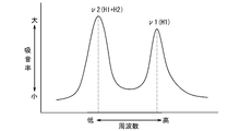
- FIG. 6 is a schematic graph showing sound absorption characteristics of the first acoustic device shown in FIGS. 3 to 5.
- FIG. FIG. 6 is a cross-sectional view corresponding to FIG.
- FIG. 5 is a longitudinal sectional view corresponding to FIG. 4, schematically showing a first acoustic device according to another embodiment of the present invention.
- FIG. 5 is a longitudinal sectional view corresponding to FIG. 4, schematically showing a first acoustic device according to another embodiment of the present invention.
- FIG. 10 is a schematic graph showing sound absorption characteristics of the first acoustic device shown in FIGS. 7 to 9.
- FIG. 5 is a longitudinal sectional view corresponding to FIG. 4 schematically showing a second acoustic device according to another embodiment of the present invention together with the first acoustic device.
- FIG. 12 is a schematic graph showing sound absorption characteristics of the first acoustic device and the second acoustic device shown in FIG. 11.
- FIG. 6 is a cross-sectional view corresponding to FIG. 5, schematically showing a first acoustic device according to another embodiment of the present invention.
- FIG. 6 is a cross-sectional view corresponding to FIG. 5, schematically showing a first acoustic device according to another embodiment of the present invention. It is a figure for demonstrating the example of the shape and arrangement
- an expression indicating that things such as “identical”, “equal”, and “homogeneous” are in an equal state not only represents an exactly equal state, but also has a tolerance or a difference that can provide the same function. It also represents the existing state.
- expressions representing shapes such as quadrangular shapes and cylindrical shapes represent not only geometrically strict shapes such as quadrangular shapes and cylindrical shapes, but also irregularities and chamfers as long as the same effects can be obtained. A shape including a part or the like is also expressed.
- the expressions “comprising”, “comprising”, “comprising”, “including”, or “having” one constituent element are not exclusive expressions for excluding the existence of the other constituent elements.
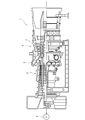
- FIG. 1 is a diagram schematically showing a configuration of a gas turbine 1 according to an embodiment of the present invention.
- a gas turbine 1 according to this embodiment includes a compressor (compression unit) 2, a combustor (combustion unit) 3, and a turbine (turbine unit) 4, for example, a generator 6. Etc. to drive external devices.
- the compressor 2 sucks and compresses atmospheric air, which is external air, and supplies the compressed air to one or more combustors 3.
- the combustor 3 generates high-temperature gas (combustion gas) by burning the fuel supplied from the outside using the air compressed by the compressor 2.
- the turbine 4 receives the supply of the high-temperature gas generated by the combustor 3 to generate a rotational driving force, and outputs the generated rotational driving force to the compressor 2 and an external device.
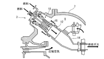
- FIG. 2 is a view for explaining the configuration around the combustor 3 of the gas turbine 1.
- a combustor installation space 8 is provided in the housing 7 of the gas turbine 1, and the combustor installation space 8 is located between the outlet of the compressor 2 and the inlet of the turbine 4. ing.
- the combustor 3 is disposed in the combustor installation space 8, and compressed air flows into the combustor 3 from one end side of the combustor 3.
- fuel is supplied to the combustor 3 from the outside.
- the combustor 3 has a nozzle portion 10, a combustion cylinder 12, and a tail cylinder 14.
- the nozzle unit 10 includes one or more nozzles 16 that inject fuel supplied from the outside into the combustion cylinder 12.
- the nozzle 16 includes, for example, one pilot nozzle 16a and a plurality of main nozzles 16b arranged concentrically around the pilot nozzle 16a.
- the combustion cylinder 12 has a cylindrical shape, for example, a cylindrical shape.
- the nozzle portion 10 is coupled to one end side (upstream end side) of the combustion cylinder 12, and an internal space (combustion space) 18 in which the fuel injected from the nozzle 16 burns is defined inside the combustion cylinder 12. Note that compressed air is supplied to the internal space 18 through the gaps between the nozzles 16, the fuel reacts with the compressed air and burns, and combustion gas is generated.
- the tail cylinder 14 has a cylindrical shape and is coupled to the other end side (downstream end side) of the combustion cylinder 12.
- the cross-sectional shape of the tail cylinder 14 gradually changes in the axial direction of the combustor 3, in other words, in the flow direction of the combustion gas, and the tail cylinder 14 connects the combustion cylinder 12 and the inlet of the turbine 4.
- the combustion cylinder 12 and the tail cylinder 14 are each configured by a plate having a plurality of cooling channels therein.
- the gas turbine 1 includes a first acoustic device (first acoustic liner) 20 attached to the combustor 3.
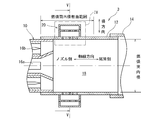
- FIG. 3 is a longitudinal sectional view schematically showing the first acoustic device 20a according to one embodiment of the present invention together with the periphery of the combustion cylinder 12 of the combustor 3.
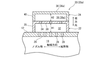
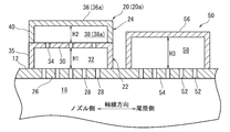
- FIG. 4 is a partial cross-sectional view showing a region IV in FIG. 3 in an enlarged manner.
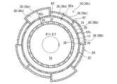
- FIG. 5 is a schematic cross-sectional view taken along line VV in FIG.
- FIG. 6 is a schematic graph showing the sound absorption characteristics of the first acoustic device 20a.
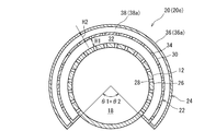
- FIG. 7 is a cross-sectional view corresponding to FIG. 5 schematically showing a first acoustic device 20b according to another embodiment of the present invention.
- 8 and 9 are longitudinal sectional views corresponding to FIG. 4 and schematically showing first acoustic devices 20c and 20d according to another embodiment of the present invention.
- FIG. 10 is a schematic graph showing the sound absorption characteristics of the first acoustic devices 20b, 20c, and 20d.
- FIG. 11 is a longitudinal sectional view corresponding to FIG. 4 schematically showing a second acoustic device 50 according to another embodiment of the present invention together with the first acoustic device 20a.
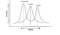
- FIG. 12 is a schematic graph showing the sound absorption characteristics of the first acoustic device 20 a and the second acoustic device 50.
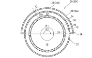
- 13 and 14 are cross-sectional views corresponding to FIG. 5, schematically showing first acoustic devices 20e and 20f according to another embodiment of the present invention.
- the first acoustic device 20 (20 a to 20 f) has a first casing portion 22 and a second casing portion 24.
- the combustion cylinder 12 has a first region 26 covered with the first casing portion 22, and at least one first opening 28 is formed in the first region 26.
- a plurality of first openings 28 are formed in the first region 26, and each first opening 28 has a circular cross-sectional shape.
- the opening area of the first opening 28 is 5% or less of the area of the first region 26.
- the first casing portion 22 has at least one first wall 30 disposed on the outer side of the combustion cylinder 12 so as to face the first region 26. At least one first space 32 is defined between the first region 26 and the first wall 30 that are spaced apart from each other in the radial direction of the combustion cylinder 12 and face each other, and the first space 32 has a first opening 28. It communicates with the internal space 18 through. At least one second opening 34 is formed in the first wall 30.
- the first casing portion 22 has a U-shaped cross-sectional shape in a cross section orthogonal to the circumferential direction of the combustion cylinder 12, and is connected to both sides of the first wall 30 in the axial direction of the combustion cylinder 12. There are two first side walls 35. The first casing portion 22 is fixed to the combustion cylinder 12 by welding, for example.
- the second casing portion 24 has at least one second wall 36 (36a, 36b, 36c) disposed opposite to the first wall 30 outside the first casing portion 22. At least one second space 38 (38a, 38b, 38c) is provided between the first wall 30 and the second wall 36 (36a, 36b, 36c) that are spaced apart from each other in the radial direction of the combustion cylinder 12 and face each other.
- the second space 38 (38a, 38b, 38c) communicates with the first space 32 through the second opening 34.
- At least one second space 38 (38a, 38b, 38c) communicating with the first space 32 through the first opening 28 exists outside the first space 32.
- the first acoustic device 20 (20a to 20f) has a plurality of tuning frequencies ⁇ 1, ⁇ 2 ( ⁇ 2a, ⁇ 2b, ⁇ 2c). For this reason, the first acoustic device 20 can attenuate a plurality of combustion vibration modes having different frequencies.
- the first acoustic devices 20a, 20e, and 20f have one second space 38a.
- the second casing portion 24 has a U-shaped cross-sectional shape in a cross section orthogonal to the circumferential direction of the combustion cylinder 12, and is connected to two second walls 36 on both sides of the second wall 36 in the axial direction of the combustion cylinder 12. Two side walls 40 are provided.
- the second casing part 24 is fixed to the first casing part 22 by welding.
- the first acoustic device 20a has a sound absorption characteristic as shown in FIG. 6, and the first acoustic device 20a has two tuning frequencies ⁇ 1 and ⁇ 2 that increase the sound absorption coefficient, respectively. For this reason, the first acoustic device 20 can attenuate a plurality of combustion vibration modes having different frequencies.
- the low tuning frequency ⁇ 2 of the two tuning frequencies ⁇ 1 and ⁇ 2 in FIG. 6 is the sum of the height H1 of the first space 32 and the height H2 of the second space 38.
- the high-frequency tuning frequency ⁇ 1 is determined by (H1 + H2), and is determined by the height H1 of the first space 32.
- At least one second space 38 includes a plurality of second spaces 38 (38a, 38b, 38c).
- the plurality of second spaces 38 (38a, 38b, 38c) are separated from each other by the partition wall 42, and the heights H2a, H2b, H2c in the radial direction of the combustion cylinder 12 are different.
- the plurality of second spaces 38 (38a, 38b, 38c) separated by the partition walls 42 have different heights H2a, H2b, H2c, so that the first acoustic devices 20b, 20c, 20d are provided.
- the second space 38 has three heights H2a to H2c.
- the set value of the height H2 may be two, or four or more.
- the partition wall 42 may be formed integrally with the second wall 36 (36a, 36b, 36c), or may be joined to the second wall 36 (36a, 36b, 36c) by welding or the like. It may be.
- the second casing portion 24 may be integrally formed or may be composed of a plurality of members. Further, even when the second space 38 has a constant height H2 as shown in FIGS. 3 to 5, FIG. 13 and FIG.
- the second space 38 may be partitioned.
- the plurality of second spaces 38 (38 a, 38 b, 8 c) are arranged along the circumferential direction of the combustion cylinder 12.
- the partition wall 42 extends along the axial direction of the combustion cylinder 12.
- the plurality of second spaces 38 (38a, 38b, 38c) are arranged along the circumferential direction of the combustion cylinder 12, so that the height H2 (H2a, H2b) can be obtained with a simple configuration.
- H2c) can be provided with a plurality of second spaces 38 (38a, 38b, 38c).
- the plurality of second spaces 38 are arranged along the axial direction of the combustion cylinder 12.
- the partition wall 42 extends along the circumferential direction of the combustion cylinder 12.
- the height H2 H2a, H2b
- H2c can be provided with a plurality of second spaces 38 (38a, 38b, 38c).
- the height H2 (H2a, H2b, H2c) of the plurality of second spaces 38 (38a, 38b, 38c) is the nozzle in the axial direction of the combustion cylinder 12. As it gets closer to 16, it becomes lower in steps. In the vicinity of the flame, that is, in the vicinity of the nozzle 16, a combustion vibration mode having a higher frequency tends to occur than in a region far from the flame. Corresponding to this tendency, in the gas turbine 1 configured as described above, the height H2 (H2a, H2b, H2c) of the second space 38 gradually decreases as it approaches the nozzle 16 in the axial direction of the combustion cylinder 12. The high frequency combustion vibration mode near the flame can be damped.
- the first acoustic device 20 (20a to 20f) has a range corresponding to the inner diameter of the combustion cylinder 12 from the tip of the nozzle 16 in the axial direction of the combustion cylinder 12. Is placed inside. Within the range corresponding to the inner diameter of the combustion cylinder 12 from the tip of the nozzle 16, a larger number of combustion vibration modes tend to occur than outside the range. Corresponding to this tendency, in the gas turbine 1 configured as described above, the first acoustic device 20 (20a to 20f) is installed within the range corresponding to the inner diameter of the combustion cylinder 12 in the axial direction of the combustion cylinder 12, A number of combustion vibration modes can be effectively damped.
- the gas turbine 1 further includes a second acoustic device 50 attached to the combustor 3 in addition to the first acoustic device 20 (20a to 20f), as shown in FIG.
- the combustion cylinder 12 further includes a second region 54 in which at least one third opening 52 is formed.
- the second acoustic device 50 has a third wall 56 disposed opposite to the second region 54 on the outside of the combustion cylinder 12, and at least one third wall is provided between the second region 54 and the third wall 56.
- At least one third space 58 communicating with the inside of the combustion cylinder 12 through the opening 52 is defined.
- the second acoustic device 50 has a tuning frequency ⁇ 3 corresponding to the height H3 of the third space 58, as shown in FIG. For this reason, in the gas turbine 1 configured as described above, by providing the second acoustic device 50 in addition to the first acoustic device 20 (20a to 20f), it is possible to attenuate more combustion vibration modes.
- the sum (H1 + H2) of the height H1 of the first space 32 and the height H2 of the second space 38 in the radial direction of the combustion cylinder 12 is the third space. It is higher than the height H3 of 58, and the height H1 of the first space 32 is lower than the height H3 of the third space.
- the tuning frequency ⁇ 3 of the second acoustic device 50 is located between the two frequencies ⁇ 1 and ⁇ 2 of the first acoustic device 20a. For this reason, the combustion vibration mode can be damped continuously over a wide frequency range.
- the sum (H1 + H2) of the height H1 of the first space 32 and the height H2 of the second space 38 of the first acoustic device 20 in the radial direction of the combustion cylinder 12 is the second acoustic device 50. Is equal to the height H3 of the third space 58.
- the tuning frequencies ⁇ 2 and ⁇ 3 are equal, and the sound absorption coefficient near the tuning frequencies ⁇ 2 and ⁇ 3 can be increased.
- the sum (H1 + H2) of the height H1 of the first space 32 and the height H2 of the second space 38 of the first acoustic device 20 in the radial direction of the combustion cylinder 12 is the second acoustic device 50.
- the height H3 of the third space 58 is lower.
- the tuning frequency ⁇ 3 is lower than the tuning frequency ⁇ 2, and the second acoustic device 50 suppresses the combustion vibration mode of a relatively low frequency, while the first acoustic device 20 suppresses the relatively high frequency.
- the combustion vibration mode can be suppressed.
- the first acoustic device 20 (20 a to 20 f) is disposed closer to the nozzle 16 than the second acoustic device 50 in the axial direction of the combustion cylinder 12. ing. The closer to the nozzle 16 there is a tendency for more combustion vibration modes to occur. In response to this tendency, in the gas turbine 1 configured as described above, the first acoustic device 20 is disposed closer to the nozzle 16 than the second acoustic device 50 in the axial direction of the combustion cylinder 12. The combustion vibration mode can be effectively damped.
- the first wall 30 and the second wall 36 do not extend over the entire circumference in the circumferential direction of the combustion cylinder 12, and the combustion cylinder 12 is partially Covered.
- the first wall 30 extends over the entire circumference in the circumferential direction of the combustion cylinder 12, and the second wall partially covers the first wall 30. .
- the central angle ⁇ ⁇ b> 1 representing the existence range of the first wall 30 around the axis of the combustion cylinder 12 is the existence range of the second wall 36.
- the central angle ⁇ 1 representing the existence range of the first wall 30 around the axis of the combustion cylinder 12 is greater than the central angle ⁇ 2 representing the existence range of the second wall 36. ( ⁇ 1> ⁇ 2).
- the second opening 34 formed in the first wall 30 has a circular shape as shown in FIGS. 15 and 16, or alternatively, as shown in FIGS. It has a slit shape or a long hole shape.
- the shape of the 2nd opening 34 formed in the 1st wall 30 is not limited to these, An elliptical shape etc. may be sufficient and you may combine a some shape.
- the ratio of the total area of the second openings 34 to the area of the first wall 30 is set to 5% or less.
- the diameter or width of the second opening 34 is set to be smaller than the height H ⁇ b> 2 of the second space 38.
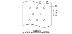
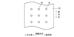
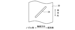
- FIGS. 15 to 19 are diagrams for explaining examples of the shape and arrangement of the second openings 34 applicable to the first acoustic device 20 (20a to 20f). 15 to 19 schematically show a part of the first wall 30 developed on a plane.
- the second openings 34 are arranged in a zigzag pattern (zigzag), or in a grid pattern (lattice pattern) as shown in FIG.
- the second opening 34 extends in the circumferential direction of the combustion cylinder 12 and extends in the circumferential direction of the combustion cylinder 12 as shown in FIG.
- the combustion cylinder 12 extends obliquely with respect to the circumferential direction and the axial direction.
- the arrangement of the second openings 34 formed in the first wall 30 is not limited to the examples shown in FIGS.
- the first casing portion 22 or the second casing portion 24 is formed with a purge hole that opens to the outer surface of the first acoustic device 20 in order to cool the first space 32 or the second space 38. May be.
- the purge space communicates the first space 32 or the second space 38 with the outside of the first acoustic device 20, and the compressed air flowing around the first acoustic device 20 is the first during the operation of the gas turbine 1. It flows into the space 32 or the second space 38.
- the pressure around the first acoustic device 20 is higher than the pressure in the combustion cylinder 12, so that the combustion gas does not flow out from the internal space 18 through the first opening 28.
- the height H1 of the first space 32 is constant in the axial direction and the circumferential direction of the combustion cylinder 12, and the height H2 (H2a, H2b, H2c) of each second space 38 is the combustion cylinder.
- the first wall 30 and the second wall 36 extend along the axial direction and the circumferential direction of the combustion cylinder 12 so as to be constant in the 12 axial directions and the circumferential direction.
- the second space 38 has a quadrangular shape in a cross section orthogonal to the circumferential direction of the combustion cylinder 12, and has a ring shape or a sector shape in a cross section orthogonal to the axial direction of the combustion cylinder 12. .
- the first opening 28 and the second opening 34 are at the same or different positions in the axial direction of the combustion cylinder 12.
- the present invention is not limited to the above-described embodiments, and includes forms obtained by changing the above-described embodiments and forms obtained by combining these forms.
Landscapes
- Engineering & Computer Science (AREA)
- Chemical & Material Sciences (AREA)
- Combustion & Propulsion (AREA)
- Mechanical Engineering (AREA)
- General Engineering & Computer Science (AREA)
- Physics & Mathematics (AREA)
- Acoustics & Sound (AREA)
- Multimedia (AREA)
- Soundproofing, Sound Blocking, And Sound Damping (AREA)
Abstract
Description
例えば特許文献1が開示する音響ライナは、燃焼器の尾筒の内部と通気孔を介して連通するガス空間を規定しており、所定周波数の燃焼振動を減衰可能である。
しかしながら、燃焼振動においては、燃焼状態等の様々な要因により、周波数が大きく異なる複数のモード(燃焼振動モード)が生じる可能性がある。ガスタービンの運転にあたっては、より多くの燃焼振動モードを減衰可能であることが好ましいが、チューニング周波数と周波数が大きく異なる燃焼振動モードの場合、1つの音響ライナでは減衰させることができない。
上記事情に鑑みて、本発明の少なくとも一実施形態の目的は、複数の燃焼振動モードを減衰可能な音響装置を備える燃焼器及びガスタービンを提供することにある。
少なくとも1つの第1開口が形成された第1領域を有する燃焼筒と、
前記燃焼筒内に燃料を噴射するように構成されたノズルと、
前記燃焼筒に取り付けられる第1音響装置と、
を備え、
前記第1音響装置は、
前記燃焼筒の外側に前記第1領域と対向して配置されるとともに少なくとも1つの第2開口が形成された少なくとも1つの第1壁を有し、前記第1領域と前記少なくとも1つの第1壁との間に前記少なくとも1つの第1開口を通じて前記燃焼筒の内部と連通する少なくとも1つの第1空間を区画する第1ケーシング部と、
前記第1ケーシング部の外側に前記少なくとも1つの第1壁と対向して配置される少なくとも1つの第2壁を有し、前記少なくとも1つの第1壁と前記少なくとも1つの第2壁との間に前記少なくとも1つの第2開口を通じて前記少なくとも1つの第1空間と連通する少なくとも1つの第2空間を区画する第2ケーシング部と、
を含む。
前記少なくとも1つの第1開口と前記少なくとも1つの第2開口は、前記燃焼筒の軸線方向で同一又は相違している位置にある。
前記少なくとも1つの第2空間は、隔壁によって相互に分離され且つ前記燃焼筒の径方向での高さが相違する複数の第2空間を含む。
上記構成(3)の燃焼器では、隔壁によって分離された複数の第2空間が異なる高さを有することで、第1音響装置が、より多くのチューニング周波数を有することができる。このため、第1音響装置によって、より多くの燃焼振動モードを減衰させることができる。
前記複数の第2空間は、前記燃焼筒の周方向に沿って配列されている。
上記構成(4)の燃焼器では、複数の第2空間が燃焼筒の周方向に沿って配列されているので、簡単な構成にて、高さの異なる複数の第2空間を設けることができる。
前記複数の第2空間は、前記燃焼筒の軸線方向に沿って配列されている。
上記構成(5)の燃焼器では、複数の第2空間が燃焼筒の軸線方向に沿って配列されているので、簡単な構成にて、高さの異なる複数の第2空間を設けることができる。
前記複数の第2空間の高さは、前記燃焼筒の軸線方向にて前記ノズルに近づくに従って段階的に低くなっている。
火炎近傍すなわちノズル近傍では、火炎から遠い領域に比べ、周波数の高い燃焼振動モードが発生する傾向がある。この傾向に対応して、上記構成(6)の燃焼器では、第2空間の高さが、燃焼筒の軸線方向にてノズルに近づくに従って段階的に低くなっており、火炎近傍の高周波数の燃焼振動モードを減衰させることができる。
前記第1音響装置は、前記燃焼筒の軸線方向にて、前記ノズルの先端から前記燃焼筒の内径相当分の範囲内に配置されている。
ノズル先端から燃焼筒の内径相当分の範囲内では、範囲外に比べ、多数の燃焼振動モードが発生する傾向がある。この傾向に対応して、上記構成(7)の燃焼器では、燃焼筒の軸線方向において、第1音響装置を燃焼筒の内径相当分の範囲内に設置することで、多数の燃焼振動モードを効果的に減衰させることができる。
前記燃焼器に取り付けられる第2音響装置を更に備え、
前記燃焼筒は、少なくとも1つの第3開口が形成された第2領域を更に含み、
前記第2音響装置は、前記燃焼筒の外側に前記第2領域と対向して配置される第3壁を有し、前記第2領域と前記第3壁との間に前記少なくとも1つの第3開口を通じて前記燃焼筒の内部と連通する少なくとも1つの第3空間を区画している。
上記構成(8)の燃焼器では、第1音響装置に加えて第2音響装置を設けることによって、更に多くの燃焼振動モードを減衰させることができる。
前記燃焼筒の径方向での前記第1空間の高さと前記第2空間の高さの合計は、前記第3空間の高さよりも高く、前記第1空間の高さは前記第3空間の高さよりも低い。
上記構成(9)の燃焼器では、第1音響装置が、第1空間の高さに対応したチューニング周波数と、第1空間の高さと第2空間の高さの合計に対応したチューニング周波数とを有する。そして、第2音響装置が、第3空間の高さに対応したチューニング周波数を有し、第2音響装置のチューニング周波数は、第1音響装置の2つの周波数の間に位置する。このため、広い周波数範囲に渡って連続的に燃焼振動モードを減衰させることができる。
前記燃焼筒の軸線方向にて、前記第1音響装置は、前記第2音響装置よりも前記ノズルの近くに配置されている。
ノズルに近いほど、多数の燃焼振動モードが発生する傾向がある。この傾向に対応して、上記構成(10)の燃焼器では、燃焼筒の軸線方向において、第1音響装置を第2音響装置よりもノズルの近くに配置に設置することで、多数の燃焼振動モードを効果的に減衰させることができる。
(11)本発明の少なくとも一実施形態に係るガスタービンは、
上記構成(1)乃至(10)の何れか1つに記載の燃焼器と、
前記燃焼器が前記燃料を燃焼させて発生させた燃焼ガスから回転力を発生させるように構成されたタービンと、
を備える。
上記構成(11)のガスタービンでは、第1音響装置が、第1空間の外側に、第1開口を通じて第1空間と連通する第2空間が存在することにより、複数のチューニング周波数を有する。このため、第1音響装置によって、周波数の異なる複数の燃焼振動モードを減衰させることができる。
例えば、「ある方向に」、「ある方向に沿って」、「平行」、「直交」、「中心」、「同心」或いは「同軸」等の相対的或いは絶対的な配置を表す表現は、厳密にそのような配置を表すのみならず、公差、若しくは、同じ機能が得られる程度の角度や距離をもって相対的に変位している状態も表すものとする。
例えば、「同一」、「等しい」及び「均質」等の物事が等しい状態であることを表す表現は、厳密に等しい状態を表すのみならず、公差、若しくは、同じ機能が得られる程度の差が存在している状態も表すものとする。
例えば、四角形状や円筒形状等の形状を表す表現は、幾何学的に厳密な意味での四角形状や円筒形状等の形状を表すのみならず、同じ効果が得られる範囲で、凹凸部や面取り部等を含む形状も表すものとする。
一方、一の構成要素を「備える」、「具える」、「具備する」、「含む」、又は、「有する」という表現は、他の構成要素の存在を除外する排他的な表現ではない。
圧縮機2は、外部の空気である大気を吸入して圧縮し、圧縮された空気を1つ以上の燃焼器3に供給するものである。
タービン4は、燃焼器3により生成された高温ガスの供給を受けて回転駆動力を発生させ、発生した回転駆動力を圧縮機2及び外部機器に出力するものである。
そして、ガスタービン1は、燃焼器3に取り付けられた第1音響装置(第1音響ライナ)20を有する。
図7は、本発明の他の実施形態に係る第1音響装置20bを概略的に示す、図5に相当する横断面図である。図8及び図9は、本発明の他の実施形態に係る第1音響装置20c,20dを概略的に示す、図4に相当する縦断面図である。図10は、第1音響装置20b,20c,20dの吸音特性を示す概略的なグラフである。
図13及び図14は、本発明の他の実施形態に係る第1音響装置20e,20fを概略的に示す、図5に相当する横断面図である。
なお、第1音響装置20aにおいては、図6の2つのチューニング周波数ν1,ν2のうち、低周波数のチューニング周波数ν2は、第1空間32の高さH1と第2空間38の高さH2の合計(H1+H2)によって決定され、高周波数のチューニング周波数ν1は、第1空間32の高さH1によって決定される。
幾つかの実施形態では、第1空間32高さH1は第2空間38の高さH2よりも大きい(H1>H2)。
幾つかの実施形態では、第1空間32の高さH1は第2空間38の高さH2よりも小さい(H1<H2)。
上記構成のガスタービン1では、隔壁42によって分離された複数の第2空間38(38a,38b,38c)が異なる高さH2a,H2b,H2cを有することで、第1音響装置20b,20c,20dが、より多くのチューニング周波数ν1,ν2(ν2a,ν2b,ν2c)を有することができる。このため、第1音響装置20b,20c,20dによって、より多くの燃焼振動モードを減衰させることができる。
また、隔壁42は、第2壁36(36a,36b,36c)と一体に成形されたものであってもよいし、第2壁36(36a,36b,36c)に溶接等により結合されたものであってもよい。換言すれば、第2ケーシング部24は、一体に成形されたものであってもよいし、複数の部材からなるものであってもよい。
更に、図3~5、図13及び図14に示したように第2空間38が一定の高さH2を有している場合でも、第2ケーシング部24の内部に隔壁42を設けて複数の第2空間38を区画してもよい。
上記構成のガスタービン1では、複数の第2空間38(38a,38b,38c)が燃焼筒12の周方向に沿って配列されているので、簡単な構成にて、高さH2(H2a,H2b,H2c)の異なる複数の第2空間38(38a,38b,38c)を設けることができる。
上記構成のガスタービン1では、複数の第2空間38(38a,38b,38c)が燃焼筒12の軸線方向に沿って配列されているので、簡単な構成にて、高さH2(H2a,H2b,H2c)の異なる複数の第2空間38(38a,38b,38c)を設けることができる。
火炎近傍すなわちノズル16近傍では、火炎から遠い領域に比べ、周波数の高い燃焼振動モードが発生する傾向がある。この傾向に対応して、上記構成のガスタービン1では、第2空間38の高さH2(H2a,H2b,H2c)が、燃焼筒12の軸線方向にてノズル16に近づくに従って段階的に低くなっており、火炎近傍の高周波数の燃焼振動モードを減衰させることができる。
ノズル16先端から燃焼筒12の内径相当分の範囲内では、範囲外に比べ、多数の燃焼振動モードが発生する傾向がある。この傾向に対応して、上記構成のガスタービン1では、燃焼筒12の軸線方向において、第1音響装置20(20a~20f)を燃焼筒12の内径相当分の範囲内に設置することで、多数の燃焼振動モードを効果的に減衰させることができる。
この場合、燃焼筒12は、少なくとも1つの第3開口52が形成された第2領域54を更に含む。第2音響装置50は、燃焼筒12の外側に第2領域54と対向して配置される第3壁56を有し、第2領域54と第3壁56との間に少なくとも1つの第3開口52を通じて燃焼筒12の内部と連通する少なくとも1つの第3空間58を区画する。
第2音響装置50は、図12に示したように、第3空間58の高さH3に応じたチューニング周波数ν3を有する。このため、上記構成のガスタービン1では、第1音響装置20(20a~20f)に加えて第2音響装置50を設けることによって、更に多くの燃焼振動モードを減衰させることができる。
上記構成のガスタービン1では、第2音響装置50のチューニング周波数ν3は、第1音響装置20aの2つの周波数ν1,ν2の間に位置する。このため、広い周波数範囲に渡って連続的に燃焼振動モードを減衰させることができる。
ノズル16に近いほど、多数の燃焼振動モードが発生する傾向がある。この傾向に対応して、上記構成のガスタービン1では、燃焼筒12の軸線方向において、第1音響装置20を第2音響装置50よりもノズル16の近くに配置に設置することで、多数の燃焼振動モードを効果的に減衰させることができる。
幾つかの実施形態では、図14に示したように、第1壁30は燃焼筒12の周方向にて全周に渡って延び、第2壁は第1壁30を部分的に覆っている。
幾つかの実施形態では、図5、図7及び図13に示したように、燃焼筒12の軸線周りでの第1壁30の存在範囲を表す中心角θ1は、第2壁36の存在範囲を表す中心角θ2と一致している(θ1=θ2)。
幾つかの実施形態では、図14に示したように、燃焼筒12の軸線周りでの第1壁30の存在範囲を表す中心角θ1は、第2壁36の存在範囲を表す中心角θ2よりも大きい(θ1>θ2)。
幾つかの実施形態では、第2開口34の直径又は幅は、第2空間38の高さH2よりも小さく設定される。
幾つかの実施形態では、図15に示したように、第2開口34は、千鳥状(ジグザグ)に配列され、あるいは、図16に示したようにグリッド状(格子状)に配列される。
幾つかの実施形態では、図17に示したように、第2開口34は、燃焼筒12の周方向に延び、図18に示したように、燃焼筒12の周方向に延び、或いは、図19に示したように、燃焼筒12の周方向及び軸線方向に対し斜めに延びている。
なお、第1壁30に形成される第2開口34の配置は、図15~図19に示した例に限定されることはない。
幾つかの実施形態では、第2空間38は、燃焼筒12の周方向と直交する断面にて四角形状を有し、燃焼筒12の軸線方向と直交する断面にて環形状又はセクタ形状を有する。
幾つかの実施形態では、第1開口28と第2開口34は、燃焼筒12の軸線方向で同一又は相違している位置にある。
2 圧縮機
3 燃焼器
4 タービン
6 発電機(外部機器)
7 ハウジング
8 燃焼器設置スペース
10 ノズル部
12 燃焼筒
14 尾筒
16 ノズル
16a パイロットノズル
16b メインノズル
18 内部空間
20(20a~20f) 第1音響装置
22 第1ケーシング部
24 第2ケーシング部
26 第1領域
28 第1開口
30 第1壁
32 第1空間
34 第2開口
35 第1側壁
36(38a~38c) 第2壁
38(38a~38c) 第2空間
40 第2側壁
42 隔壁
50 第2音響装置
52 第3開口
54 第2領域
56 第3壁
58 第3空間
Claims (11)
- 少なくとも1つの第1開口が形成された第1領域を有する燃焼筒と、
前記燃焼筒内に燃料を噴射するように構成されたノズルと、
前記燃焼筒に取り付けられる第1音響装置と、
を備え、
第1音響装置は、
前記燃焼筒の外側に前記第1領域と対向して配置されるとともに少なくとも1つの第2開口が形成された少なくとも1つの第1壁を有し、前記第1領域と前記少なくとも1つの第1壁との間に前記少なくとも1つの第1開口を通じて前記燃焼筒の内部と連通する少なくとも1つの第1空間を区画する第1ケーシング部と、
前記第1ケーシング部の外側に前記少なくとも1つの第1壁と対向して配置される少なくとも1つの第2壁を有し、前記少なくとも1つの第1壁と前記少なくとも1つの第2壁との間に前記少なくとも1つの第2開口を通じて前記少なくとも1つの第1空間と連通する少なくとも1つの第2空間を区画する第2ケーシング部と、
を含む、
ことを特徴とする燃焼器。 - 前記少なくとも1つの第1開口と前記少なくとも1つの第2開口は、前記燃焼筒の軸線方向で同一又は相違している位置にあることを特徴とする請求項1に記載の燃焼器。
- 前記少なくとも1つの第2空間は、隔壁によって相互に分離され且つ前記燃焼筒の径方向での高さが相違する複数の第2空間を含む
ことを特徴とする請求項1又は2に記載の燃焼器。 - 前記複数の第2空間は、前記燃焼筒の周方向に沿って配列されている
ことを特徴とする請求項3に記載の燃焼器。 - 前記複数の第2空間は、前記燃焼筒の軸線方向に沿って配列されている
ことを特徴とする請求項3又は4に記載の燃焼器。 - 前記複数の第2空間の高さは、前記燃焼筒の軸線方向にて前記ノズルに近づくに従って段階的に低くなっている
ことを特徴とする請求項5に記載の燃焼器。 - 前記第1音響装置は、前記燃焼筒の軸線方向にて、前記ノズルの先端から前記燃焼筒の内径相当分の範囲内に配置されている
ことを特徴とする請求項1乃至6の何れか1項に記載の燃焼器。 - 前記燃焼器に取り付けられる第2音響装置を更に備え、
前記燃焼筒は、少なくとも1つの第3開口が形成された第2領域を更に含み、
前記第2音響装置は、前記燃焼筒の外側に前記第2領域と対向して配置される第3壁を有し、前記第2領域と前記第3壁との間に前記少なくとも1つの第3開口を通じて前記燃焼筒の内部と連通する少なくとも1つの第3空間を区画している
ことを特徴とする請求項1乃至7の何れか1項に記載の燃焼器。 - 前記燃焼筒の径方向での前記第1空間の高さと前記第2空間の高さの合計は、前記第3空間の高さよりも高く、前記第1空間の高さは前記第3空間の高さよりも低い
ことを特徴とする請求項8に記載の燃焼器。 - 前記燃焼筒の軸線方向にて、前記第1音響装置は、前記第2音響装置よりも前記ノズルの近くに配置されている
ことを特徴とする請求項8又は9に記載の燃焼器。 - 請求項1乃至請求項10の何れか1項に記載の燃焼器と、
前記燃焼器が前記燃料を燃焼させて発生させた燃焼ガスから回転力を発生させるように構成されたタービンと、
を備えることを特徴とするガスタービン。
Priority Applications (4)
| Application Number | Priority Date | Filing Date | Title |
|---|---|---|---|
| DE112016002108.9T DE112016002108B4 (de) | 2015-07-08 | 2016-07-06 | Brennkammer und Gasturbine |
| US15/736,064 US10712004B2 (en) | 2015-07-08 | 2016-07-06 | Combustor including an acoustic device mounted on a combustion liner for damping combustion oscillation of a predetermined frequency and gas turbine |
| KR1020177036177A KR102055493B1 (ko) | 2015-07-08 | 2016-07-06 | 연소기 및 가스 터빈 |
| CN201680015810.1A CN107407484B (zh) | 2015-07-08 | 2016-07-06 | 燃烧器以及燃气涡轮 |
Applications Claiming Priority (2)
| Application Number | Priority Date | Filing Date | Title |
|---|---|---|---|
| JP2015137077A JP6579834B2 (ja) | 2015-07-08 | 2015-07-08 | 燃焼器及びガスタービン |
| JP2015-137077 | 2015-07-08 |
Publications (1)
| Publication Number | Publication Date |
|---|---|
| WO2017006971A1 true WO2017006971A1 (ja) | 2017-01-12 |
Family
ID=57685119
Family Applications (1)
| Application Number | Title | Priority Date | Filing Date |
|---|---|---|---|
| PCT/JP2016/070051 Ceased WO2017006971A1 (ja) | 2015-07-08 | 2016-07-06 | 燃焼器及びガスタービン |
Country Status (6)
| Country | Link |
|---|---|
| US (1) | US10712004B2 (ja) |
| JP (1) | JP6579834B2 (ja) |
| KR (1) | KR102055493B1 (ja) |
| CN (1) | CN107407484B (ja) |
| DE (1) | DE112016002108B4 (ja) |
| WO (1) | WO2017006971A1 (ja) |
Cited By (2)
| Publication number | Priority date | Publication date | Assignee | Title |
|---|---|---|---|---|
| JP2020515798A (ja) * | 2017-03-30 | 2020-05-28 | シーメンス アクティエンゲゼルシャフト | ガスタービンエンジンの燃焼器セクションにおける冷却流体の二重利用のための導管配置を備えたシステム |
| JPWO2021132128A1 (ja) * | 2019-12-24 | 2021-07-01 |
Families Citing this family (11)
| Publication number | Priority date | Publication date | Assignee | Title |
|---|---|---|---|---|
| US10670271B2 (en) * | 2016-09-30 | 2020-06-02 | DOOSAN Heavy Industries Construction Co., LTD | Acoustic dampening liner cap and gas turbine combustor including the same |
| US11536174B2 (en) * | 2017-07-20 | 2022-12-27 | President And Fellows Of Harvard College | Acoustic damper for gas turbine combustors with orthogonal slots |
| JP7289752B2 (ja) * | 2019-08-01 | 2023-06-12 | 三菱重工業株式会社 | 音響減衰器、筒アッセンブリ、燃焼器、ガスタービン及び筒アッセンブリの製造方法 |
| JP7262364B2 (ja) * | 2019-10-17 | 2023-04-21 | 三菱重工業株式会社 | ガスタービン燃焼器 |
| JP7393262B2 (ja) * | 2020-03-23 | 2023-12-06 | 三菱重工業株式会社 | 燃焼器、及びこれを備えるガスタービン |
| JP6980144B1 (ja) * | 2021-03-24 | 2021-12-15 | 三菱パワー株式会社 | ガスタービン用燃焼器、ガスタービン及びガスタービンの組立方法 |
| JP7867366B2 (ja) * | 2022-04-18 | 2026-05-29 | 三菱重工業株式会社 | 燃焼器、及びこれを備えるガスタービン |
| US12535212B2 (en) * | 2022-06-29 | 2026-01-27 | General Electric Company | Acoustic liner for a gas turbine engine |
| CN120418590A (zh) * | 2023-02-22 | 2025-08-01 | 三菱重工业株式会社 | 燃烧器用筒体、燃烧器及燃气轮机 |
| GB2632877A (en) * | 2023-08-14 | 2025-02-26 | Siemens Energy Global Gmbh & Co Kg | Combustor with resonator for gas turbine engine |
| CN119042669B (zh) * | 2024-07-29 | 2025-12-26 | 北京航空航天大学 | 燃烧室及燃烧室中吸声结构的参数确定方法、装置和设备 |
Citations (4)
| Publication number | Priority date | Publication date | Assignee | Title |
|---|---|---|---|---|
| US20050034918A1 (en) * | 2003-08-15 | 2005-02-17 | Siemens Westinghouse Power Corporation | High frequency dynamics resonator assembly |
| JP2013117231A (ja) * | 2009-02-27 | 2013-06-13 | Mitsubishi Heavy Ind Ltd | 燃焼器およびこれを備えたガスタービン |
| US20150020498A1 (en) * | 2013-07-19 | 2015-01-22 | Reinhard Schilp | Cooling cover for gas turbine damping resonator |
| JP2015518534A (ja) * | 2012-03-21 | 2015-07-02 | アルストム テクノロジー リミテッドALSTOM Technology Ltd | 燃焼室内の複数の位置での同時かつ広帯域の減衰 |
Family Cites Families (8)
| Publication number | Priority date | Publication date | Assignee | Title |
|---|---|---|---|---|
| DE10243884A1 (de) | 2002-09-21 | 2004-04-01 | Mann + Hummel Gmbh | Resonatorschalldämpfer |
| JP2008121961A (ja) | 2006-11-10 | 2008-05-29 | Mitsubishi Heavy Ind Ltd | ガスタービン燃焼器用の音響ライナー |
| JP4981615B2 (ja) | 2007-10-19 | 2012-07-25 | 三菱重工業株式会社 | ガスタービン |
| US8789372B2 (en) * | 2009-07-08 | 2014-07-29 | General Electric Company | Injector with integrated resonator |
| US8413443B2 (en) * | 2009-12-15 | 2013-04-09 | Siemens Energy, Inc. | Flow control through a resonator system of gas turbine combustor |
| EP2385303A1 (en) * | 2010-05-03 | 2011-11-09 | Alstom Technology Ltd | Combustion Device for a Gas Turbine |
| WO2012127959A1 (ja) * | 2011-03-22 | 2012-09-27 | 三菱重工業株式会社 | 音響ダンパ、燃焼器およびガスタービン |
| US9163837B2 (en) * | 2013-02-27 | 2015-10-20 | Siemens Aktiengesellschaft | Flow conditioner in a combustor of a gas turbine engine |
-
2015
- 2015-07-08 JP JP2015137077A patent/JP6579834B2/ja active Active
-
2016
- 2016-07-06 KR KR1020177036177A patent/KR102055493B1/ko active Active
- 2016-07-06 CN CN201680015810.1A patent/CN107407484B/zh active Active
- 2016-07-06 WO PCT/JP2016/070051 patent/WO2017006971A1/ja not_active Ceased
- 2016-07-06 US US15/736,064 patent/US10712004B2/en active Active
- 2016-07-06 DE DE112016002108.9T patent/DE112016002108B4/de active Active
Patent Citations (4)
| Publication number | Priority date | Publication date | Assignee | Title |
|---|---|---|---|---|
| US20050034918A1 (en) * | 2003-08-15 | 2005-02-17 | Siemens Westinghouse Power Corporation | High frequency dynamics resonator assembly |
| JP2013117231A (ja) * | 2009-02-27 | 2013-06-13 | Mitsubishi Heavy Ind Ltd | 燃焼器およびこれを備えたガスタービン |
| JP2015518534A (ja) * | 2012-03-21 | 2015-07-02 | アルストム テクノロジー リミテッドALSTOM Technology Ltd | 燃焼室内の複数の位置での同時かつ広帯域の減衰 |
| US20150020498A1 (en) * | 2013-07-19 | 2015-01-22 | Reinhard Schilp | Cooling cover for gas turbine damping resonator |
Cited By (5)
| Publication number | Priority date | Publication date | Assignee | Title |
|---|---|---|---|---|
| JP2020515798A (ja) * | 2017-03-30 | 2020-05-28 | シーメンス アクティエンゲゼルシャフト | ガスタービンエンジンの燃焼器セクションにおける冷却流体の二重利用のための導管配置を備えたシステム |
| JP7008722B2 (ja) | 2017-03-30 | 2022-01-25 | シーメンス アクティエンゲゼルシャフト | ガスタービンエンジンの燃焼器セクションにおける冷却流体の二重利用のための導管配置を備えたシステム |
| JPWO2021132128A1 (ja) * | 2019-12-24 | 2021-07-01 | ||
| WO2021132128A1 (ja) * | 2019-12-24 | 2021-07-01 | 三菱パワー株式会社 | 燃焼器部品、この燃焼器部品を備える燃焼器、及びこの燃焼器を備えるガスタービン |
| JP7284293B2 (ja) | 2019-12-24 | 2023-05-30 | 三菱重工業株式会社 | 燃焼器部品、この燃焼器部品を備える燃焼器、及びこの燃焼器を備えるガスタービン |
Also Published As
| Publication number | Publication date |
|---|---|
| DE112016002108B4 (de) | 2021-02-04 |
| US10712004B2 (en) | 2020-07-14 |
| JP6579834B2 (ja) | 2019-09-25 |
| KR102055493B1 (ko) | 2019-12-12 |
| CN107407484A (zh) | 2017-11-28 |
| DE112016002108T5 (de) | 2018-03-08 |
| US20180180288A1 (en) | 2018-06-28 |
| KR20180008687A (ko) | 2018-01-24 |
| CN107407484B (zh) | 2019-12-03 |
| JP2017020682A (ja) | 2017-01-26 |
Similar Documents
| Publication | Publication Date | Title |
|---|---|---|
| JP6579834B2 (ja) | 燃焼器及びガスタービン | |
| JP5995932B2 (ja) | 燃焼器およびガスタービン | |
| JP6059902B2 (ja) | ガスタービンエンジンに用いられる音響減衰装置 | |
| JP5291790B2 (ja) | 燃焼器およびこれを備えたガスタービン | |
| JP5112926B2 (ja) | 燃焼器ダイナミクスを低減するためのシステム | |
| EP3034945B1 (en) | Gas turbine fuel pipe comprising a damper | |
| US20150096829A1 (en) | Acoustic damping device | |
| US11536455B2 (en) | Combustor component, combustor, gas turbine, and manufacturing method for combustor component | |
| US10197275B2 (en) | High frequency acoustic damper for combustor liners | |
| JP2013140248A (ja) | 音響装置及びガスタービン燃焼器 | |
| JP6125651B2 (ja) | ガスタービンエンジンの燃焼器のための音響減衰システム | |
| JP6797728B2 (ja) | ガスタービン燃焼器の共鳴吸音装置並びにこれを備えたガスタービン燃焼器及びガスタービン | |
| JP6444383B2 (ja) | ガスタービンエンジンの燃焼器用の音響減衰システム | |
| JP5054988B2 (ja) | 燃焼器 | |
| CN114402167A (zh) | 用于燃烧室前板中有多个体积的声学阻尼器的系统和方法 | |
| US20150101332A1 (en) | Combustion chamber of a gas turbine with improved acoustic damping | |
| JP6100295B2 (ja) | 燃料ノズル、これを備えた燃焼器及びガスタービン | |
| JP5762481B2 (ja) | 燃料ノズル、これを備えた燃焼器及びガスタービン | |
| KR20250034514A (ko) | 가스 터빈용 냉각 유체 가이드 및 가스 터빈 | |
| JP5717821B2 (ja) | ガスタービン燃焼器用の音響ライナー、ガスタービン燃焼器、およびガスタービン | |
| JP2008304125A (ja) | 音響ダンパの振動低減構造 | |
| JP2010286141A (ja) | 燃料ノズル、これを備えた燃焼器及びガスタービン |
Legal Events
| Date | Code | Title | Description |
|---|---|---|---|
| 121 | Ep: the epo has been informed by wipo that ep was designated in this application |
Ref document number: 16821440 Country of ref document: EP Kind code of ref document: A1 |
|
| WWE | Wipo information: entry into national phase |
Ref document number: 112016002108 Country of ref document: DE |
|
| WWE | Wipo information: entry into national phase |
Ref document number: 15736064 Country of ref document: US |
|
| ENP | Entry into the national phase |
Ref document number: 20177036177 Country of ref document: KR Kind code of ref document: A |
|
| 122 | Ep: pct application non-entry in european phase |
Ref document number: 16821440 Country of ref document: EP Kind code of ref document: A1 |