WO2017006443A1 - 波動歯車装置および波動発生器 - Google Patents
波動歯車装置および波動発生器 Download PDFInfo
- Publication number
- WO2017006443A1 WO2017006443A1 PCT/JP2015/069571 JP2015069571W WO2017006443A1 WO 2017006443 A1 WO2017006443 A1 WO 2017006443A1 JP 2015069571 W JP2015069571 W JP 2015069571W WO 2017006443 A1 WO2017006443 A1 WO 2017006443A1
- Authority
- WO
- WIPO (PCT)
- Prior art keywords
- plug
- wave generator
- gear
- internal
- flange
- Prior art date
- Legal status (The legal status is an assumption and is not a legal conclusion. Google has not performed a legal analysis and makes no representation as to the accuracy of the status listed.)
- Ceased
Links
Images


Classifications
-
- F—MECHANICAL ENGINEERING; LIGHTING; HEATING; WEAPONS; BLASTING
- F16—ENGINEERING ELEMENTS AND UNITS; GENERAL MEASURES FOR PRODUCING AND MAINTAINING EFFECTIVE FUNCTIONING OF MACHINES OR INSTALLATIONS; THERMAL INSULATION IN GENERAL
- F16H—GEARING
- F16H49/00—Other gearings
- F16H49/001—Wave gearings, e.g. harmonic drive transmissions
Definitions
- the present invention relates to a wave generator of a wave gear device called a flat type, and more particularly to a wave generator provided with two wave generator bearings.
- a wave generator of a typical flat wave gear device includes a rigid plug and a wave generator bearing attached to an elliptical outer peripheral surface of the plug.
- the flexible external gear of the flat wave gear device is bent in an elliptical shape by a wave generator and partially meshed with the stationary internal gear and the output internal gear.
- Patent Document 1 discloses a flat wave gear device in which a wave generator having two wave generator bearings is incorporated.
- the stationary internal gear is attached to a fixed member such as a device housing
- the output internal gear is attached to a load member
- the wave generator is attached to a motor shaft or the like. Attached to the rotary input member. Misalignment is likely to occur between three members attached to separate members. When misalignment occurs between the three members, the load applied to the wave gear device increases, and the life and strength of the wave gear device may be reduced.
- an object of the present invention is to provide a wave generator that can reduce the adverse effects caused by misalignment of component parts, and a wave gear device including the wave generator.
- the present invention flexes an external gear into a non-circular shape, partially meshes with each of the first and second internal gears, and the external gear and the first gear.
- the rigid plug is divided into a first plug to which the first bearing is attached and a second plug to which the second bearing is attached.
- the first and second plugs are connected by Oldham coupling. Therefore, the misalignment between the first and second bearings is absorbed or alleviated by the Oldham coupling.
- a flat type wave gear device in which a wave generator is incorporated, between a first internal gear (for example, a stationary-side internal gear) and a second internal gear (for example, an output-side internal gear).
- a first internal gear for example, a stationary-side internal gear
- a second internal gear for example, an output-side internal gear.
- Oldham coupling A hub supporting the first and second plugs with a predetermined play in the radial direction; A flange formed on the hub and positioned between the first and second plugs; A first insert that is slidable in mutually different radial directions with respect to the flange and the first plug, and is connected to be integrally rotatable; An Oldham coupling including a second insert that is slidable in mutually different radial directions and connected to be integrally rotatable with respect to the flange and the second plug can be used.
- Oldham coupling A hub supporting the first and second plugs with a predetermined play in the radial direction; A flange formed on the hub, sandwiching the second plug, and positioned on the opposite side of the first plug; A first insert that is slidable in mutually different radial directions with respect to the first plug and the second plug, and is coupled to be integrally rotatable; You may provide the 2nd insert which can be slid to a mutually different radial direction with respect to the said flange and the said 2nd plug, and is connected so that integral rotation is possible.
- Oldham coupling A hub in which the second plug is supported in a state of a predetermined play in a radial direction, and the first plug is integrally formed;
- the first and second plugs may be provided with disc-shaped inserts that are slidable in a radial direction perpendicular to each other and connected to be integrally rotatable.
- the wave generator of the present invention is A plug, First and second bearings fixed to the non-circular outer peripheral surface of the plug; With Oldham coupling,
- the Oldham coupling is A hub supporting the plug with a predetermined play in the radial direction;
- the flange and the plug are slidable in mutually different radial directions, and include an insert that is connected so as to be integrally rotatable.
- FIG. 2 is a longitudinal sectional view of the wave generator of FIG. 1 and an exploded perspective view of an Oldham coupling. It is a longitudinal cross-sectional view which shows another example of the Oldham coupling of FIG. It is a longitudinal cross-sectional view which shows another example of the Oldham coupling of FIG. It is a longitudinal cross-sectional view which shows another example of the wave generator of FIG.
- FIG. 1 (a) is a longitudinal sectional view showing a flat wave gear device according to the present embodiment
- FIG. 1 (b) is a front view thereof.
- the flat wave gear device 1 includes a stationary-side internal gear 2 and an output-side internal gear 3, a cylindrical flexible external gear 4, and a wave generator 5.
- the internal gears 2 and 3 are coaxially arranged with a slight gap in the direction of the central axis 1a.
- the external gear 4 is arranged coaxially inside the internal gears 2 and 3.
- the external gear 4 has a tooth width including the internal gears 2 and 3.
- the external tooth 4 a of the external gear 4 has a portion on one side in the tooth width direction facing the internal tooth 2 a of the first internal gear 2, and a portion on the other side of the internal gear of the second internal gear 3. Confronts 3a.
- the wave generator 5 bends the external gear 4 into a non-circular shape, in this example an ellipse, and meshes with the internal gears 2 and 3 at the position of the elliptical long axis L.
- the wave generator 5 rotates, the meshing position between the external gear 4 and the internal gears 2 and 3 moves in the circumferential direction.
- the number of teeth of the internal gear 3 on the output side is 2n fewer than the number of teeth of the internal gear 2 on the stationary side (n is a positive integer).
- the number of teeth of the internal gear 3 and the external gear 4 is the same. While the wave generator 5 rotates once, the external gear 4 rotates relative to the stationary internal gear 2 by an angle corresponding to the difference in the number of teeth.
- the internal gear 3 on the output side rotates integrally with the external gear 4. The rotation of the internal gear 3 is output to a load member (not shown).
- the internal gear 2 with a large number of teeth is a stationary internal gear
- the internal gear 3 with a small number of teeth is a stationary internal gear and the other internal gear 2 is output.
- a side internal gear It is also possible to use a side internal gear.
- Various forms can be adopted as the number of teeth of each gear. For example, when realizing a flat wave gear device with a reduced speed ratio, as the external gear 4, the number of teeth of the external tooth portion that meshes with the internal gear 2 and the number of teeth of the external tooth portion that meshes with the internal gear 3. The thing of different structure can be used.
- FIG. 2 (a) is a schematic diagram showing the configuration of the wave generator 5, and FIG. 2 (b) is an exploded perspective view of the Oldham coupling.
- the wave generator 5 includes a first plug 11, a second plug 12, and a first plug fixed to the elliptical outer peripheral surface 11 a of the first plug 11 by press-fitting and an adhesive.
- Oldham coupling 15 has a symmetrical shape in the direction of the central axis.
- the Oldham coupling 15 includes a cylindrical hub 16, and a disc-shaped flange 17 is formed at the center of the circular outer peripheral surface 16 a of the hub 16 in the direction of the central axis 1 a, which extends radially outward.
- the Oldham coupling 15 includes a first insert 18 and a second insert 19.
- the hub portion on one side of the flange 17 in the hub 16 is inserted into the circular central hole 11b of the first plug 11 having a constant thickness with a slight play, and the hub portion on the other side is inserted with a constant thickness.
- the plug 2 is inserted into the circular center hole 12b of the plug 12 with a slight play.
- the disc-shaped first insert 18 is supported between the first plug 11 and the flange 17 on the circular outer peripheral surface 16a of the hub 16 with a slight play in the radial direction.
- the flange 17 is formed with grooves 17a and 17b having a constant width and opened outward in the radial direction formed at an angular interval of 90 degrees.
- a pair of protrusions 18a that are fitted in the pair of grooves 17a and are slidable in the radial direction along the grooves 17a are formed on the end surface of the first insert 18 facing the flange 17.
- a pair of protrusions 18 b formed at positions rotated by 90 degrees with respect to the pair of protrusions 18 a are formed on the opposite end face of the first insert 18.
- the pair of protrusions 18b are fitted into a pair of grooves (not shown) formed on the opposing end surfaces of the first plug 11, and are slidable in the radial direction along the grooves.
- the other disc-shaped second insert 19 has a similar structure, and a pair of protrusions 19b are formed on one end face, and these protrusions 19b are fitted into the pair of grooves 17b of the flange 17 so as to be slidable in the radial direction. is there.
- a pair of protrusions 19 a are formed on the other end surface of the second insert 19, and these protrusions 19 a are fitted into a pair of grooves (not shown) formed on the opposite end surfaces of the second plug 12. It can slide radially along the groove.
- first insert 18 is connected to the flange 17 and the first plug 11 so as to be slidable in radial directions orthogonal to each other and integrally rotatable.
- the second insert 19 is slidable in a radial direction orthogonal to the flange 17 and the second plug 12 and is connected to be integrally rotatable.
- the outer peripheral edge portion 18c of the first insert 18 functions as a retainer press for restraining the movement of the ball retainer 13a of the first bearing 13.
- the outer peripheral edge portion 19 c of the second insert 19 functions as a retainer presser for the ball retainer 14 a of the second bearing 14.
- the first and second plugs 11 and 12 are coupled to the wave generator 5 of the flat wave gear device 1 of this example via an Oldham coupling 15. Therefore, the misalignment between the first and second bearings 13 and 14 is absorbed or alleviated by the Oldham coupling 15. Therefore, due to the misalignment, the load acting on the first and second bearings 13 and 14 increases, and adverse effects such as a decrease in the service life thereof can be avoided or suppressed.
- the hub 16 of the Oldham coupling 15 is connected to a rotation input shaft (not shown) such as a motor shaft, and the stationary internal gear 2 is connected to a device housing (not shown). ) Etc., and the internal gear 3 on the output side is connected to a load side member (not shown). The misalignment between these three members is also absorbed or alleviated by the Oldham coupling 15.
- the flat wave gear device 1 it is possible to avoid or suppress adverse effects such as a decrease in the life and strength of the component due to an increase in the load caused by misalignment between the components.
- first and second inserts 18 and 19 of this example are each slidable in a radial direction perpendicular to the member to be connected.
- the sliding direction is not limited to the orthogonal radial direction. It only needs to be slidable in two different radial directions. Also in each example of Oldham coupling described later, the case where the sliding direction of the insert is a radial direction orthogonal to each other will be described, but it may be two different radial directions.
- the flange 17, the first and second plugs 11 and 12 are provided with grooves, and the first and second inserts 18 and 19 are provided with protrusions.
- protrusions may be provided on the flange 17, the first and second plugs 11 and 12, and grooves may be provided on the first and second inserts 18 and 19. This is the same in the following examples.
- FIG. 3 is a schematic diagram showing another configuration example of the Oldham coupling 15.
- An Oldham coupling 15A assembled to the wave generator 5A shown in this figure includes a cylindrical hub 16A that supports the first and second plugs 11 and 12 with a predetermined play in the radial direction.
- a disc-shaped flange 17 ⁇ / b> A is integrally formed on the hub 16 ⁇ / b> A at the end opposite to the first plug 11.
- the first insert 18A is disposed between the first plug 11 and the second plug 12.
- the first insert 18A is slidable in a radial direction perpendicular to the first plug 11 and the second plug 12, and is connected to be integrally rotatable.
- a second insert 19 ⁇ / b> A is disposed between the flange 17 ⁇ / b> A and the second plug 12.
- the second insert 19A is slidable in a radial direction perpendicular to each other and connected to the flange 17A and the second plug 12 so as to be integrally rotatable.
- FIG. 4 is a schematic view showing still another example of the Oldham coupling 15.
- the hub 16B supports the second plug 12 with a predetermined play in the radial direction, and the first plug 11 is integrally formed. Further, it has only one disc-like insert 18B, and the insert 18B is slidable in a radial direction perpendicular to each other and connected to the first and second plugs 11 and 12 so as to be integrally rotatable. Yes.
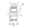
- FIG. 5 is a schematic diagram showing another example of the wave generator 5.
- the wave generator 5C shown in this figure includes a wide single plug 11C, first and second bearings 13 and 14, and an Oldham coupling 15C.
- the outer peripheral surface of the plug 11C is an elliptical outer peripheral surface 11d.
- the first bearing 13 and the second bearing 14 are fixed to the elliptical outer peripheral surface 11d by press-fitting and an adhesive with a predetermined interval in the direction of the central axis 1a.
- An annular retainer retainer 21 is disposed between the first and second bearings 13 and 14 so that the ball retainers 13a and 14a of both bearings 13 and 14 do not come off in the direction of the central axis 1a.
- the Oldham coupling 15C includes a cylindrical hub 16C that is inserted into the circular center hole 11e of the plug 11C in a playable state, and a disk that extends radially outward is provided at one end of the hub 16C.
- a flange 17C is integrally formed.
- One disc-shaped insert 18C is disposed between the flange 17C and the end face of the plug 11C facing the flange 17C.
- the insert 18C is supported by the hub 16C so as to be slightly movable in the radial direction, and is slidable in the radial direction perpendicular to each other and connected to the flange 17C and the plug 11C so as to be integrally rotatable.
- the plug of the wave generator has an elliptical outer peripheral surface, and the external gear is bent in an elliptical shape and meshed with the internal gear at two locations. It is also possible to bend the external gear into a three-lobe shape by a wave generator plug and mesh with the internal gear at three locations in the circumferential direction.
- the difference in the number of teeth between the fixed-side internal gear and the external gear may be 3n (n is a positive integer).
Landscapes
- Engineering & Computer Science (AREA)
- General Engineering & Computer Science (AREA)
- Mechanical Engineering (AREA)
- Retarders (AREA)
Abstract
フラット型波動歯車装置(1)の波動発生器(5)は、第1プラグ(11)と、第2プラグ(12)と、第1プラグ(11)の楕円状外周面(11a)に固定した第1ベアリング(13)と、第2プラグ(12)の楕円状外周面に固定した第2ベアリング(14)と、第1、第2プラグ(11、12)の間を連結しているオルダムカップリング(15)とを有している。第1、第2ベアリング(13、14)の間の芯ずれ、および、静止側の内歯歯車(2)、出力側の内歯歯車(3)および波動発生器(5)の間の芯ずれに起因する負荷の増加に伴う各構成部品の寿命、強度の低下を防止あるいは抑制できる。
Description
本発明はフラット型と呼ばれる波動歯車装置の波動発生器に関し、特に2個の波動発生器ベアリングを備えた波動発生器に関する。
典型的なフラット型波動歯車装置の波動発生器は、剛性のプラグと、このプラグの楕円状外周面に装着した波動発生器ベアリングとを備えている。フラット型波動歯車装置の可撓性の外歯歯車は、波動発生器によって楕円状に撓められて、静止側の内歯歯車および出力側の内歯歯車に部分的にかみ合う。特許文献1には、2個の波動発生器ベアリングを備えた波動発生器が組み込まれたフラット型波動歯車装置が開示されている。
フラット型波動歯車装置を組み立てる場合、静止側の内歯歯車は装置ハウジング等の固定側の部材に取り付けられ、出力側の内歯歯車は負荷側部材に取り付けられ、波動発生器はモータシャフト等の回転入力部材に取り付けられる。別個の部材に取り付けた三部材の間には芯ずれが発生しやすい。三部材の間に芯ずれが生じると、波動歯車装置に加わる負荷が増加し、その寿命、強度が低下するおそれがある。
特に、2個の波動発生器ベアリングを備えた波動発生器においては、剛性のプラグの楕円状外周面に圧入固定された2個の波動発生器ベアリングの間に芯ずれが発生するおそれがある。これらの間に芯ずれが生じた場合には、波動発生器に加わる負荷が増加し、ベアリング寿命が低下するなどのおそれがある。
本発明の課題は、このような点に鑑みて、構成部品の芯ずれに起因する悪影響を低減可能な波動発生器および、当該波動発生器を備えた波動歯車装置を提供することにある。
上記の課題を解決するために、本発明は、外歯歯車を非円形に撓めて、第1、第2内歯歯車のそれぞれに対して部分的にかみ合わせ、前記外歯歯車と前記第1、第2内歯歯車とのかみ合い位置を円周方向に移動させる、波動歯車装置の波動発生器において、
第1プラグと、
第2プラグと、
前記第1プラグの非円形外周面に固定した第1ベアリングと、
前記第2プラグの非円形外周面に固定した第2ベアリングと、
前記第1プラグと前記第2プラグの間を連結しているオルダムカップリングと
を有していることを特徴としている。
第1プラグと、
第2プラグと、
前記第1プラグの非円形外周面に固定した第1ベアリングと、
前記第2プラグの非円形外周面に固定した第2ベアリングと、
前記第1プラグと前記第2プラグの間を連結しているオルダムカップリングと
を有していることを特徴としている。
本発明の波動発生器においては、その剛性のプラグが、第1ベアリングが取り付けられる第1プラグと第2ベアリングが取り付けられる第2プラグに分割されている。また、第1、第2プラグの間は、オルダムカップリングによって連結されている。したがって、第1、第2ベアリングの間の芯ずれがオルダムカップリングによって吸収され、あるいは緩和される。
また、波動発生器が組み込まれるフラット型波動歯車装置においては、第1内歯歯車(例えば、静止側の内歯歯車)と第2内歯歯車(例えば、出力側の内歯歯車)との間の芯ずれ、あるいは、これらの内歯歯車と波動発生器との間の芯ずれによる影響が、オルダムカップリングによって吸収され、あるいは緩和される。
したがって、第1、第2ベアリングの間の芯ずれ、フラット型波動歯車装置の構成部品の間の芯ずれに起因する弊害(各構成部品に作用する負荷が増加して、それらの寿命、強度の低下が低下すること)を、防止あるいは抑制できる。
ここで、オルダムカップリングとして、
径方向に所定の遊びのある状態で前記第1、第2プラグを支持しているハブと、
前記ハブに形成され、前記第1、第2プラグの間に位置するフランジと、
前記フランジおよび前記第1プラグに対して、相互に異なる径方向にスライド可能で、一体回転可能に連結されている第1インサートと、
前記フランジおよび前記第2プラグに対して、相互に異なる径方向にスライド可能で、一体回転可能に連結されている第2インサートと
を備えているオルダムカップリングを用いることができる。
径方向に所定の遊びのある状態で前記第1、第2プラグを支持しているハブと、
前記ハブに形成され、前記第1、第2プラグの間に位置するフランジと、
前記フランジおよび前記第1プラグに対して、相互に異なる径方向にスライド可能で、一体回転可能に連結されている第1インサートと、
前記フランジおよび前記第2プラグに対して、相互に異なる径方向にスライド可能で、一体回転可能に連結されている第2インサートと
を備えているオルダムカップリングを用いることができる。
この代わりに、オルダムカップリングは、
径方向に所定の遊びのある状態で前記第1、第2プラグを支持しているハブと、
前記ハブに形成され、前記第2プラグを挟み、前記第1プラグとは反対側に位置するフランジと、
前記第1プラグおよび前記第2プラグに対して、相互に異なる径方向にスライド可能で、一体回転可能に連結されている第1インサートと、
前記フランジおよび前記第2プラグに対して、相互に異なる径方向にスライド可能で、一体回転可能に連結されている第2インサートと
を備えていてもよい。
径方向に所定の遊びのある状態で前記第1、第2プラグを支持しているハブと、
前記ハブに形成され、前記第2プラグを挟み、前記第1プラグとは反対側に位置するフランジと、
前記第1プラグおよび前記第2プラグに対して、相互に異なる径方向にスライド可能で、一体回転可能に連結されている第1インサートと、
前記フランジおよび前記第2プラグに対して、相互に異なる径方向にスライド可能で、一体回転可能に連結されている第2インサートと
を備えていてもよい。
また、オルダムカップリングは、
前記第2プラグを径方向に所定の遊びある状態で支持し、前記第1プラグが一体形成されているハブと、
前記第1、第2プラグに対して、相互に直交する径方向にスライド可能で、一体回転可能に連結されている円盤状のインサートと
を備えていてもよい。
前記第2プラグを径方向に所定の遊びある状態で支持し、前記第1プラグが一体形成されているハブと、
前記第1、第2プラグに対して、相互に直交する径方向にスライド可能で、一体回転可能に連結されている円盤状のインサートと
を備えていてもよい。
次に、本発明の波動発生器は、
プラグと、
前記プラグの非円形外周面に固定した第1、第2ベアリングと、
オルダムカップリングと
を有しており、
前記オルダムカップリングは、
前記プラグを径方向に所定の遊びのある状態で支持しているハブと、
前記ハブに形成されたフランジと、
前記フランジおよび前記プラグに対して、相互に異なる径方向にスライド可能で、一体回転可能に連結されているインサートと
を備えていることを特徴としている。
プラグと、
前記プラグの非円形外周面に固定した第1、第2ベアリングと、
オルダムカップリングと
を有しており、
前記オルダムカップリングは、
前記プラグを径方向に所定の遊びのある状態で支持しているハブと、
前記ハブに形成されたフランジと、
前記フランジおよび前記プラグに対して、相互に異なる径方向にスライド可能で、一体回転可能に連結されているインサートと
を備えていることを特徴としている。
この構成の波動発生器を用いることにより、フラット型波動歯車装置の構成部品の間の芯ずれをオルダムカップリングによって吸収あるいは緩和することができる。
以下に、図面を参照して、本発明を適用したフラット型波動歯車装置の実施の形態を説明する。
図1(a)は本実施の形態に係るフラット型波動歯車装置を示す縦断面図であり、図1(b)はその正面図である。フラット型波動歯車装置1は、静止側の内歯歯車2および出力側の内歯歯車3と、円筒状をした可撓性の外歯歯車4と、波動発生器5とを備えている。
内歯歯車2、3は、中心軸線1aの方向に僅かの隙間を空けて、同軸に配列されている。外歯歯車4は内歯歯車2、3の内側に同軸に配置されている。外歯歯車4は内歯歯車2、3を包含する歯幅を備えている。外歯歯車4の外歯4aは、その歯幅方向の一方の側の部分が第1内歯歯車2の内歯2aに対峙し、他方の側の部分が第2内歯歯車3の内歯3aに対峙している。
波動発生器5は、外歯歯車4を非円形、本例では楕円状に撓めて、内歯歯車2、3に対して、楕円形状の長軸Lの位置においてかみ合わせている。波動発生器5が回転すると、外歯歯車4と内歯歯車2、3との間のかみ合い位置が円周方向に移動する。
例えば、静止側の内歯歯車2の歯数に比べて、出力側の内歯歯車3の歯数が2n枚少ない(nは正の整数)。内歯歯車3と外歯歯車4の歯数は同一である。波動発生器5が1回転する間に、外歯歯車4は、静止側の内歯歯車2に対して歯数差分に対応する角度だけ相対回転する。出力側の内歯歯車3は外歯歯車4と一体となって回転する。内歯歯車3の回転が不図示の負荷部材の側に出力される。
なお、本例では、歯数の多い内歯歯車2を静止側の内歯歯車としているが、歯数の少ない内歯歯車3を静止側の内歯歯車とし、他方の内歯歯車2を出力側の内歯歯車とすることも可能である。また、各歯車の歯数としては各種の形態を採用できる。例えば、低減速比のフラット型波動歯車装置を実現する場合には、外歯歯車4として、内歯歯車2にかみ合う外歯部分の歯数と、内歯歯車3にかみ合う外歯部分の歯数が異なる構成のものを用いることができる。
図2(a)は波動発生器5の構成を示す模式図であり、図2(b)はそのオルダムカップリングの分解斜視図である。図1、図2を参照して説明すると、波動発生器5は、第1プラグ11と、第2プラグ12と、第1プラグ11の楕円状外周面11aに圧入および接着剤により固定した第1ベアリング13と、第2プラグ12の楕円状外周面12aに圧入および接着剤により固定した第2ベアリング14と、第1プラグ11および第2プラグ12の間を連結しているオルダムカップリング15とを有している。
オルダムカップリング15は中心軸線の方向において対称な形状をしている。オルダムカップリング15は円筒形状のハブ16を備え、ハブ16の円形外周面16aにおける中心軸線1aの方向の中央位置には径方向の外方に広がる円盤状のフランジ17が形成されている。また、オルダムカップリング15は第1インサート18および第2インサート19を備えている。
ハブ16におけるフランジ17の一方の側のハブ部分は、一定厚さの第1プラグ11の円形中心穴11bに僅かに遊びのある状態で挿入され、他方の側のハブ部分は一定厚さの第2プラグ12の円形中心穴12bに僅かに遊びのある状態で挿入されている。これにより、第1、第2プラグ11、12は径方向に僅かに移動可能な状態でハブ16によって支持されている。
円盤状の第1インサート18は、第1プラグ11とフランジ17との間において、ハブ16の円形外周面16aに径方向に僅かに遊びのある状態で支持されている。図2(b)に示すように、フランジ17には、90度の角度間隔で形成した半径方向の外方に開口する一定幅の溝17a、17bが形成されている。
フランジ17に対峙する第1インサート18の端面には、一対の溝17aに嵌り込み、当該溝17aに沿って径方向にスライド可能な一対の突起18aが形成されている。第1インサート18の反対側の端面には、一対の突起18aに対して90度回転した位置に形成した一対の突起18bが形成されている。一対の突起18bは、第1プラグ11における対向端面に形成した一対の溝(図示せず)に嵌め込まれて、当該溝に沿って径方向にスライド可能である。
他方の円盤状の第2インサート19も同様な構造であり、一方の端面に一対の突起19bが形成され、これらの突起19bがフランジ17の一対の溝17bに嵌り込み、径方向のスライド可能である。第2インサート19の他方の端面には一対の突起19aが形成されており、これらの突起19aは、第2プラグ12の対向端面に形成した一対の溝(図示せず)に嵌り込み、これらの溝に沿って径方向にスライド可能である。
このように、第1インサート18は、フランジ17および第1プラグ11に対して、相互に直交する径方向にスライド可能で、一体回転可能に連結されている。第2インサート19は、フランジ17および第2プラグ12に対して、相互に直交する径方向にスライド可能で、一体回転可能に連結されている。
なお、第1インサート18の外周縁部18cは、第1ベアリング13のボールリテーナ13aの移動を拘束するためのリテーナ押さえとして機能する。同様に、第2インサート19の外周縁部19cは、第2ベアリング14のボールリテーナ14aのリテーナ押さえとして機能する。
本例のフラット型波動歯車装置1の波動発生器5は、オルダムカップリング15を介して、第1、第2プラグ11、12が結合されている。よって、第1、第2ベアリング13、14の間の芯ずれが、オルダムカップリング15によって吸収され、あるいは緩和される。よって、芯ずれに起因して、第1、第2ベアリング13、14に作用する負荷が増加し、それらの寿命が低下などの弊害を回避あるいは抑制できる。
また、フラット型波動歯車装置1においては、オルダムカップリング15のハブ16が、モータシャフト等の回転入力軸(図示せず)に連結され、静止側の内歯歯車2が装置ハウジング(図示せず)等に固定され、出力側の内歯歯車3が負荷側部材(図示せず)に連結される。これら三部材の間の芯ずれも、オルダムカップリング15によって吸収され、あるいは緩和される。
したがって、フラット型波動歯車装置1において、構成部品の間の芯ずれに起因する負荷の増加によって、構成部品の寿命、強度が低下する等の弊害を回避あるいは抑制することができる。
なお、本例の第1、第2インサート18、19は、それぞれ、連結対象の部材に対して、直交する径方向にスライド可能となっている。スライド方向は直交する径方向に限定されるものではない。二つの異なる径方向にスライド可能であれば良い。後述のオルダムカップリングの各例においても、インサートのスライド方向が直交する径方向である場合を説明するが、二つの異なる径方向であればよい。
また、本例では、フランジ17、第1、第2プラグ11、12に溝を設け、第1、第2インサート18、19に突起を設けている。逆に、フランジ17、第1、第2プラグ11、12に突起を設け、第1、第2インサート18、19に溝を設けてもよいことは勿論である。この点は、以下の各例においても、同様である。
(オルダムカップリングの別の例)
図3はオルダムカップリング15の別の構成例を示す模式図である。この図に示す波動発生器5Aに組み付けたオルダムカップリング15Aは、径方向に所定の遊びのある状態で第1、第2プラグ11、12を支持している円筒形状のハブ16Aを備え、当該ハブ16Aには、第1プラグ11とは反対側の端部に、円盤状のフランジ17Aが一体形成されている。
図3はオルダムカップリング15の別の構成例を示す模式図である。この図に示す波動発生器5Aに組み付けたオルダムカップリング15Aは、径方向に所定の遊びのある状態で第1、第2プラグ11、12を支持している円筒形状のハブ16Aを備え、当該ハブ16Aには、第1プラグ11とは反対側の端部に、円盤状のフランジ17Aが一体形成されている。
第1プラグ11と第2プラグ12の間には第1インサート18Aが配置されている。第1インサート18Aは、第1プラグ11および第2プラグ12に対して、相互に直交する径方向にスライド可能で、一体回転可能に連結されている。フランジ17Aと第2プラグ12との間には第2インサート19Aが配置されている。第2インサート19Aは、フランジ17Aおよび第2プラグ12に対して、相互に直交する径方向にスライド可能で、一体回転可能に連結されている。
図4はオルダムカップリング15の更に別の例を示す模式図である。この図に示す波動発生器5Bに組み付けたオルダムカップリング15Bにおいて、そのハブ16Bは、第2プラグ12を径方向に所定の遊びある状態で支持し、第1プラグ11が一体形成されている。また、1枚の円盤状のインサート18Bのみを備え、当該インサート18Bは、第1、第2プラグ11、12に対して、相互に直交する径方向にスライド可能で、一体回転可能に連結されている。
(波動発生器の別の例)
図5は波動発生器5の別の例を示す模式図である。この図に示す波動発生器5Cは、広幅の単一のプラグ11Cと、第1、第2ベアリング13、14と、オルダムカップリング15Cとを備えている。
図5は波動発生器5の別の例を示す模式図である。この図に示す波動発生器5Cは、広幅の単一のプラグ11Cと、第1、第2ベアリング13、14と、オルダムカップリング15Cとを備えている。
プラグ11Cの外周面が楕円状外周面11dとなっている。楕円状外周面11dに、第1ベアリング13および第2ベアリング14が中心軸線1aの方向に所定の間隔を開けて、圧入および接着剤によって固定されている。第1、第2ベアリング13、14の間には、円環状のリテーナ押さえ21が配置され、双方のベアリング13、14のボールリテーナ13a、14aが中心軸線1aの方向に外れないようにしている。
オルダムカップリング15Cは、プラグ11Cの円形中心穴11eに遊びのある状態で挿入されている円筒形状のハブ16Cを備え、このハブ16Cにおける一方の端部には、径方向の外方に広がる円盤状のフランジ17Cが一体形成されている。フランジ17Cと、これに対峙するプラグ11Cの端面との間には、1枚の円盤状のインサート18Cが配置されている。インサート18Cは径方向に僅かに移動可能な状態でハブ16Cによって支持されており、フランジ17Cおよびプラグ11Cに対して、相互に直交する径方向にスライド可能で、一体回転可能に連結されている。
この構成の波動発生器5Cを備えたフラット型波動歯車装置においては、静止側の内歯歯車、出力側の内歯歯車および波動発生器の間に生じる芯ずれが、オルダムカップリング15Cによって吸収され、あるいは緩和される。よって、芯ずれに起因する負荷の増加によって、これらの構成部品の寿命、強度の低下を防止あるいは抑制できる。
なお、上記の例では、波動発生器のプラグは楕円状外周面を備え、外歯歯車を楕円状に撓めて、内歯歯車に対して2か所でかみ合わせている。波動発生器のプラグによって、外歯歯車をスリーローブ形状に撓めて、内歯歯車に対して円周方向における3箇所でかみ合わせることも可能である。この場合には、固定側の内歯歯車と外歯歯車の歯数差を、3n(nは正の整数)とすればよい。
Claims (7)
- 外歯歯車を非円形に撓めて、第1、第2内歯歯車のそれぞれに対して部分的にかみ合わせ、前記外歯歯車と前記第1、第2内歯歯車とのかみ合い位置を円周方向に移動させる、波動歯車装置の波動発生器において、
第1プラグと、
第2プラグと、
前記第1プラグの非円形外周面に固定した第1ベアリングと、
前記第2プラグの非円形外周面に固定した第2ベアリングと、
前記第1プラグと前記第2プラグの間を連結しているオルダムカップリングと
を有している波動発生器。 - 前記オルダムカップリングは、
径方向に所定の遊びのある状態で前記第1、第2プラグを支持しているハブと、
前記ハブに形成され、前記第1、第2プラグの間に位置するフランジと、
前記フランジおよび前記第1プラグに対して、相互に異なる径方向にスライド可能で、一体回転可能に連結されている第1インサートと、
前記フランジおよび前記第2プラグに対して、相互に異なる径方向にスライド可能で、一体回転可能に連結されている第2インサートと
を備えている請求項1に記載の波動発生器。 - 前記オルダムカップリングは、
径方向に所定の遊びのある状態で前記第1、第2プラグを支持しているハブと、
前記ハブに形成され、前記第2プラグを挟み、前記第1プラグとは反対側に位置するフランジと、
前記第1プラグおよび前記第2プラグに対して、相互に異なる径方向にスライド可能で、一体回転可能に連結されている第1インサートと、
前記フランジおよび前記第2プラグに対して、相互に異なる径方向にスライド可能で、一体回転可能に連結されている第2インサートと
を備えている請求項1に記載の波動発生器。 - 前記オルダムカップリングは、
前記第2プラグを径方向に所定の遊びある状態で支持し、前記第1プラグが一体形成されているハブと、
前記第1、第2プラグに対して、相互に異なる径方向にスライド可能で、一体回転可能に連結されている円盤状のインサートと
を備えている請求項1に記載の波動発生器。 - 外歯歯車を非円形に撓めて、第1、第2内歯歯車のそれぞれに対して部分的にかみ合わせ、前記外歯歯車と前記第1、第2内歯歯車とのかみ合い位置を円周方向に移動させる、波動歯車装置の波動発生器において、
プラグと、
前記プラグの非円形外周面に固定した第1、第2ベアリングと、
オルダムカップリングと
を有しており、
前記オルダムカップリングは、
前記プラグを径方向に所定の遊びのある状態で支持しているハブと、
前記ハブに一体形成されたフランジと、
前記フランジおよび前記プラグに対して、相互に異なる径方向にスライド可能で、一体回転可能に連結されているインサートと
を備えている波動発生器。 - 剛性の第1内歯歯車と、
前記第1内歯歯車の隣に同軸に配置された剛性の第2内歯歯車と、
前記第1、第2内歯歯車の内側に同軸に配置され、前記第1、第2内歯歯車にかみ合い可能な可撓性の外歯歯車と、
前記外歯歯車を非円形に撓めて前記第1、第2内歯歯車に対して部分的にかみ合わせ、前記外歯歯車と前記第1、第2内歯歯車とのかみ合い位置を円周方向に移動させる波動発生器と
を有しており、
前記波動発生器は、請求項1に記載の波動発生器である波動歯車装置。 - 剛性の第1内歯歯車と、
前記第1内歯歯車の隣に同軸に配置された剛性の第2内歯歯車と、
前記第1、第2内歯歯車の内側に同軸に配置され、前記第1、第2内歯歯車にかみ合い可能な可撓性の外歯歯車と、
前記外歯歯車を非円形に撓めて前記第1、第2内歯歯車に対して部分的にかみ合わせ、前記外歯歯車と前記第1、第2内歯歯車とのかみ合い位置を円周方向に移動させる波動発生器と
を有しており、
前記波動発生器は、請求項5に記載の波動発生器である波動歯車装置。
Priority Applications (1)
| Application Number | Priority Date | Filing Date | Title |
|---|---|---|---|
| PCT/JP2015/069571 WO2017006443A1 (ja) | 2015-07-07 | 2015-07-07 | 波動歯車装置および波動発生器 |
Applications Claiming Priority (1)
| Application Number | Priority Date | Filing Date | Title |
|---|---|---|---|
| PCT/JP2015/069571 WO2017006443A1 (ja) | 2015-07-07 | 2015-07-07 | 波動歯車装置および波動発生器 |
Publications (1)
| Publication Number | Publication Date |
|---|---|
| WO2017006443A1 true WO2017006443A1 (ja) | 2017-01-12 |
Family
ID=57685622
Family Applications (1)
| Application Number | Title | Priority Date | Filing Date |
|---|---|---|---|
| PCT/JP2015/069571 Ceased WO2017006443A1 (ja) | 2015-07-07 | 2015-07-07 | 波動歯車装置および波動発生器 |
Country Status (1)
| Country | Link |
|---|---|
| WO (1) | WO2017006443A1 (ja) |
Cited By (1)
| Publication number | Priority date | Publication date | Assignee | Title |
|---|---|---|---|---|
| CN113795687A (zh) * | 2019-05-17 | 2021-12-14 | 谐波传动系统有限公司 | 速度比切换式波动齿轮装置 |
Citations (3)
| Publication number | Priority date | Publication date | Assignee | Title |
|---|---|---|---|---|
| JPS60241550A (ja) * | 1984-05-14 | 1985-11-30 | Matsushita Electric Ind Co Ltd | 撓み噛合式動力伝達装置 |
| JPS6432953U (ja) * | 1987-08-25 | 1989-03-01 | ||
| JP2013194836A (ja) * | 2012-03-21 | 2013-09-30 | Honda Motor Co Ltd | 波動歯車装置および歩行補助装置 |
-
2015
- 2015-07-07 WO PCT/JP2015/069571 patent/WO2017006443A1/ja not_active Ceased
Patent Citations (3)
| Publication number | Priority date | Publication date | Assignee | Title |
|---|---|---|---|---|
| JPS60241550A (ja) * | 1984-05-14 | 1985-11-30 | Matsushita Electric Ind Co Ltd | 撓み噛合式動力伝達装置 |
| JPS6432953U (ja) * | 1987-08-25 | 1989-03-01 | ||
| JP2013194836A (ja) * | 2012-03-21 | 2013-09-30 | Honda Motor Co Ltd | 波動歯車装置および歩行補助装置 |
Cited By (2)
| Publication number | Priority date | Publication date | Assignee | Title |
|---|---|---|---|---|
| CN113795687A (zh) * | 2019-05-17 | 2021-12-14 | 谐波传动系统有限公司 | 速度比切换式波动齿轮装置 |
| CN113795687B (zh) * | 2019-05-17 | 2024-11-29 | 谐波传动系统有限公司 | 速度比切换式波动齿轮装置 |
Similar Documents
| Publication | Publication Date | Title |
|---|---|---|
| JP5774691B2 (ja) | ユニット型波動歯車装置 | |
| US10060517B2 (en) | Strain wave gearing, frictional engagement wave device, and wave generator | |
| US9382993B2 (en) | Hollow-type strain wave gearing unit | |
| US9523421B2 (en) | Strain wave gearing | |
| US11078989B2 (en) | Reduction gear and electromechanical device | |
| JP6091710B1 (ja) | フラット型波動歯車装置 | |
| CN105452715B (zh) | 谐波齿轮装置 | |
| US9772021B2 (en) | Rotary actuator and strain wave gearing reduction drive unit | |
| US20160178044A1 (en) | Strain wave gearing device | |
| US11028915B2 (en) | Flat strain wave gearing | |
| JP2017203546A (ja) | 駆動装置 | |
| WO2015004693A1 (ja) | 波動発生器および波動歯車装置 | |
| US9829071B2 (en) | Wobble removal shaft coupling and hypocycloid reduction gear device using same | |
| JP5429119B2 (ja) | 遊星歯車装置 | |
| JP3186812U (ja) | 変速伝動ベアリング | |
| WO2016110978A1 (ja) | 波動発生器および波動歯車装置 | |
| JP6400200B2 (ja) | 波動歯車装置および波動発生器 | |
| JP2006307909A (ja) | 遊星歯車減速機におけるキャリアの回動支持構造 | |
| WO2017006443A1 (ja) | 波動歯車装置および波動発生器 | |
| JP2013148151A (ja) | 減速機、減速機一体モーター、ロボットアーム、及びロボット | |
| JP2020051541A (ja) | 歯車減速機 | |
| JP2014126182A (ja) | 歯車の軸部材へのネジ部品の締付方法 | |
| JP2016205460A (ja) | 波動歯車装置及び波動歯車装置の回転体の移動阻止方法 | |
| JP2012255509A (ja) | 回転ダンパー |
Legal Events
| Date | Code | Title | Description |
|---|---|---|---|
| 121 | Ep: the epo has been informed by wipo that ep was designated in this application |
Ref document number: 15897706 Country of ref document: EP Kind code of ref document: A1 |
|
| WA | Withdrawal of international application | ||
| NENP | Non-entry into the national phase |
Ref country code: DE |