WO2017006414A1 - 太陽電池モジュールの保護材 - Google Patents
太陽電池モジュールの保護材 Download PDFInfo
- Publication number
- WO2017006414A1 WO2017006414A1 PCT/JP2015/069416 JP2015069416W WO2017006414A1 WO 2017006414 A1 WO2017006414 A1 WO 2017006414A1 JP 2015069416 W JP2015069416 W JP 2015069416W WO 2017006414 A1 WO2017006414 A1 WO 2017006414A1
- Authority
- WO
- WIPO (PCT)
- Prior art keywords
- solar cell
- cell module
- frame
- support member
- protective material
- Prior art date
- Legal status (The legal status is an assumption and is not a legal conclusion. Google has not performed a legal analysis and makes no representation as to the accuracy of the status listed.)
- Ceased
Links
Images



Classifications
-
- B—PERFORMING OPERATIONS; TRANSPORTING
- B65—CONVEYING; PACKING; STORING; HANDLING THIN OR FILAMENTARY MATERIAL
- B65D—CONTAINERS FOR STORAGE OR TRANSPORT OF ARTICLES OR MATERIALS, e.g. BAGS, BARRELS, BOTTLES, BOXES, CANS, CARTONS, CRATES, DRUMS, JARS, TANKS, HOPPERS, FORWARDING CONTAINERS; ACCESSORIES, CLOSURES, OR FITTINGS THEREFOR; PACKAGING ELEMENTS; PACKAGES
- B65D85/00—Containers, packaging elements or packages, specially adapted for particular articles or materials
- B65D85/30—Containers, packaging elements or packages, specially adapted for particular articles or materials for articles particularly sensitive to damage by shock or pressure
- B65D85/48—Containers, packaging elements or packages, specially adapted for particular articles or materials for articles particularly sensitive to damage by shock or pressure for glass sheets
-
- H—ELECTRICITY
- H02—GENERATION; CONVERSION OR DISTRIBUTION OF ELECTRIC POWER
- H02S—GENERATION OF ELECTRIC POWER BY CONVERSION OF INFRARED RADIATION, VISIBLE LIGHT OR ULTRAVIOLET LIGHT, e.g. USING PHOTOVOLTAIC [PV] MODULES
- H02S30/00—Structural details of PV modules other than those related to light conversion
- H02S30/10—Frame structures
-
- Y—GENERAL TAGGING OF NEW TECHNOLOGICAL DEVELOPMENTS; GENERAL TAGGING OF CROSS-SECTIONAL TECHNOLOGIES SPANNING OVER SEVERAL SECTIONS OF THE IPC; TECHNICAL SUBJECTS COVERED BY FORMER USPC CROSS-REFERENCE ART COLLECTIONS [XRACs] AND DIGESTS
- Y02—TECHNOLOGIES OR APPLICATIONS FOR MITIGATION OR ADAPTATION AGAINST CLIMATE CHANGE
- Y02E—REDUCTION OF GREENHOUSE GAS [GHG] EMISSIONS, RELATED TO ENERGY GENERATION, TRANSMISSION OR DISTRIBUTION
- Y02E10/00—Energy generation through renewable energy sources
- Y02E10/50—Photovoltaic [PV] energy
Definitions
- Embodiment of this invention is related with the protective material which protects a solar cell module.
- the solar cell module has a solar cell panel and a frame.
- the solar battery panel is a panel configured to obtain a necessary voltage and current by connecting a plurality of solar battery cells in series and parallel.
- a photovoltaic cell is a member that converts light energy into electric power by utilizing the photovoltaic effect.
- a transparent substrate such as glass is laminated on the light receiving surface of the solar battery cell.
- a solar battery panel having a plurality of such solar battery cells is fitted into, for example, a rectangular frame to constitute a solar battery module.
- Solar cell modules are roughly classified into residential solar cell modules and industrial solar cell modules.
- a residential solar cell module is a solar cell module applied to a general house or the like.
- Industrial solar cell modules are solar cell modules applied to large-scale commercial facilities and public institutions. Since industrial solar cell modules have many shipments, they are collectively packaged by stacking a plurality of solar cell modules in one package.
- Embodiment of this invention aims at solving said subject. That is, it aims at providing the protective material of the solar cell module which can suppress the vibration and impact which generate
- the protective material of this embodiment is a solar cell module protective material having a solar cell panel in which a glass plate is laminated on the light receiving surface side and a rectangular frame that holds the solar cell panel, and the solar cell module
- the first support member is disposed on the side opposite to the light receiving surface, and the first support member is sandwiched and fixed between two opposing frame members of the frame.
- FIG. 2 is a view showing a solar cell module to which a support member that is a protective material according to the first embodiment is attached, in which (a) is a plan view of an anti-light-receiving surface, and (b) and (c) are A- It is A 'sectional drawing. It is a figure explaining the fixing method to the solar cell module of a supporting member.
- the solar cell module to which the protective material of this embodiment is applied is not limited to a specific type.
- a crystalline silicon solar cell module will be described as an example of the solar cell module.
- the solar cell module 100 shown in FIG. 1 is a so-called super straight type crystalline silicon solar cell module.
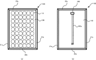
- the solar cell module 100 includes a solar cell panel 101 and a frame 102.
- the solar battery panel 101 is a panel configured to connect a plurality of solar battery cells 110 in series and parallel to obtain necessary voltages and currents.
- Solar cell 110 may be a crystalline silicon cell.
- Solar cell 110 is a member that converts light energy into electric power using the photovoltaic effect, and is arranged so that the light receiving surfaces all face the same direction.
- the light receiving surface of the solar battery cell 110 that is, the light receiving surface of the solar cell module 100 may be referred to as a surface.
- the surface opposite to the light receiving surface of the solar cell module (hereinafter referred to as the anti-light receiving surface) may be referred to as the back surface.
- the light-receiving surface side of the solar cell module 100 may be expressed as an upper side, and the anti-light-receiving surface side may be expressed as a lower side.
- Solar cell 110 is disposed so that the light receiving surface faces upward.
- the surface of each solar cell 110 is connected to the adjacent solar cell 110 by the bus bar electrode 120.
- the joined body of the plurality of solar cells 110 connected by the bus bar electrode 120 has a rectangular shape as a whole. However, the joined body of the solar battery cells 110 may be rectangular or may be square.
- the end of the bus bar electrode 120 is connected to an output terminal housed in a terminal box (not shown).
- the joined body of the plurality of solar battery cells 110 is sandwiched between the glass plate 130 and the back sheet 140 via the filler F.
- the glass plate 130 is disposed on the light receiving surface side of the solar cell 110 and protects the solar cell 110.
- the back sheet 140 is disposed on the side opposite to the light receiving surface of the solar cell 110 and supports the solar cell 110 and the glass plate 130.
- the glass plate 130 and the back sheet 140 have the same shape as the joined body of the solar battery cells 110. In this embodiment, it is a rectangle.
- the frame 102 is a member that holds the end of the laminated body of the solar battery cells 110, the glass plate 130, and the back sheet 140, that is, the periphery via the sealing material 150.
- As the sealant 150 an acrylic or silicon resin can be used.
- the frame 102 can be an aluminum frame. As shown in FIGS. 2A and 2B, the frame 102 includes a pair of long frame members 21a and 21b and a pair of short frame members 22a and 22b.
- the frame 102 forms a rectangle in a top view by these four side frame members 21a, 21b, 22a, and 22b. That is, the longitudinal frame members 21a and 21b are provided so as to face each other with the laminated body interposed therebetween. Further, the short frame members 22a and 22b are connected to the ends of the long frame members 21a and 21b, respectively, and are provided so as to face each other through the laminate.
- the frame 102 has groove portions 102a and 102b.
- a protrusion 102c is interposed between the groove portions 102a and 102b.
- the solar cell panel 101 is inserted into the groove 102a.
- the frame 102 is a member having a U-shaped cross section as a whole, and has adjacent groove portions 102a and 102b on the bottom surface.
- the groove portion 102 a is a groove portion defined by the side surface of the protrusion 102 c on the light receiving surface side, the inner surface of the frame 102 facing the side surface on the light receiving surface side, and the inner bottom surface of the frame 102.
- the groove portion 102 b is a groove portion defined by the side surface on the side opposite to the light receiving surface of the protrusion 102 c, the inner side surface on the side opposite to the light receiving surface of the frame 102 facing the side surface, and the inner bottom surface of the frame 102.
- the protrusion 102c is a member in contact with the side opposite to the light receiving surface of the solar cell module 100 as described later.
- the long frame members 21a and 21b and the short frame members 22a and 22b are arranged so that the surfaces forming the bottom surfaces of the groove portions 102a and 102b face each other.
- the frame 102 is in contact with the side surface of the laminate through the sealing material 150 on the bottom surface of the groove 102a.
- the inner surface on the light receiving surface side of the frame 102 is in contact with the upper surface of the laminate.
- the side surface on the light receiving surface side of the protrusion 102c is in contact with the lower surface of the stacked body.
- the edge part of a laminated body is clamped via the sealing material 150 by the groove part 102a.
- the protective material mentioned later is attached to the clearance gap produced between the back sheet 140 and the side surface by the side of the anti-light-receiving surface of the groove part 102b.
- a junction box 160 is installed on the back sheet 140 on the back surface of the solar cell module 100.
- the junction box 160 is a relay point for taking out the output power of the solar battery cell 110.
- the junction box 160 is installed closer to the short frame member 22 a of the frame 102 than the center portion of the back sheet 140.
- the installation position of the junction box 160 is not limited to a specific location.
- the junction box 160 may be connected with a cable 160a used for connection between the solar cell module 100 and a control device such as an inverter.
- the joined body of the solar battery cells 110, the laminated body of the glass plate 130 and the back sheet 140 has mechanical strength by holding the outer frame by the frame 102.
- the laminated body since there is no member for holding the central portion of the laminated body, for example, when a vibration or impact during transportation is applied to the glass plate 130, the laminated body is easily bent, and as a result, cracks and microcracks are generated in the solar cells 110.
- support members 11, 12, and 13 which are protective materials for protecting the laminated body from below, are attached to a gap generated between the back sheet 140 and the side surface on the side opposite to the light receiving surface of the groove portion of the frame 102.
- the structure of the support members 11, 12, and 13 will be described in detail.
- the support members 11, 12, and 13 are rectangular parallelepiped members, and are disposed perpendicular to the long frame members 21a and 21b and parallel to the short frame members 22a and 22b.
- the support members 11, 12, and 13 have a length in the long side direction substantially equal to a distance between the longitudinal frame members 21a and 21b.
- the lengths of the support members 11, 12, and 13 in the long side direction substantially coincide with the distance between the bottom surfaces of the groove portions 102b of the longitudinal frame members 21a and 21b. That is, the support members 11, 12, and 13 have a length that can be fitted into the space between the opposed longitudinal frame members 21 a and 21 b of the frame 102.
- the thicknesses of the support members 11, 12, and 13 substantially match the distance between the side surface of the groove 102 b of the frame 102 on the side opposite to the light receiving surface of the protrusion 102 c and the inner side surface on the side opposite to the light receiving surface of the frame 102.
- Support members 11, 12, and 13 have a thickness that can be fitted into groove 102b.
- FIG. 3B shows a case where the support members 11, 12, and 13 are formed to have a thickness that comes into contact with a part of the back sheet 140 by elastic force when fitted into the groove 102 b.
- a gap may be formed between the support member 12 and the back sheet 140.
- the rectangular support members 11, 12, and 13 may be solid or hollow.
- the support members 11, 12, and 13 can be made of cardboard sheets, for example. Corrugated cardboard has a low material cost and a low processing cost as a waste material.
- the support members 11, 12, and 13 may be formed by stacking corrugated cardboard sheets, or may be formed by assembling corrugated cardboard sheets into a box shape. Further, as the support members 11, 12, and 13, molded products such as foamed polystyrene, urethane resin, and plastic resin, rubber, and the like, and combinations thereof may be used.
- the support members 11, 12, and 13 are attached to the groove 102 b of the frame 102 on the side opposite to the light receiving surface of the solar cell module 100. That is, the support members 11, 12, and 13 are fixed by being sandwiched between the frames 102. Specifically, the support members 11, 12, and 13 are fixed by being sandwiched between the longitudinal frame members 21 a and 21 b of the frame 102. The support members 11, 12, and 13 are fixed so that a part of the support members 11, 12, and 13 is in contact with the back sheet 140 on the upper surface and the lower surface is in close contact with the side surface of the groove 102 b of the frame 102. Note that the support members 11, 12, and 13 are not necessarily in contact with part of the back sheet 140, and a gap corresponding to the thickness of the protrusion 102 c may be formed.
- the support member 12 is fixed so as to cross the central portion in the longitudinal direction of the back sheet 140 from one longitudinal frame member 21a toward the other longitudinal frame member 21b.
- the support member 11 is disposed via the support member 12 and a space, and traverses an intermediate portion between the support member 12 and the short frame member 22a from the long frame member 21a toward the long frame member 21b.
- the support member 13 is arranged through the space with the support member 12, and traverses the intermediate portion between the support member 12 and the short frame member 22b from the long frame member 21a toward the long frame member 21b.
- the junction box 160 is attached from the center of the back sheet 140 toward the short frame member 22a. Accordingly, the support member 11 crosses the intermediate portion between the support member 12 and the short frame member 22a without being blocked by the junction box 160.
- the cable 160a When the cable 160a is connected to the junction box 160, it can be wound around the junction box 160 and fixed with an adhesive tape or the like.
- the support members 11, 12, and 13 may be disposed at positions corresponding to the ground holes 31 or the attachment holes 32 and 33 of the solar cell module 100.
- the ground hole 31 is a hole for fixing a ground wire such as a copper wire with a fixture or the like in order to ground the solar cell module 100.
- the grounding hole 31 can be provided in the center part of the longitudinal frame members 21a and 21b, for example.
- the attachment holes 32 and 33 are holes into which a fixture or the like is inserted in order to attach the solar cell module 100 to the roof of the house.
- the attachment hole 32 can be provided on the short frame member 22a side in the long frame members 21a and 21b, for example.
- the attachment hole 32 is provided at an intermediate position between the grounding hole 31 and the short frame member 22a.
- the solar cell module 100 may further be provided with an attachment hole at an intermediate position between the attachment hole 32 and the short frame member 22a.
- the attachment hole 33 can be provided in the short frame member 22b side in the long frame members 21a and 21b, for example.
- the attachment hole 33 is provided at an intermediate position between the grounding hole 31 and the short frame member 22b.
- the solar cell module 100 may further be provided with an attachment hole at an intermediate position between the attachment hole 33 and the short frame member 22b.
- the arrangement positions and the number of the grounding holes 31 and the mounting holes 32 and 33 are not limited to the above, and the grounding holes and mounting holes provided in the frame 102 can be used as appropriate.
- a drainage hole can also be used.
- the support members 11 and 13 may be provided at positions relative to the mounting holes 32 and 33, respectively.
- the center positions of the support members 11 and 13 in the short side direction when viewed from above can be arranged together with the attachment holes 32 and 33, respectively.
- the support member 12 can be provided at a position with reference to the grounding hole 31.
- the center position of the support member 12 in the short side direction when viewed from above can be arranged along with the grounding hole 31.
- a marker indicating the center position in the lateral direction in a top view is attached to the support members 11, 12, and 13, and the marker and the grounding hole 31 or the mounting holes 32 and 33 are arranged so as to coincide with each other. Also good.
- the support members 11, 12, and 13 may be arranged without using a grounding hole or the like provided in the frame 102.
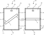
- FIGS. 4A and 4B show a method of fixing the support members 11, 12, and 13 to the solar cell module 100.
- a method of fixing the support member 12 will be described.
- the support member 12 is disposed so as to be inclined with respect to the short frame members 22 a and 22 b of the frame 102.
- the support member 12 may be arranged so that the center portion in the longitudinal direction is positioned at the center portion of the back sheet 140.
- the support member 12 is rotated so as to be parallel to the short frame members 22a and 22b while being in close contact with the back sheet 140. That is, in a state where the longitudinal central portion of the support member 12 is fixed, the support member 12 is moved so that one end is closer to the longitudinal frame member 21a and the other end is closer to the longitudinal frame member 21b. As described above, the length of the support member 12 is the same as the distance between the longitudinal frame members 21a and 21b. Therefore, both ends of the support member 12 abut against the longitudinal frame members 21a and 21b by rotation. Then, as shown in FIG. 4B, both ends of the support member 12 are sandwiched and fixed between the opposing inner side surfaces of the groove portions 102b of the longitudinal frame members 21a and 21b.
- the protective material of the present embodiment is a protective material for the solar cell module 100 having the solar cell panel 101 in which the glass plate 130 is laminated on the light receiving surface side and the rectangular frame 102 that holds the solar cell panel 101.
- the support member 12 is disposed on the side opposite to the light receiving surface of the solar cell module 100, and the support member 12 is sandwiched and fixed between the opposing frame members 21 a and 21 b of the frame 102.
- the support member 12 supports the side opposite to the light receiving surface of the solar cell module 100, it is possible to suppress the occurrence of microcracks by suppressing the displacement of the glass plate 130 due to vibration or impact that occurs during transportation of the solar cell module 100. .
- the support member 12 fixed to the groove portion 102c of the frame 102 is in contact with or not in contact with part of the back sheet 140.
- the back sheet 140 of the bent solar cell module 100 comes into contact with the support member 12 and the two are in close contact with each other. Therefore, the support member 12 supports the solar cell module 100 from the lower surface, and suppresses the displacement of the glass plate 130.
- the support member 12 can be fixed simply by being sandwiched between the longitudinal frame members 21a and 21b of the frame, it is easy to attach and remove.
- the entire solar cell module 100 is not packed, but includes only a portion that supports the center of the solar cell module 100 and a portion that fixes the solar cell module 100 to the solar cell module 100. Can be reduced.
- the protective material of the solar cell module which can reduce cost and an operation man-hour can be provided.
- the support member 11 On the side opposite to the light receiving surface of the solar cell module 100, the support member 11 disposed between the support member 12 and one frame member 22 a of the frame 102, the support member 12, and the other frame of the frame 102 A support member 13 disposed between the support member 11 and the member 22b.
- the support members 11 and 13 are sandwiched and fixed between two opposing frame members 21a and 21b of the frame 102.
- the support member 11 supports between the support member 12 and the short frame member 22a and the support member 13 supports between the support member 12 and the short frame member 22b, the support member is evenly provided on the back surface of the solar cell module 100. 11, 12, 13 can be arranged. Therefore, the occurrence of microcracks can be reduced by further suppressing the displacement of the glass plate 130 due to vibrations and impacts that occur during transportation of the solar cell module 100. Since the support members 11 and 13 can be fixed simply by being sandwiched between the longitudinal frame members 21a and 21b of the frame, attachment and removal are facilitated.
- the support members 11, 12, 13 are arranged at positions corresponding to the ground holes 31 or the mounting holes 32, 33 provided in the frame 102.
- the support members 11, 12, 13 By arranging the support members 11, 12, 13 at positions corresponding to the grounding holes 31 or the mounting holes 32, 33, it is possible to reduce the work of position confirmation when attaching the support members 11, 12, 13.
- the attachment positions in the solar cell modules 100 can be the same. Therefore, it can be stabilized when the solar cell module 100 is loaded and transported.
- the mounting holes 32 and 33 are determined in consideration of the strength against snow load, wind pressure, and the like. Therefore, the solar cell panel 101 can be evenly supported by disposing the support members 11, 12, and 13 at positions corresponding to the grounding hole 31 and the mounting holes 32 and 33 located at the center. Become.
- the support members 11, 12, and 13 have a length substantially equal to the distance between the two opposing longitudinal frame members 21a and 21b arranged perpendicular to the support members 11, 12, and 13 of the frame 102. ing.
- the protective material can be easily applied to the solar cell module 100. Can be fixed to.
- the support members 11, 12, and 13 are made of cardboard sheets. Thereby, the material cost can be reduced and the waste material processing cost can be reduced.
- the protective material of the solar cell module 100 according to the second embodiment will be described with reference to FIG. Only differences from the above-described embodiment will be described, and the same parts as those of the above-described embodiment will be denoted by the same reference numerals and detailed description thereof will be omitted.
- the solar cell module 100 of the present embodiment is packed with a packing body 40 that is attached with support members 11, 12, and 13 and is a protective material.
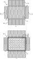
- the packaging body 40 is a cross-shaped member, and is formed of a corrugated cardboard sheet.
- the package 40 has a bottom surface 41, long side surfaces 42a and 42b, and short side surfaces 43a and 43b.
- the bottom surface 41 is rectangular, and has a rectangular shape formed by the frame 102 of the solar cell module 100, that is, a size that substantially matches the outer periphery. Therefore, the bottom surface 41 has a size that can cover the anti-light-receiving surface that is the lower surface of the solar cell module 100.
- the bottom surface 41 of this embodiment is rectangular.
- the long side surfaces 42 a and 42 b are formed continuously with the long side of the bottom surface 41.
- the short side surfaces 43 a and 43 b are continuously formed on the short side of the bottom surface 41.
- the boundary lines of the bottom surface 41, the long side surfaces 42a and 42b, and the short side surfaces 43a and 43b are formed to be bendable.
- the long side surfaces 42a and 42b and the short side surfaces 43a and 43b each have a fold line 44.
- the respective boundary lines of the long side surfaces 42 a and 42 b and the short side surfaces 43 a and 43 b and the lengths up to the folding line 44 substantially match the thickness of the frame 102 of the solar cell module 100.
- the length from the fold line 44 to the end of the long side surfaces 42a, 42b is substantially equal to half the length of the frame 102 of the solar cell module 100 in the short direction.
- the length from the fold line 44 to the end of the short side surfaces 43a and 43b can be set as appropriate, but is at least a length that can cover a part of the light receiving surface of the solar cell module 100.
- the solar cell module 100 when the solar cell module 100 to which the support members 11, 12, and 13 are attached is packed with the packing body 40, the solar cell module 100 is first set so that the anti-light-receiving surface is in contact with the bottom surface 41. It is placed on the bottom surface 41 of the package 40. Then, the short side surfaces 43a and 43b are respectively bent upward. Furthermore, it bends so that it may go inward of the solar cell module 100 with the bending line 44.
- the long side surfaces 42a and 42b are respectively bent upward. Furthermore, it bends so that it may go inward of the solar cell module 100 with the bending line 44.
- FIG. Therefore, the region from the boundary line of the long side surfaces 42 a and 42 b to the folding line 44 covers the side surface in the longitudinal direction of the solar cell module 100.
- region from the fold line 44 to the edge part of the longitudinal side surfaces 42a and 42b covers the light-receiving surface of the longitudinal direction of a solar cell module, ie, an upper surface. That is, the end of the long side surface 42 a and the end of the long side surface 42 b face each other at the center position in the short direction of the solar cell module 100.
- the anti-light-receiving surface is in contact with the bottom surface 41.
- the light-receiving surface is placed in contact with the bottom surface 41, and the long side surfaces 42a and 42b and the short side surfaces 43a and 43b are anti-light-receiving.
- the surface may be covered.
- the surface in contact with the bottom surface 41 is the bottom surface, and the surface covered by the long side surfaces 42a and 42b and the short side surfaces 43a and 43b is the top surface.
- the protective material of the present embodiment further includes a package 40 of the solar cell module 100, and the package 40 has a rectangular bottom surface 41 that covers the lower surface of the solar cell module 100, one side surface of the solar cell module 100, and The other end of the bottom surface 41 covering the side surfaces 43a and 43b continuously formed from one end of the bottom surface 41, covering at least a part of the top surface, and the other both side surfaces and the top surface of the solar cell module 100. Side surfaces 42a and 42b formed continuously from each of the portions.
- the bottom surface 41 is in contact with the lower surface of the solar cell module 100, and the long side surfaces 42a and 42b and the short side surfaces 43a and 43b cover the side surface and the upper surface of the solar cell module 100. Therefore, since the periphery of the solar cell module 100 is completely packed, it is possible to suppress external factors such as vibration, impact, and scratches that are generated when the solar cell module 100 is transported. Further, when the solar cell modules 100 are loaded, the solar cell modules 100 can be brought into close contact with each other, and stable transportation can be performed.
- the protective material of the solar cell module 100 according to the third embodiment will be described with reference to FIG. Only differences from the above-described embodiment will be described, and the same parts as those of the above-described embodiment will be denoted by the same reference numerals and detailed description thereof will be omitted.
- the solar cell module 100 of the present embodiment is packed with a packing body 50 which is attached with support members 11, 12 and 13 and is a protective material.
- the packing body 50 is a rectangular member and is formed of a corrugated cardboard sheet.
- the package 50 has a bottom surface 51 and longitudinal side surfaces 52a and 52b.
- the bottom surface 51 is rectangular and has a rectangular shape formed by the frame 102 of the solar cell module 100, that is, a size that substantially matches the outer periphery. Therefore, the bottom surface 51 has a size capable of covering the light receiving surface that is the top surface of the solar cell module 100.
- the bottom surface 41 of this embodiment is rectangular.
- the long side surfaces 52 a and 52 b are formed continuously with the long side of the bottom surface 41.
- the boundary lines between the bottom surface 51 and the long side surfaces 52a and 52b are formed to be bendable.
- the respective boundary lines between the bottom surface 51 and the long side surfaces 52a and 52b and the lengths to the ends of the long side surfaces 52a and 52b substantially match the thickness of the frame 102 of the solar cell module 100.
- the solar cell module 100 to which the support members 11, 12, and 13 are attached is packed with the packing body 50
- the solar cell module 100 is first packed so that the light receiving surface is in contact with the bottom surface 51. It is placed on the bottom surface 51 of the body 50. Then, the long side surfaces 45a and 52b are respectively bent upward. Therefore, the region from the boundary line of the long side surfaces 52 a and 52 b to the end of the long side surfaces 52 a and 52 b covers the side surface in the longitudinal direction of the solar cell module 100.
- the example in which the light receiving surface is installed in contact with the bottom surface 51 has been described.
- This configuration has the purpose of protecting the glass plate 130 from vibration and impact.
- the anti-light receiving surface may be placed so as to be in contact with the bottom surface 51. That is, in this embodiment, the surface that contacts the bottom surface 51 is the top surface.
- the protective material of the present embodiment further includes a package 50 of the solar cell module 100, and the package 50 includes a rectangular bottom surface 51 that covers the top surface of the solar cell module 100 and one side surface of the solar cell module 100. And side surfaces 52a and 52b continuously formed from one end of the bottom surface 51.
- the bottom surface 51 is in contact with the top surface of the solar cell module 100, and the long side surfaces 52a and 52b cover the side surface of the solar cell module 100. Therefore, the solar cell module 100 can be packed with a small packing material while covering the glass surface of the solar cell module 100. Therefore, it is possible to suppress external factors such as vibration, impact, and scratches that occur during transportation of the solar cell module 100. Moreover, the cost concerning a packaging material can be reduced. When compared with the second embodiment, the capacity of the solar cell module 100 including the package 50 can be reduced. Further, when the solar cell modules 100 are loaded, the solar cell modules 100 can be brought into close contact with each other, and stable transportation can be performed.
- the package of the solar cell module 100 according to the fourth embodiment will be described with reference to FIG. Only differences from the above-described embodiment will be described, and the same parts as those of the above-described embodiment will be denoted by the same reference numerals and detailed description thereof will be omitted.
- the solar cell module 100 of the present embodiment has the support members 11, 12, and 13 attached thereto and is packed by a packing body 40 or 50.
- FIG. 7 illustrates an example in which the solar cell module 100 is packed by the packing body 50, the same configuration can be applied when the packing body 40 is used.
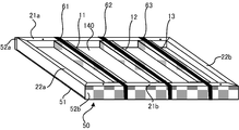
- the solar cell module 100 packed in the packing body 50 is bound to the packing body 50 by bands 61, 62, 63 which are protective materials.
- Bands 61, 62, and 63 can be made of polypropylene or nylon tape.
- the bands 61, 62, and 63 are bundled so as to be disposed at positions where the support members 11, 12, and 13 are attached.
- the band 61 bundles the outer peripheral surface of the packing material 50 and the upper surface of the support member 11.
- the band 62 bundles the outer peripheral surface of the packing material 50 and the upper surface of the support member 12.
- the band 63 bundles the outer peripheral surface of the packing material 50 and the upper surface of the support member 13.
- the protective material of the present embodiment includes bands 61, 62, and 63 that bind the packing body 50 and the solar cell module 100, and the bands 61, 62, and 63 are positions where the support members 11, 12, and 13 are attached. Placed in.
- the bands 61, 62, and 63 it is possible to bind the packing body 50 and the solar cell module 100 and more reliably suppress vibrations and impacts that occur during transportation of the solar cell module 100.
- the bands 61, 62, and 63 are disposed at positions where the support members 11, 12, and 13 are attached, the bands 61, 62, and 63 do not bend. Therefore, it becomes possible to fix the packing body 50 and the solar cell module 100 in a closely contacted state. Therefore, when the solar cell module 100 is loaded, the solar cell modules 100 can be brought into close contact with each other, and stable transportation can be performed.
- FIG. 8 illustrates an example in which the solar cell module 100 is packed by the packing body 50, the same configuration can be applied when the packing body 40 is used.
- the solar cell module 100A is placed on the upper surface of the pallet 70.
- the pallet 70 is a loading platform on which the solar cell modules 100 are placed when the plurality of solar cell modules 100 are transported.
- Solar cell module 100A is arranged so that glass plate 130 faces upward. That is, the solar cell module 100A is arranged such that the pallet 70 and the support members 11, 12, 13 of the solar cell module 100A face each other.
- the solar cell module 100B is stacked on the upper surface of the frame 102 on the glass plate 130 side of the solar cell module 100A via the packing material 50.
- the solar cell module 100B is arranged so that the glass plate 130 faces upward. That is, the solar cell module 100B is disposed so that the glass plate 130 of the solar cell module 100A and the support members 11, 12, 13 of the solar cell module 100B face each other. Similarly, solar cell modules 100C and 100D are stacked. On the upper surface of the frame 102 on the glass plate 130 side of the solar cell module 100D, the solar cell module 100E is stacked via the packing material 50.
- the solar cell module 100E is arranged so that the support members 11, 12, and 13 face upward. That is, the solar cell module 100B is arranged so that the glass plate 130 of the solar cell module 100A and the glass plate 130 of the solar cell module 100B face each other. That is, only the uppermost solar cell module 100E is arranged such that the glass plate 130 faces downward. Therefore, the solar cell modules 100D and 100E are opposed to each other through the packing material 50.
- the solar cell modules 100A, 100B, 100C, 100D, and 100E loaded as described above are bound together by bands 61, 62, and 63.
- the bands 61, 62, and 63 are bundled so as to be disposed at positions where the support members 11, 12, and 13 are attached.
- the band 62 includes an upper surface of the support member 12 of the solar cell module 100E, a side surface of the packaging material 50 of the solar cell modules 100A, 100B, 100C, 100D, and 100E, a lower surface of the pallet 70, Bundle.
- the protective material of the present embodiment has a plurality of packing bodies 50 in which the solar cell modules 100 are packed, and among the plurality of stacked packing bodies 50, the uppermost packing body 50 is the glass plate 130 of the solar cell module 100E.
- the packaging bodies 50 other than the uppermost packaging body 50 are disposed so that the glass plates 130 of the solar cell modules 100A, 100B, 100C, and 100D face upward.
- the uppermost packaging body 50 is arranged so that the glass plates 130 of the solar cell module 100E face downward, so that the glass plates 130 of the solar cell modules 100D and 100E are in close contact with each other, and vibrations are alleviated. Therefore, even when the package 50 is loaded, it is possible to suppress vibrations and impacts that occur during transportation of the solar cell module.
- the support members 11, 12, 13 of the solar cell module 100E are arranged to face upward. Therefore, it becomes easy for the operator to confirm the positions of the support members 11, 12, 13 when arranging the bands 61, 62, 63 at the positions where the support members 11, 12, 13 are attached. Therefore, workability can be improved.
- the bands 61, 62, and 63 are arranged at positions where the support members 11, 12, and 13 are attached, the support members 11, 12, and 13 of the plurality of solar cell modules 100 are integrated, respectively.
- a plurality of solar cell modules 100 are supported. Therefore, the bending of the glass plate 130 during transportation can be reduced.
- the configuration in which the support members 11, 12, and 13 are provided has been described.
- the number of support members is not limited to three.
- it can be provided at the center position of the longitudinal frame members 21a and 21b.
- the center positions of the longitudinal frame members 21a and 21b may be disposed.
- four or more support members may be provided.
- the support members 11, 12, and 13 may be fixed so as to be sandwiched between the short frame members 22a and 22b.
- the length of the support member 11 in the longitudinal direction can be set to a length substantially equal to the distance between the short frame members 22a and 22b.
- the support members 11, 12, and 13 are fitted into a gap that is generated between the back sheet 140 and the side surface of the groove portion of the frame 102.
- the frame 102 does not necessarily have a groove. It is good also as a structure fitted between the planes of the longitudinal frame members 21a and 21b of the frame 102. That is, at least the end surfaces of the supporting members 11, 12, and 13 need only be sandwiched and fixed between the longitudinal frame members 21a and 21b, and whether or not the side surfaces are fixed may be appropriately designed.
- the solar cells arranged in a rectangular shape have been described.
- the solar cells may be arranged in a polygonal or square shape, for example.
- the glass plate 130, the back sheet 140, and the frame 102 may be used in accordance with the shape formed by the plurality of solar cells.
- SYMBOLS 100 Solar cell module 101 ... Solar cell panel 102 ... Frame 102a, 102b ... Groove 102c ... Protrusion 110 ... Solar cell 120 ... Bus bar electrode 130 ... Glass plate 140 ... Back sheet 150 ... Sealing material 160 ... Junction box 160a ... Cable F ... Fillers 11, 12, 13 ... Support members 21a, 21b ... Long frame members 22a, 22b ... Short frame members 31 ... Grounding holes 32, 33 ... Mounting holes 40, 50 ... Packing bodies 41, 51 ... Bottom surfaces 42a, 42b , 52a, 52b ... long side surfaces 43a, 43b ... short side surfaces 44 ... bending lines 61, 62, 63 ... bands 70 ... pallets
Landscapes
- Engineering & Computer Science (AREA)
- Mechanical Engineering (AREA)
- Packaging Frangible Articles (AREA)
Abstract
太陽電池モジュールの輸送時に発生する振動や衝撃を抑制するとともに、コストおよび作業工数を低減することができる太陽電池モジュールの保護材を提供する。受光面側にガラス板130が積層された太陽電池パネル101と、太陽電池パネル101を保持する矩形のフレーム102とを有する太陽電池モジュール100の保護材であって、太陽電池モジュール100の反受光面側の中央部に配置された支持部材12を有し、支持部材12は、フレーム102の対向する2つの枠部材21a,21bに挟み込まれて固定される。
Description
本発明の実施形態は、太陽電池モジュールを保護する保護材に関する。
太陽電池モジュールは、太陽電池パネルおよびフレームを有する。太陽電池パネルは、複数の太陽電池セルを直並列接続して、必要な電圧と電流を得られるように構成したパネルである。太陽電池セルは、光起電力効果を利用して光エネルギーを電力に変換する部材である。太陽電池セルの受光面には、ガラス等の透過性基板が積層されている。このような太陽電池セルを複数有する太陽電池パネルが、例えば矩形のフレームに嵌め込まれ、太陽電池モジュールが構成される。
太陽電池モジュールは、住宅用の太陽電池モジュールと産業用の太陽電池モジュールに大別される。住宅用の太陽電池モジュールは、一般住宅等に適用される太陽電池モジュールである。産業用の太陽電池モジュールは、大規模な商業施設や公共機関等に適用される太陽電池モジュールである。産業用の太陽電池モジュールは、出荷数が多いことから、複数の太陽電池モジュールを1つの梱包体内に積層することにより集合梱包されている。
ところで、産業用の太陽電池モジュールは、住宅用の太陽電池モジュールと比較してサイズが大きく、大量生産されていることから低価格である。そこで、この産業用の太陽電池モジュールを一般住宅に適用したいという要望があった。しかし、一般住宅に対して産業用の太陽電池モジュールを販売する場合、太陽電池モジュールは住宅ごとに輸送されることとなる。そうなると、設置枚数によっては、集合梱包に収まらず端数が発生する可能性がある。また、集合梱包は重量も大きく、荷降ろしの際にフォークリフトを使用できない場合がある。
以上より、産業用の太陽電池モジュールを1枚ずつ個別に梱包することが求められていた。しかし、産業用の太陽電池モジュールはサイズが大きいことから、個別梱包の場合、太陽電池モジュールのガラス板が振動や衝撃により撓みやすくなる。また、個別梱包は集合梱包よりも多量の梱包材が必要になることから、梱包材料の費用が増加し、梱包作業及び開封作業にも時間が掛かる。さらに、開封後には廃材となった梱包材料の処理費用も発生する。
本発明の実施形態は、上記の課題を解決することを目的とする。すなわち、太陽電池モジュールの輸送時に発生する振動や衝撃を抑制するとともに、コストおよび作業工数を低減することができる太陽電池モジュールの保護材を提供することを目的とする。
本実施形態の保護材は、受光面側にガラス板が積層された太陽電池パネルと、前記太陽電池パネルを保持する矩形のフレームとを有する太陽電池モジュールの保護材であって、前記太陽電池モジュールの反受光面側に配置された第一の支持部材を有し、前記第一の支持部材は、前記フレームの対向する2つの枠部材に挟み込まれて固定される。
以下、実施形態の太陽電池モジュールの保護材について、図面を参照して説明する。
[第1の実施形態]
[1.構成]
(太陽電池モジュール)
本実施形態の保護材が適用される太陽電池モジュールは、特定の種類に限られない。以下では、太陽電池モジュールの一例として、結晶シリコン系太陽電池モジュールについて説明する。
[1.構成]
(太陽電池モジュール)
本実施形態の保護材が適用される太陽電池モジュールは、特定の種類に限られない。以下では、太陽電池モジュールの一例として、結晶シリコン系太陽電池モジュールについて説明する。
図1に示す太陽電池モジュール100は、いわゆるスーパーストレート型と呼ばれる結晶シリコン系太陽電池モジュールである。太陽電池モジュール100は、太陽電池パネル101およびフレーム102を有する。太陽電池パネル101は、複数の太陽電池セル110を直並列接続して、必要な電圧と電流を得られるように構成したパネルである。太陽電池セル110は、結晶シリコンセルとすることができる。
太陽電池セル110は、光起電力効果を利用して光エネルギーを電力に変換する部材であり、受光面が全て同一方向を向くように配置される。以下の説明では、太陽電池セル110の受光面、すなわち太陽電池モジュール100の受光面を表面という場合がある。太陽電池モジュールの受光面と反対側の面(以下、反受光面という)を裏面という場合がある。また、太陽電池モジュール100の受光面側を上側と表現し、反受光面側を下側と表現する場合がある。
太陽電池セル110は、受光面が上向きになるように配置される。各太陽電池セル110の表面は、隣接する太陽電池セル110とバスバー電極120で接続されている。バスバー電極120で接続された複数の太陽電池セル110の接合体は、全体として長方形となる。ただし、太陽電池セル110の接合体は矩形であればよく、正方形であっても良い。バスバー電極120の端部は、不図示の端子箱に収納された出力端子に接続されている。
複数の太陽電池セル110の接合体は、充填材Fを介して、ガラス板130とバックシート140に挟み込まれている。ガラス板130は太陽電池セル110の受光面側に配置され太陽電池セル110を保護する。バックシート140は太陽電池セル110の反受光面側に配置され、太陽電池セル110及びガラス板130を支持する。ガラス板130及びバックシート140は、太陽電池セル110の接合体と同様の形状を有している。本実施形態では、長方形である。
フレーム102は、太陽電池セル110の接合体、ガラス板130及びバックシート140の積層体の端部、すなわち周囲を、シール材150を介して保持する部材である。シール材150としては、アクリル系やシリコン系の樹脂などを用いることができる。フレーム102は、アルミフレームとすることができる。図2(a)および(b)に示す通り、フレーム102は、一対の長手枠部材21a,21bと一対の短手枠部材22a,22bとを含む。フレーム102は、これらの4辺の枠部材21a,21b,22a,および22bにより、上面視で長方形を形成している。すなわち、長手枠部材21a,21bは、積層体を介して対向するように設けられている。また、短手枠部材22a,22bは、それぞれ長手枠部材21a,21bの端部に接続され、積層体を介して対向するように設けられている。
また、図1に示す通り、フレーム102は、溝部102a、102bを有する。溝部102a、102bの間には、突起102cが介在している。溝部102aには、太陽電池パネル101が差し込まれる構造となっている。具体的には、フレーム102は、全体としては断面U字型の部材であり、隣接する溝部102a,102bを底面に有する。溝部102aは、突起102cの受光面側の側面と、この側面と対向するフレーム102の受光面側の内側面と、フレーム102の内底面により画成される溝部である。溝部102bは、突起102cの反受光面側の側面と、この側面と対向するフレーム102の反受光面側の内側面と、フレーム102の内底面により画成される溝部である。突起102cは、後述の通り太陽電池モジュール100の反受光面側に接する部材である。
長手枠部材21a,21bおよび短手枠部材22a,22bは、溝部102a,102bの底面を形成する面が対向するように配置されている。フレーム102は、溝部102aの底面において、シール材150を介して積層体の側面に接する。溝部102aは、フレーム102の受光面側の内側面が、積層体の上面に接する。また、溝部102aは、突起102cの受光面側の側面が、積層体の下面に接する。このようにして積層体の端部は、溝部102aにより、シール材150を介して挟持される。そして、バックシート140と溝部102bの反受光面側の側面との間に生じる隙間に、後述する保護材が取り付けられる。
図2(b)に示すように、太陽電池モジュール100の裏面において、ジャンクションボックス160が、バックシート140に設置されている。ジャンクションボックス160は、太陽電池セル110の出力電力を取出すための中継点である。ジャンクションボックス160は、バックシート140の中心部よりもフレーム102の短手枠部材22a寄りに設置されている。ただし、ジャンクションボックス160の設置位置は特定の箇所に限定されるものではない。また、ジャンクションボックス160には、太陽電池モジュール100と、インバータ等の制御装置との接続に用いられるケーブル160aが接続されていても良い。
上記のように、太陽電池セル110の接合体、ガラス板130及びバックシート140の積層体は、外枠がフレーム102で保持されることにより、機械的強度をもたせている。一方、積層体の中心部を保持する部材がない為、例えば輸送時の振動や衝撃がガラス板130に加わると、積層体が撓みやすくなり、結果として太陽電池セル110に割れやマイクロクラックを発生させる可能性がある。そこで、バックシート140とフレーム102の溝部の反受光面側の側面と間に生じる隙間に、積層体を下方から保護する保護材である支持部材11,12,13を取り付ける。以下、支持部材11,12,13の構成を詳述する。
(支持部材の構成)
図3(a)に示す通り、支持部材11,12,13は、長方体状の部材であり、長手枠部材21a,21bと垂直かつ短手枠部材22a,22bと平行に配置される。支持部材11,12,13は、長辺方向の長さが、長手枠部材21a,21bの間の距離と略一致する。具体的には、支持部材11,12,13の長辺方向の長さは、長手枠部材21a,21bの溝部102bの底面間の距離と略一致する。すなわち、支持部材11,12,13は、フレーム102の対向する長手枠部材21a,21bの間の空間にはめ込まれることができる長さを有する。
図3(a)に示す通り、支持部材11,12,13は、長方体状の部材であり、長手枠部材21a,21bと垂直かつ短手枠部材22a,22bと平行に配置される。支持部材11,12,13は、長辺方向の長さが、長手枠部材21a,21bの間の距離と略一致する。具体的には、支持部材11,12,13の長辺方向の長さは、長手枠部材21a,21bの溝部102bの底面間の距離と略一致する。すなわち、支持部材11,12,13は、フレーム102の対向する長手枠部材21a,21bの間の空間にはめ込まれることができる長さを有する。
また、支持部材11,12,13の厚みは、フレーム102の溝部102bにおける、突起102cの反受光面側の側面と、フレーム102の反受光面側の内側面との間の距離と略一致する。支持部材11,12,13は、溝部102bに嵌め込まれることができる厚みを有する。図3(b)は、支持部材11,12,13が、溝部102bに嵌め込まれた時に、弾性力によりバックシート140の一部に接触する厚みに形成された場合を示す。ただし、図3(c)に示すように、支持部材12とバックシート140との間に隙間が生じていても良い。長方体状の支持部材11,12,13は、中実であっても中空であっても良い。
支持部材11,12,13は、例えば、段ボールシートで構成することができる。段ボールシートは材料費が安価であり、廃材としての処理費用も少ない。支持部材11,12,13は、段ボールシートを積層して形成しても良いし、段ボールシートを箱型に組み立てて形成しても良い。また、支持部材11,12,13として、発泡スチロール、ウレタン樹脂、プラスチック樹脂等の成形品や、ゴム等、およびこれらの組み合わせを用いても良い。
(支持部材の固定態様)
図3(b)および(c)に示すように、支持部材11,12,13は、太陽電池モジュール100の反受光面側において、フレーム102の溝部102bに取り付けられる。すなわち、支持部材11,12,13は、フレーム102に挟み込まれて固定される。具体的には、支持部材11,12,13は、フレーム102の長手枠部材21a,21bに挟み込まれて固定される。支持部材11,12,13は、上面でバックシート140に一部接触し、下面がフレーム102の溝部102bの側面に密着するように固定される。なお、支持部材11,12,13は、必ずしもバックシート140の一部に接触する必要はなく、突起102cの厚みに対応する隙間が生じていても良い。
図3(b)および(c)に示すように、支持部材11,12,13は、太陽電池モジュール100の反受光面側において、フレーム102の溝部102bに取り付けられる。すなわち、支持部材11,12,13は、フレーム102に挟み込まれて固定される。具体的には、支持部材11,12,13は、フレーム102の長手枠部材21a,21bに挟み込まれて固定される。支持部材11,12,13は、上面でバックシート140に一部接触し、下面がフレーム102の溝部102bの側面に密着するように固定される。なお、支持部材11,12,13は、必ずしもバックシート140の一部に接触する必要はなく、突起102cの厚みに対応する隙間が生じていても良い。
支持部材12は一方の長手枠部材21aから他方の長手枠部材21bに向かって、バックシート140の長手方向中央部を横断するように固定される。支持部材11は、支持部材12と空間を介して配置され、長手枠部材21aから長手枠部材21bに向かって、支持部材12と短手枠部材22aの間において中間部分を横断する。同様に、支持部材13は、支持部材12と空間を介して配置され、長手枠部材21aから長手枠部材21bに向かって、支持部材12と短手枠部材22bの間において中間部分を横断する。
ジャンクションボックス160は、バックシート140の中心部から短手枠部材22a寄りに取り付けられている。よって、ジャンクションボックス160に妨げられず、支持部材11は、支持部材12と短手枠部材22aの間において中間部分を横断する。ジャンクションボックス160にケーブル160aが接続されている場合には、ジャンクションボックス160の周囲に巻きつけて粘着テープ等で固定することができる。
(支持部材の配置態様)
図3(a)に示す通り、支持部材11,12,13は、太陽電池モジュール100の接地穴31又は取付穴32,33に対応する位置に配置されていても良い。接地穴31は、太陽電池モジュール100を接地するために、銅線等の接地線を固定具等により固定する穴である。接地穴31は、例えば、長手枠部材21a,21bの中心部分に設けることができる。
図3(a)に示す通り、支持部材11,12,13は、太陽電池モジュール100の接地穴31又は取付穴32,33に対応する位置に配置されていても良い。接地穴31は、太陽電池モジュール100を接地するために、銅線等の接地線を固定具等により固定する穴である。接地穴31は、例えば、長手枠部材21a,21bの中心部分に設けることができる。
取付穴32,33は、太陽電池モジュール100を家屋の屋根に取り付けるために、固定具等が挿入される穴である。取付穴32は、例えば、長手枠部材21a,21bにおいて、短手枠部材22a側に設けることができる。取付穴32は、接地穴31と短手枠部材22aの間の中間位置に設けられている。なお、太陽電池モジュール100には、取付穴32と短手枠部材22aの間の中間位置に、さらに取付穴が設けられていても良い。
また、取付穴33は、例えば、長手枠部材21a,21bにおいて、短手枠部材22b側に設けることができる。取付穴33は、接地穴31と短手枠部材22bの間の中間位置に設けられている。なお、太陽電池モジュール100には、取付穴33と短手枠部材22bの間の中間位置に、さらに取付穴が設けられていても良い。また、接地穴31と取付穴32,33の配置位置や個数は、上記に限定されず、フレーム102に適宜設けられている接地穴および取付穴を適宜利用することができる。また、排水穴も利用することができる。
支持部材11,13は、それぞれ取付穴32,33を基準とした位置に設けても良い。たとえば、支持部材11,13の、上面視における短手方向の中心位置を、それぞれ取付穴32,33に併せて配置することができる。支持部材12は、接地穴31を基準とした位置に設けることができる。たとえば、支持部材12の、上面視における短手方向の中心位置を、接地穴31に併せて配置することができる。支持部材11,12,13に、上面視における短手方向の中心位置を示すマーカーを付しておき、このマーカーと接地穴31又は取付穴32,33の位置が一致するように配置する構成としてもよい。ただし、フレーム102に設けられている接地穴等を利用せずに、支持部材11,12,13を配置しても良い。
(支持部材の固定方法)
図4(a)および(b)に、支持部材11,12,13の、太陽電池モジュール100への固定方法を示す。ここでは、例として、支持部材12の固定方法を説明する。支持部材12を太陽電池モジュール100に固定する場合、まず、支持部材12の上面を、バックシート140に密着させる。図4(a)に示す通り、支持部材12は、フレーム102の短手枠部材22a,22bに対して斜めに傾くように配置される。また、支持部材12の長手方向中央部がバックシート140の中心部に位置するように配置すると良い。
図4(a)および(b)に、支持部材11,12,13の、太陽電池モジュール100への固定方法を示す。ここでは、例として、支持部材12の固定方法を説明する。支持部材12を太陽電池モジュール100に固定する場合、まず、支持部材12の上面を、バックシート140に密着させる。図4(a)に示す通り、支持部材12は、フレーム102の短手枠部材22a,22bに対して斜めに傾くように配置される。また、支持部材12の長手方向中央部がバックシート140の中心部に位置するように配置すると良い。
次に、支持部材12をバックシート140に密着させたまま、短手枠部材22a,22bに平行になるように回転させる。すなわち、支持部材12の長手方向中央部を固定した状態で、一端を長手枠部材21aに、他端を長手枠部材21bに近づけるように移動させる。上述の通り、支持部材12の長さは、長手枠部材21aと21bの間の距離と同じである。よって、支持部材12の両端は、回転によりそれぞれ長手枠部材21a,21bに突き当たる。すると、図4(b)に示す通り、支持部材12の両端は長手枠部材21a,21bの溝部102bの対向する内側面に挟み込まれ、固定される。
[2.作用効果]
(1)本実施形態の保護材は、受光面側にガラス板130が積層された太陽電池パネル101と、太陽電池パネル101を保持する矩形のフレーム102とを有する太陽電池モジュール100の保護材であって、太陽電池モジュール100の反受光面側に配置された支持部材12を有し、支持部材12は、フレーム102の対向する枠部材21a,21bに挟み込まれて固定される。
(1)本実施形態の保護材は、受光面側にガラス板130が積層された太陽電池パネル101と、太陽電池パネル101を保持する矩形のフレーム102とを有する太陽電池モジュール100の保護材であって、太陽電池モジュール100の反受光面側に配置された支持部材12を有し、支持部材12は、フレーム102の対向する枠部材21a,21bに挟み込まれて固定される。
支持部材12が太陽電池モジュール100の反受光面側を支持するので、太陽電池モジュール100の輸送時に発生する振動や衝撃によるガラス板130の変位を抑制してマイクロクラックの発生を低減することができる。具体的には、フレーム102の溝部102cに固定された支持部材12は、バックシート140の一部に接触しているかまたは接触していない状態である。太陽電池モジュール100が振動等により撓んだ場合には、撓んだ太陽電池モジュール100のバックシート140が支持部材12に接触して両者が密着した状態となる。従って、支持部材12は、太陽電池モジュール100を下面から支持することとなり、ガラス板130の変位を抑制する。
支持部材12をフレームの長手枠部材21a,21bに挟み込むだけで固定できるので、取り付け及び取り外しが容易となる。また、太陽電池モジュール100全体を梱包するのではなく、太陽電池モジュール100の中心部を支持する部分と、その部分を太陽電池モジュール100に固定する部分のみからなるので、梱包材料費及び廃材処理費用を低減することができる。以上より、太陽電池モジュールの輸送時に発生する振動や衝撃を抑制するとともに、コストおよび作業工数を低減することができる太陽電池モジュールの保護材を提供することができる。
(2)太陽電池モジュール100の反受光面側において、支持部材12と、フレーム102の一方の枠部材22aとの間に配置された支持部材11と、支持部材12と、フレーム102の他方の枠部材22bとの間に配置された支持部材13と、を有し、支持部材11,13は、フレーム102の対向する2つの枠部材21a,21bに挟み込まれて固定される。
支持部材11が支持部材12と短手枠部材22aの間を、支持部材13が支持部材12と短手枠部材22bの間を支持するので、太陽電池モジュール100の裏面に、均等に、支持部材11,12,13を配置することができる。従って、さらに太陽電池モジュール100の輸送時に発生する振動や衝撃によるガラス板130の変位を抑制してマイクロクラックの発生を低減することができる。支持部材11,13をフレームの長手枠部材21a,21bに挟み込むだけで固定できるので、取り付け及び取り外しが容易となる
(3)支持部材11,12,13が、フレーム102に設けられた接地穴31または取付穴32,33に対応する位置に配置される。
支持部材11,12,13を、接地穴31又は取付穴32,33に対応する位置に配置することで、支持部材11,12,13を取り付ける際に位置確認の作業を減らすことができる。また、複数の太陽電池モジュール100に支持部材11,12,13を取り付ける場合、各太陽電池モジュール100における取り付け位置を同じとすることができる。そのため、太陽電池モジュール100を積載して輸送する際に安定させることができる。さらに、取付穴32,33は、積雪荷重や風圧等に対する強度を考慮した上で決定されている。従って、中央に位置する接地穴31と、これらの取付穴32,33に対応する位置に、支持部材11,12,13を配置することで、太陽電池パネル101を均等に支持することが可能となる。
(4)支持部材11,12,13は、フレーム102の、支持部材11,12,13と垂直に配置される対向する2つの長手枠部材21a,21b間の距離と略等しい長さを有している。
支持部材11,12,13を短手枠部材22a,22bに対して斜めに差し込み、それから短手枠部材22a,22bと平行になるように回転させるだけで、保護材を太陽電池モジュール100に容易に固定することができる。
(5)支持部材11,12,13は、段ボールシートで構成されている。これによって、材料費を安価にし、かつ廃材の処理費用も低減することができる。
[第2の実施形態]
[1.構成]
第2の実施形態に係る太陽電池モジュール100の保護材について、図5を参照して説明する。なお、前述の実施形態とは異なる点のみを説明し、前述の実施形態と同じ部分については同じ符号を付して詳細な説明は省略する。本実施形態の太陽電池モジュール100は、支持部材11,12,13が取り付けられ、かつ保護材である梱包体40により梱包されている。
[1.構成]
第2の実施形態に係る太陽電池モジュール100の保護材について、図5を参照して説明する。なお、前述の実施形態とは異なる点のみを説明し、前述の実施形態と同じ部分については同じ符号を付して詳細な説明は省略する。本実施形態の太陽電池モジュール100は、支持部材11,12,13が取り付けられ、かつ保護材である梱包体40により梱包されている。
図5(a)に示す通り、梱包体40は、十字状の部材であり、段ボールシートで形成されている。梱包体40は、底面41、長手側面42a,42b、短手側面43a,43bを有する。底面41は、矩形であり、太陽電池モジュール100のフレーム102が形成する矩形状、すなわち外周と略一致する大きさである。従って、底面41は、太陽電池モジュール100の下面である反受光面を覆うことができる大きさを有する。本実施形態の底面41は、長方形状とする。
長手側面42a,42bは、底面41の長辺に連続して形成されている。短手側面43a、43bは、底面41の短辺に連続して形成されている。底面41と、長手側面42a,42bおよび短手側面43a、43bのそれぞれの境界線は、折り曲げ可能に形成されている。また、長手側面42a,42bおよび短手側面43a、43bは、それぞれ折り曲げ線44を有する。長手側面42a,42bおよび短手側面43a、43bのそれぞれの境界線と、折り曲げ線44までの長さは、太陽電池モジュール100のフレーム102の厚みと略一致する。
長手側面42a,42bの折り曲げ線44から端部までの長さは、太陽電池モジュール100のフレーム102の短手方向の長さの半分に略一致する。短手側面43a,43bの折り曲げ線44から端部までの長さは、適宜設定可能であるが、少なくとも太陽電池モジュール100の受光面の一部を覆うことができる長さとする。
図5(b)に示す通り、支持部材11,12,13が取り付けられた太陽電池モジュール100を、梱包体40で梱包する場合、まず反受光面が底面41に接するように太陽電池モジュール100を梱包体40の底面41に載置する。そして、短手側面43a、43bを、それぞれ上方に向かって折り曲げる。さらに、折り曲げ線44にて太陽電池モジュール100の内方に向かうように折り曲げる。よって、短手側面43a、43bの境界線から折り曲げ線44までの領域が、太陽電池モジュール100の短手方向の側面を覆う。また、折り曲げ線44から短手側面43a、43bまでの領域が、太陽電池モジュール100の短手方向の受光面、すなわち上面の一部を覆う。
次に、長手側面42a,42bを、それぞれ上方に向かって折り曲げる。さらに、折り曲げ線44にて太陽電池モジュール100の内方に向かうように折り曲げる。よって、長手側面42a、42bの境界線から折り曲げ線44までの領域が、太陽電池モジュール100の長手方向の側面を覆う。また、折り曲げ線44から長手側面42a、42bの端部までの領域が、太陽電池モジュールの長手方向の受光面、すなわち上面を覆う。すなわち、長手側面42aの端部と長手側面42bの端部とが、太陽電池モジュール100の短手方向の中心位置で対向する。
なお、上記では反受光面が底面41に接するように設置する例を説明したが、受光面が底面41に接するように載置し、長手側面42a,42bおよび短手側面43a、43bが反受光面を覆うようにしても良い。すなわち、本実施形態では、底面41に接する面を下面とし、長手側面42a,42bおよび短手側面43a、43bが覆う面を上面とする。
[2.作用効果]
本実施形態の保護材は、太陽電池モジュール100の梱包体40をさらに有し、梱包体40は、太陽電池モジュール100の下面を覆う矩形の底面41と、太陽電池モジュール100の一方の両側面および少なくとも上面の一部を覆う、底面41の一方の端部のそれぞれから連続して形成された側面43a,43bと、太陽電池モジュール100の他方の両側面および上面を覆う、底面41の他方の端部のそれぞれから連続して形成された側面42a,42bと、を有する。
本実施形態の保護材は、太陽電池モジュール100の梱包体40をさらに有し、梱包体40は、太陽電池モジュール100の下面を覆う矩形の底面41と、太陽電池モジュール100の一方の両側面および少なくとも上面の一部を覆う、底面41の一方の端部のそれぞれから連続して形成された側面43a,43bと、太陽電池モジュール100の他方の両側面および上面を覆う、底面41の他方の端部のそれぞれから連続して形成された側面42a,42bと、を有する。
底面41が太陽電池モジュール100の下面に接し、長手側面42a,42bおよび短手側面43a、43bが太陽電池モジュール100の側面および上面を覆う。従って、太陽電池モジュール100の周囲が完全に梱包されるため、太陽電池モジュール100の輸送時に発生する振動や衝撃、およびキズが付くなどの外的要因を抑制することが可能となる。また、太陽電池モジュール100が積載される場合に、太陽電池モジュール100間を密着させることができ、安定した輸送を行うことができる。
[第3の実施形態]
[1.構成]
第3の実施形態に係る太陽電池モジュール100の保護材について、図6を参照して説明する。なお、前述の実施形態とは異なる点のみを説明し、前述の実施形態と同じ部分については同じ符号を付して詳細な説明は省略する。本実施形態の太陽電池モジュール100は、支持部材11,12,13が取り付けられ、かつ保護材である梱包体50により梱包されている。
[1.構成]
第3の実施形態に係る太陽電池モジュール100の保護材について、図6を参照して説明する。なお、前述の実施形態とは異なる点のみを説明し、前述の実施形態と同じ部分については同じ符号を付して詳細な説明は省略する。本実施形態の太陽電池モジュール100は、支持部材11,12,13が取り付けられ、かつ保護材である梱包体50により梱包されている。
図6(a)に示す通り、梱包体50は、長方形状の部材であり、段ボールシートで形成されている。梱包体50は、底面51、長手側面52a,52bを有する。底面51は、矩形であり、太陽電池モジュール100のフレーム102が形成する矩形状、すなわち外周と略一致する大きさである。従って、底面51は、太陽電池モジュール100の上面である受光面を覆うことができる大きさを有する。本実施形態の底面41は、長方形状とする。
長手側面52a,52bは、底面41の長辺に連続して形成されている。底面51と、長手側面52a,52bのそれぞれの境界線は、折り曲げ可能に形成されている。底面51と長手側面52a,52bのそれぞれの境界線と、長手側面52a,52bの端部までの長さは、太陽電池モジュール100のフレーム102の厚みと略一致する。
図5(b)に示す通り、支持部材11,12,13が取り付けられた太陽電池モジュール100を、梱包体50で梱包する場合、まず受光面が底面51に接するように太陽電池モジュール100を梱包体50の底面51に載置する。そして、長手側面45a,52bを、それぞれ上方に向かって折り曲げる。よって、長手側面52a、52bの境界線から、長手側面52a,52bの端部までの領域が、太陽電池モジュール100の長手方向の側面を覆う。
なお、上記では受光面が底面51に接するように設置する例を説明した。この構成には、振動や衝撃から、ガラス板130を保護する目的がある。ただし、反受光面が底面51に接するように載置しても良い。すなわち、本実施形態では、底面51に接する面を上面とする。
[2.作用効果]
本実施形態の保護材は、太陽電池モジュール100の梱包体50をさらに有し、梱包体50は、太陽電池モジュール100の上面を覆う矩形の底面51と、太陽電池モジュール100の一方の両側面を覆う、底面51の一方の端部のそれぞれから連続して形成された側面52a,52bと、を有する。
本実施形態の保護材は、太陽電池モジュール100の梱包体50をさらに有し、梱包体50は、太陽電池モジュール100の上面を覆う矩形の底面51と、太陽電池モジュール100の一方の両側面を覆う、底面51の一方の端部のそれぞれから連続して形成された側面52a,52bと、を有する。
底面51が太陽電池モジュール100の上面に接し、長手側面52a,52bが太陽電池モジュール100の側面を覆う。従って、太陽電池モジュール100のガラス面を覆いつつ少ない梱包材料で太陽電池モジュール100を梱包することができる。よって、太陽電池モジュール100の輸送時に発生する振動や衝撃、およびキズが付くなどの外的要因を抑制することが可能となる。また、梱包材にかかるコストを削減することができる。第2の実施形態と比較した場合、梱包体50を含めた太陽電池モジュール100の容量を減らすことができる。さらに、太陽電池モジュール100が積載される場合に、太陽電池モジュール100間を密着させることができ、安定した輸送を行うことができる。
[第4の実施形態]
[1.構成]
第4の実施形態に係る太陽電池モジュール100の梱包体について、図7を参照して説明する。なお、前述の実施形態とは異なる点のみを説明し、前述の実施形態と同じ部分については同じ符号を付して詳細な説明は省略する。本実施形態の太陽電池モジュール100は、支持部材11,12,13が取り付けられ、かつ梱包体40または50により梱包されている。図7では、太陽電池モジュール100が梱包体50により梱包されている例を説明するが、梱包体40を用いた場合も同様の構成を適用することができる。
[1.構成]
第4の実施形態に係る太陽電池モジュール100の梱包体について、図7を参照して説明する。なお、前述の実施形態とは異なる点のみを説明し、前述の実施形態と同じ部分については同じ符号を付して詳細な説明は省略する。本実施形態の太陽電池モジュール100は、支持部材11,12,13が取り付けられ、かつ梱包体40または50により梱包されている。図7では、太陽電池モジュール100が梱包体50により梱包されている例を説明するが、梱包体40を用いた場合も同様の構成を適用することができる。
梱包体50に梱包された太陽電池モジュール100は、保護材であるバンド61,62,63により、梱包体50と結束されている。バンド61,62,63は、ポリプロピレンやナイロン製のテープを用いることができる。バンド61,62,63は、支持部材11,12,13が取り付けられている位置に配置されるように結束されている。
具体的には、バンド61は、梱包材50の外周面と、支持部材11の上面を束ねる。バンド62は、梱包材50の外周面と、支持部材12の上面を束ねる。バンド63は、梱包材50の外周面と、支持部材13の上面を束ねる。
[2.作用効果]
本実施形態の保護材は、梱包体50と太陽電池モジュール100を結束するバンド61,62,63を有し、バンド61,62,63は、支持部材11,12,13が取り付けられている位置に配置される。
本実施形態の保護材は、梱包体50と太陽電池モジュール100を結束するバンド61,62,63を有し、バンド61,62,63は、支持部材11,12,13が取り付けられている位置に配置される。
バンド61,62,63により、梱包体50と太陽電池モジュール100を結束し、より確実に太陽電池モジュール100の輸送時に発生する振動や衝撃を抑制することが可能となる。特に、バンド61,62,63は、支持部材11,12,13が取り付けられている位置に配置されるため、バンド61,62,63に撓みが生じることがない。従って、梱包体50と太陽電池モジュール100とを密着した状態で固定することが可能となる。そのため、太陽電池モジュール100が積載される場合に、太陽電池モジュール100間を密着させることができ、安定した輸送を行うことができる。
[第5の実施形態]
[1.構成]
第5の実施形態に係る太陽電池モジュール100の梱包体について、図8を参照して説明する。なお、前述の実施形態とは異なる点のみを説明し、前述の実施形態と同じ部分については同じ符号を付して詳細な説明は省略する。本実施形態では、梱包体50に梱包された太陽電池モジュール100A,100B,100C,100D,100Eが、パレット70上に積載されている。図8では、太陽電池モジュール100が梱包体50により梱包されている例を説明するが、梱包体40を用いた場合も同様の構成を適用することができる。
[1.構成]
第5の実施形態に係る太陽電池モジュール100の梱包体について、図8を参照して説明する。なお、前述の実施形態とは異なる点のみを説明し、前述の実施形態と同じ部分については同じ符号を付して詳細な説明は省略する。本実施形態では、梱包体50に梱包された太陽電池モジュール100A,100B,100C,100D,100Eが、パレット70上に積載されている。図8では、太陽電池モジュール100が梱包体50により梱包されている例を説明するが、梱包体40を用いた場合も同様の構成を適用することができる。
太陽電池モジュール100Aは、パレット70の上面に載置されている。パレット70は、複数の太陽電池モジュール100を輸送する際に、太陽電池モジュール100が載置される荷台である。太陽電池モジュール100Aは、ガラス板130が上方を向くように配置されている。すなわち、太陽電池モジュール100Aは、パレット70と太陽電池モジュール100Aの支持部材11,12,13が対向するように配置されている。太陽電池モジュール100Aのガラス板130側のフレーム102の上面には、梱包材50を介して、太陽電池モジュール100Bが積載されている。
太陽電池モジュール100Bは、ガラス板130が上方を向くように配置されている。すなわち、太陽電池モジュール100Bは、太陽電池モジュール100Aのガラス板130と、太陽電池モジュール100Bの支持部材11,12,13が対向するように配置されている。同様にして、太陽電池モジュール100Cおよび100Dが積載されている。太陽電池モジュール100Dのガラス板130側のフレーム102の上面には、梱包材50を介して、太陽電池モジュール100Eが積載されている。
太陽電池モジュールモジュール100Eは、支持部材11,12,13が上方を向くように配置されている。すなわち、太陽電池モジュール100Bは、太陽電池モジュール100Aのガラス板130と太陽電池モジュール100Bのガラス板130が対向するように配置されている。すなわち、最上段の太陽電池モジュール100Eのみ、ガラス板130が下方を向くように配置されている。従って、太陽電池モジュール100Dと100Eは、それぞれの梱包材50を介して対向することとなる。
以上のようにして積載された太陽電池モジュール100A,100B,100C,100D,100Eは、バンド61,62,63により結束されている。バンド61,62,63は、支持部材11,12,13が取り付けられている位置に配置されるように結束されている。例えば、図7に示す通り、バンド62は、太陽電池モジュール100Eの支持部材12の上面と、太陽電池モジュール100A,100B,100C,100D,100Eの梱包材50の側面と、パレット70の下面と、を束ねる。
[2.作用効果]
本実施形態の保護材は、太陽電池モジュール100を梱包した梱包体50が複数積載され、複数積載された梱包体50のうち、最上段の梱包体50は、太陽電池モジュール100Eのガラス板130が下方を向くように配置され、最上段の梱包体50以外の梱包体50は、太陽電池モジュール100A,100B,100C,100Dのガラス板130が上方を向くように配置されている。
本実施形態の保護材は、太陽電池モジュール100を梱包した梱包体50が複数積載され、複数積載された梱包体50のうち、最上段の梱包体50は、太陽電池モジュール100Eのガラス板130が下方を向くように配置され、最上段の梱包体50以外の梱包体50は、太陽電池モジュール100A,100B,100C,100Dのガラス板130が上方を向くように配置されている。
最上段の梱包体50は、太陽電池モジュール100Eのガラス板130が下方を向くように配置されることにより、太陽電池モジュール100Dと100Eのガラス板130同士が密着され、振動が緩和される。従って、梱包体50が積載された場合であっても、太陽電池モジュールの輸送時に発生する振動や衝撃を抑制することが可能となる。
太陽電池モジュール100Eの支持部材11,12,13は上方を向くように配置されている。従って、作業者が、バンド61,62,63を、支持部材11,12,13が取り付けられている位置に配置する際に、支持部材11,12,13の位置を確認しやすくなる。従って、作業性を向上させることができる。
また、バンド61,62,63を、支持部材11,12,13が取り付けられている位置に配置することで、複数の太陽電池モジュール100の支持部材11,12,13がそれぞれ一体化され支柱のように複数の太陽電池モジュール100を支える。従って、輸送時のガラス板130の撓みを軽減させることができる。
[その他の実施形態]
(1)上記の実施形態では、支持部材11,12,13を設ける構成を説明したが、支持部材の本数は3本に限定されない。例えば、1本の場合は、長手枠部材21a,21bの中心位置に設けることができる。また、2本の場合には、長手枠部材21a,21bの中心位置を挟むように配置すればよい。もちろん、4本以上の支持部材を設けても良い。
(1)上記の実施形態では、支持部材11,12,13を設ける構成を説明したが、支持部材の本数は3本に限定されない。例えば、1本の場合は、長手枠部材21a,21bの中心位置に設けることができる。また、2本の場合には、長手枠部材21a,21bの中心位置を挟むように配置すればよい。もちろん、4本以上の支持部材を設けても良い。
(2)また、支持部材11,12,13を短手枠部材22a,22bに挟み込まれるように固定しても良い。その場合は、支持部材11の長手方向の長さを、短手枠部材22a,22b間の距離と略等しい長さとすることができる。
(3)上記の実施形態では、支持部材11,12,13は、バックシート140とフレーム102の溝部の側面と間に生じる隙間にはめ込まれている。ただし、フレーム102は必ずしも溝部を有している必要はない。フレーム102の長手枠部材21a,21bの平面間にはめ込まれる構成としても良い。すなわち、支持部材11,12,13は少なくとも端面が長手枠部材21a,21bに挟み込まれて固定されていればよく、側面を固定するか否かは適宜設計すれば良い。
(4)上述の実施形態では複数の太陽電池セルを長方形状に並べたものを説明したが、例えば多角形や正方形になるように並べても良い。ガラス板130、バックシート140及びフレーム102は、複数の太陽電池セルが形成する形状に合わせたものを用いれば良い。
本発明のいくつかの複数の実施形態を説明したが、これらの実施形態は例として提示したものであって、発明の範囲を限定することを意図していない。これら実施形態は、その他の様々な形態で実施されることが可能であり、発明の要旨を逸脱しない範囲で、種々の省略や置き換え、変更を行うことができる。これらの実施形態やその変形は、発明の範囲や要旨に含まれると同様に、特許請求の範囲に記載された発明とその均等の範囲に含まれるものである。
100…太陽電池モジュール
101…太陽電池パネル
102…フレーム
102a,102b…溝部
102c…突起
110…太陽電池セル
120…バスバー電極
130…ガラス板
140…バックシート
150…シール材
160…ジャンクションボックス
160a…ケーブル
F…充填剤
11,12,13…支持部材
21a,21b…長手枠部材
22a,22b…短手枠部材
31…接地穴
32,33…取付穴
40,50…梱包体
41,51…底面
42a,42b,52a,52b…長手側面
43a,43b…短手側面
44…折り曲げ線
61,62,63…バンド
70…パレット
101…太陽電池パネル
102…フレーム
102a,102b…溝部
102c…突起
110…太陽電池セル
120…バスバー電極
130…ガラス板
140…バックシート
150…シール材
160…ジャンクションボックス
160a…ケーブル
F…充填剤
11,12,13…支持部材
21a,21b…長手枠部材
22a,22b…短手枠部材
31…接地穴
32,33…取付穴
40,50…梱包体
41,51…底面
42a,42b,52a,52b…長手側面
43a,43b…短手側面
44…折り曲げ線
61,62,63…バンド
70…パレット
Claims (9)
- 受光面側にガラス板が積層された太陽電池パネルと、前記太陽電池パネルを保持する矩形のフレームとを有する太陽電池モジュールの保護材であって、
前記太陽電池モジュールの反受光面側に配置された第一の支持部材を有し、
前記第一の支持部材は、前記フレームの対向する2つの枠部材に挟み込まれて固定される太陽電池モジュールの保護材。 - 前記太陽電池モジュールの反受光面側において、前記第一の支持部材と、前記フレームの一方の枠部材との間に配置された第二の支持部材と、
前記第一の支持部材と、前記フレームの他方の枠部材との間に配置された第三の支持部材と、を有し、
前記第二および第三の支持部材は、前記フレームの対向する2つの枠部材に挟み込まれて固定される請求項1記載の太陽電池モジュールの保護材。 - 前記第一、第二、および第三の支持部材が、前記フレームに設けられた接地穴または取付穴に対応する位置に配置される請求項1又は2記載の太陽電池モジュールの保護材。
- 前記第一、第二、および第三の支持部材は、前記フレームの、前記支持部材と垂直に配置される対向する2つの枠部材間の距離と略等しい長さを有する請求項1~3いずれか一項記載の太陽電池モジュールの保護材。
- 前記第一、第二、および第三の支持部材は、段ボールシートで構成されている請求項1~4のいずれか一項に記載の太陽電池モジュールの保護材。
- 太陽電池モジュールの梱包体をさらに有し、
前記梱包体は、
前記太陽電池モジュールの下面を覆う矩形の底面と、
前記太陽電池モジュールの一方の両側面および少なくとも上面の一部を覆う、前記底面の一方の端部のそれぞれから連続して形成された第一の側面と、
前記太陽電池モジュールの他方の両側面および上面を覆う、前記底面の他方の端部のそれぞれから連続して形成された第二の側面と、を有する請求項1~5いずれか一項記載の太陽電池モジュールの保護材。 - 太陽電池モジュールの梱包体をさらに有し、
前記梱包体は、
前記太陽電池モジュールの上面を覆う矩形の底面と、
前記太陽電池モジュールの一方の両側面を覆う、前記底面の一方の端部のそれぞれから連続して形成された第一の側面と、を有する請求項1~5いずれか一項記載の太陽電池モジュールの保護材。 - 前記太陽電池モジュールを梱包した前記梱包体が複数積載され、
複数積載された前記梱包体のうち、最上段の梱包体は、前記太陽電池モジュールのガラス板が下方を向くように配置され、
前記最上段の梱包体以外の梱包体は、前記太陽電池モジュールのガラス板が上方を向くように配置されている請求項6又は7記載の太陽電池モジュールの保護材。 - 前記梱包体と前記太陽電池モジュールを結束するバンドを有し、
前記バンドは、前記支持部材が取り付けられている位置に配置される請求項6~8いずれか一項記載の太陽電池モジュールの保護材。
Priority Applications (1)
| Application Number | Priority Date | Filing Date | Title |
|---|---|---|---|
| PCT/JP2015/069416 WO2017006414A1 (ja) | 2015-07-06 | 2015-07-06 | 太陽電池モジュールの保護材 |
Applications Claiming Priority (1)
| Application Number | Priority Date | Filing Date | Title |
|---|---|---|---|
| PCT/JP2015/069416 WO2017006414A1 (ja) | 2015-07-06 | 2015-07-06 | 太陽電池モジュールの保護材 |
Publications (1)
| Publication Number | Publication Date |
|---|---|
| WO2017006414A1 true WO2017006414A1 (ja) | 2017-01-12 |
Family
ID=57686177
Family Applications (1)
| Application Number | Title | Priority Date | Filing Date |
|---|---|---|---|
| PCT/JP2015/069416 Ceased WO2017006414A1 (ja) | 2015-07-06 | 2015-07-06 | 太陽電池モジュールの保護材 |
Country Status (1)
| Country | Link |
|---|---|
| WO (1) | WO2017006414A1 (ja) |
Citations (3)
| Publication number | Priority date | Publication date | Assignee | Title |
|---|---|---|---|---|
| JP2011240933A (ja) * | 2010-05-14 | 2011-12-01 | Mitsubishi Heavy Ind Ltd | 梱包構造および積層梱包構造 |
| JP2013244981A (ja) * | 2012-05-25 | 2013-12-09 | Sanyo Electric Co Ltd | 梱包材 |
| JP2015070033A (ja) * | 2013-09-27 | 2015-04-13 | 三洋電機株式会社 | 太陽電池モジュール及び太陽電池モジュールの製造方法 |
-
2015
- 2015-07-06 WO PCT/JP2015/069416 patent/WO2017006414A1/ja not_active Ceased
Patent Citations (3)
| Publication number | Priority date | Publication date | Assignee | Title |
|---|---|---|---|---|
| JP2011240933A (ja) * | 2010-05-14 | 2011-12-01 | Mitsubishi Heavy Ind Ltd | 梱包構造および積層梱包構造 |
| JP2013244981A (ja) * | 2012-05-25 | 2013-12-09 | Sanyo Electric Co Ltd | 梱包材 |
| JP2015070033A (ja) * | 2013-09-27 | 2015-04-13 | 三洋電機株式会社 | 太陽電池モジュール及び太陽電池モジュールの製造方法 |
Similar Documents
| Publication | Publication Date | Title |
|---|---|---|
| JP5208548B2 (ja) | バッテリパック、バッテリパックの梱包方法および組立て方法 | |
| US9928965B2 (en) | Electricity storage module | |
| EP3252848B1 (en) | Cell device, cell unit, and cell device installation method | |
| KR101269973B1 (ko) | 전지 | |
| CN101156249A (zh) | 太阳能电池元件的捆包方法及太阳能电池元件的捆包体 | |
| CN102569692A (zh) | 电池组件保护结构 | |
| JPWO2017195289A1 (ja) | 太陽光発電装置、太陽電池パドルおよび宇宙構造物 | |
| JP2011240933A (ja) | 梱包構造および積層梱包構造 | |
| CN102414834B (zh) | 太阳能电池组件 | |
| EP2460184A1 (en) | Solar battery assembly | |
| JP2014031191A (ja) | 梱包具 | |
| JP6072915B2 (ja) | 太陽電池モジュール梱包体及び太陽電池モジュールの梱包方法 | |
| JP6830264B2 (ja) | 太陽電池モジュール、その梱包形態、及び、太陽光発電装置 | |
| JP4745859B2 (ja) | 太陽電池パネルの梱包箱、及び太陽電池パネルの梱包方法 | |
| JP2013129444A (ja) | 保持構造体 | |
| JP6470657B2 (ja) | 太陽電池モジュール梱包体 | |
| JP6015905B2 (ja) | 梱包材 | |
| JP5127844B2 (ja) | 太陽電池素子の梱包体、および太陽電池素子の梱包方法 | |
| JP6607395B2 (ja) | 太陽電池モジュール用梱包体および梱包体付き太陽電池モジュール | |
| CN102623525B (zh) | 太阳能电池组件 | |
| JP2016158363A (ja) | 太陽電池モジュール用中敷材 | |
| JP6147396B2 (ja) | 太陽電池モジュール梱包体及び太陽電池モジュールの梱包方法 | |
| JP5914228B2 (ja) | パネル材の梱包用コーナー支持機構 | |
| JP6363395B2 (ja) | 太陽電池モジュールの梱包材 | |
| JP6599003B2 (ja) | 太陽電池モジュール梱包体および梱包材 |
Legal Events
| Date | Code | Title | Description |
|---|---|---|---|
| 121 | Ep: the epo has been informed by wipo that ep was designated in this application |
Ref document number: 15897677 Country of ref document: EP Kind code of ref document: A1 |
|
| NENP | Non-entry into the national phase |
Ref country code: DE |
|
| 122 | Ep: pct application non-entry in european phase |
Ref document number: 15897677 Country of ref document: EP Kind code of ref document: A1 |
|
| NENP | Non-entry into the national phase |
Ref country code: JP |