WO2017002939A1 - 電子制御装置及びスタック使用方法 - Google Patents
電子制御装置及びスタック使用方法 Download PDFInfo
- Publication number
- WO2017002939A1 WO2017002939A1 PCT/JP2016/069511 JP2016069511W WO2017002939A1 WO 2017002939 A1 WO2017002939 A1 WO 2017002939A1 JP 2016069511 W JP2016069511 W JP 2016069511W WO 2017002939 A1 WO2017002939 A1 WO 2017002939A1
- Authority
- WO
- WIPO (PCT)
- Prior art keywords
- task
- electronic control
- stack
- stack area
- control device
- Prior art date
- Legal status (The legal status is an assumption and is not a legal conclusion. Google has not performed a legal analysis and makes no representation as to the accuracy of the status listed.)
- Ceased
Links
Images



Classifications
-
- F—MECHANICAL ENGINEERING; LIGHTING; HEATING; WEAPONS; BLASTING
- F02—COMBUSTION ENGINES; HOT-GAS OR COMBUSTION-PRODUCT ENGINE PLANTS
- F02D—CONTROLLING COMBUSTION ENGINES
- F02D41/00—Electrical control of supply of combustible mixture or its constituents
- F02D41/009—Electrical control of supply of combustible mixture or its constituents using means for generating position or synchronisation signals
-
- G—PHYSICS
- G06—COMPUTING OR CALCULATING; COUNTING
- G06F—ELECTRIC DIGITAL DATA PROCESSING
- G06F9/00—Arrangements for program control, e.g. control units
- G06F9/06—Arrangements for program control, e.g. control units using stored programs, i.e. using an internal store of processing equipment to receive or retain programs
- G06F9/46—Multiprogramming arrangements
- G06F9/48—Program initiating; Program switching, e.g. by interrupt
- G06F9/4806—Task transfer initiation or dispatching
- G06F9/4812—Task transfer initiation or dispatching by interrupt, e.g. masked
-
- F—MECHANICAL ENGINEERING; LIGHTING; HEATING; WEAPONS; BLASTING
- F02—COMBUSTION ENGINES; HOT-GAS OR COMBUSTION-PRODUCT ENGINE PLANTS
- F02D—CONTROLLING COMBUSTION ENGINES
- F02D41/00—Electrical control of supply of combustible mixture or its constituents
- F02D41/24—Electrical control of supply of combustible mixture or its constituents characterised by the use of digital means
- F02D41/26—Electrical control of supply of combustible mixture or its constituents characterised by the use of digital means using computer, e.g. microprocessor
- F02D41/266—Electrical control of supply of combustible mixture or its constituents characterised by the use of digital means using computer, e.g. microprocessor the computer being backed-up or assisted by another circuit, e.g. analogue
-
- F—MECHANICAL ENGINEERING; LIGHTING; HEATING; WEAPONS; BLASTING
- F02—COMBUSTION ENGINES; HOT-GAS OR COMBUSTION-PRODUCT ENGINE PLANTS
- F02D—CONTROLLING COMBUSTION ENGINES
- F02D45/00—Electrical control not provided for in groups F02D41/00 - F02D43/00
-
- G—PHYSICS
- G06—COMPUTING OR CALCULATING; COUNTING
- G06F—ELECTRIC DIGITAL DATA PROCESSING
- G06F9/00—Arrangements for program control, e.g. control units
- G06F9/06—Arrangements for program control, e.g. control units using stored programs, i.e. using an internal store of processing equipment to receive or retain programs
- G06F9/46—Multiprogramming arrangements
- G06F9/50—Allocation of resources, e.g. of the central processing unit [CPU]
- G06F9/5005—Allocation of resources, e.g. of the central processing unit [CPU] to service a request
- G06F9/5027—Allocation of resources, e.g. of the central processing unit [CPU] to service a request the resource being a machine, e.g. CPUs, Servers, Terminals
- G06F9/5038—Allocation of resources, e.g. of the central processing unit [CPU] to service a request the resource being a machine, e.g. CPUs, Servers, Terminals considering the execution order of a plurality of tasks, e.g. taking priority or time dependency constraints into consideration
Definitions
- the present invention relates to an electronic control device that uses a stack area and a stack usage method.
- RAM Random Access Memory
- ASIL Automotive Safety Integrity Level
- the stack data temporarily saved in the stack area by a task to which a high safety level (for example, ASIL-D) is assigned becomes a lower safety level (for example, QM).
- a high safety level for example, ASIL-D
- QM lower safety level
- an electronic control device and a stack usage method capable of strengthening restrictions on access to stack data are provided.
- the electronic control device includes a memory and a processor, and when the processor executes a task, the task is pre-assigned to the task among a plurality of stack areas secured in the memory. Use at least one stack area.
- the electronic control device it is possible to strengthen access restrictions on stack data, thereby realizing functional safety.
- FIG. 1 is a diagram illustrating an embodiment of an electronic control device 100 mounted on an automobile.
- the electronic control device 100 performs various controls of the vehicle, and controls, for example, an internal combustion engine.
- the electronic control device 100 includes a plurality of CPUs (Central Processing Units) 110, a plurality of local memories 120, and a global memory 130.
- CPUs Central Processing Units
- CPU110 can read the detection value etc. of the various sensors connected to the electronic control apparatus 100, and can calculate the target value for vehicle control. Specifically, the CPU 110 receives signals from various sensors including a crank angle sensor, a cam angle sensor, a water temperature sensor, a throttle sensor, an air flow sensor, and an air-fuel ratio sensor (not shown). And CPU110 calculates the data required for various controls, such as an electronically controlled throttle valve, a fuel injection valve, and an ignition coil, with reference to the map for control, for example.
- various controls such as an electronically controlled throttle valve, a fuel injection valve, and an ignition coil
- the CPU 110 is connected to a local memory 120 provided for each CPU 110 and a global memory 130 accessible by all the CPUs 110.
- This local memory 120 corresponds to each CPU 110 on a one-to-one basis, and is used only for execution of the corresponding CPU 110.
- the local memory 120 is provided with a stack area 122 for holding data in a LIFO (Last In First Out) system and other various memory areas.
- LIFO Last In First Out
- the electronic control device 100 has a plurality of modes with different access restrictions to the stack area when executing a task. This access restriction is determined according to a level based on a safety standard. In the present embodiment, there are a supervisor mode (SVM: supervisor mode) and a user mode (UM: user mode) as a plurality of modes, and an access authority is assigned to each mode, thereby realizing access restriction. Yes.
- SVM supervisor mode
- UM user mode
- an access authority is assigned to each mode, thereby realizing access restriction.
- SVM a task whose safety level is ASIL-D, C, B, or A is executed.
- UM a task whose safety level is QM is executed.
- the tasks are classified into groups based on a predetermined rule such as a safety level, and are executed in a mode corresponding to the group.
- the stack area 122 provided in the local memory 120 is divided into two areas, a QM stack area 124 and an ASIL stack area 126. That is, two stack areas are secured in the local memory 120.
- a task to which a UM is assigned can access only the QM stack area 124, and access to the ASIL stack area 126 is prohibited.
- the task to which the SVM is assigned can access the ASIL stack area 126 and the QM stack area 124.
- Such access restriction for each task can be realized by hardware such as a memory management unit.
- two stack areas are secured in the local memory 120, but the electronic control apparatus 100 can secure three or more stack areas in the local memory 120.
- the stack area 122 In the stack area 122, for example, data is stored in a direction in which the address increases. 2 and 3, the upward direction is the direction in which the address value increases.
- memory areas are allocated in the order of the ASIL stack area 126 and the QM stack area 124 from the smallest address.
- the stack area 122 is provided with a stack area of lower importance on the side in which data is stored.
- each stack area 122 is allocated in a direction in which stack data is stored from a stack area having a high degree of importance among the divided stack areas.
- FIG. 2 shows a case where an SVM task is being executed.
- the electronic control unit 100 can arbitrarily switch and use the first stack pointer and the second stack pointer.
- the QM stack area 124 and the ASIL stack area 126 can be accessed.
- FIG. 3 shows a case where a UM task is being executed. In this case, the electronic control unit 100 uses only the second stack pointer. When the UM task is executed, access to the ASIL stack area 126 is prohibited.
- the electronic control unit 100 when the CPU 110 executes a task, at least one stack area is selected from the plurality of stack areas reserved in the local memory 120 as a stack area to be used for the task.
- the At least one stack area used by the task is set for each group in which the task is classified according to a predetermined rule such as a safety level. Thereby, functional safety in the electronic control unit 100 is realized.
- the mode cannot be changed in a direction in which the authority is higher than the assigned mode.
- a UM task cannot change the mode from UM to SVM.
- the electronic control unit 100 may execute a UM task, and accordingly, the mode is switched from SVM to UM.
- the electronic control unit 100 switches the stack pointer to the second stack pointer indicating the most recently stored data in the QM stack area 124 (S102).
- the electronic control unit 100 switches the mode from SVM to UM (S103).
- the electronic control unit 100 executes the UM task and uses the QM stack area 124 as the stack area at that time (S104).
- a target torque calculation task that calculates a target torque from an accelerator opening and calculates a target throttle opening of an electronically controlled throttle based on the target torque.
- a target torque calculation task that calculates a target torque from an accelerator opening and calculates a target throttle opening of an electronically controlled throttle based on the target torque.
- the electronic control unit 100 first reads the output of the accelerator opening from the accelerator pedal sensor. Further, the electronic control unit 100 calculates a target torque from the accelerator opening. Then, the electronic control unit 100 calculates the target throttle opening so that the calculated target torque is obtained, and controls the electronic control throttle based on the target throttle opening.
- the electronic control unit 100 calculates the current torque separately from the target torque, and compares the target torque with the current torque to determine whether an abnormality has occurred.
- the task for making such a determination has a safety level higher than QM (for example, ASIL-C). Therefore, this task cannot be performed by the UM and must be performed by the SVM. Therefore, the electronic control unit 100 issues an interrupt command and interrupts the SVM abnormality detection task (interrupt process 1) to determine whether an abnormality has occurred.
- QM for example, ASIL-C
- the electronic control unit 100 needs to use the first stack pointer indicating the data in the ASIL stack area 126 because the abnormality detection task is executed by the SVM.
- the electronic control unit 100 since the UM task is executed before the interruption and the second stack pointer is used, the electronic control unit 100 switches the stack pointer to the first stack pointer, and stack area As a result, the ASIL stack area 126 can be used (S201).
- the electronic control unit 100 calculates the current torque based on outputs from various sensors. Then, the electronic control unit 100 compares the target torque with the current torque and determines whether an abnormality has occurred (S202).
- the electronic control device 100 determines whether there is an abnormality in the execution order or execution timing of the tasks, and executes the task for performing the treatment.
- This task has a safety level higher than QM (eg, ASIL-C). Therefore, this task needs to be performed on the SVM. Therefore, when it is necessary to perform such a functional operation abnormality determination during the processing in step 202 of the interrupt processing 1, the electronic control device 100 further performs the interrupt processing 2 which is a functional operation abnormality determination task. Execute. Since the functional operation abnormality determination task is executed by the SVM, the electronic control device 100 first determines whether the first stack pointer is used.
- the electronic control unit 100 since the abnormality determination of the functional operation is performed during the interrupt process 1, the first stack pointer is already used, and the ASIL stack area 126 can be used as the stack area. Therefore, the electronic control unit 100 does not switch the stack pointer (S301). Then, the electronic control unit 100 executes the functional operation abnormality determination task (S302). Since the process that returns after the completion of the functional operation abnormality determination task is a process in the SVM, the electronic control unit 100 returns to the interrupt process 1 without switching the stack pointer from the first stack pointer (S303).
- the electronic control unit 100 resumes the interrupt process 1.
- the electronic control device 100 switches the stack pointer to the second stack pointer and uses only the QM stack area 124 as the stack area because the returning task is a UM task. (S203). Thereafter, the electronic control unit 100 resumes the target torque calculation task.
- the transition from the low importance mode to the high importance mode is realized by an interrupt process that interrupts an SVM task.
- the electronic control unit 100 issues an interrupt command (S105), thereby interrupting the SVM task, and makes a mode transition from the UM to the SVM (S401).
- the SVM task switches the stack pointer to the first stack pointer and performs processing using the ASIL stack area 126 as the stack area (S106). The processing in is performed.
- the electronic control device 100 performs interrupt processing according to the task to be executed after securing a plurality of stack areas, and executes the program by appropriately switching the stack pointer and the stack area.
- the electronic control unit 100 can monitor whether the stack area is appropriately used according to the group to which the task belongs when the task is executed. it can.
- Such a task for monitoring is executed by interrupt processing.
- This interrupt process will be described with reference to FIGS.
- FIG. 5 shows a concept when a task (interrupt process 4) for monitoring whether or not the stack area is properly used is executed as an interrupt process in the flow in which the interrupt process 1 and the interrupt process 2 are executed.
- FIG. Note that the interrupt processes 1 and 2 described above are processes executed as regular interrupts.
- the flow shown in FIG. 5 starts from the state where the interrupt processing 1 which is a periodic interrupt is started. Then, since the interrupt process 1 is executed, the electronic control unit 100 switches the stack pointer to the first stack pointer and performs processing using the ASIL stack area 126 as a stack area (S501). Then, before executing the task, the electronic control apparatus 100 records execution task information indicating the task to be executed in an appropriate memory (S502). Thereafter, the electronic control device 100 executes the interrupt process 1 (S503).
- interrupt processing 1 the task being executed uses a stack area that is allocated in advance according to the group to which the task belongs at a timing that does not correlate with the timing at which the periodic interrupt is executed.
- Interrupt processing 4 is executed to monitor whether or not
- the electronic control unit 100 executes the interrupt process 4 at a timing when a rising edge and a falling edge are detected in an engine rotation sensor such as a crank angle sensor.
- the electronic control unit 100 refers to a table in which tasks belonging to a group and a pre-assigned stack area used by the tasks of the group are associated with each other, Whether the stack area allocated in advance according to the group to which the task belongs is used is monitored.
- the electronic control unit 100 first reads out execution task information (S601). Then, the electronic control unit 100 refers to a table in which tasks belonging to a group and the address range of a stack area allocated in advance according to the group are associated with each group. In addition, based on the group to which the execution task information belongs, the electronic control device 100 reads from the table the address range of the stack area allocated in advance according to the group. When the stack pointer indicates the range of the pre-assigned address that has been read, the electronic control device 100 uses the stack area pre-assigned according to the group to which the execution task belongs. judge.
- the electronic control apparatus 100 does not use the pre-assigned stack area according to the group to which the execution task belongs. judge. If the electronic control device 100 determines that the execution task is using the stack area allocated in advance according to the group to which the execution task belongs, the electronic control device 100 ends the interrupt and returns to the original processing. On the other hand, when the electronic control device 100 determines that the execution task does not use the stack area allocated in advance according to the group to which the execution task belongs, for example, the electronic control device 100 notifies the external device of an error or is not illustrated. An error is recorded in a non-volatile memory (flash memory or the like) (S602).
- flash memory flash memory or the like
- the electronic control unit 100 returns the process to the interrupt process 1. Then, as described above, the electronic control unit 100 executes the interrupt process 2 that is a functional operation abnormality determination task as a periodic interrupt during the execution of the interrupt process 1.
- the interrupt processing 2 is an SVM task, and the ASIL stack area 126 is used as the stack area. Since the first stack pointer has already been used in the interrupt process 1, the electronic control device 100 does not switch the stack pointer (S504). Then, the electronic control device 100 records the execution task information of the interrupt process 2 as in S502 (S505). Thereafter, the electronic control unit 100 executes the interrupt process 2.
- the electronic control unit 100 executes the interrupt process 4 for detecting the edge in the engine rotation sensor and monitoring the stack, for example.
- the electronic control device 100 reads the execution task information in the interrupt process 4 (S603). Based on the read execution task information, the electronic control unit 100 determines whether the execution task uses a stack area allocated in advance according to the group to which the execution task belongs, and performs the same processing as S602 (S604). Thereafter, the electronic control unit 100 ends the interrupt process 4 and returns to the execution of the interrupt process 2.
- Interrupt processing 1 which is a periodic interrupt is executed at time t1.
- the stack area used is the ASIL stack area 126.
- interrupt processing 2 is executed at time t2.
- the stack area used is the ASIL stack area 126 as in the case of the interrupt process 1.
- the interrupt process 2 ends and the process returns to the interrupt process 1.
- interrupt processing 1 ends at time t4 and returns to the normal task.
- the stack pointer is switched to indicate the QM stack area 124.
- interrupt processing 1 is executed by a scheduled interrupt during normal task execution.
- the stack monitoring task generates an interrupt when an edge is detected in the engine rotation sensor (t11 to t16), and executes the stack monitoring task.
- the edge detection timing in the engine rotation sensor does not correlate with the interrupt timings of interrupt processing 1 and interrupt processing 2 which are regular interrupts. In this way, by using the stack monitoring task at the edge detection timing in the engine rotation sensor that does not correlate with the regular interrupt timing, it is possible to monitor the use of the stack area at a random timing that is not regular. it can.
- the dual processor constituted by two CPUs 110 has been described.
- the stack area described in the present embodiment is also applied to a multiprocessor constituted by three or more CPUs 110 each having a local memory 120. can do.
- the stack area described in the present embodiment can be provided in each local memory.
- the electronic control device 100 is provided with three or more importance classifications, and the importance classifications are provided.
- the mode may be divided according to the number of stacks and a plurality of stack areas may be secured.
- “regular” means not only the meaning of a predetermined time interval but also the meaning of a predetermined timing in a predetermined procedure.
Landscapes
- Engineering & Computer Science (AREA)
- General Engineering & Computer Science (AREA)
- Theoretical Computer Science (AREA)
- Software Systems (AREA)
- Chemical & Material Sciences (AREA)
- Combustion & Propulsion (AREA)
- Mechanical Engineering (AREA)
- Computer Hardware Design (AREA)
- General Physics & Mathematics (AREA)
- Physics & Mathematics (AREA)
- Microelectronics & Electronic Packaging (AREA)
- Debugging And Monitoring (AREA)
- Combined Controls Of Internal Combustion Engines (AREA)
- Memory System (AREA)
Abstract
電子制御装置は、メモリ及びプロセッサを備える。そして、プロセッサが、タスクを実行するときに、当該タスクについて、メモリに確保された複数のスタック領域のうち、タスクに予め割り当てられた少なくとも1つのスタック領域を使用する。
Description
本発明は、スタック領域を使用する電子制御装置及びスタック使用方法に関する。
電子制御装置において、RAM(Random Access Memory)の一部がスタック領域として使用される。このスタック領域は、電子制御装置における処理中のデータなどを一時的に退避させる場合に使用される(例えば、特許文献1参照)。
ISO(International Organization for Standardization)26262において、車両の機能安全についての基準が定められている。この基準において、ASIL(Automotive Safety Integrity Level)という安全性のレベルが定められている。安全性のレベルは、5段階あり、安全性の基準が高い順にASIL-D,ASIL-C,ASIL-B,ASIL-A,QMとなっている。そして、前記機能安全を実現する上では、例えば、タスクごとに安全性のレベルが割り当てられ、割り当てられたレベルが低いタスクの障害がよりレベルが高いタスクに影響を与えないことが求められる。
このため、電子制御装置において、高い安全性のレベル(例えば、ASIL-D)が割り当てられたタスクによりスタック領域に一時的に退避されたスタックデータが、より低い安全性のレベル(例えば、QM)が割り当てられたタスクによってアクセスされないようにする必要がある。
そこで、スタックデータへのアクセス制限を強化可能な電子制御装置及びスタック使用方法を提供する。
前記課題を解決するために、電子制御装置は、メモリ及びプロセッサを備え、プロセッサがタスクを実行するときに、当該タスクについて、メモリに確保された複数のスタック領域のうち、前記タスクに予め割り当てられた少なくとも1つのスタック領域を使用する。
前記電子制御装置によれば、スタックデータへのアクセス制限を強化することができ、これにより機能安全を実現することができる。
以下、本発明の実施の形態を添付図面に基づいて説明する。
図1は、自動車に搭載された電子制御装置100の実施形態を示す図である。この電子制御装置100は、車両の様々な制御を行うもので、例えば、内燃機関の制御を行う。電子制御装置100は、複数のCPU(Central Processing Unit)110と、複数のローカルメモリ120と、グローバルメモリ130と、を備えている。
図1は、自動車に搭載された電子制御装置100の実施形態を示す図である。この電子制御装置100は、車両の様々な制御を行うもので、例えば、内燃機関の制御を行う。電子制御装置100は、複数のCPU(Central Processing Unit)110と、複数のローカルメモリ120と、グローバルメモリ130と、を備えている。
CPU110は、電子制御装置100に接続された各種センサの検出値等を読み出して、車両制御用の目標値を算出することができる。具体的には、CPU110には、図示していないクランク角センサ、カム角センサ、水温センサ、スロットルセンサ、エアフローセンサ、空燃比センサを含む各種センサ等の信号が入力される。そして、CPU110は、例えば、制御用のマップを参照して、電子制御スロットル弁、燃料噴射弁、点火コイル等の各種制御に必要なデータを演算する。
前記CPU110には、各CPU110ごとに設けられたローカルメモリ120と、全てのCPU110がアクセス可能なグローバルメモリ130とが接続されている。このローカルメモリ120は、各CPU110に1対1で対応し、対応するCPU110の実行にのみ用いられる。このローカルメモリ120には、LIFO(Last In First Out)方式でデータを保持するスタック領域122や他の各種メモリ領域が設けられている。
電子制御装置100は、タスクを実行するに際して、スタック領域へのアクセス制限が異なる複数のモードを有している。このアクセス制限は、安全性の基準に基づいたレベルに応じて定められている。本実施形態では、複数のモードとして、スーパーバイザーモード(SVM:supervisor mode)と、ユーザーモード(UM:user mode)とがあり、各モードにアクセス権限が割り当てられることで、アクセス制限を実現している。そして、SVMのときには、安全性レベルがASIL-D,C,B,Aのいずれかであるタスクが実行され、UMのときには、安全性レベルがQMであるタスクが実行される。換言すると、電子制御装置100において、タスクは、安全性レベルなどの所定規則に基づいてグループに分類され、グループに応じたモードで実行されるようになっている。
ローカルメモリ120に設けられたスタック領域122は、QM用スタック領域124と、ASIL用スタック領域126との、2つの領域に分けられている。すなわち、ローカルメモリ120には2つのスタック領域が確保されている。そして、UMが割り当てられたタスクは、QM用スタック領域124にのみアクセスが可能であり、ASIL用スタック領域126へのアクセスが禁止されている。SVMが割り当てられたタスクは、ASIL用スタック領域126及びQM用スタック領域124にアクセスが可能である。このようなタスクごとのアクセスの制限は、メモリ管理ユニット等のハードウェアで実現することができる。なお、本実施形態では、アクセスの種別として読み込み、書き込み、実行の3種類があり、これら全てのアクセスがまとめて禁止されるか又は許可されている。しかし、例えば、書き込み及び実行は禁止するが読み込みだけを許可するといったように、一部のアクセスを許可するような設定とすることができる。また、各モードにおいて、スタック領域ごとに、かつ、アクセス種別ごとに、許可又は禁止の設定をすることができる。
なお、本実施形態においてはローカルメモリ120に2つのスタック領域が確保されているが、電子制御装置100は、ローカルメモリ120に3つ以上のスタック領域を確保することができる。
なお、本実施形態においてはローカルメモリ120に2つのスタック領域が確保されているが、電子制御装置100は、ローカルメモリ120に3つ以上のスタック領域を確保することができる。
次に、図2及び図3を参照してスタック領域122について詳細に説明する。
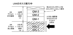
スタック領域122において、例えば、アドレスが大きくなる方向にデータが格納される。図2及び図3においては、上方向がアドレスの値が大きくなる方向である。そして、スタック領域122においては、アドレスが小さい方からASIL用スタック領域126、QM用スタック領域124の順で、メモリ領域が割り付けられている。すなわち、スタック領域122は、データが格納される方向側に、より重要度が低いスタック領域が設けられている。換言すると、各スタック領域122は、分割されたスタック領域のうち重要度が高いスタック領域からスタックデータが格納される方向に割り付けられている。
スタック領域122において、例えば、アドレスが大きくなる方向にデータが格納される。図2及び図3においては、上方向がアドレスの値が大きくなる方向である。そして、スタック領域122においては、アドレスが小さい方からASIL用スタック領域126、QM用スタック領域124の順で、メモリ領域が割り付けられている。すなわち、スタック領域122は、データが格納される方向側に、より重要度が低いスタック領域が設けられている。換言すると、各スタック領域122は、分割されたスタック領域のうち重要度が高いスタック領域からスタックデータが格納される方向に割り付けられている。
また、図2に記載のように、このスタック領域122において、ASIL用スタック領域126の最も新しく格納されたデータASIL-2を示す第1のスタックポインタと、QM用スタック領域124の最も新しく格納されたデータQM-3を示す第2のスタックポインタと、をモードに応じて切り換えることができる。図2は、SVMのタスクが実行されている場合を表している。この場合には、電子制御装置100は、第1のスタックポインタ及び第2のスタックポインタを任意に切り換えて使用することができる。そして、SVMのタスクが実行されるときには、QM用スタック領域124及びASIL用スタック領域126にアクセスすることが可能である。また、図3は、UMのタスクが実行されている場合を表している。この場合には、電子制御装置100は、第2のスタックポインタのみを使用する。そして、UMのタスクが実行されるときには、ASIL用スタック領域126へのアクセスが禁止されている。
このようにして、電子制御装置100において、CPU110がタスクを実行するときに、当該タスクに使用させるスタック領域として、ローカルメモリ120に確保された複数のスタック領域のうち少なくとも1つのスタック領域が選定される。そして、タスクが使用する少なくとも1つのスタック領域は、安全性レベルなどの所定規則によりタスクを分類したグループごとに設定されている。これにより、電子制御装置100における機能安全が実現される。
また、このように構成された電子制御装置100で実行されるタスクにおいては、割り当てられたモードよりも権限が高くなる方向にモード変更ができないようになっている。例えば、UMのタスクは、UMからSVMへのモード変更は行えない。
ここで、前記電子制御装置100がタスクを実行する際のフローについて図4を参照して説明する。
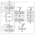
まず、このフローはモードがSVMで起動される。このとき、電子制御装置100は、フローがSVMで始まるので、ASIL用スタック領域126の最も新しく格納されたデータを示す第1のスタックポインタを使用している。そして、電子制御装置100は、イニシャルプログラムを実行する(S101)。
まず、このフローはモードがSVMで起動される。このとき、電子制御装置100は、フローがSVMで始まるので、ASIL用スタック領域126の最も新しく格納されたデータを示す第1のスタックポインタを使用している。そして、電子制御装置100は、イニシャルプログラムを実行する(S101)。
次に、プログラムの実行に際して、電子制御装置100は、UMのタスクを実行することがあり、それに伴いモードをSVMからUMに切り換える。このとき、まず、電子制御装置100は、スタックポインタをQM用スタック領域124の最も新しく格納されたデータを示す第2のスタックポインタに切り替える(S102)。そして、電子制御装置100は、モードをSVMからUMに切り換える(S103)。
そして、モードがUMに遷移した後に、電子制御装置100は、UMのタスクを実行して、その際にスタック領域としてQM用スタック領域124を使用する(S104)。
そして、モードがUMに遷移した後に、電子制御装置100は、UMのタスクを実行して、その際にスタック領域としてQM用スタック領域124を使用する(S104)。
例えば、UMのタスクとしては、アクセル開度から目標トルクを演算し、その目標トルクに基づいて電子制御スロットルの目標スロットル開度を演算する、目標トルク演算タスクがある。以下、目標トルク演算タスクが実行される例について説明する。
この目標トルク演算タスクにおいて、電子制御装置100は、まず、アクセルペダルセンサからアクセル開度の出力を読み込む。また、電子制御装置100は、アクセル開度から目標トルクを演算する。そして、電子制御装置100は、演算した目標トルクとなるように目標スロットル開度を演算し、その目標スロットル開度に基づいて電子制御スロットルを制御する。
次に、このような電子制御スロットルの制御において、異常が発生しているかを検知する必要がある。そこで、電子制御装置100は、目標トルクとは別に、現在のトルクを算出して、目標トルクと現在のトルクとを対比させて、異常が発生しているかを判定する。ここで、このような判定を行うタスクは、安全性のレベルがQMよりも高い(例えば、ASIL-C)。それゆえ、このタスクは、UMでは実行できず、SVMで実行する必要がある。そこで、電子制御装置100は、割り込み指令を出して、SVMの異常検知タスク(割り込み処理1)を割り込みさせることによって、異常が発生しているかを判定する。
割り込み処理1では、まず、電子制御装置100は、この異常検知タスクはSVMで実行されるため、ASIL用スタック領域126のデータを示す第1のスタックポインタを使用する必要がある。本実施形態では、割り込み前にはUMのタスクが実行されており、第2のスタックポインタが使用されているので、電子制御装置100は、スタックポインタを第1のスタックポインタに切り換えて、スタック領域としてASIL用スタック領域126を使用できるようにする(S201)。次に、電子制御装置100は、各種センサからの出力に基づいて現在のトルクを算出する。そして、電子制御装置100は、目標トルクと現在のトルクとを対比し、異常が発生しているか否かを判定する(S202)。
更に、前記異常の判定とは別に、電子制御装置100は、タスクの実行順や実行タイミングに異常があるか否かを判定し、その処置を行うタスクを実行する。このタスクは、安全性レベルがQMよりも高い(例えば、ASIL-C)。それゆえ、このタスクはSVMで実行する必要がある。そこで、割り込み処理1のステップ202での処理中に、このような機能動作の異常判定を行う必要がある場合には、電子制御装置100は、更に機能動作の異常判定タスクである割り込み処理2を実行する。この機能動作の異常判定タスクは、SVMで実行されるため、電子制御装置100は、まず、第1のスタックポインタが使用されているかを判定する。本実施形態では、割り込み処理1中に機能動作の異常判定が行われているので、既に第1のスタックポインタが使用され、スタック領域としてASIL用スタック領域126が使用可能となっている。したがって、電子制御装置100は、スタックポインタを切り換えない(S301)。そして、電子制御装置100は、前記機能動作の異常判定タスクを実行する(S302)。機能動作の異常判定タスクの終了後に戻る処理がSVMでの処理であるので、電子制御装置100は、スタックポインタを第1のスタックポインタから切り換えずに割り込み処理1に戻る(S303)。
電子制御装置100は、割り込み処理1を再開する。そして、電子制御装置100は、割り込み処理1が終了したら、戻るタスクがUMのタスクであるので、スタックポインタを第2のスタックポインタに切り換え、スタック領域としてQM用スタック領域124のみを使用するようにする(S203)。その後、電子制御装置100は、目標トルク演算タスクを再開する。
ここで、電子制御装置100における制御において、プログラムの書き換え等の特殊モードへのモード遷移が必要となる場合があり、UMからより高い重要度が割り当てられたSVMへ遷移することがある。しかし、電子制御装置100において、UMのタスクはQMからSVMにモード遷移することができない。ここで、本実施形態においては、低い重要度のモードから高い重要度のモードへの遷移は、SVMのタスクを割り込ませる割り込み処理にて実現する。具体的には、電子制御装置100は、割り込み命令を出し(S105)、これによりSVMのタスクを割り込ませて、UMからSVMにモード遷移をする(S401)。そして、モード遷移後に、SVMのタスクがスタックポインタを第1のスタックポインタに切り換えて、スタック領域としてASIL用スタック領域126を使用して処理するようにし(S106)、電子制御装置100は、特殊モードでの処理等を実行する。
以上のようにして、電子制御装置100は、複数のスタック領域が確保された上で、実行されるタスクに応じて割り込み処理を行い、適宜スタックポインタ及びスタック領域を切り換えてプログラムを実行する。
ここで、電子制御装置100は、複数のスタック領域が確保された場合において、タスクが実行される際に、そのタスクが属するグループに応じてスタック領域が適切に使用されているかを監視することができる。
このような監視をするタスクは、割り込み処理にて実行される。この割り込み処理について、図5及び6を参照しつつ説明する。
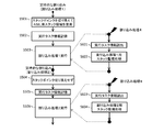
図5は、割り込み処理1及び割り込み処理2が実行されるフローにおいて、更に割り込み処理として、スタック領域の使用が適切に行われているかを監視するタスク(割り込み処理4)が実行される場合の概念図である。なお、上記説明した割り込み処理1及び2は定時的な割り込みとして実行される処理である。
このような監視をするタスクは、割り込み処理にて実行される。この割り込み処理について、図5及び6を参照しつつ説明する。
図5は、割り込み処理1及び割り込み処理2が実行されるフローにおいて、更に割り込み処理として、スタック領域の使用が適切に行われているかを監視するタスク(割り込み処理4)が実行される場合の概念図である。なお、上記説明した割り込み処理1及び2は定時的な割り込みとして実行される処理である。
図5において示されたフローは、定時的な割り込みである前記割り込み処理1が開始された状態から始まっている。そして、電子制御装置100は、割り込み処理1が実行されるので、スタックポインタを第1のスタックポインタに切り換えて、スタック領域としてASIL用スタック領域126を使用して処理する(S501)。そして、電子制御装置100は、タスクを実行する前に、実行するタスクを示す実行タスク情報を適切なメモリに記録する(S502)。その後、電子制御装置100は、割り込み処理1を実行する(S503)。
ここで割り込み処理1の実行中に、定時的な割り込みが実行されるタイミングとは相関しないタイミングで、実行中のタスクが、当該タスクが属するグループに応じて予め割り当てられたスタック領域を使用しているかを監視する、割り込み処理4が実行される。本実施形態においては、電子制御装置100は、クランク角センサ等のエンジン回転センサにおける立ち上がりエッジ及び立ち下りエッジの検出がなされるタイミングで、割り込み処理4を実行する。
この割り込み処理4では、電子制御装置100は、グループに属するタスクとそのグループのタスクに使用させる予め割り当てられたスタック領域とが関連付けられたテーブルを参照して、割り込み処理1で実行中のタスクが、そのタスクが属するグループに応じて予め割り当てられたスタック領域を使用しているか否かを監視する。
例えば、電子制御装置100は、まず、実行タスク情報を読み出す(S601)。そして、電子制御装置100は、グループに属するタスクと当該グループに応じて予め割り当てられたスタック領域のアドレスの範囲とがグループごとに関連付けられたテーブルを参照する。また、電子制御装置100は、実行タスク情報が属するグループに基づいて、そのグループに応じて予め割り当てられたスタック領域のアドレスの範囲をテーブルから読み出す。そして、電子制御装置100は、スタックポインタが、前記読み出した予め割り当てられたアドレスの範囲内を示していれば、実行タスクがその属するグループに応じて予め割り当てられたスタック領域を使用していると判定する。一方、電子制御装置100は、スタックポインタが、前記読み出した予め割り当てられたアドレスの範囲外を示していれば、実行タスクがその属するグループに応じて予め割り当てられたスタック領域を使用していないと判定する。そして、電子制御装置100は、実行タスクがその属するグループに応じて予め割り当てられたスタック領域を使用していると判定した場合には、割り込みを終了して元の処理に戻る。一方、電子制御装置100は、実行タスクがその属するグループに応じて予め割り当てられたスタック領域を使用していないと判定した場合には、例えば、外部装置にエラーを通知するか、又は、図示しない不揮発性のメモリ(フラッシュメモリ等)へエラーを記録する(S602)。
次に、スタック監視をする割り込み処理4が終了すると、電子制御装置100は、割り込み処理1に処理が戻す。そして、電子制御装置100は、前述したように、割り込み処理1の実行中に機能動作の異常判定タスクである割り込み処理2を定時的な割り込みとして実行する。割り込み処理2は、SVMのタスクであり、スタック領域は、ASIL用スタック領域126を使用する。既に、割り込み処理1において、第1のスタックポインタが使用されているので、電子制御装置100は、スタックポインタを切り換えない(S504)。そして、電子制御装置100は、S502と同様に、割り込み処理2の実行タスク情報を記録する(S505)。その後、電子制御装置100は、割り込み処理2を実行する。
ここで、割り込み処理2の実行中に、電子制御装置100は、例えば、エンジン回転センサにおけるエッジを検出して、スタック監視をする割り込み処理4を実行する。電子制御装置100は、この割り込み処理4で、実行タスク情報を読み出す(S603)。電子制御装置100は、読み出した実行タスク情報に基づいて、実行タスクがその属するグループに応じて予め割り当てられたスタック領域を使用しているかを判定し、S602と同様の処理を行う(S604)。その後、電子制御装置100は、割り込み処理4を終了させて、割り込み処理2の実行に戻る。
このようなタスク監視を行う一例において、時間、実行タスク、使用スタック領域、スタック監視タスクの実行タイミングの関係を、図6を参照して説明する。
まず、実行タスクと使用されるスタック領域との関係について説明する。時間t1で定時的な割り込みである割り込み処理1が実行される。この場合、使用されるスタック領域はASIL用スタック領域126である。次に、時間t2で割り込み処理2が実行される。この場合、使用されるスタック領域は、割り込み処理1と同様に、ASIL用スタック領域126である。そして、時間t3で割り込み処理2が終了し、割り込み処理1に戻る。更に、時間t4で割り込み処理1が終了し、通常タスクに戻る。このときに、スタックポインタが切り換わり、QM用スタック領域124を示すようになる。そして次に、時間t5で通常タスク実行中に定時割り込みで割り込み処理1が実行される。これに対しスタック監視タスクは、エンジン回転センサにおけるエッジの検出時(t11~t16)に割り込みを発生して、スタック監視タスクを実行する。ここで、エンジン回転センサにおけるエッジの検出タイミングは、定時的な割り込みである割り込み処理1及び割り込み処理2の割り込みのタイミングとは相関していない。このように、定時的な割り込みタイミングとは相関しない、エンジン回転センサにおけるエッジの検出タイミングで、スタック監視タスクを実行することにより、定時的ではないランダムなタイミングでスタック領域の使用を監視することができる。
まず、実行タスクと使用されるスタック領域との関係について説明する。時間t1で定時的な割り込みである割り込み処理1が実行される。この場合、使用されるスタック領域はASIL用スタック領域126である。次に、時間t2で割り込み処理2が実行される。この場合、使用されるスタック領域は、割り込み処理1と同様に、ASIL用スタック領域126である。そして、時間t3で割り込み処理2が終了し、割り込み処理1に戻る。更に、時間t4で割り込み処理1が終了し、通常タスクに戻る。このときに、スタックポインタが切り換わり、QM用スタック領域124を示すようになる。そして次に、時間t5で通常タスク実行中に定時割り込みで割り込み処理1が実行される。これに対しスタック監視タスクは、エンジン回転センサにおけるエッジの検出時(t11~t16)に割り込みを発生して、スタック監視タスクを実行する。ここで、エンジン回転センサにおけるエッジの検出タイミングは、定時的な割り込みである割り込み処理1及び割り込み処理2の割り込みのタイミングとは相関していない。このように、定時的な割り込みタイミングとは相関しない、エンジン回転センサにおけるエッジの検出タイミングで、スタック監視タスクを実行することにより、定時的ではないランダムなタイミングでスタック領域の使用を監視することができる。
なお、本明細書においては2つのCPU110で構成されたデュアルプロセッサについて説明したが、ローカルメモリ120をそれぞれ有する3以上のCPU110で構成されたマルチプロセッサにおいても、本実施形態に記載したスタック領域を適用することができる。また、マルチコアプロセッサにおいてコアごとにローカルメモリが接続されている場合に、その各ローカルメモリに本実施形態に記載したスタック領域を設けることができる。
本実施形態においては、2つの重要度に分けて2つのモードで実行される場合について説明したが、電子制御装置100は、3つ以上の重要度の分類が設けられて、その重要度の分類の数に応じてモードが分けられると共にスタック領域が複数確保されてもよい。
本明細書における、定時的とは、決められた時間間隔にという意味を指すだけではなく、決められた手順の中で決められたタイミングでという意味をも含む。
100…電子制御装置、120…ローカルメモリ、122…スタック領域
Claims (15)
- メモリ及びプロセッサを備えた電子制御装置において、
前記プロセッサが、タスクを実行するときに、当該タスクについて、前記メモリに確保された複数のスタック領域のうち、前記タスクに予め割り当てられた少なくとも1つの前記スタック領域を使用するように構成された、
ことを特徴とする電子制御装置。 - 前記タスクが使用する少なくとも1つのスタック領域は、所定規則によりタスクを分類したグループごとに設定された、
ことを特徴とする請求項1に記載の電子制御装置。 - 前記プロセッサはマルチコアプロセッサであって、コアごとに前記メモリが接続されている、
ことを特徴とする請求項1に記載の電子制御装置。 - 前記プロセッサが、前記メモリにおける各スタック領域のアドレスを示すポインタを切換えることで、前記タスクに予め割り当てられた少なくとも1つの前記スタック領域を使用するように構成された、
ことを特徴とする請求項1に記載の電子制御装置。 - 前記タスクは、安全性に応じて複数のレベルが設定されており、
前記プロセッサが、前記タスクのレベルに応じて少なくとも1つの前記スタック領域を選定するように構成された、
ことを特徴とする請求項1に記載の電子制御装置。 - 前記プロセッサが、前記タスクを実行するとき、当該タスクよりレベルが高いタスクに予め割り当てられた少なくとも1つの前記スタック領域の使用を禁止するように構成された、
ことを特徴とする請求項5に記載の電子制御装置。 - 前記プロセッサが、実行中のタスクよりレベルが高いタスクを実行する場合、当該タスクを実行させるための割込み処理を発生させるように構成された、
ことを特徴とする請求項5に記載の電子制御装置。 - 前記スタック領域は、車両の安全機能に関するレベルごとに分けられている、
ことを特徴とする請求項1に記載の電子制御装置。 - 電子制御装置が、タスクを実行するときに、当該タスクについて、メモリに確保された複数のスタック領域のうち、前記タスクに予め割り当てられた少なくとも1つの前記スタック領域を使用する、
ことを特徴とするスタック使用方法。 - 前記タスクが使用する少なくとも1つのスタック領域は、所定規則によりタスクを分類したグループごとに設定された、
ことを特徴とする請求項9に記載のスタック使用方法。 - 前記プロセッサが、前記メモリにおける各スタック領域のアドレスを示すポインタを切換えることで、前記タスクに予め割り当てられた少なくとも1つの前記スタック領域を使用する、
ことを特徴とする請求項9に記載のスタック使用方法。 - 前記タスクは、安全性に応じて複数のレベルが設定されており、
前記プロセッサが、前記タスクのレベルに応じて少なくとも1つの前記スタック領域を選定する、
ことを特徴とする請求項9に記載のスタック使用方法。 - 前記プロセッサが、前記タスクを実行するとき、当該タスクよりレベルが高いタスクに予め割り当てられた少なくとも1つの前記スタック領域の使用を禁止する、
ことを特徴とする請求項12に記載のスタック使用方法。 - 前記プロセッサが、実行中のタスクよりレベルが高いタスクを実行する場合、当該タスクを実行させるための割込み処理を発生させる、
ことを特徴とする請求項12に記載のスタック使用方法。 - 前記スタック領域は、車両の安全機能に関するレベルごとに分けられている、
ことを特徴とする請求項9に記載のスタック使用方法。
Priority Applications (3)
| Application Number | Priority Date | Filing Date | Title |
|---|---|---|---|
| DE112016003029.0T DE112016003029T5 (de) | 2015-07-01 | 2016-06-30 | Elektronische steuervorrichtung und stapelverwendungsverfahren |
| US15/738,319 US20180173559A1 (en) | 2015-07-01 | 2016-06-30 | Electronic Control Device and Stack Usage Method |
| CN201680036746.5A CN107710162B (zh) | 2015-07-01 | 2016-06-30 | 电子控制装置及栈使用方法 |
Applications Claiming Priority (2)
| Application Number | Priority Date | Filing Date | Title |
|---|---|---|---|
| JP2015-132780 | 2015-07-01 | ||
| JP2015132780A JP6771272B2 (ja) | 2015-07-01 | 2015-07-01 | 車載電子制御装置及びスタック使用方法 |
Publications (1)
| Publication Number | Publication Date |
|---|---|
| WO2017002939A1 true WO2017002939A1 (ja) | 2017-01-05 |
Family
ID=57608334
Family Applications (1)
| Application Number | Title | Priority Date | Filing Date |
|---|---|---|---|
| PCT/JP2016/069511 Ceased WO2017002939A1 (ja) | 2015-07-01 | 2016-06-30 | 電子制御装置及びスタック使用方法 |
Country Status (5)
| Country | Link |
|---|---|
| US (1) | US20180173559A1 (ja) |
| JP (1) | JP6771272B2 (ja) |
| CN (1) | CN107710162B (ja) |
| DE (1) | DE112016003029T5 (ja) |
| WO (1) | WO2017002939A1 (ja) |
Families Citing this family (1)
| Publication number | Priority date | Publication date | Assignee | Title |
|---|---|---|---|---|
| JP7449219B2 (ja) | 2020-12-03 | 2024-03-13 | 日立Astemo株式会社 | 内燃機関の制御装置 |
Citations (4)
| Publication number | Priority date | Publication date | Assignee | Title |
|---|---|---|---|---|
| JPH09505922A (ja) * | 1994-09-19 | 1997-06-10 | フィリップス エレクトロニクス ネムローゼ フェンノートシャップ | 多数のマイクロ制御器の演算を実行するマイクロ制御器システム |
| JP2011070290A (ja) * | 2009-09-24 | 2011-04-07 | Renesas Electronics Corp | データプロセッサ |
| JP2014049013A (ja) * | 2012-09-03 | 2014-03-17 | Hitachi Automotive Systems Ltd | 自動車用電子制御システム |
| JP2014074995A (ja) * | 2012-10-03 | 2014-04-24 | Toyota Motor Corp | 情報処理装置 |
Family Cites Families (26)
| Publication number | Priority date | Publication date | Assignee | Title |
|---|---|---|---|---|
| US3828742A (en) * | 1972-04-26 | 1974-08-13 | Caterpillar Tractor Co | Engine control system |
| US4600867A (en) * | 1983-11-01 | 1986-07-15 | Nippon Soken, Inc. | Motor speed controlling device |
| JPH0697003B2 (ja) * | 1984-12-19 | 1994-11-30 | 日本電装株式会社 | 内燃機関の運転状態制御装置 |
| JP3442807B2 (ja) * | 1993-01-21 | 2003-09-02 | 富士重工業株式会社 | エンジン回転のシミュレーション方法 |
| US6490509B1 (en) * | 1999-09-17 | 2002-12-03 | Keihin Corporation | Car controlling unit using a multitasking system |
| JP2003167737A (ja) * | 2001-11-30 | 2003-06-13 | Nec Corp | スタック使用方法 |
| GB2392515B (en) * | 2002-08-28 | 2005-08-17 | Livedevices Ltd | Improvements relating to stack usage in computer-related operating systems |
| JP4487588B2 (ja) * | 2004-02-18 | 2010-06-23 | アイシン精機株式会社 | 開閉体制御装置 |
| JP4241462B2 (ja) * | 2004-03-26 | 2009-03-18 | 株式会社デンソー | 制御ユニットおよびマイクロコンピュータ |
| JP2005351042A (ja) * | 2004-06-14 | 2005-12-22 | Aisin Seiki Co Ltd | 開閉体制御装置 |
| US9037152B1 (en) * | 2005-11-12 | 2015-05-19 | Alberto Herrera | Small footprint real-time operating system for reactive systems |
| JP2007257257A (ja) * | 2006-03-23 | 2007-10-04 | Matsushita Electric Ind Co Ltd | マルチタスクシステムにおけるタスク実行環境切替え方法 |
| JP4770602B2 (ja) * | 2006-06-23 | 2011-09-14 | 株式会社デンソー | 電子機器 |
| US8516462B2 (en) * | 2006-10-09 | 2013-08-20 | International Business Machines Corporation | Method and apparatus for managing a stack |
| KR101334172B1 (ko) * | 2007-01-05 | 2013-11-28 | 삼성전자주식회사 | 임베디드 시스템의 스택 오버플로우 방지 방법 및 장치 |
| KR101352512B1 (ko) * | 2007-01-15 | 2014-01-17 | 삼성전자주식회사 | 효율적인 메모리 사용을 위한 스택 관리 장치 및 방법 |
| JP5044387B2 (ja) * | 2007-12-26 | 2012-10-10 | ルネサスエレクトロニクス株式会社 | 情報処理装置及びそのスタックポインタ更新方法 |
| WO2011055585A1 (ja) * | 2009-11-03 | 2011-05-12 | 新東工業株式会社 | 電動シリンダの制御方法及び電動シリンダの制御システム |
| JP2011176918A (ja) * | 2010-02-23 | 2011-09-08 | On Semiconductor Trading Ltd | モータ駆動回路 |
| JP2012093832A (ja) * | 2010-10-25 | 2012-05-17 | Toyota Motor Corp | 情報処理装置 |
| FR2977694A1 (fr) * | 2011-07-08 | 2013-01-11 | St Microelectronics Rousset | Microprocesseur protege contre un debordement de pile |
| US9389936B2 (en) * | 2011-09-23 | 2016-07-12 | Microsoft Technology Licensing, Llc. | Monitoring the responsiveness of a user interface |
| WO2014172369A2 (en) * | 2013-04-15 | 2014-10-23 | Flextronics Ap, Llc | Intelligent vehicle for assisting vehicle occupants and incorporating vehicle crate for blade processors |
| KR101470162B1 (ko) * | 2013-05-30 | 2014-12-05 | 현대자동차주식회사 | 메모리 스택 사이즈 모니터링 방법 |
| US9529625B2 (en) * | 2014-04-01 | 2016-12-27 | Samsung Electronics Co., Ltd | Method and system for providing stack memory management in real-time operating systems |
| JP6300371B2 (ja) * | 2014-11-20 | 2018-03-28 | ミネベアミツミ株式会社 | モータ駆動制御装置およびモータ駆動制御方法 |
-
2015
- 2015-07-01 JP JP2015132780A patent/JP6771272B2/ja active Active
-
2016
- 2016-06-30 WO PCT/JP2016/069511 patent/WO2017002939A1/ja not_active Ceased
- 2016-06-30 DE DE112016003029.0T patent/DE112016003029T5/de active Pending
- 2016-06-30 CN CN201680036746.5A patent/CN107710162B/zh active Active
- 2016-06-30 US US15/738,319 patent/US20180173559A1/en not_active Abandoned
Patent Citations (4)
| Publication number | Priority date | Publication date | Assignee | Title |
|---|---|---|---|---|
| JPH09505922A (ja) * | 1994-09-19 | 1997-06-10 | フィリップス エレクトロニクス ネムローゼ フェンノートシャップ | 多数のマイクロ制御器の演算を実行するマイクロ制御器システム |
| JP2011070290A (ja) * | 2009-09-24 | 2011-04-07 | Renesas Electronics Corp | データプロセッサ |
| JP2014049013A (ja) * | 2012-09-03 | 2014-03-17 | Hitachi Automotive Systems Ltd | 自動車用電子制御システム |
| JP2014074995A (ja) * | 2012-10-03 | 2014-04-24 | Toyota Motor Corp | 情報処理装置 |
Also Published As
| Publication number | Publication date |
|---|---|
| CN107710162A (zh) | 2018-02-16 |
| DE112016003029T5 (de) | 2018-03-22 |
| JP6771272B2 (ja) | 2020-10-21 |
| CN107710162B (zh) | 2022-06-03 |
| US20180173559A1 (en) | 2018-06-21 |
| JP2017016409A (ja) | 2017-01-19 |
Similar Documents
| Publication | Publication Date | Title |
|---|---|---|
| JP5867495B2 (ja) | 電子制御装置 | |
| JP5316718B1 (ja) | マルチコア・プロセッサ | |
| JP5975923B2 (ja) | 車両用制御装置 | |
| JP3610915B2 (ja) | 処理実行装置及びプログラム | |
| JP5533789B2 (ja) | 車載電子制御装置 | |
| JP6466269B2 (ja) | 電子制御装置及びスタック領域の使用監視方法 | |
| JP2011153596A (ja) | 内燃機関制御装置 | |
| JP6306530B2 (ja) | 自動車用電子制御装置 | |
| US20180259577A1 (en) | Electronic control apparatus and method | |
| JP5978873B2 (ja) | 電子制御装置 | |
| JP5699896B2 (ja) | 情報処理装置、異常判定方法 | |
| JP6771272B2 (ja) | 車載電子制御装置及びスタック使用方法 | |
| JP6877475B2 (ja) | 電子制御装置及びスタック使用方法 | |
| JP6519515B2 (ja) | マイクロコンピュータ | |
| JP6471510B2 (ja) | マイクロコンピュータ | |
| JP2010113419A (ja) | マルチコア制御装置 | |
| JP6365387B2 (ja) | 電子制御装置 | |
| JP7226064B2 (ja) | 電子制御装置 | |
| US20070239916A1 (en) | Input-output control apparatus, input-output control method, process control apparatus and process control method | |
| JP5942904B2 (ja) | 処理装置 | |
| JP2021047513A (ja) | 電子制御装置 | |
| JP6394442B2 (ja) | 電子制御装置 | |
| JP2014035741A (ja) | 電子制御装置 | |
| JP2021076021A (ja) | 電子制御装置 | |
| JP6596455B2 (ja) | 自動車用電子制御装置 |
Legal Events
| Date | Code | Title | Description |
|---|---|---|---|
| 121 | Ep: the epo has been informed by wipo that ep was designated in this application |
Ref document number: 16818047 Country of ref document: EP Kind code of ref document: A1 |
|
| WWE | Wipo information: entry into national phase |
Ref document number: 15738319 Country of ref document: US |
|
| WWE | Wipo information: entry into national phase |
Ref document number: 112016003029 Country of ref document: DE |
|
| 122 | Ep: pct application non-entry in european phase |
Ref document number: 16818047 Country of ref document: EP Kind code of ref document: A1 |