WO2017002846A1 - 視機能測定装置、および視機能測定プログラム - Google Patents
視機能測定装置、および視機能測定プログラム Download PDFInfo
- Publication number
- WO2017002846A1 WO2017002846A1 PCT/JP2016/069253 JP2016069253W WO2017002846A1 WO 2017002846 A1 WO2017002846 A1 WO 2017002846A1 JP 2016069253 W JP2016069253 W JP 2016069253W WO 2017002846 A1 WO2017002846 A1 WO 2017002846A1
- Authority
- WO
- WIPO (PCT)
- Prior art keywords
- eye
- examined
- correction
- visual function
- measurement
- Prior art date
- Legal status (The legal status is an assumption and is not a legal conclusion. Google has not performed a legal analysis and makes no representation as to the accuracy of the status listed.)
- Ceased
Links
Images





Classifications
-
- A—HUMAN NECESSITIES
- A61—MEDICAL OR VETERINARY SCIENCE; HYGIENE
- A61B—DIAGNOSIS; SURGERY; IDENTIFICATION
- A61B3/00—Apparatus for testing the eyes; Instruments for examining the eyes
- A61B3/10—Objective types, i.e. instruments for examining the eyes independent of the patients' perceptions or reactions
-
- A—HUMAN NECESSITIES
- A61—MEDICAL OR VETERINARY SCIENCE; HYGIENE
- A61B—DIAGNOSIS; SURGERY; IDENTIFICATION
- A61B3/00—Apparatus for testing the eyes; Instruments for examining the eyes
- A61B3/10—Objective types, i.e. instruments for examining the eyes independent of the patients' perceptions or reactions
- A61B3/103—Objective types, i.e. instruments for examining the eyes independent of the patients' perceptions or reactions for determining refraction, e.g. refractometers, skiascopes
Definitions
- the present disclosure relates to a visual function measuring device and a visual function measuring program for measuring the visual function of an eye to be examined.
- an ophthalmic apparatus that objectively measures eye refractive power is generally used, and a subjective value test is performed based on the objective refractive power value obtained thereby, and the prescription frequency for long-term use Is determined.
- Non-Patent Document 1 a fixation target (stimulus target) is set every 0.5D steps from a distance.
- the time-dependent change of the refractive power data when the fixation target is stopped at each of the eight positions is sampled for 20 seconds, and a predetermined high-frequency component of the time-dependent change of the sampled refractive power data is sampled.
- the appearance frequency By determining the appearance frequency, the accommodation function of the eye to be examined is objectively measured.
- the present disclosure is characterized by having the following configuration.
- a visual function measuring device that measures the visual function of a subject's eye, and projects measurement light onto the fundus of the subject's eye and measures the eye refractive power of the subject's eye based on the reflected light from the fundus
- the fixation target presenting optical system capable of changing the position of the fixation target presented to the eye to be examined with respect to the eye to be examined, and the correction optical system, and determining the eye refractive power of the eye to be examined
- a visual function measuring device for measuring a visual function of a subject's eye, which projects measurement light onto the fundus of the subject's eye and measures the eye refractive power of the subject's eye based on the reflected light from the fundus Driving the measurement optical system, the fixation target presenting optical system capable of changing the position of the fixation target presented to the eye to be examined with respect to the eye to be examined, and the correction optical system, and determining the eye refractive power of the eye to be examined Correction means for correcting, and control means for calculating an adjustment tension parameter of the eye to be examined from a change with time of the eye refractive power measured by the measurement optical system, the control means being operated by the subject.
- a working distance when performing is acquired, and a correction value based on the acquired working distance is output.
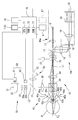
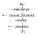
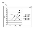
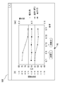
- FIG. 1 is an external view of a visual function measuring device according to an embodiment. It is a schematic block diagram of an optical system and a control part. It is a figure which shows an example of the measurement screen displayed on a display part. It is a flowchart which shows the control action of a present Example. It is a figure which shows an example of the screen at the time of comparing and displaying the adjustment tension parameter measured in a different correction value. It is a figure which shows an example of the screen at the time of displaying the difference of the adjustment tension parameter measured in a different correction value. It is a figure which shows an example of the screen at the time of displaying the adjustment tension parameter measured in the some correction value. It is a figure which shows an example of the time-dependent change of an adjustment tension parameter. It is a figure which shows an example of the screen which displays the correction value of spectacles according to work distance.
- the visual function measuring device measures, for example, the visual function of the eye to be examined.
- the visual function may be, for example, an adjustment tension parameter.
- the accommodation tension parameter may be, for example, the appearance frequency of the accommodation fine movement high frequency component.
- the appearance frequency of the adjustment fine movement high frequency component may be calculated based on, for example, a change in refractive power measured in a state where the fixation target is stopped for a predetermined time at a plurality of positions.
- the visual function measuring device includes, for example, a measurement optical system (for example, measurement optical system 10), a fixation target presenting optical system (for example, fixation target presenting optical system 30), and a correction unit (for example, correction unit 60). And a control unit (for example, the control unit 70).
- the measurement optical system may project measurement light onto the fundus of the subject's eye and measure the eye refractive power of the subject's eye based on the reflected light from the fundus.
- the fixation target presenting optical system presents a fixation target to the eye to be examined.
- the fixation target presenting optical system may include, for example, a fixation target that can change the presentation position.
- the correction unit may correct the refractive power of the eye to be examined.
- the correction unit may include a drive unit.
- the correction unit drives a correction optical system (for example, the visible light source 31, the fixation target plate 32, the projection lens 33, the cylindrical lenses 38a and 38b) that can correct the eye refractive power of the eye to be examined by the driving unit.
- a correction optical system for example, the visible light source 31, the fixation target plate 32, the projection lens 33, the cylindrical lenses 38a and 38b
- the eye refractive power of the eye to be examined may be corrected.
- the control unit may calculate, for example, an accommodation tension parameter of the eye to be examined from a temporal change in eye refractive power measured by the measurement optical system.
- the control unit may acquire the frequency information of the glasses worn by the subject.
- the control unit may control the correction unit based on the frequency information and change the correction state (correction condition) of the eye to be examined.
- a control part may measure the accommodation tension parameter of a to-be-tested eye in the correction state based on frequency information.
- the frequency information of the glasses may be acquired from, for example, a lens meter (for example, the lens meter LM), or may be acquired by operating an operation unit (for example, the operation unit 8) by an examiner.
- the frequency information of the glasses may be, for example, the frequency information of the glasses currently worn by the subject, the frequency information of the glasses to be newly prescribed to the subject, The frequency information of the glasses worn by the person in the past may be used.
- control unit may control the correction unit based on the frequency information of the glasses, and measure the adjustment tension parameter in the same correction state as when the glasses are worn. This makes it possible to measure the adjustment tension parameter in an environment close to that when glasses are actually worn.
- control unit may present the fixation target from a distance and calculate the adjustment tension parameter in the correction state of the correction optical system set based on the power information of the glasses. Further, the control unit may present a fixation target from a near distance and calculate an adjustment tension parameter in a correction state of the correction optical system set based on the power information of the glasses. Further, the control unit may present the fixation target at different presentation distances in the correction state of the correction optical system set based on the power information of the glasses, and calculate the adjustment tension parameter. Different presentation distances can include, for example, a long distance, a medium distance, a short distance, and the like.
- control unit may obtain the temporal change in eye refractive power at each presentation position changed by the fixation target presenting optical system.
- the control unit may acquire eye point information.
- the eye point may be, for example, an intersection between the line of sight of the eye to be examined and the lens surface of the spectacle lens.
- the control unit may acquire eye point information when the eye to be examined fixes the fixation target presented at each presentation position.
- a control part may acquire the correction power according to the eye point in each presentation position based on the eye point and the power information of a spectacle lens.
- the control unit may control the correction unit so that the eye refractive power is corrected with the correction power corresponding to the eye point.
- the control unit may switch the presenting position of the fixation target and switch the correction power of the correction unit. Accordingly, the control unit can measure the adjustment tension parameter with the correction power corresponding to each presentation position of the fixation target.
- control unit may acquire, for example, power information of the progressive lens.
- control unit may acquire the distance power and the near power of the progressive lens.
- control unit may switch the correction power from the distance power to the near power by controlling the correction unit when the presenting position of the fixation target is switched from far to near.
- the control unit can measure the adjustment tension parameter in an environment close to the case where the subject wears progressive glasses.
- the control unit may correct the eye to be examined in a plurality of different correction states (correction conditions) by controlling the correction unit.
- the control unit may measure the adjustment tension parameter of the eye to be examined in a plurality of different correction states.
- the control unit may cause the display unit to display the measured adjustment tension parameter of the eye to be examined in a plurality of correction states.
- the control unit may display the measured adjustment tension parameters in a plurality of correction states side by side on the display unit.
- the examiner can easily confirm the correction state suitable for the eye to be examined.
- control unit may display, for example, a plurality of adjustment tension parameters acquired for each of a plurality of measurements in the same subject on the display unit over time.
- control unit may store the measurement results measured on different days or different times in the storage unit (for example, the storage unit 74). Then, the control unit may cause the display unit to display the measurement results of different days stored in the storage unit over time. This makes it easy to confirm the effects of prescription glasses.
- the control unit may acquire event information related to the subject.
- the control unit may acquire event information based on an input to the operation unit, or may acquire event information from an external device that is connected to be communicable.
- the event information may be, for example, prescription date for eyeglasses, treatment date for eye drops, frequency of prescription eyeglasses, total number of eye drops, amount of eye drops, and the like.
- the control unit may display the event information together with the display of the measurement result as described above. Thus, the examiner can easily confirm the effect of the prescription glasses.
- the visual function measuring device of the present embodiment may further include a photographing unit (for example, the observation optical system 50).
- the imaging unit may image, for example, the anterior segment of the eye to be examined.
- the control unit may acquire the pupil diameter of the eye to be examined by performing image processing on the anterior segment image captured by the imaging unit. Further, the control unit may display the pupil diameter together with the time display of the measurement result as described above.
- the examiner can easily confirm the temporal change of the pupil diameter due to, for example, eye drops.
- the visual function measuring device of the present embodiment may include a storage unit (for example, the storage unit 74).
- the storage unit may store a comparison parameter.
- the parameter for comparison may be a parameter for comparison with the accommodation tension parameter obtained by measuring the eye to be examined.
- the comparison parameter may be created based on, for example, a plurality of adjustment tension parameters obtained by measuring a plurality of subjects.
- the comparison parameter may be an average value of a plurality of adjustment tension parameters.
- the comparison parameter may be created based on the adjustment tension parameter of one subject, or may be a value acquired by the examiner inputting with the operation unit or the like. The examiner can easily grasp the abnormality of the eye to be examined by comparing the adjustment parameter and the comparison parameter.
- control unit may calculate a difference between the accommodation tension parameter obtained by measuring the eye to be examined and the comparison parameter stored in the storage unit as an evaluation value. For example, the control unit may output the calculated difference to the display unit.
- control unit may acquire the work distance.
- the work distance is, for example, the distance to the position where the subject gazes when performing work.
- the control unit may acquire a work distance based on an operation signal from the operation unit, or may acquire a work distance from an external device that is communicably connected.
- the control unit may output a correction value based on the acquired work distance.
- the control unit may cause the display unit or the like to display a prescription value of glasses suitable for the acquired work distance.
- the control unit may output the refraction value of the eye to be examined measured by the measurement optical system at the fixation target presentation position corresponding to the acquired working distance.
- the examiner can easily confirm the prescription value of the glasses suitable for the work distance of the subject.
- the visual function measurement device of the present embodiment may further include, for example, a line-of-sight change unit (for example, a line-of-sight change unit 65).
- the line-of-sight changing unit may change the line-of-sight direction of the subject, for example.
- the line-of-sight changing unit may change the direction of the subject's line of sight, for example, by changing the direction of the subject's face, or by moving the fixation target with respect to the eye to be examined.
- the viewing direction may be changed.
- the line-of-sight changing unit may rotate a face support unit (for example, the face support unit 6) that supports the face of the eye to be examined.
- the line-of-sight changing unit may move the fixation target (for example, the visible light source 31, the fixation target plate 32, etc.) with respect to the eye to be examined,
- the apparatus main body may be moved relative to the eye to be examined.
- the control unit may acquire the gaze direction of the eye to be inspected when the fixation target presented at each presentation position is fixed. For example, the control unit may acquire the gaze direction of the subject's eye based on the detection result of the gaze detection device that detects the gaze direction, or may determine the gaze direction of the subject based on the measurement result of the eye point measurement device. You may get it.
- the control unit may receive the gaze direction of the subject from the gaze detection device or the eye point measurement device that is communicably connected, or may accept the gaze direction based on an operation signal from the operation unit.
- the control unit may control the line-of-sight changing unit based on the acquired line-of-sight direction to change the line-of-sight direction of the eye to be examined with respect to each presentation position of the fixation target. For example, the control unit may control the line-of-sight changing unit to switch the fixation target presentation position and switch the subject's line-of-sight direction to the line-of-sight direction corresponding to each presentation position.
- the adjustment tension parameter can be measured by the line of sight when the object or position is gazes at the implementation.
- the control unit can acquire the adjustment tension parameter in a state of convergence close to when the subject gazes with both eyes.
- the control unit may cause the visual function measurement device to execute the visual function measurement program stored in the storage unit.
- the visual function measurement program may be a program including an acquisition step, a correction step, a measurement step, and a calculation step.
- the acquisition step may be, for example, a step of acquiring spectacle information of spectacles worn by the subject.
- the correction step may be a step of correcting the eye refractive power of the eye to be examined based on spectacle information, for example.
- the measuring step is a step of projecting measurement light onto the fundus of the eye to be examined that has fixed the fixation target in the correction state in the correction step, for example, and measuring the eye refractive power of the eye to be examined based on the reflected light from the fundus It may be.
- the calculating step may be a step of calculating an accommodation tension parameter of the eye to be examined from a change in eye refractive power with time in the measuring step.
- FIG. 1 is an external configuration diagram of a measuring apparatus 1 according to an embodiment.
- the measuring device 1 is a device that measures the visual function of the eye E, for example.
- the measuring apparatus 1 may measure the accommodation tension parameter, eye refractive power, and the like of the eye to be examined.
- the adjustment tension parameter may be, for example, a parameter indicating the adjustment tension of the eye to be examined.
- the adjustment tension parameter is obtained by sampling a change in refractive power data with time when the fixation target is in a stopped state for a few seconds, and an appearance frequency (HFC) of a predetermined high-frequency component obtained with respect to the change with time in the sampled refractive power data. ).
- HFC appearance frequency
- the human eye is perceived to be in a stationary refractive state when it is staring at a stationary target, but when objective observation of refractive power is performed over time, A sine wave-like swing called fine adjustment is observed.
- the high-frequency component of the accommodation fine movement is caused by the vibration of the lens refractive power and indirectly indicates the ciliary muscle activity state.
- the degree of accommodation tension of the eye to be examined can be estimated by examining the appearance frequency (hereinafter also referred to as HFC) of the accommodation fine movement high frequency component.
- the measuring apparatus 1 mainly includes, for example, a base 2, a housing 3, a measuring unit 4, an XYZ driving unit 5, a face support unit 6, a display unit 7, an operation unit 8, a control unit 70, and the like.
- the measurement unit 4 houses a measurement optical system described later.
- the measurement unit 4 is moved in the left-right direction (X direction), the up-down direction (Y direction), and the front-rear direction (Z direction) with respect to the eye E by an XYZ drive unit 5 provided on the base 2.
- the XYZ drive unit 5 includes a slide mechanism, a motor, and the like provided for each of the X, Y, and Z directions.
- the face support 6 is attached to the base 2.
- the face support unit 6 supports, for example, the subject's face.
- the operation unit 8 is provided with buttons for performing various settings, for example.
- the display unit 7 displays various information such as an observation image of the eye E and a measurement result, for example.
- the display unit 7 may be, for example, a touch panel. In this case, the display unit 7 may also be used as the operation unit 8.
- the control unit 70 controls the entire apparatus. As illustrated in FIG. 2, the control unit 70 is realized by, for example, a general CPU (Central Processing Unit) 71, a ROM 72, a RAM 73, and the like. In the ROM 72, for example, various programs for controlling the operation of the measuring apparatus 1, initial values, and the like are stored. The RAM 73 temporarily stores various information, for example.
- the control unit 70 may be configured by a plurality of control units 70 (that is, a plurality of processors). The control unit 70 may control the entire apparatus and may calculate the refractive power of the eye E.
- the control unit 70 includes, for example, a storage unit (for example, a non-volatile memory) 74, a measurement unit 4, an XYZ drive unit 5, a display unit 7, an operation unit 8, drive units 23, 61, and 62 described later, and an image sensor described later. 22, 52, etc. are electrically connected (see FIG. 2).
- the connection method may be, for example, wired, wireless, or both.
- the storage unit 74 is, for example, a non-transitory storage medium that can retain stored contents even when power supply is interrupted. For example, a hard disk drive, a flash ROM, a removable USB memory, or the like can be used as the storage unit 74.
- an external computer PC may be connected to the control unit 70 so as to communicate with each other.
- the computer PC may perform visual function calculation, device control, data input / output, and the like.
- the lens meter LM is a device that obtains optical characteristics of a lens by, for example, projecting a measurement light beam onto a lens and receiving the measurement light beam transmitted through the lens with a light receiving element (see Japanese Patent Application Laid-Open No. 2006-189386). ).
- FIG. 2 is a schematic configuration diagram of an optical system and a control system of the apparatus.
- the measurement optical system 10 includes, for example, a projection optical system 10a and a light receiving optical system 10b.
- the projection optical system 10a projects a spot-shaped measurement index light beam onto the fundus oculi Ef of the eye E through the center of the pupil of the eye E.
- the light receiving optical system 10b extracts the measurement index light beam reflected from the fundus oculi Ef in a ring shape through the pupil periphery.
- the projection optical system 10a includes, for example, a measurement light source 11, a relay lens 12, a hall mirror 13, a prism 15, an objective lens 14, and the like.
- the measurement light source 11 may be, for example, an LED disposed on the optical axis L1 of the measurement optical system 10 or an SLD.
- the measurement light source 11 may be in a positional relationship optically conjugate with the fundus oculi Ef of the normal eye.
- the opening of the hall mirror 13 is optically conjugate with the pupil of the eye E.
- the prism 15 may be rotated about the optical axis L1 by the driving unit 23, for example.
- the light receiving optical system 10b for example, the objective lens, the prism 15, and the hall mirror 13 of the projection optical system 10a may be shared.
- the light receiving optical system 10b may include, for example, a relay lens 16, a total reflection mirror 17, a light receiving diaphragm 18, a collimator lens 19, a ring lens 20, and an image pickup element (for example, an area CCD) 22.
- the light receiving diaphragm 18 and the imaging element 22 may be in a positional relationship optically conjugate with the fundus oculi Ef.
- the ring lens 20 is composed of, for example, a lens portion in which a cylindrical lens is formed in a ring shape on one side of a transparent flat plate shape, and a light shielding portion by a light shielding coating other than the ring-shaped cylindrical lens portion of the lens portion. May be. Further, the ring lens 20 may have a positional relationship optically conjugate with the pupil of the eye E, for example.
- a beam splitter 29 is disposed between the objective lens 14 and the eye E to be examined.
- the beam splitter 29 guides the fixation target light flux from the fixation target presenting optical system 30 to the eye E to be examined and guides the reflected light from the anterior eye portion of the eye E to the observation optical system 50.
- the fixation target presenting optical system 30 is used as an example of a fixation target presenting unit that presents a fixation target to the eye to be examined.
- the fixation target presenting optical system 30 presents a fixation target to the eye to be examined, for example.
- the fixation target presenting optical system is disposed on the optical axis L2 that is coaxial with the optical axis L1 by the beam splitter 29.
- the fixation target presentation optical system 30 includes, for example, a visible light source 31, a fixation target plate 32, a light projection lens 33, a drive unit 34, a half mirror 35, an observation objective lens 36, cylindrical lenses 38a and 38b, and the like.
- the cylindrical lenses 38a and 38b are, for example, positive cylindrical lenses having the same focal length, and constitute an astigmatism correcting optical system.
- the cylindrical lenses 38a and 38b can be rotated independently of each other in the same direction or in the opposite direction around the optical axis, and an astigmatic (cylindrical) component can be created by relatively rotating the two.
- the correction unit 60 may correct the refractive power of the eye E to fixate the fixation target.
- the correction unit 60 mainly includes, for example, a drive unit 61, a drive unit 62, and the like.
- the control unit 70 controls the driving of the driving unit 61 and moves the visible light source 31 and the fixation target plate 32 in the direction of the optical axis L2, thereby changing the display position of the fixation target to be presented to the subject. To do.
- the correction unit 60 corrects the refractive power of the eye to be inspected when fixing to the fixation target.
- the correction unit 60 may correct the refractive power by inserting / removing an optical element such as a lens to / from the optical axis L2 of the fixation target presenting optical system, or the optical element may be moved along the optical axis L2. By doing so, the refractive power may be corrected.
- the control unit 70 may change the correction state of the refractive power by controlling the correction unit 60.
- control unit 70 controls, for example, driving of the driving unit 62 and rotates the cylindrical lenses 38a and 38b independently of each other. Accordingly, the control unit 70 may correct astigmatism of the eye to be examined when fixing the fixation target.
- the driving unit 61 of this embodiment may be a stepping motor.
- the controller 70 may detect the position of the fixed index plate 32 on the optical axis L2 by using, for example, a stepping motor and a photo interrupter.
- the parts constituting the drive unit 61 are not limited to the present embodiment. Any configuration may be used as long as the control unit 70 can control the movement of the fixed index 32 and detect the position on the optical axis L2.
- correction unit 60 of the present embodiment is driven by driving an optical element (for example, a fixation target presenting optical system) disposed on an optical axis L2 different from the measurement optical axis L1 of the measurement optical system 10, for example. Correct the refractive power of the optometry.
- an optical element for example, a fixation target presenting optical system
- the index projection optical system 45 is an optical system that projects an alignment index for detection in the front-rear direction (Z direction), and two sets of first projection optical systems 45a and 45b arranged symmetrically with the measurement optical axis L1 in between. Two sets of second projection optical systems 45c and 45d having an optical axis arranged at a narrower angle than the first projection optical systems 45a and 45b and arranged symmetrically across the measurement optical axis L1 are provided.
- the first projection optical systems 45a and 45b have point light sources 46a and 46b that emit near-infrared light, and collimator lenses 47a and 47b, and project an index at infinity onto the eye E to be examined by light of substantially parallel light flux.
- the second projection optical systems 45c and 45d have point light sources 46c and 46d that emit near-infrared light, and project a finite index onto the eye E to be examined by diverging light flux.
- the observation optical system 50 includes an imaging lens 51 and an imaging element 52 that are shared by the objective lens 36 and the half mirror 35 of the fixation target presenting optical system 30 and are arranged on the optical axis in the reflection direction of the half mirror 35.
- the image sensor 52 is optically conjugate with the anterior segment of the eye E.
- An output from the image sensor 52 is input to the control unit 70.
- An anterior ocular segment image of the eye E to be inspected by an anterior ocular segment illumination light source (not shown) is captured by the image sensor 52 and displayed on the display unit 7 as a moving image.
- the observation optical system 50 may also serve as an optical system that detects an alignment index image formed on the cornea of the eye E by the index projection optical system 45, for example. For example, the position of the alignment index image is detected by the control unit 70.
- the image sensor 22 and the image sensor 52 of the present embodiment may be two-dimensional image sensors.
- the two-dimensional imaging element may be, for example, a CCD (Charge Coupled Device) image sensor or a CMOS (Complementary Metal Oxide Semiconductor) image sensor.
- the measurement screen 80 is a screen displayed on the display unit 7 when measuring the HFC of the eye E.
- a graph 82 indicating the measurement result of HFC is displayed on the right side of the measurement screen 80.
- a patient information column 83 On the left side of the measurement screen 80, for example, various input columns such as an ID column 84, a name column 85, a sex, a birthday, and an age are displayed.
- the event column 86 is a column in which an event such as medical treatment can be input, for example.
- the frequency column 87 is a column in which, for example, the frequency of the glasses currently worn by the subject can be input.
- various buttons such as a comparison button 91, a difference button 92, a progress button 93, and a work distance button 94 are displayed.
- the comparison button 91 is a button for displaying a comparison screen for comparing a plurality of analysis results.
- the difference button 92 is a button for displaying a difference between two analysis results, for example.
- the visual function measuring apparatus sequentially changes the position of the fixed index, and obtains the appearance frequency of the high-frequency component of the adjustment fine movement of the eye E from the temporal change in refractive power at a predetermined time at each position.
- Step S1 The visual function measuring apparatus uses the position of the fixation target as a predetermined diopter based on the position of the correction power (for example, S value, SE value (equivalent spherical power), etc.) of glasses or contact lenses.
- the HFC is obtained by sampling the refractive power over time at a predetermined time T (for example, 20 seconds in the following) at each step (in the following, every 0.5D step) in order, and by sequentially changing the refractive power over time at each step.
- the correction power is measured by, for example, the lens meter LM.
- the control unit 70 acquires the correction power measured by the lens meter LM.
- the control unit 70 may be connected to the lens meter LM, and may acquire the correction power by receiving the power data output from the lens meter LM.
- the frequency data acquired from the lens meter LM may be frequency distribution data of a spectacle lens.
- the frequency distribution data may be, for example, data of a refractive power distribution measured in a region including at least the distance portion of the spectacle lens.
- the control unit 70 may display the correction power in the frequency field 87 of the measurement screen 80.
- the control unit 70 may acquire the correction power input in the frequency field 87 by the examiner.
- Step S2 When the correction power is acquired, the control unit 70 controls the correction unit 60 based on the correction power. For example, the control unit 70 drives the drive unit 61 to move the position of the fixation target from the 0D position to the correction power position. For example, when the correction power is ⁇ 2D, the control unit 70 controls the driving unit 61 to bring the fixation target closer to the eye to be examined up to the position of ⁇ 2D. Further, when there is astigmatism, the control unit 70 moves the driving unit 62 in accordance with the acquired astigmatism power and the astigmatic axis angle of the glasses, and generates an astigmatism component similar to the correction power. As a result, the control unit 70 adjusts the correction unit 60 based on the correction power, and creates a state similar to the state in which the fixation target is observed while wearing spectacles.
- Step S3 When the adjustment by the correction unit 60 is completed, the control unit 70 aligns the measuring unit 4 and the eye E to be examined. For example, after fixing the subject's face to the face support unit 6, the control unit 70 projects an alignment index onto the cornea of the eye E. The control unit 70 detects the alignment state for the eye E based on the imaging signal from the imaging element 52. The control unit 70 calculates the misalignment in the XY directions by calculating the center position (substantially the cornea center) of the Mayer ring image. The alignment state in the Z direction is detected from the positional relationship between the four index images formed by the alignment index projection optical system 45 (see JP-A-6-46999).
- the control unit 70 moves the measurement unit 4 in the X and Y directions based on the index image formed by the light source 41, and moves the measurement unit 4 in the Z direction based on the four index images formed by the alignment index projection optical system 45. To do.
- the control unit 70 may determine completion of alignment and automatically issue a measurement start signal to execute measurement.
- the control unit 70 sequentially changes the fixation target presentation position to 8 positions every 0.5D step with reference to the position of the correction power described above, and the temporal change in refractive power at time T at each step. Is sampled.
- the sampled change in refractive power with time is stored in the storage unit 74 in association with each moving position of the fixation target. Then, the control unit 70 calculates the HFC based on the refractive power of sampling stored in the storage unit 74.
- the control part 70 turns on the measurement light source 11 based on the input of a measurement start signal, and rotates the prism 15 by the drive part 23 at high speed.
- the measurement light emitted from the measurement light source 11 is projected onto the fundus oculi Ef via the relay lens 12 to the beam splitter 29, and forms a spot-like point light source image that rotates on the fundus oculi Ef.
- the pupil projection image (projected light beam on the pupil) of the opening of the hall mirror 13 is eccentrically rotated at high speed by the prism 15 that rotates about the optical axis L1.
- the prism 15 rotates at a speed of two rotations in one exposure time (light storage time) of the image sensor 22.
- the light of the point light source image formed on the fundus oculi Ef is reflected and scattered, exits the eye E to be examined, is collected by the objective lens 14, and is received through the prism 15 that rotates at high speed to the total reflection mirror 17.
- the light is condensed again on the aperture 18, is made into a substantially parallel light beam (in the case of a normal eye) by the collimator lens 19, is taken out as a ring-shaped light beam by the ring lens 20, and is received by the image sensor 22 as a ring image.
- the control unit 70 specifies the position of the ring image in each meridian direction based on the image data received by the image sensor 22 (thinning).
- the control unit 70 cuts the waveform of the luminance signal at a predetermined threshold, and obtains the midpoint of the waveform at the cutting position, the peak of the waveform of the luminance signal, the barycentric position of the luminance signal, etc. Is identified. Note that the measurement result may be obtained with high accuracy by suppressing the noise light superimposed on the image data by the addition process (for details, refer to Japanese Patent Application Laid-Open No. 2006-187482).
- control unit 70 approximates the elliptical image using the least square method or the like based on the image position of the specified ring image.
- an ellipse approximation method an ellipse approximation formula that is well-known in eye refractive power measurement, corneal shape measurement, or the like can be used.
- the control unit 70 obtains the refraction error in each meridian direction from the approximate ellipse shape, and based on this, the eye refraction value, S (spherical power), C (column surface power), A (astigmatic axis angle) ) Is calculated.
- the control unit 70 removes the refractive power data checked by the blink detection of the eye to be examined from the calculation target.
- the control unit 70 may correct data loss or disturbance due to blinking by a cubic spline function.
- the control unit 70 performs frequency analysis using fast Fourier transform (FFT) to obtain a power spectrum.
- FFT fast Fourier transform
- the calculation of the power spectrum targets each section of time T (20 seconds). Each section is set to be shifted by a certain time (for example, 1 second) within the time T, and the time in each section is the same (for example, 8 seconds).
- the control unit 70 converts the calculated power spectrum into a common logarithm and analyzes it.
- the control unit 70 obtains an average power spectrum (unit dB) in the section of the high frequency component 1.0 to 2.3 Hz from this power spectrum, and evaluates it as the appearance frequency (HFC) of the adjustment fine movement high frequency component.
- Step S4 The calculated HFC is displayed on the graph 82 of the display unit 7.
- the analysis result is a graphic representation of the amount of regulatory reaction and HFC as a three-dimensional graph using a color code map.
- the graph shows the adjustment response amount (refractive index D) on the vertical axis and the fixation target position on the horizontal axis.
- the change in the adjustment reaction amount corresponding to the elapsed time within the predetermined time T is represented by a bar graph.
- the average value obtained for each section shifted by a fixed time (1 second) within the time T of each fixation target position is expressed in 11 levels in a bar graph indicating the amount of control response. Yes.
- an average value of HFC at each fixation target position is displayed at the bottom of the graph 82.
- HFC color coding does not have to be 11 steps, and may be more or less than 11 steps.
- the examiner may confirm the analysis result as described above displayed on the display unit 7, and may perform case determination, treatment policy determination, lens prescription determination, and the like.
- the above HFC measurement is often performed with the naked eye to ensure accuracy.
- the correction state of the glasses and contact lenses acquired by the lens meter LM or the like is reproduced by the correction unit 60, so that even with measurement with the naked eye, it is close to the actual correction.
- the HFC in the state can be measured.
- the examiner can propose the change of the glasses or the contact lens after confirming the degree of the adjustment tension in the state close to the actual correction.
- the measurement time of HFC is long (about 2 minutes per eye), for example, when glasses are removed immediately before the measurement, the degree of aftereffects of the glasses differs immediately after the start of measurement and immediately before the end of the measurement. May not be done.
- the measurement is performed in the actual correction state by the correction unit 60, the influence of the aftereffect can be reduced.
- the examiner may change the numerical value in the correction value column 87.
- the examiner may select the correction value column 87 and change the numerical value on a numeric keypad screen not shown.
- the control unit 70 controls the correction unit 60 to move the fixation target so that a correction state based on the changed correction value is obtained.
- the control unit 70 may perform measurement under various corrections by measuring the HFC again in this state.
- the examiner may confirm the effect of proper glasses by performing measurement under inappropriate correction and measurement under appropriate correction.
- the examiner may select an appropriate correction value by confirming the HFC under a plurality of corrections. Further, the examiner can cause the subject to experience wearing a plurality of prescription lenses.
- the examiner may display a plurality of analysis results in comparison by selecting the comparison button 91. For example, the examiner may compare the HFC measured under the correction of current glasses acquired by the lens meter LM with the HFC measured under the correction of newly prescribed glasses.
- the examiner changes the value in the correction value column 87 to a newly prescribed value after completing the measurement of the HFC under the correction of the glasses acquired by the lens meter LM, and measures the HFC again.
- the control unit 70 controls the adjustment unit to move the fixation target to a correction state based on the changed correction value, and measures the HFC.
- the examiner presses the comparison button 91. Then, an analysis result to be compared is selected on a data selection screen (not shown).
- the control unit 70 causes the display unit 7 to display a comparison screen 80B shown in FIG. In the example of FIG. 5, the analysis result for the current wearing glasses (under inappropriate correction) is displayed on the right side, and the analysis result for the prescription plan (under appropriate correction) is displayed on the left side.
- the control unit 70 may cause the display unit 7 to display a difference screen 80C indicating the difference between the analysis results being compared (see FIG. 6).
- the difference screen 80C displays a difference value obtained by subtracting the left HFC from the right HFC displayed on the comparison screen 80B.
- the control unit 70 may display the difference value of the pupil diameter on the difference screen 80C.
- the examiner can confirm the difference in HFC between the current spectacle lens that is overcorrection and the spectacles that are appropriate correction through the comparison screen 80B, the difference screen 80C, and the like. As a result, the examiner can indicate the necessity of new glasses to the subject. Further, the control unit can show the dosing effect by comparing the measurement results before and after the dosing.
- the control unit 70 may display a comparison screen 80D as shown in FIG.
- a comparison screen 80D in the comparison screen 80D of FIG. 7, in the graph with the HFC on the vertical axis and the fixation target position on the horizontal axis (for example, far, -1D, -2D, etc.), a plurality of adjustment tension parameters measured under different corrections Is indicated by a broken line.
- the comparison screen 80D includes, for example, a polygonal line indicating the HFC measured based on the current prescription value of eyeglasses and an HFC measured based on other prescription values (eg, prescription value A, prescription value B, prescription value C). The broken line which shows is superimposed.
- the prescription value A is a prescription value for spectacles such that the minimum value of HFC is far away
- the prescription value B is a prescription value for spectacles such that the minimum value of HFC is ⁇ 1D
- the line graphs of each HFC are superimposed and displayed, but each line graph may be switched and displayed one by one.
- the HFC measurement results in three steps are displayed, but the measurement results of three steps or more may be displayed, or the measurement results of less than three steps may be displayed.
- the control unit 70 may display an eight-step measurement result.
- the comparison screen 80D as shown in FIG. 7 can easily confirm the difference between the HFC at the prescription value of the current glasses and the HFC in the prescription considering the adjustment tension, and it is easy to select which prescription is suitable.
- control unit 70 may store, for example, the comparison parameter created based on the existing measurement result in the storage unit 74.
- the comparison parameter may be, for example, an average value of HFC measured from a plurality of subjects.
- the control unit 70 may compare an adjustment tension parameter (for example, HFC) obtained by measuring the eye E with a comparison parameter.
- the control unit 70 may display both on the comparison screen 80B. Further, the control unit 70 may display the difference between the adjustment tension parameter of the eye E to be examined and the comparison parameter.
- the comparison parameter may be, for example, a normal eye parameter created based on the measurement result of the normal eye, or a treatment eye parameter created based on the measurement result of the treatment eye.
- the examiner can easily find an abnormal adjustment that cannot be confirmed by the normal eye. Further, by displaying the comparison result between the adjustment tension parameter of the subject and the treated eye parameter, the examiner can easily grasp the treatment effect.
- the control unit 70 may cause the display unit 7 to display a progress screen 80 ⁇ / b> E that shows a change over time in the measurement results regarding the same subject by operating the progress button 93.
- the control unit 70 may cause the display unit 7 to display a graph in which the vertical axis represents the adjustment reaction amount, HFC, and pupil diameter, and the horizontal axis represents time (see FIG. 8).
- the scale on the horizontal axis may be, for example, the date when the measurement was performed, or the date may be provided at a predetermined interval.
- the measurement results of the accommodation response amount, HFC, and pupil diameter in distance vision are displayed over time.
- control unit 70 may display the results of HFC in the controlled resting position, or may display the measurement results at a plurality of presentation positions. Further, the period for displaying the measurement result may be arbitrarily changed. For example, the measurement results up to three months before the latest measurement result may be displayed, or the measurement results up to one month ago may be displayed.
- the control unit 70 may display the event information 95 on the measurement result progress screen 80E.
- the event information 95 may be information relating to patient treatment such as prescription of eye drops, concentration of eye drops, prescription of eyeglasses, and the like.
- the control unit 70 may display the event information 95 input in the event column 86 on the above-described progress screen 80E.
- an adjustment numbing agent may be used as an eye drop prescribed to relieve the accommodation tension. If the concentration of the adjustment numbing agent is too high, an abnormality may occur in a change in pupil diameter. Therefore, as described above, the change with time of the pupil diameter is displayed on the display unit 7 so that the examiner can easily confirm the effect of the eye drops.
- control unit 70 may output a prescription value for the glasses based on the designated work distance. For example, when the work distance button 94 is operated, the control unit 70 displays a prescription screen 80F shown in FIG. In this case, the control unit 70 may accept the work distance based on the input to the operation unit 8 by the examiner and display the accepted work distance in the work distance column 96. Then, the control unit 70 may output a prescription value corresponding to the input work distance to the prescription value column 97. At this time, the control unit 70 may display, as a prescription value, the refraction value of the eye to be examined measured by the measurement optical system when the fixation target is presented at the designated working distance.
- control unit 70 may output an average value of refraction values when the fixation target is presented for a predetermined time at a specified working distance to the display unit 7 as a prescription value, or the maximum or minimum value of refractive power. Etc. may be displayed as prescription values.
- control unit 70 may acquire an eye point.
- the eye point in the present embodiment indicates, for example, the intersection of the subject's line of sight and the lens surface of the glasses.
- the control unit 70 is communicably connected to an eye point measurement device (for example, see Japanese Patent Application Laid-Open No. 2015-085163) for measuring an eye point, and each presentation position measured by the eye point measurement device is connected to the control unit 70. You may acquire the measurement result of a corresponding eye point.
- the control unit 70 may acquire eye point information based on the input of the operation unit 8.
- the control unit 70 acquires the power of the eyeglass lens at the eye point corresponding to each presentation position of the fixation target based on the power distribution data of the eyeglass lens acquired from the lens meter LM. May be.
- the control unit 70 may control the correction unit 60 so as to correct the frequency according to the eye point when switching the fixation target presentation position in the HFC measurement.
- the correction value may change between far vision and near vision. Therefore, as described above, by measuring the eye point at each presentation position of the fixation target and presenting the fixation target with the actual correction value at the eye point, in an environment closer to the actual wearing state HFC can be measured.
- the near eye point in the downward view may be measured by the eye point measuring device, and the correction value of the glasses corresponding to the near eye point may be acquired.
- control unit 70 may acquire prescription values such as the distance diopter of the progressive glasses and the addition power (or near power).
- the prescription value of the progressive glasses may be acquired by, for example, an output from the lens meter LM or may be acquired by an operation signal output from the operation unit 8.
- the control unit 70 may switch the correction state from the distance power to the near power when the fixation target presentation position is switched.
- the driving unit 61 is controlled so as to be in the correction state with the distance power at the far presentation position, and the driving unit 61 is controlled so as to be in the correction state with the near power at the near presentation position. May be.
- the control unit 70 sequentially measures the fixation target by approaching each 0.5D step from the distant presentation position under correction with the distance dioptric power, and moves to the near presentation position (for example, 40 cm or 33 cm).
- the fixation target is moved in consideration of the addition power. For example, when the addition power is + 0.25D, when the position of the fixation target is switched from the 50 cm position to the 40 cm position, the fixation target may be approximated by 0.25D.
- the control unit 70 may switch between the distance power and the near power based on the eye point at each presentation position.
- control unit 70 switches the correction state from the distance power to the near power based on the prescription value of the progressive glasses, thereby measuring the HFC in a state in which the wearing state of the progressive glasses is suitably reproduced. Yes. Therefore, the examiner can propose progressive glasses considering the adjustment tension.
- control unit 70 may acquire the interpupillary distance (hereinafter, may be referred to as PD).
- the control unit 70 may be connected to an interpupillary distance meter so as to be communicable, and may acquire a pupil distance measurement result corresponding to each presentation position measured by the interpupillary distance meter.
- the control unit 70 may acquire the interpupillary distance based on the input from the operation unit 8.
- the control unit 70 may calculate the correction value of the glasses when the eye to be examined is congested based on the interpupillary distance corresponding to each presentation position of the fixation target.
- the control unit 70 acquires the correction value of the spectacles from the frequency distribution data of the spectacle lens according to the inset amount calculated based on each presentation position of the fixation target, the distance between the pupils at that time, and the spectacle wearing distance.
- the spectacle wearing distance is, for example, a distance from the corneal apex of the subject and the back surface of the spectacle lens, for example, a distance of about 12 mm.
- the inset amount is, for example, the amount of nearing of the near eye point with respect to the far eye point of the lens.
- the distance between the far pupils may be measured based on the alignment result between the eye to be examined and the measuring unit 4.
- the interpupillary distance corresponding to each presentation position of the fixation target may be acquired using the following conversion formula (1).
- PDx indicates the interpupillary distance when the presentation distance is x [mm]
- PD ⁇ indicates the distance between the pupils for distance.
- the present apparatus may include a line-of-sight changing unit 65 (see FIG. 1).
- the line-of-sight changing unit 65 changes the line-of-sight direction of the eye to be examined, for example.
- the line-of-sight changing unit 65 may change the line-of-sight direction by moving the fixation target in the vertical and horizontal directions, or may change the line-of-sight direction by changing the direction of the face of the eye to be examined.
- the line-of-sight changing unit may be a turning unit 66 provided in the face support unit 6.
- the turning unit 66 may include, for example, a drive unit 67 and may turn the face support unit 6 in the left-right and up-down directions (arrow directions in the figure).
- the face of the subject supported by the face support unit 6 may turn in the left-right direction or turn up and down by turning of the turning unit 66.
- the control unit 70 may control the driving of the driving unit 67 and change the line-of-sight direction according to the fixation target presentation position. For example, when the fixation target is moved to a nearby presentation position, the control unit 70 may rotate the face support unit 6 so that the line of sight of the eye to be examined is inclined inward. For example, when measuring the right eye, the control unit 70 rotates the drive unit 67 so that the face of the subject faces rightward with respect to the front.
- the line-of-sight direction of the eye to be inspected fixing the fixation target is tilted to the left with respect to the direction of the face of the subject.
- the state of congestion when the near view is viewed is reproduced, and the adjustment tension parameter can be measured in an environment closer to real life.
- the control unit 70 may rotate the line-of-sight direction downward according to the fixation target presentation position. For example, when the fixation target is moved to a nearby presentation position, the control unit 70 may turn the turning unit 66 so that the line of sight of the eye to be examined is tilted downward. For example, the control unit 70 may drive the driving unit 67 and incline the face support unit 6 toward the back of the subject. Thereby, the line-of-sight direction of the eye to be inspected to fixate the fixation target is inclined downward with respect to the direction of the face of the subject. As a result, the state of the downward view when the near eye is worn with progressive glasses is reproduced, and the adjustment tension parameter can be appropriately measured.
- the fixation target when changing the gaze direction of the subject, the fixation target may be moved three-dimensionally with respect to the subject eye, or the apparatus main body may be moved three-dimensionally with respect to the subject eye. .
- the device or the fixation target may be moved three-dimensionally using the XYZ driving unit 5 or the driving unit 61 as the line-of-sight changing unit.
- control unit 70 may calculate the inclination angle of the line of sight based on the relationship such as the eye point, the inter-pupil distance, and the fixation target presentation distance.
Landscapes
- Life Sciences & Earth Sciences (AREA)
- Health & Medical Sciences (AREA)
- Medical Informatics (AREA)
- Biophysics (AREA)
- Ophthalmology & Optometry (AREA)
- Engineering & Computer Science (AREA)
- Biomedical Technology (AREA)
- Heart & Thoracic Surgery (AREA)
- Physics & Mathematics (AREA)
- Molecular Biology (AREA)
- Surgery (AREA)
- Animal Behavior & Ethology (AREA)
- General Health & Medical Sciences (AREA)
- Public Health (AREA)
- Veterinary Medicine (AREA)
- Eye Examination Apparatus (AREA)
Abstract
処方眼鏡等の効果を適切に確認できる視機能測定装置を提供することを技術課題とする。本開示の視機能測定装置は、被検眼の眼底に測定光を投光し、前記眼底からの反射光に基づいて前記被検眼の眼屈折力を測定する測定光学系と、前記被検眼に呈示する固視標の呈示位置を前記被検眼に対して変更可能な固視標呈示光学系と、矯正光学系を駆動させ、前記被検眼の眼屈折力を矯正する矯正手段と、前記測定光学系によって測定される前記眼屈折力の経時変化から前記被検眼の調節緊張パラメータを演算する制御手段と、を備え、前記制御手段は、被検者が装用する眼鏡の度数情報を取得し、前記度数情報に基づいて前記矯正手段を制御することによって被検眼の矯正状態を変更し、前記度数情報に基づく前記矯正状態において前記被検眼の調節緊張パラメータを演算することを特徴とする。
Description
本開示は、被検眼の視機能を測定する視機能測定装置、および視機能測定プログラムに関する。
眼科医院等においては、一般的に、眼屈折力を他覚的に測定する眼科装置を使用し、これにより得られた他覚屈折力値を基にして自覚値検査を行い、遠用処方度数を決定している。
ところで、眼に調節緊張がある被検者においては、近くを見る場合に頭痛や肩こり等の眼精疲労を生じる傾向にある。このため、調節緊張等を測定する方法及び視機能測定装置が、下記非特許文献1及び特許文献1にて提案されている。これらの方法及び装置においては、調節緊張の程度と調節微動の高周波成分の出現頻度にある種の相関があることに着目し、固視標(刺激視標)を遠方から0.5Dステップ毎に近方へ順次移動させ、8箇所の各位置で固視標が停止状態にあるときの屈折力データの経時変化をそれぞれ20秒間サンプリングし、サンプリングした屈折力データの経時変化について所定の高周波成分の出現頻度を求めることにより、被検眼の調節機能を他覚的に測定している。
鈴木説子、他2名「調節微動の高周波成分による調節機能の評価」、視覚の科学、日本眼光学学会、2001年9月、第22巻、第3号、p.93-97
しかしながら、上記のような装置において、処方眼鏡等の効果を適切に確認することが難しかった。
本開示は、従来の問題点を鑑み、処方眼鏡等の効果を適切に確認できる視機能測定装置および視機能測定プログラムを提供することを技術課題とする。
上記課題を解決するために、本開示は以下のような構成を備えることを特徴とする。
(1) 被検眼の視機能を測定する視機能測定装置であって、被検眼の眼底に測定光を投光し、前記眼底からの反射光に基づいて前記被検眼の眼屈折力を測定する測定光学系と、前記被検眼に呈示する固視標の呈示位置を前記被検眼に対して変更可能な固視標呈示光学系と、矯正光学系を駆動させ、前記被検眼の眼屈折力を矯正する矯正手段と、前記測定光学系によって測定される前記眼屈折力の経時変化から前記被検眼の調節緊張パラメータを演算する制御手段と、を備え、前記制御手段は、被検者が装用する眼鏡の度数情報を取得し、前記度数情報に基づいて前記矯正手段を制御することによって被検眼の矯正状態を変更し、前記度数情報に基づく前記矯正状態において前記被検眼の調節緊張パラメータを演算することを特徴とする。
(2) 被検眼の視機能を測定する視機能測定装置であって、被検眼の眼底に測定光を投光し、前記眼底からの反射光に基づいて前記被検眼の眼屈折力を測定する測定光学系と、前記被検眼に呈示する固視標の呈示位置を前記被検眼に対して変更可能な固視標呈示光学系と、矯正光学系を駆動させ、前記被検眼の眼屈折力を矯正する矯正手段と、前記測定光学系によって測定される前記眼屈折力の経時変化から前記被検眼の調節緊張パラメータを演算する制御手段と、を備え、前記制御手段は、被検者が作業を行うときの作業距離を取得し、取得された前記作業距離に基づく矯正値を出力することを特徴とする。
(3) 被検眼の視機能を測定するための視機能測定装置に用いられる視機能測定プログラムであって、前記視機能測定装置のプロセッサによって実行されることで、被検者が装用する眼鏡の眼鏡情報を取得する取得ステップと、前記眼鏡情報に基づいて前記被検眼の眼屈折力を矯正する矯正ステップと、前記矯正ステップにおける矯正状態において、固視標を固視した前記被検眼の眼底に測定光を投光し、前記眼底からの反射光に基づいて前記被検眼の眼屈折力を測定する測定ステップと、前記測定ステップおいて、前記眼屈折力の経時変化から前記被検眼の調節緊張パラメータを演算する演算ステップと、を前記視機能測定装置に実行させることを特徴とする。
(2) 被検眼の視機能を測定する視機能測定装置であって、被検眼の眼底に測定光を投光し、前記眼底からの反射光に基づいて前記被検眼の眼屈折力を測定する測定光学系と、前記被検眼に呈示する固視標の呈示位置を前記被検眼に対して変更可能な固視標呈示光学系と、矯正光学系を駆動させ、前記被検眼の眼屈折力を矯正する矯正手段と、前記測定光学系によって測定される前記眼屈折力の経時変化から前記被検眼の調節緊張パラメータを演算する制御手段と、を備え、前記制御手段は、被検者が作業を行うときの作業距離を取得し、取得された前記作業距離に基づく矯正値を出力することを特徴とする。
(3) 被検眼の視機能を測定するための視機能測定装置に用いられる視機能測定プログラムであって、前記視機能測定装置のプロセッサによって実行されることで、被検者が装用する眼鏡の眼鏡情報を取得する取得ステップと、前記眼鏡情報に基づいて前記被検眼の眼屈折力を矯正する矯正ステップと、前記矯正ステップにおける矯正状態において、固視標を固視した前記被検眼の眼底に測定光を投光し、前記眼底からの反射光に基づいて前記被検眼の眼屈折力を測定する測定ステップと、前記測定ステップおいて、前記眼屈折力の経時変化から前記被検眼の調節緊張パラメータを演算する演算ステップと、を前記視機能測定装置に実行させることを特徴とする。
以下、本実施形態を図1~9に基づいて簡単に説明する。本実施形態の視機能測定装置(例えば、視機能測定装置1)は、例えば、被検眼の視機能を測定する。視機能とは、例えば、調節緊張パラメータ等であってもよい。調節緊張パラメータは、例えば、調節微動高周波成分の出現頻度であってもよい。調節微動高周波成分の出現頻度は、例えば、固視標を複数の位置で所定時間の間停止した状態で測定された屈折力変化に基づいて演算されてもよい。
視機能測定装置は、例えば、測定光学系(例えば、測定光学系10)と、固視標呈示光学系(例えば、固視標呈示光学系30)と、矯正部(例えば、矯正部60)と、制御部(例えば、制御部70)と、を主に備える。測定光学系は、例えば、被検眼の眼底に測定光を投光し、眼底からの反射光に基づいて被検眼の眼屈折力を測定してもよい。固視標呈示光学系は、例えば、被検眼に固視標を呈示する。固視標呈示光学系は、例えば、呈示位置を変更可能な固視標を備えてもよい。矯正部は、例えば、被検眼の眼屈折力を矯正してもよい。矯正部は、例えば、駆動部を備えてもよい。例えば、矯正部は、被検眼の眼屈折力を矯正可能な矯正光学系(例えば、可視光源31,固視標板32,投光レンズ33,円柱レンズ38a,38bなど)を駆動部によって駆動させることで、被検眼の眼屈折力を矯正してもよい。
制御部は、例えば、測定光学系によって測定される眼屈折力の経時変化から被検眼の調節緊張パラメータを演算してもよい。制御部は、例えば、被検者が装用する眼鏡の度数情報を取得してもよい。例えば、制御部は、度数情報に基づいて矯正部を制御し、被検眼の矯正状態(矯正条件)を変更してもよい。そして、制御部は、度数情報に基づく矯正状態において被検眼の調節緊張パラメータを測定してもよい。なお、眼鏡の度数情報は、例えば、レンズメータ(例えば、レンズメータLM)から取得されてもよいし、検者が操作部(例えば、操作部8)を操作することによって取得されてもよい。眼鏡の度数情報は、例えば、被検者が現在装用している眼鏡の度数情報であってもよいし、被検者に新しく処方しようとする眼鏡の度数情報であってもよいし、被検者が過去に装用していた眼鏡の度数情報であってもよい。
上記のように、制御部は、眼鏡の度数情報に基づいて矯正部を制御し、眼鏡を装用したときと同様の矯正状態において調節緊張パラメータを測定してもよい。これによって、実際に眼鏡を装用したときと近い環境で調節緊張パラメータを測定することができる。
なお、制御部は、眼鏡の度数情報に基づいて設定された矯正光学系の矯正状態において、遠方距離から固視標を呈示し、調節緊張パラメータを演算してもよい。また、制御部は、眼鏡の度数情報に基づいて設定された矯正光学系の矯正状態において、近方距離から固視標を呈示し、調節緊張パラメータを演算してもよい。さらに、制御部は、眼鏡の度数情報に基づいて設定された矯正光学系の矯正状態において、異なる呈示距離にて固視標をそれぞれ呈示し、調節緊張パラメータを演算してもよい。異なる呈示距離としては、例えば、遠距離、中距離、近距離等があり得る。
なお、制御部は、固視標呈示光学系によって変更される各呈示位置での眼屈折力の経時変化を求めるようにしてもよい。
なお、制御部は、アイポイントの情報を取得してもよい。アイポイントは、例えば、被検眼の視線と眼鏡レンズのレンズ面との交点であってもよい。制御部は、例えば、各呈示位置に呈示された固視標を被検眼が固視した場合のアイポイント情報を取得してもよい。そして、制御部は、アイポイントと、眼鏡レンズの度数情報に基づいて、各呈示位置におけるアイポイントに応じた矯正度数を取得してもよい。この場合、制御部は、例えば、アイポイントに応じた矯正度数で眼屈折力が矯正されるように、矯正部を制御してもよい。例えば、制御部は、固視標の呈示位置を切り換えるとともに矯正部の矯正度数を切り換えてもよい。これによって、制御部は、固視標の各呈示位置に応じた矯正度数で調節緊張パラメータを測定できる。
なお、制御部は、例えば、累進レンズの度数情報を取得してもよい。例えば、制御部は、累進レンズの遠用度数と近用度数を取得してもよい。この場合、制御部は、固視標の呈示位置を遠方から近方に切り換える際に、矯正部を制御することによって、矯正度数を遠用度数から近用度数に切り換えるようにしてもよい。これによって、制御部は、被検者が累進眼鏡を装用した場合に近い環境で調節緊張パラメータを測定できる。
なお、制御部は、矯正部を制御することによって、複数の異なる矯正状態(矯正条件)で被検眼を矯正してもよい。この場合、制御部は、複数の異なる矯正状態において被検眼の調整緊張パラメータを測定してもよい。そして、制御部は、測定された複数の矯正状態における被検眼の調節緊張パラメータを表示部に表示させてもよい。例えば、制御部は、測定された複数の矯正状態における調節緊張パラメータを表示部に並べて表示してもよい。これによって、検者は、被検眼に適した矯正状態を容易に確認することができる。
なお、制御部は、例えば、同一の被検者における複数回の測定毎に取得された複数の調節緊張パラメータを経時的に表示部に表示してもよい。この場合、制御部は、例えば、異なる日または異なる時間に測定された測定結果を記憶部(例えば、記憶部74)に記憶させてもよい。そして、制御部は、記憶部に記憶した異なる日の測定結果を表示部に経時的に表示させてもよい。これによって、処方眼鏡の効果等が確認しやすい。
なお、制御部は、被検者に関するイベント情報を取得してもよい。例えば、制御部は、操作部への入力に基づいてイベント情報を取得してもよいし、通信可能に接続された外部装置からイベント情報を取得してもよい。イベント情報は、例えば、眼鏡の処方日、点眼の処置日、処方眼鏡の度数、点眼の累計回数、点眼量等であってもよい。制御部は、イベント情報を取得した場合、前述のような測定結果の経時表示とともにイベント情報を表示させてもよい。これによって、検者は、処方眼鏡の効果等を容易に確認できる。
なお、本実施形態の視機能測定装置は、撮影部(例えば、観察光学系50)をさらに備えてもよい。撮影部は、例えば、被検眼の前眼部を撮影してもよい。この場合、制御部は、撮影部によって撮影された前眼部像を画像処理することによって、被検眼の瞳孔径を取得してもよい。さらに、制御部は、前述のような測定結果の経時表示とともに瞳孔径を表示してもよい。これによって、検者は、例えば、点眼等による瞳孔径の経時変化を容易に確認できる。
なお、本実施形態の視機能測定装置は、記憶部(例えば、記憶部74)を備えてもよい。記憶部は、例えば、比較用パラメータを記憶させてもよい。比較用パラメータは、被検眼を測定して得られた調節緊張パラメータと比較するためのパラメータであってもよい。比較用パラメータは、例えば、複数の被検者を測定して得られた複数の調節緊張パラメータに基づいて作成されてもよい。例えば、比較用パラメータは、複数の調節緊張パラメータの平均値などであってもよい。もちろん、比較用パラメータは、1人の被検者の調節緊張パラメータに基づいて作成されてもよいし、検者が操作部等によって入力することによって取得された値であってもよい。検者は、調節パラメータと比較用パラメータを比較することによって、被検眼の異常等を把握しやすい。
なお、制御部は、被検眼を測定して得られた調節緊張パラメータと、記憶部に記憶された比較用パラメータとの差分を評価値として算出してもよい。例えば、制御部は、算出した差分を表示部に出力してもよい。
なお、制御部は、作業距離を取得してもよい。作業距離は、例えば、被検者が作業を行うときに注視する位置までの距離である。制御部は、例えば、操作部からの操作信号に基づいて作業距離を取得してもよいし、通信可能に接続された外部装置から作業距離を取得してもよい。制御部は、取得した作業距離に基づく矯正値を出力してもよい。例えば、制御部は、取得した作業距離に適した眼鏡の処方値を表示部等に表示させてもよい。制御部は、例えば、取得された作業距離に対応する固視標の呈示位置において測定光学系によって測定された被検眼の屈折値を出力してもよい。これによって、検者は、被検者の作業距離に適した眼鏡の処方値を容易に確認できる。
なお、本実施形態の視機能測定装置は、例えば、視線変更部(例えば、視線変更部65)をさらに備えてもよい。視線変更部は、例えば、被検者の視線方向を変更してもよい。視線変更部は、例えば、被検者の顔の向く方向を変更することによって被検者の視線方向を変更してもよいし、被検眼に対して固視標を移動させることによって被検者の視線方向を変更してもよい。例えば、視線変更部は、被検眼の顔を支持する顔支持部(例えば、顔支持部6)を回旋させてもよい。視線変更部は、被検眼に対して固視標を移動させる場合、例えば、固視標(例えば、可視光源31,固視標板32など)を被検眼に対して移動させてもよいし、装置本体を被検眼に対して移動させてもよい。
制御部は、各呈示位置に呈示された固視標を固視した場合の被検眼の視線方向を取得してもよい。例えば、制御部は、視線方向を検出する視線検出装置の検出結果に基づいて被検眼の視線方向を取得してもよいし、アイポイント測定装置の測定結果に基づいて被検者の視線方向を取得してもよい。制御部は、通信可能に接続された視線検出装置またはアイポイント測定装置からの被検者の視線方向を受け付けてもよいし、操作部からの操作信号に基づいて視線方向を受け付けてもよい。
制御部は、取得した視線方向に基づいて、視線変更部を制御し、固視標の各呈示位置に対する被検眼の視線方向を変更してもよい。例えば、制御部は、視線変更部を制御し、固視標の呈示位置を切り換えるとともに、被検者の視線方向を各呈示位置に対応する視線方向に切り換えてもよい。これによって、実施に物体または位置を注視するときの視線で調節緊張パラメータを測定できる。例えば、制御部は、被検者が両眼で注視したときに近い輻輳状態で調節緊張パラメータを取得できる。
なお、制御部は、記憶部に記憶された視機能測定プログラムを視機能測定装置に実行させてもよい。例えば、視機能測定プログラムは、取得ステップと、矯正ステップと、測定ステップと、演算ステップと、を含むプログラムであってもよい。取得ステップは、例えば、被検者が装用する眼鏡の眼鏡情報を取得するステップであってもよい。矯正ステップは、例えば、眼鏡情報に基づいて被検眼の眼屈折力を矯正するステップであってもよい。測定ステップは、例えば、矯正ステップにおける矯正状態において、固視標を固視した被検眼の眼底に測定光を投光し、眼底からの反射光に基づいて被検眼の眼屈折力を測定するステップであってもよい。演算ステップは、例えば、測定ステップおいて、眼屈折力の経時変化から被検眼の調節緊張パラメータを演算するステップであってもよい。
<実施例>
<実施例>
以下、本開示の実施例に係る視機能測定装置(以下、測定装置ともいう)について、図面に基づいて説明する。図1は、実施例に係る測定装置1の外観構成図である。測定装置1は、例えば、被検眼Eの視機能を測定する装置である。例えば、測定装置1は、被検眼の調節緊張パラメータ,眼屈折力等を測定してもよい。調節緊張パラメータは、例えば、被検眼の調節緊張を示すパラメータであってもよい。例えば、調節緊張パラメータは、固視標が停止状態にあるときの屈折力データの経時変化を数秒間サンプリングし、サンプリングした屈折力データの経時変化について求められた所定の高周波成分の出現頻度(HFC)であってもよい。
人の眼は、静止した視標を固視しているときに、自覚的には静止した屈折状態にあると認識されているが、経時的に他覚的な屈折力の観察を行うと、調節微動と呼ばれる正弦波様の揺れが認められる。調節微動の高周波成分は水晶体屈折力の振動に起因し、間接的に毛様体筋の活動状態を示すと考えられる。毛様体筋に掛かる負荷が大きくなると、調節微動の高周波成分の出現頻度も増加する。調節微動高周波成分の出現頻度(以下、HFCともいう)を調べることにより、被検眼の調節緊張の程度を類推することができる。
測定装置1は、例えば、基台2、筐体3、測定部4、XYZ駆動部5、顔支持部6、表示部7、操作部8、制御部70等を主に備える。測定部4は、後述する測定光学系を収納する。測定部4は、基台2に設けられたXYZ駆動部5によって、被検眼Eに対して左右方向(X方向)、上下方向(Y方向)及び前後方向(Z方向)に移動される。XYZ駆動部5は、X,Y,Zの方向毎に設けられたスライド機構、モータ等から構成される。顔支持部6は、基台2に取り付けられる。顔支持部6は、例えば、被検者の顔を支持する。操作部8は、例えば、各種設定を行うためのボタンなどが設けられる。表示部7は、例えば、被検眼Eの観察像や測定結果等の各種情報を表示する。表示部7は、例えば、タッチパネルであってもよく、この場合、表示部7は操作部8として兼用されてもよい。
制御部70は、装置全体の制御を司る。図2に示すように、制御部70は、例えば、一般的なCPU(Central Processing Unit)71、ROM72、RAM73、等で実現される。ROM72には、例えば、測定装置1の動作を制御するための各種プログラム、初期値等が記憶される。RAM73は、例えば、各種情報を一時的に記憶する。なお、制御部70は、複数の制御部70(つまり、複数のプロセッサ)によって構成されてもよい。制御部70は、装置全体の制御を行うと共に、被検眼Eの屈折力の算出等を行ってもよい。
制御部70には、例えば、記憶部(例えば、不揮発性メモリ)74、測定部4、XYZ駆動部5、表示部7、操作部8、後述する駆動部23,61,62、後述する撮像素子22,52等が電気的に接続されている(図2参照)。接続方法としては、例えば、有線であってもよいし、無線であってもよいし、その両方であってもよい。記憶部74は、例えば、電源の供給が遮断されても記憶内容を保持できる非一過性の記憶媒体である。例えば、ハードディスクドライブ、フラッシュROM、着脱可能なUSBメモリ等を記憶部74として使用することができる。
さらに、制御部70には、図1に例示するように、外部のコンピュータPC、レンズメータLM等が通信可能に接続されてもよい。コンピュータPCが接続されている場合、視機能の演算,装置の制御、データの入出力などをコンピュータPCに行わせてもよい。レンズメータLMは、例えば、測定光束をレンズに投光し、レンズを透過した測定光束を受光素子で受光することによってレンズの光学特性を得る装置である(特許文献特開2006-189386号公報参照)。
図2は、本装置の光学系及び制御系の概略構成図である。測定光学系10は、例えば、投影光学系10aと受光光学系10bを備える。投影光学系10aは、例えば、被検眼Eの瞳孔中心部を介して被検眼Eの眼底Efにスポット状の測定指標光束を投影する。受光光学系10bは、眼底Efから反射された測定指標光束を、瞳孔周辺部を介してリング状に取り出す。
投影光学系10aは、例えば、測定光源11、リレーレンズ12,ホールミラー13,プリズム15,及び対物レンズ14等を備える。測定光源11は、例えば、測定光学系10の光軸L1上に配置されたLED、またはSLD等であってもよい。測定光源11は、正視眼の眼底Efと光学的に共役な位置関係であってもよい。ホールミラー13の開口は、被検眼Eの瞳孔と光学的に共役な位置関係となっている。プリズム15は、例えば、駆動部23により光軸L1を中心に回転されてもよい。
受光光学系10bは、例えば、投影光学系10aの対物レンズ,プリズム15,およびホールミラー13が共用されてもよい。また、受光光学系10bは、例えば、リレーレンズ16、全反射ミラー17、受光絞り18,コリメータレンズ19,リングレンズ20,及び撮像素子(例えば、エリアCCD)22を備えてもよい。受光絞り18及び撮像素子22は、例えば、眼底Efと光学的に共役な位置関係であってもよい。
リングレンズ20は、例えば、透明平板状の片側に円筒レンズがリング状に形成されたレンズ部と、レンズ部のリング状円筒レンズ部分以外に施された遮光用のコーティングによる遮光部と、から構成されてもよい。また、リングレンズ20は、例えば、被検眼Eの瞳孔と光学的に共役な位置関係であってもよい。
対物レンズ14と被検眼Eとの間には、例えば、ビームスプリッタ29が配置されている。ビームスプリッタ29は、例えば、固視標呈示光学系30からの固視標光束を被検眼Eに導き被検眼Eの前眼部からの反射光を観察光学系50に導く。本実施例において、固視標呈示光学系30は、被検眼に対して固視標を呈示する固視標呈示手段の一例として使用される。
<固視標呈示光学系>
固視標呈示光学系30は、例えば、被検眼に固視標を呈示する。例えば、固視標呈示光学系はビームスプリッタ29によって光軸L1と同軸にされた光軸L2上に配置される。固視標呈示光学系30は、例えば、可視光源31,固視標板32,投光レンズ33,駆動部34,ハーフミラー35,観察用対物レンズ36,円柱レンズ38a,38b等を備える。円柱レンズ38a,38bは、例えば焦点距離が等しい正の円柱レンズであり、乱視矯正光学系を構成する。円柱レンズ38a,38bは、互いに独立して光軸を中心に同一方向又は反対方向に回転可能であり、両者を相対的に回転させることによって、乱視(円柱)成分を作り出すことができる。
固視標呈示光学系30は、例えば、被検眼に固視標を呈示する。例えば、固視標呈示光学系はビームスプリッタ29によって光軸L1と同軸にされた光軸L2上に配置される。固視標呈示光学系30は、例えば、可視光源31,固視標板32,投光レンズ33,駆動部34,ハーフミラー35,観察用対物レンズ36,円柱レンズ38a,38b等を備える。円柱レンズ38a,38bは、例えば焦点距離が等しい正の円柱レンズであり、乱視矯正光学系を構成する。円柱レンズ38a,38bは、互いに独立して光軸を中心に同一方向又は反対方向に回転可能であり、両者を相対的に回転させることによって、乱視(円柱)成分を作り出すことができる。
<矯正部>
矯正部60は、例えば、固視標を固視する被検眼Eの屈折力を矯正してもよい。矯正部60は、例えば、駆動部61、駆動部62等を主に備える。制御部70は、例えば、駆動部61の駆動を制御し、可視光源31及び固視標板32を光軸L2方向に移動させることによって、被検者に呈示する固視標の呈示位置を変更する。これによって、矯正部60は、固視標に固視する場合の被検眼の屈折力を矯正する。もちろん、矯正部60は、固視標呈示光学系の光軸L2にレンズ等の光学素子を挿脱することによって、屈折力を矯正してもよいし、光学素子を光軸L2に沿って移動させることによって屈折力を矯正してもよい。なお、制御部70は、矯正部60を制御することによって、屈折力の矯正状態を変化させてもよい。
矯正部60は、例えば、固視標を固視する被検眼Eの屈折力を矯正してもよい。矯正部60は、例えば、駆動部61、駆動部62等を主に備える。制御部70は、例えば、駆動部61の駆動を制御し、可視光源31及び固視標板32を光軸L2方向に移動させることによって、被検者に呈示する固視標の呈示位置を変更する。これによって、矯正部60は、固視標に固視する場合の被検眼の屈折力を矯正する。もちろん、矯正部60は、固視標呈示光学系の光軸L2にレンズ等の光学素子を挿脱することによって、屈折力を矯正してもよいし、光学素子を光軸L2に沿って移動させることによって屈折力を矯正してもよい。なお、制御部70は、矯正部60を制御することによって、屈折力の矯正状態を変化させてもよい。
また、制御部70は、例えば、駆動部62の駆動を制御し、円柱レンズ38a,38bを互いに独立して回転させる。これによって、制御部70は、固視標を固視する場合の被検眼の乱視を矯正してもよい。
本実施例の駆動部61はステッピングモータであってもよい。制御部70は、例えば、ステッピングモータとフォトインタラプタによって、光軸L2上の固指標板32の位置を検知してもよい。駆動部61を構成する部品は本実施例に限るものでない。制御部70が固指標32を移動制御でき、光軸L2上の位置を検知できる形態であればよい。
なお、本実施例の矯正部60は、例えば測定光学系10の測定光軸L1とは異なる光軸L2に配置された光学素子(例えば、固視標呈示光学系など)を駆動させることによって被検眼の屈折力を矯正する。
<指標投影光学系>
指標投影光学系45は前後方向(Z方向)検出用のアライメント指標を投影する光学系であり、測定光軸L1を挟んで対称に配置された2組の第1投影光学系45a、45bと、この第1投影光学系45a、45bより狭い角度に配置された光軸を持ち測定光軸L1を挟んで対称に配置された2組の第2投影光学系45c、45dを備える。第1投影光学系45a、45bは、近赤外光を出射する点光源46a、46b、コリメータレンズ47a、47bを持ち、略平行光束の光により被検眼Eに無限遠の指標を投影する。一方、第2投影光学系45c、45dは、近赤外光を出射する点光源46c、46dを持ち、発散光束により被検眼Eに有限遠の指標を投影する。
指標投影光学系45は前後方向(Z方向)検出用のアライメント指標を投影する光学系であり、測定光軸L1を挟んで対称に配置された2組の第1投影光学系45a、45bと、この第1投影光学系45a、45bより狭い角度に配置された光軸を持ち測定光軸L1を挟んで対称に配置された2組の第2投影光学系45c、45dを備える。第1投影光学系45a、45bは、近赤外光を出射する点光源46a、46b、コリメータレンズ47a、47bを持ち、略平行光束の光により被検眼Eに無限遠の指標を投影する。一方、第2投影光学系45c、45dは、近赤外光を出射する点光源46c、46dを持ち、発散光束により被検眼Eに有限遠の指標を投影する。
<観察光学系>
観察光学系50は、固視標呈示光学系30の対物レンズ36及びハーフミラー35が共用され、ハーフミラー35の反射方向の光軸上に配置された撮像レンズ51及び撮像素子52を備える。撮像素子52は被検眼Eの前眼部と光学的に共役な位置関係となっている。撮像素子52からの出力は制御部70に入力される。図示なき前眼部照明用光源による被検眼Eの前眼部像は、撮像素子52により撮像され、表示部7上に動画として表示される。なお、この観察光学系50は、例えば、指標投影光学系45によって被検眼Eの角膜に形成されるアライメント指標像を検出する光学系を兼ねてもよい。例えば、制御部70によってアライメント指標像の位置が検出される。
観察光学系50は、固視標呈示光学系30の対物レンズ36及びハーフミラー35が共用され、ハーフミラー35の反射方向の光軸上に配置された撮像レンズ51及び撮像素子52を備える。撮像素子52は被検眼Eの前眼部と光学的に共役な位置関係となっている。撮像素子52からの出力は制御部70に入力される。図示なき前眼部照明用光源による被検眼Eの前眼部像は、撮像素子52により撮像され、表示部7上に動画として表示される。なお、この観察光学系50は、例えば、指標投影光学系45によって被検眼Eの角膜に形成されるアライメント指標像を検出する光学系を兼ねてもよい。例えば、制御部70によってアライメント指標像の位置が検出される。
なお、本実施例の撮像素子22および撮像素子52は二次元撮像素子であってもよい。二次元撮像素子は、例えば、CCD(Charge Coupled Device)イメージセンサであってもよし、CMOS(Complementary Metal Oxide Semiconductor)イメージセンサであってもよい。
<測定画面について>
以下、図3に基づいて測定画面について説明する。測定画面80は、被検眼EのHFCを測定する際に表示部7に表示される画面である。例えば、測定画面80の右側には、例えば、HFCの測定結果を示すグラフ82が表示される。測定画面80の左側には、例えば、患者情報欄83、イベント欄86、度数欄87等が表示される。患者情報欄83は、例えば、ID欄84、名前欄85、性別、誕生日、年齢等の各種入力欄が表示される。イベント欄86は、例えば、加療等のイベントを入力できる欄である。度数欄87は、例えば、被検者が現在装用している眼鏡の度数等を入力できる欄である。測定画面80の下側には、例えば、比較ボタン91、差分ボタン92、経過ボタン93、作業距離ボタン94等の各種ボタンが表示させる。比較ボタン91は、複数の解析結果を比較する比較画面を表示するためのボタンである。差分ボタン92は、例えば、2つの解析結果の差分を表示するためのボタンである。
以下、図3に基づいて測定画面について説明する。測定画面80は、被検眼EのHFCを測定する際に表示部7に表示される画面である。例えば、測定画面80の右側には、例えば、HFCの測定結果を示すグラフ82が表示される。測定画面80の左側には、例えば、患者情報欄83、イベント欄86、度数欄87等が表示される。患者情報欄83は、例えば、ID欄84、名前欄85、性別、誕生日、年齢等の各種入力欄が表示される。イベント欄86は、例えば、加療等のイベントを入力できる欄である。度数欄87は、例えば、被検者が現在装用している眼鏡の度数等を入力できる欄である。測定画面80の下側には、例えば、比較ボタン91、差分ボタン92、経過ボタン93、作業距離ボタン94等の各種ボタンが表示させる。比較ボタン91は、複数の解析結果を比較する比較画面を表示するためのボタンである。差分ボタン92は、例えば、2つの解析結果の差分を表示するためのボタンである。
<制御動作>
以上のような装置おいて、その動作を図4のフローチャートに基づいて説明する。本実施例の視機能測定装置は、例えば、固指標の位置を順次変化させて、各位置での所定時間における屈折力の経時変化から被検眼Eの調節微動の高周波成分の出現頻度を求める。
以上のような装置おいて、その動作を図4のフローチャートに基づいて説明する。本実施例の視機能測定装置は、例えば、固指標の位置を順次変化させて、各位置での所定時間における屈折力の経時変化から被検眼Eの調節微動の高周波成分の出現頻度を求める。
(ステップS1)
本実施例の視機能測定装置は、眼鏡またはコンタクトレンズ等の矯正度数(例えば、S値、SE値(等価球面度数)など、)の位置を基準に、固視標の呈示位置を所定のディオプタステップ毎(以下では、0.5Dステップ毎)に8箇所に順次変化させ、各ステップで所定時間T(例えば、以下では20秒とする)における屈折力の経時変化をサンプリングし、HFCを求める。矯正度数は、例えば、レンズメータLMによって測定される。制御部70は、例えば、レンズメータLMによって測定された矯正度数を取得する。例えば、制御部70はレンズメータLMと接続されており、レンズメータLMから出力された度数データを受け取ることによって、矯正度数を取得してもよい。もちろん、レンズメータLMから取得する度数データは眼鏡レンズの度数分布データであってもよい。度数分布データは、例えば、少なくとも眼鏡レンズの遠用部を含む領域において測定された屈折度数分布のデータであってもよい。なお、レンズメータLMから矯正度数を取得すると、制御部70は測定画面80の度数欄87に矯正度数を表示させてもよい。もちろん、制御部70は、検者によって度数欄87に入力された矯正度数を取得してもよい。
本実施例の視機能測定装置は、眼鏡またはコンタクトレンズ等の矯正度数(例えば、S値、SE値(等価球面度数)など、)の位置を基準に、固視標の呈示位置を所定のディオプタステップ毎(以下では、0.5Dステップ毎)に8箇所に順次変化させ、各ステップで所定時間T(例えば、以下では20秒とする)における屈折力の経時変化をサンプリングし、HFCを求める。矯正度数は、例えば、レンズメータLMによって測定される。制御部70は、例えば、レンズメータLMによって測定された矯正度数を取得する。例えば、制御部70はレンズメータLMと接続されており、レンズメータLMから出力された度数データを受け取ることによって、矯正度数を取得してもよい。もちろん、レンズメータLMから取得する度数データは眼鏡レンズの度数分布データであってもよい。度数分布データは、例えば、少なくとも眼鏡レンズの遠用部を含む領域において測定された屈折度数分布のデータであってもよい。なお、レンズメータLMから矯正度数を取得すると、制御部70は測定画面80の度数欄87に矯正度数を表示させてもよい。もちろん、制御部70は、検者によって度数欄87に入力された矯正度数を取得してもよい。
(ステップS2)
矯正度数が取得されると、制御部70は矯正度数に基づいて矯正部60を制御する。例えば、制御部70は駆動部61を駆動させ、固視標の位置を0Dの位置から矯正度数の位置まで移動させる。例えば、矯正度数が-2Dであった場合、制御部70は駆動部61を制御し、固視標を-2Dの位置まで被検眼に近づける。さらに、乱視がある場合、制御部70は取得された眼鏡の乱視度数と乱視軸角度に合わせて、駆動部62を移動させ、矯正度数と同様の乱視成分を生じさせる。これによって、制御部70は、矯正度数に基づいて矯正部60を調整し、眼鏡を装用した状態で固視標を観察する状態と同様の状態を作り出す。
矯正度数が取得されると、制御部70は矯正度数に基づいて矯正部60を制御する。例えば、制御部70は駆動部61を駆動させ、固視標の位置を0Dの位置から矯正度数の位置まで移動させる。例えば、矯正度数が-2Dであった場合、制御部70は駆動部61を制御し、固視標を-2Dの位置まで被検眼に近づける。さらに、乱視がある場合、制御部70は取得された眼鏡の乱視度数と乱視軸角度に合わせて、駆動部62を移動させ、矯正度数と同様の乱視成分を生じさせる。これによって、制御部70は、矯正度数に基づいて矯正部60を調整し、眼鏡を装用した状態で固視標を観察する状態と同様の状態を作り出す。
(ステップS3)
矯正部60による調整が完了すると、制御部70は測定部4と被検眼Eとの位置合わせを行う。例えば、被検者の顔を顔支持部6に固定させた後、制御部70は被検眼Eの角膜にアライメント指標を投影する。制御部70は、撮像素子52からの撮像信号に基づいて被検眼Eに対するアライメント状態を検出する。制御部70はマイヤーリング像の中心位置(略角膜中心)を算出することによりXY方向のアライメントずれを求める。Z方向のアライメント状態はアライメント指標投影光学系45により形成される4つの指標像の位置関係から検出される(特開平6-46999号参照)。
矯正部60による調整が完了すると、制御部70は測定部4と被検眼Eとの位置合わせを行う。例えば、被検者の顔を顔支持部6に固定させた後、制御部70は被検眼Eの角膜にアライメント指標を投影する。制御部70は、撮像素子52からの撮像信号に基づいて被検眼Eに対するアライメント状態を検出する。制御部70はマイヤーリング像の中心位置(略角膜中心)を算出することによりXY方向のアライメントずれを求める。Z方向のアライメント状態はアライメント指標投影光学系45により形成される4つの指標像の位置関係から検出される(特開平6-46999号参照)。
制御部70は光源41により形成される指標像に基づいて測定部4をXY方向に移動させ、アライメント指標投影光学系45により形成される4つの指標像に基づいて測定部4をZ方向に移動する。XYZの各方向のアライメント状態がそれぞれ所定の許容範囲に入ると、制御部70はアライメント完了を判断し、測定開始信号を自動的に発して測定を実行してもよい。
アライメントが完了すると、制御部70は前述の矯正度数の位置を基準に、固視標の呈示位置を0.5Dステップ毎に8箇所に順次変化させ、各ステップで時間Tにおける屈折力の経時変化をサンプリングする。サンプリングされた屈折力の経時変化は、固視標の各移動位置に対応付けられて記憶部74に記憶する。そして、制御部70は、記憶部74に記憶されているサンプリングの屈折力を基にHFCを算出する。
<屈折力の測定>
なお、被検眼Eの屈折力を求める場合、制御部70は、測定開始信号の入力に基づいて測定光源11を点灯させると共に、プリズム15を駆動部23により高速回転させる。測定光源11から出射された測定光は、リレーレンズ12からビームスプリッタ29までを介して眼底Efに投影され、眼底Ef上で回転するスポット状の点光源像を形成する。このとき、光軸L1を中心に回転するプリズム15により、ホールミラー13の開口の瞳投影像(瞳上での投影光束)は、高速に偏心回転される。なお、プリズム15は撮像素子22の1回の露光時間(蓄光時間)で2回転する速度で回転する。
なお、被検眼Eの屈折力を求める場合、制御部70は、測定開始信号の入力に基づいて測定光源11を点灯させると共に、プリズム15を駆動部23により高速回転させる。測定光源11から出射された測定光は、リレーレンズ12からビームスプリッタ29までを介して眼底Efに投影され、眼底Ef上で回転するスポット状の点光源像を形成する。このとき、光軸L1を中心に回転するプリズム15により、ホールミラー13の開口の瞳投影像(瞳上での投影光束)は、高速に偏心回転される。なお、プリズム15は撮像素子22の1回の露光時間(蓄光時間)で2回転する速度で回転する。
眼底Ef上に形成された点光源像の光は、反射・散乱されて被検眼Eを射出し、対物レンズ14によって集光され、高速回転するプリズム15から全反射ミラー17までを介して受光絞り18の開口上で再び集光され、コリメータレンズ19にて略平行光束(正視眼の場合)とされ、リングレンズ20によってリング状光束として取り出され、リング像として撮像素子22に受光される。
制御部70は、撮像素子22に受光された画像データに基づいて各経線方向にリング像の位置を特定する(細線化する)。制御部70は、輝度信号の波形を所定の閾値にて切断し、その切断位置での波形の中間点や、輝度信号の波形のピーク、輝度信号の重心位置などを求めることによりリング像の位置を特定する。なお、加算処理によって画像データに重畳するノイズ光を抑制することで、精度よく測定結果を求めてもよい(詳しくは、特開2006-187482号参照)。
次に、制御部70は、特定されたリング像の像位置に基づいて、最小二乗法等を用いて楕円像を近似する。なお、楕円近似の方法としては、眼屈折力測定や角膜形状測定等で周知である楕円近似の式を用いることができる。制御部70は、近似された楕円の形状から各経線方向の屈折誤差を求め、これに基づいて被検眼の眼屈折値、S(球面度数)、C(柱面度数)、A(乱視軸角度)の各値を演算する。
<HFCの算出>
続いてHFCの算出について簡単に説明する。例えば、制御部70は被検眼の瞬き検出によりチェックされた屈折力データを演算対象から除去する。例えば、制御部70は、瞬きによるデータの欠損、乱れ等を3次スプライン関数によって補正してもよい。次に、制御部70は高速フーリエ変換(FFT)を用いて周波数分析を行い、パワースペクトルを求める。パワースペクトルの算出は、例えば、時間T(20秒間)の各区間を対象とする。各区間は、時間T内で一定時間(例えば、1秒)ずつずらして設定し、各区間内の時間はそれぞれ同一(例えば、8秒)とする。制御部70は、算出されたパワースペクトルを常用対数に変換して解析する。制御部70は、このパワースペクトルから高周波数成分1.0~2.3Hzの区間の平均パワースペクトル(単位dB)を求め、調節微動高周波成分の出現頻度(HFC)として評価する。
続いてHFCの算出について簡単に説明する。例えば、制御部70は被検眼の瞬き検出によりチェックされた屈折力データを演算対象から除去する。例えば、制御部70は、瞬きによるデータの欠損、乱れ等を3次スプライン関数によって補正してもよい。次に、制御部70は高速フーリエ変換(FFT)を用いて周波数分析を行い、パワースペクトルを求める。パワースペクトルの算出は、例えば、時間T(20秒間)の各区間を対象とする。各区間は、時間T内で一定時間(例えば、1秒)ずつずらして設定し、各区間内の時間はそれぞれ同一(例えば、8秒)とする。制御部70は、算出されたパワースペクトルを常用対数に変換して解析する。制御部70は、このパワースペクトルから高周波数成分1.0~2.3Hzの区間の平均パワースペクトル(単位dB)を求め、調節微動高周波成分の出現頻度(HFC)として評価する。
(ステップS4)
算出されたHFCは、表示部7のグラフ82に表示される。解析結果は、調節反応量及びHFCを、カラーコードマップを用いた3次元グラフとしてグラフィック表示している。グラフは縦軸に調節反応量(屈折度D)を、横軸に固視標位置を取り、各固視標位置では所定時間T内の経過時間に対応する調節反応量の変化が棒グラフで表されている。HFCは、各固視標位置の時間T内で一定時間(1秒)ずつずらした区間内毎に得られた平均値が、調節反応量を示す棒グラフ内に11段階で色分けして表現されている。また、グラフ82の下部には各固視標位置のHFCの平均値が表示されている。
算出されたHFCは、表示部7のグラフ82に表示される。解析結果は、調節反応量及びHFCを、カラーコードマップを用いた3次元グラフとしてグラフィック表示している。グラフは縦軸に調節反応量(屈折度D)を、横軸に固視標位置を取り、各固視標位置では所定時間T内の経過時間に対応する調節反応量の変化が棒グラフで表されている。HFCは、各固視標位置の時間T内で一定時間(1秒)ずつずらした区間内毎に得られた平均値が、調節反応量を示す棒グラフ内に11段階で色分けして表現されている。また、グラフ82の下部には各固視標位置のHFCの平均値が表示されている。
例えば、HFCが50未満は緑色で、70以上のときは赤色で表示し、その間を緑色から黄色を経由して赤に至るグラデーションで表示している。調節緊張の少ない被検眼は遠方視におけるHFCの値が低く、カラーコードマップでは緑色を呈する。これに対して、調節緊張が多い被検眼は、HFCの値が全体的に高くなり、カラーコードマップでは赤色を呈し、毛様体筋が緊張状態にあることが示される。測定結果がこのような3次元グラフに示されることにより、検者は被検眼の調節機能状態を客観的に捉えることができる。なお、HFCの色分け11段階でなくともよく、11段階より多くてもよいし、少なくてもよい。
検者は、表示部7に表示された上記のような解析結果を確認し、症例判定や治療方針の決定、レンズ処方の決定等を行ってもよい。
ところで、上記のようなHFCの測定は、精度確保のために裸眼での測定を行うことが多い。裸眼で測定を行う場合、常用の眼鏡が過矯正であっても、その過矯正による調節緊張の残効を測定することに過ぎず、実際の過矯正下におけるHFCを適切に測定できない可能性がある。したがって、本実施例のように、レンズメータLM等によって取得された眼鏡およびコンタクトレンズ等の矯正状態を矯正部60によって再現することによって、裸眼での測定であっても、実際の矯正下に近い状態でのHFCを測定することができる。これによって、検者は、実際の矯正下に近い状態での調節緊張の程度を確認したうえで、眼鏡またはコンタクトレンズなどの変更を提案することができる。
また、HFCの測定は測定時間が長い(片眼約2分)ため、例えば、測定直前に眼鏡を外した場合、測定開始直後と測定終了直前とで眼鏡の残効程度が異なり、測定が適切に行われない可能性がある。しかしながら、本実施例においては、矯正部60によって実際の矯正状態で測定を行うため、残効の影響を低減できる。
なお、検者は、矯正値欄87の数値を変更してもよい。例えば、検者は、矯正値欄87を選択し、図示無きテンキー画面等で数値を変更してもよい。この場合、制御部70は、矯正値欄87の値が変更されると、矯正部60を制御して変更後の矯正値に基づく矯正状態となるように固視標を移動させる。制御部70は、この状態で再度HFCを測定することによって、さまざまな矯正下における測定を行ってもよい。例えば、検者は、不適正な矯正下での測定と、適正な矯正下での測定を行うことによって、適正な眼鏡の効果を確認してもよい。また、検者は、複数の矯正下におけるHFCを確認することによって、適切な矯正値を選定してもよい。さらに、検者は、複数の処方レンズの装用を被検者に体験させることができる。
なお、検者は、比較ボタン91を選択することによって、複数の解析結果を比較表示させてもよい。例えば、検者は、レンズメータLMによって取得された現在の眼鏡の矯正下において測定されたHFCと、新しく処方する眼鏡の矯正下において測定されたHFCと、を比較してもよい。
例えば、検者は、レンズメータLMによって取得された眼鏡の矯正下におけるHFCの測定が完了した後、矯正値欄87の値を新しく処方する値に変更し、再度HFCの測定を行う。制御部70は、矯正値欄87の値が変更されると、調節部を制御して変更後の矯正値に基づく矯正状態に固視標を移動させ、HFCの測定を行う。
測定が完了すると、例えば検者は、比較ボタン91を押す。そして、図示無きデータ選択画面にて比較する解析結果を選択する。検者によって解析結果が選択されると、制御部70は図5に示す比較画面80Bを表示部7に表示させる。図5の例では、右側に現在の装用眼鏡(不適正な矯正下)における解析結果が表示され、左側に処方案(適切な矯正下)における解析結果が表示される。
また、比較画面80Bにおいて差分ボタン92が押されると、制御部70は比較されている解析結果の差分を示す差分画面80Cを表示部7に表示させてもよい(図6参照)。差分画面80Cには、例えば、比較画面80Bに表示された右側のHFCから左側のHFCを差し引いた差分値が表示される。もちろん、制御部70は差分画面80Cに瞳孔径の差分値を表示させてもよい。
検者は、比較画面80Bおよび差分画面80C等によって、過矯正である現在の眼鏡レンズと、適切な矯正である眼鏡とでHFCの違いを確認できる。これによって、検者は、被検者に対して新しい眼鏡の必要性を示すことができる。また、制御部は、投薬前と投薬後の測定結果を比較することで、投薬効果を示すことができる。
なお、制御部70は、2つ以上のデータを表示部に表示させる場合は、図7のような比較画面80Dを表示部7に表示させてもよい。図7の比較画面80Dでは、縦軸にHFC、横軸に固視標位置(例えば、遠方、-1D、-2Dなど)をとったグラフにおいて、異なる矯正下で測定された複数の調節緊張パラメータを折れ線で示している。比較画面80Dには、例えば、現状の眼鏡の処方値を基準として測定したHFCを示す折れ線と、その他の処方値(例えば、処方値A、処方値B、処方値C)を基準として測定したHFCを示す折れ線が重畳されている。例えば、処方値Aは、HFCの極小値が遠方となるような眼鏡の処方値であり、処方値Bは、HFCの極小値が-1Dとなるような眼鏡の処方値であり、処方値Cは、HFCの極小値が-2Dとなるような眼鏡の処方値である。もちろん、各HFCの折れ線グラフを重畳させて表示させたが、それぞれの折れ線グラフを一つずつ切り換えて表示させてもよい。また、図7の例では、3ステップでのHFCの測定結果が表示されているが、3ステップ以上の測定結果を表示させてもよいし、3ステップ未満の測定結果を表示させてもよい。例えば、制御部70は、8ステップの測定結果を表示させてもよい。
図7に示すような比較画面80Dは、現在の眼鏡の処方値でのHFCと、調節緊張を考慮した処方案でのHFCの違いを容易に確認でき、どの処方が適しているか選定し易い。
なお、制御部70は、例えば、既存の測定結果に基づいて作成された比較用パラメータを記憶部74に記憶させてもよい。比較用パラメータは、例えば、複数の被検者から測定されたHFCの平均値等であってもよい。この場合、制御部70は、被検眼Eを測定して得られた調節緊張パラメータ(例えば、HFCなど)と比較用パラメータとを比較してもよい。例えば、制御部70は、両者を比較画面80Bに表示させてもよい。また、制御部70は、被検眼Eの調節緊張パラメータと比較用パラメータとの差分を表示させてもよい。なお、比較用パラメータは、例えば、正常眼の測定結果に基づいて作成された正常眼パラメータであってもよいし、加療眼の測定結果に基づいて作成された加療眼パラメータであってもよい。例えば、被検者の調節緊張パラメータと正常眼パラメータとの比較結果が表示されることによって、検者は、正常眼では確認されない調節異常などを容易に発見することができる。また、被検者の調節緊張パラメータと加療眼パラメータとの比較結果が表示されることによって、検者は、加療効果を容易に把握することができる。
<経過画面について>
なお、制御部70は、経過ボタン93が操作されることによって、同一の被検者に関する測定結果の経時的な変化を示す経過画面80Eを表示部7に表示させてもよい。例えば、制御部70は、縦軸に調節反応量,HFC,および瞳孔径、横軸に時間を取ったグラフを表示部7に表示させてもよい(図8参照)。横軸の目盛は、例えば、測定が行われた日付であってもよいし、所定の間隔に日付が設けられてもよい。図8の経過画面80Eの例では、遠方視における調節反応量,HFC,およびの瞳孔径の測定結果が経時的に表示される。もちろん、制御部70は、調節安静位におけるHFCの結果を表示させてもよいし、複数の呈示位置における測定結果を表示させてもよい。また、測定結果を表示する期間は、任意に変更できてもよい。例えば、最新の測定結果から3ヶ月前までの測定結果を表示させるようにしてもよいし、1ヶ月前までの測定結果を表示させるようにしてもよい。
なお、制御部70は、経過ボタン93が操作されることによって、同一の被検者に関する測定結果の経時的な変化を示す経過画面80Eを表示部7に表示させてもよい。例えば、制御部70は、縦軸に調節反応量,HFC,および瞳孔径、横軸に時間を取ったグラフを表示部7に表示させてもよい(図8参照)。横軸の目盛は、例えば、測定が行われた日付であってもよいし、所定の間隔に日付が設けられてもよい。図8の経過画面80Eの例では、遠方視における調節反応量,HFC,およびの瞳孔径の測定結果が経時的に表示される。もちろん、制御部70は、調節安静位におけるHFCの結果を表示させてもよいし、複数の呈示位置における測定結果を表示させてもよい。また、測定結果を表示する期間は、任意に変更できてもよい。例えば、最新の測定結果から3ヶ月前までの測定結果を表示させるようにしてもよいし、1ヶ月前までの測定結果を表示させるようにしてもよい。
<イベント情報の登録>
さらに、制御部70は、測定結果の経過画面80Eにイベント情報95を表示してもよい。イベント情報95は、例えば、点眼薬の処方,点眼薬の濃度,眼鏡の処方等の患者の加療に関する情報であってもよい。例えば、制御部70はイベント欄86に入力されたイベント情報95を前述の経過画面80Eに表示させてもよい。なお、調節緊張を和らげるために処方される点眼薬として、調節麻痺剤を利用する場合があり、調節麻痺剤の濃度が濃過ぎると、瞳孔径の変化に異常が生じることがある。したがって、上記のように、瞳孔径の経時変化が表示部7に表示されることによって、検者は点眼薬の効果を容易に確認することができる。
さらに、制御部70は、測定結果の経過画面80Eにイベント情報95を表示してもよい。イベント情報95は、例えば、点眼薬の処方,点眼薬の濃度,眼鏡の処方等の患者の加療に関する情報であってもよい。例えば、制御部70はイベント欄86に入力されたイベント情報95を前述の経過画面80Eに表示させてもよい。なお、調節緊張を和らげるために処方される点眼薬として、調節麻痺剤を利用する場合があり、調節麻痺剤の濃度が濃過ぎると、瞳孔径の変化に異常が生じることがある。したがって、上記のように、瞳孔径の経時変化が表示部7に表示されることによって、検者は点眼薬の効果を容易に確認することができる。
なお、制御部70は、指定された作業距離に基づく眼鏡の処方値を出力してもよい。例えば、作業距離ボタン94が操作されると、制御部70は図9に示す処方画面80Fを表示する。この場合、制御部70は、検者による操作部8への入力に基づいて作業距離を受け付け、作業距離欄96に受け付けた作業距離を表示してもよい。そして、制御部70は、入力された作業距離に対応する処方値を処方値欄97に出力してもよい。このとき、制御部70は、指定された作業距離で固視標を呈示したときに測定光学系によって測定された被検眼の屈折値を処方値として表示してもよい。例えば、制御部70は指定された作業距離に固視標を所定時間呈示したときの屈折値の平均値を処方値として表示部7に出力してもよいし、屈折力の最大値または最小値等を処方値として表示させてもよい。
なお、制御部70は、アイポイントを取得してもよい。本実施例におけるアイポイントは、例えば、被検者の視線と眼鏡のレンズ面との交点を示す。例えば、制御部70はアイポイントを測定するためのアイポイント測定装置(例えば、特開2015-085163号公報参照)と通信可能に接続されており、アイポイント測定装置によって測定された各呈示位置に対応するアイポイントの測定結果を取得してもよい。もちろん、制御部70は、操作部8の入力に基づいてアイポイントの情報を取得してもよい。アイポイントの情報を取得した場合、制御部70は固視標の各呈示位置に対応するアイポイントにおける眼鏡レンズの度数を、レンズメータLMから取得された眼鏡レンズの度数分布データに基づいて取得してもよい。この場合、制御部70はHFCの測定において固視標の呈示位置を切り換える際、アイポイントに応じた度数に矯正されるように矯正部60を制御してもよい。一般的に、遠方視におけるアイポイントを眼鏡レンズの光学中心と一致させた場合、近方付近を注視したときはアイポイントが光学中心よりも内側に位置する。眼鏡レンズは光学中心とその周辺領域において度数が異なる場合があるため、遠方視と近方視とで矯正値が変化する可能性がある。したがって、上記のように、固視標の各呈示位置におけるアイポイントを測定し、そのアイポイントでの実際の矯正値にて固視標を呈示することによって、より実際の装用状態に近い環境でHFCを測定できる。
なお、累進眼鏡の場合、近方の呈示位置では近用部を用いるために下方視が必要である。このような場合も、アイポイント測定装置によって下方視における近用アイポイントを測定し、この近用アイポイントに対応する眼鏡の矯正値を取得してもよい。
もちろん、制御部70は累進眼鏡の遠用度数、加入度(または近用度数)等の処方値を取得してもよい。累進眼鏡の処方値は、例えば、レンズメータLMからの出力によって取得されてもよいし、操作部8から出力される操作信号によって取得されてもよい。例えば、制御部70は固視標の呈示位置を切り換える際に、遠用度数から近用度数に矯正状態を切り換えてもよい。例えば、遠方の呈示位置においては遠用度数での矯正状態になるように駆動部61を制御し、近方の呈示位置においては近用度数での矯正状態になるように駆動部61を制御してもよい。例えば、制御部70は遠用度数での矯正下において、遠方の呈示位置から0.5Dステップ毎に固視標を近づけて順次測定し、近方の呈示位置(例えば、40cmまたは33cmなど)に固視標を呈示する際に、加入度数を考慮して固視標を移動させる。例えば、加入度が+0.25Dであった場合、固視標の位置を50cmの位置から40cmの位置に切り替える際に、0.25Dだけ固視標を近づけるようにしてもよい。もちろん、制御部70は、各呈示位置でのアイポイントに基づいて、遠用度数と近用度数との切り換えを行ってもよい。
上記のように、制御部70は、累進眼鏡の処方値に基づいて、遠用度数から近用度数に矯正状態を切り替えることによって、累進眼鏡の装用状態を好適に再現した状態でHFCの測定を行える。したがって、検者は、調節緊張を考慮した累進眼鏡を提案できる。
なお、制御部70は、瞳孔間距離(以下、PDと示す場合がある)を取得してもよい。例えば、制御部70は、瞳孔間距離計と通信可能に接続されており、瞳孔間距離計によって測定された各呈示位置に対応する瞳孔間距離の測定結果を取得してもよい。もちろん、制御部70は、操作部8の入力に基づいて瞳孔間距離を取得してもよい。瞳孔間距離を取得した場合、制御部70は、固視標の各呈示位置に対応する瞳孔間距離に基づいて、被検眼が輻輳した状態における眼鏡の矯正値を演算してもよい。例えば、制御部70は、固視標の各呈示位置、そのときの瞳孔間距離、および眼鏡装用距離に基づいて演算したインセット量に応じて眼鏡レンズの度数分布データから眼鏡の矯正値を取得してもよい。なお、眼鏡装用距離は、例えば、被検者の角膜頂点と眼鏡レンズの裏面からの距離であり、例えば12mm程度の距離である。また、インセット量は、例えば、レンズの遠用アイポイントに対する近用アイポイントの内寄せ量である。
なお、被検眼と測定部4のアライメント結果に基づいて遠用の瞳孔間距離を測定してもよい。この場合、固視標の各呈示位置に応じた瞳孔間距離は、下記の換算式(1)を用いて取得してもよい。

ここで、PDxは呈示距離がx[mm]のときの瞳孔間距離、PD∞は遠用の瞳孔間距離を示す。
なお、本装置は、視線変更部65を備えてもよい(図1参照)。視線変更部65は、例えば、被検眼の視線方向を変更する。視線変更部65は、例えば、固視標を上下左右方向に移動させることによって視線方向を変更してもよいし、被検眼の顔の向きを変えることによって視線方向を変更してもよい。例えば、視線変更部は、顔支持部6に設けられた旋回部66であってもよい。旋回部66は、例えば、駆動部67を備え、顔支持部6を左右上下方向(図の矢印方向)に旋回できてもよい。顔支持部6に支持された被検者の顔は、旋回部66の旋回によって左右方向に旋回してもよいし、上下方向に旋回してもよい。この場合、制御部70は、駆動部67の駆動を制御し、固視標の呈示位置に応じて視線方向を変更してもよい。例えば、制御部70は固視標を近方の呈示位置に移動させた場合、被検眼の視線を内側に傾斜させるように、顔支持部6を回旋させてもよい。例えば、右眼を測定している場合、制御部70は、被検者の顔が真正面に対して右方向に向くように駆動部67を旋回させる。この場合、固視標を固視する被検眼の視線方向は被検者の顔の向きに対して左側に傾く。これによって、近方を見たときの輻輳状態が再現されるため、より実生活に近い環境下で調節緊張パラメータを測定できる。
なお、制御部70は、固視標の呈示位置に応じて視線方向を下側に回旋させてもよい。例えば、制御部70は固視標を近方の呈示位置に移動させた場合、被検眼の視線を下側に傾斜させるように旋回部66を旋回させてもよい。例えば、制御部70は駆動部67を駆動させ、顔支持部6を被検者の後方に傾斜させてもよい。これによって、固視標を固視する被検眼の視線方向は被検者の顔の向きに対して下方に傾斜する。これによって、累進眼鏡を装用して近方を見たときの下方視の状態が再現され、調節緊張パラメータの測定が適切に行える。
もちろん、被検者の視線方向を変更する場合、被検眼に対して固視標を3次元的に移動させてもよいし、被検眼に対して装置本体を3次元的に移動させてもよい。この場合、XYZ駆動部5または駆動部61等を視線変更部として用い、装置または固視標を3次元的に移動させてもよい。
なお、視線変更部65によって視線方向を変更する場合、制御部70は、アイポイント,瞳孔間距離,固視標の呈示距離等の関係に基づいて視線の傾斜角度を算出してもよい。
1 視機能測定装置
2 基台
3 筐体
4 測定部
5 XYZ駆動部
6 顔支持部
7 表示部
8 操作部
70 制御部
10 測定光学系
30 固視標呈示光学系
50 観察光学系
60 矯正部
2 基台
3 筐体
4 測定部
5 XYZ駆動部
6 顔支持部
7 表示部
8 操作部
70 制御部
10 測定光学系
30 固視標呈示光学系
50 観察光学系
60 矯正部
Claims (15)
- 被検眼の視機能を測定する視機能測定装置であって、
被検眼の眼底に測定光を投光し、前記眼底からの反射光に基づいて前記被検眼の眼屈折力を測定する測定光学系と、
前記被検眼に呈示する固視標の呈示位置を前記被検眼に対して変更可能な固視標呈示光学系と、
矯正光学系を駆動させ、前記被検眼の眼屈折力を矯正する矯正手段と、
前記測定光学系によって測定される前記眼屈折力の経時変化から前記被検眼の調節緊張パラメータを演算する制御手段と、を備え、
前記制御手段は、被検者が装用する眼鏡の度数情報を取得し、前記度数情報に基づいて前記矯正手段を制御することによって被検眼の矯正状態を変更し、前記度数情報に基づく前記矯正状態において前記被検眼の調節緊張パラメータを演算することを特徴とする視機能測定装置。 - 前記制御手段は、各呈示位置に呈示された前記固視標を固視した場合の前記被検眼の視線と前記眼鏡のレンズ面との交点であるアイポイントと、各アイポイント位置での度数情報と、を取得し、各呈示位置における前記アイポイントと前記度数情報とに基づいて、各呈示位置における前記アイポイントに応じた矯正度数で前記眼屈折力が矯正されるように、前記固視標の呈示位置を切り換えるとともに前記矯正手段の矯正度数を切り換えることを特徴とする請求項1の視機能測定装置。
- 前記制御手段は、前記眼鏡の度数情報として累進眼鏡の遠用度数と近用度数を取得し、前記固視標の呈示位置を遠方から近方に切り換えるとともに、前記矯正手段の矯正度数を遠用度数から近用度数に切り換えることを特徴とする請求項1または2の視機能測定装置。
- 前記制御手段は、前記矯正手段を制御することによって、複数の異なる矯正状態で前記被検眼を矯正し、前記複数の異なる矯正状態において測定された複数の調節緊張パラメータを、表示手段に並べて表示させることを特徴とする請求項1~3のいずれかの視機能測定装置。
- 前記制御手段は、同一の被検者における複数回の測定毎に取得された複数の調節緊張パラメータを経時的に表示手段に表示することを特徴とする請求項1~4のいずれかの視機能測定装置。
- 前記制御手段は、被検者に関するイベント情報を取得し、取得した前記イベント情報を、経時的に表示された前記複数の調節緊張パラメータとともに前記表示手段に表示させることを特徴とする請求項5の視機能測定装置。
- 前記被検眼の前眼部を撮影する撮影手段をさらに備え、
前記制御手段は、前記撮影手段によって撮影された前記前眼部像を画像処理することによって前記被検眼の瞳孔径を取得し、同一の被検者における複数回の測定毎に取得された前記被検眼の瞳孔径を、経時的に表示された前記複数の調節緊張パラメータとともに前記表示手段に表示させることを特徴とする請求項5または6の視機能測定装置。 - 複数の被検者を測定して得られた複数の調節緊張パラメータに基づいて作成された比較用パラメータを記憶する記憶手段をさらに備え、
前記制御手段は、前記調節緊張パラメータと前記記憶手段に記憶された前記比較用パラメータとを比較し、前記調節緊張パラメータを評価することを特徴とする請求項1~7のいずれかの視機能測定装置。 - 前記制御手段は、前記被検眼を測定して得られた調節緊張パラメータと、前記記憶手段に記憶された前記比較用パラメータとの差分を評価値として算出することを特徴とする請求項8の視機能測定装置。
- 前記制御手段は、被検者が作業を行うときの作業距離を取得し、取得された前記作業距離に基づく矯正値を出力することを特徴とする請求項1~9のいずれかの視機能測定装置。
- 前記制御手段は、前記作業距離に対応する前記固視標の呈示位置において前記測定光学系によって測定された前記被検眼の眼屈折力を前記矯正値として出力することを特徴とする請求項10の視機能測定装置。
- 被検者の視線方向を変更する視線変更手段をさらに備え、
前記制御手段は、各呈示位置に呈示された前記固視標を固視した場合の前記被検眼の視線方向を取得し、取得した前記視線方向に基づいて前記視線変更手段を制御することによって、前記固視標の呈示位置を切り換えるとともに、前記被検者の視線方向を切り換えることを特徴とする請求項1~11のいずれかの視機能測定装置。 - 前記制御手段は、前記調節緊張パラメータとして、前記固視標を複数の位置で所定時間の間停止した状態で測定された屈折力変化に基づいて調節微動高周波成分の出現頻度を演算することを特徴とする請求項1~12のいずれかの視機能測定装置。
- 被検眼の視機能を測定する視機能測定装置であって、
被検眼の眼底に測定光を投光し、前記眼底からの反射光に基づいて前記被検眼の眼屈折力を測定する測定光学系と、
前記被検眼に呈示する固視標の呈示位置を前記被検眼に対して変更可能な固視標呈示光学系と、
矯正光学系を駆動させ、前記被検眼の眼屈折力を矯正する矯正手段と、
前記測定光学系によって測定される前記眼屈折力の経時変化から前記被検眼の調節緊張パラメータを演算する制御手段と、を備え、
前記制御手段は、被検者が作業を行うときの作業距離を取得し、取得された前記作業距離に基づく矯正値を出力することを特徴とする視機能測定装置。 - 被検眼の視機能を測定するための視機能測定装置に用いられる視機能測定プログラムであって、前記視機能測定装置のプロセッサによって実行されることで、
被検者が装用する眼鏡の眼鏡情報を取得する取得ステップと、
前記眼鏡情報に基づいて前記被検眼の眼屈折力を矯正する矯正ステップと、
前記矯正ステップにおける矯正状態において、固視標を固視した前記被検眼の眼底に測定光を投光し、前記眼底からの反射光に基づいて前記被検眼の眼屈折力を測定する測定ステップと、
前記測定ステップおいて、前記眼屈折力の経時変化から前記被検眼の調節緊張パラメータを演算する演算ステップと、
を前記視機能測定装置に実行させることを特徴とする視機能測定プログラム。
Priority Applications (1)
| Application Number | Priority Date | Filing Date | Title |
|---|---|---|---|
| JP2017526391A JPWO2017002846A1 (ja) | 2015-06-30 | 2016-06-29 | 視機能測定装置、および視機能測定プログラム |
Applications Claiming Priority (2)
| Application Number | Priority Date | Filing Date | Title |
|---|---|---|---|
| JP2015-132226 | 2015-06-30 | ||
| JP2015132226 | 2015-06-30 |
Publications (1)
| Publication Number | Publication Date |
|---|---|
| WO2017002846A1 true WO2017002846A1 (ja) | 2017-01-05 |
Family
ID=57608754
Family Applications (1)
| Application Number | Title | Priority Date | Filing Date |
|---|---|---|---|
| PCT/JP2016/069253 Ceased WO2017002846A1 (ja) | 2015-06-30 | 2016-06-29 | 視機能測定装置、および視機能測定プログラム |
Country Status (2)
| Country | Link |
|---|---|
| JP (1) | JPWO2017002846A1 (ja) |
| WO (1) | WO2017002846A1 (ja) |
Cited By (7)
| Publication number | Priority date | Publication date | Assignee | Title |
|---|---|---|---|---|
| WO2018216551A1 (ja) * | 2017-05-24 | 2018-11-29 | 国立大学法人大阪大学 | 眼科装置及び眼科装置の作動方法 |
| JP2019177096A (ja) * | 2018-03-30 | 2019-10-17 | 株式会社ニデック | 検眼装置 |
| JP2020031827A (ja) * | 2018-08-29 | 2020-03-05 | 株式会社トプコン | 眼科情報処理装置、眼科装置、及び眼科情報処理方法 |
| JPWO2020226023A1 (ja) * | 2019-05-09 | 2020-11-12 | ||
| EP3721788A4 (en) * | 2017-12-04 | 2021-08-18 | Nidek Co., Ltd. | DEVICE FOR MEASURING EYEPIECE BREAKING FORCE |
| JP2021146184A (ja) * | 2020-03-17 | 2021-09-27 | 株式会社トプコン | 眼科装置及び測定方法 |
| US12171492B2 (en) | 2021-05-21 | 2024-12-24 | Topcon Corporation | Ophthalmologic apparatus and measurement method using the same |
Citations (6)
| Publication number | Priority date | Publication date | Assignee | Title |
|---|---|---|---|---|
| JPH10500130A (ja) * | 1994-05-18 | 1998-01-06 | 千寿製薬株式会社 | テラゾシンを含有する緑内障治療用医薬組成物 |
| JP2003010158A (ja) * | 2001-04-26 | 2003-01-14 | Biochemical & Pharmacological Laboratories Inc | 眼精疲労モデル、その作製方法、そのモデルを用いた評価方法およびその評価法を用いて選択された薬剤 |
| JP2005021181A (ja) * | 2003-06-30 | 2005-01-27 | Nidek Co Ltd | 眼調節機能測定装置 |
| JP2005052249A (ja) * | 2003-07-31 | 2005-03-03 | Nidek Co Ltd | 眼調節機能測定装置 |
| JP2011156291A (ja) * | 2010-02-03 | 2011-08-18 | Right Manufacturing Co Ltd | 検眼装置、眼鏡レンズの製造方法、眼鏡レンズ、遠近両用眼鏡の製造方法及び遠近両用眼鏡 |
| JP2015012963A (ja) * | 2013-07-04 | 2015-01-22 | 株式会社ライト製作所 | 眼調節機能表示装置、検眼システム、眼調節機能解析プログラム |
Family Cites Families (2)
| Publication number | Priority date | Publication date | Assignee | Title |
|---|---|---|---|---|
| JP2003047636A (ja) * | 2001-05-28 | 2003-02-18 | Nikon Corp | 眼疲労解消装置 |
| JP4173296B2 (ja) * | 2001-09-07 | 2008-10-29 | 雅義 梶田 | 眼調節機能測定装置 |
-
2016
- 2016-06-29 JP JP2017526391A patent/JPWO2017002846A1/ja active Pending
- 2016-06-29 WO PCT/JP2016/069253 patent/WO2017002846A1/ja not_active Ceased
Patent Citations (6)
| Publication number | Priority date | Publication date | Assignee | Title |
|---|---|---|---|---|
| JPH10500130A (ja) * | 1994-05-18 | 1998-01-06 | 千寿製薬株式会社 | テラゾシンを含有する緑内障治療用医薬組成物 |
| JP2003010158A (ja) * | 2001-04-26 | 2003-01-14 | Biochemical & Pharmacological Laboratories Inc | 眼精疲労モデル、その作製方法、そのモデルを用いた評価方法およびその評価法を用いて選択された薬剤 |
| JP2005021181A (ja) * | 2003-06-30 | 2005-01-27 | Nidek Co Ltd | 眼調節機能測定装置 |
| JP2005052249A (ja) * | 2003-07-31 | 2005-03-03 | Nidek Co Ltd | 眼調節機能測定装置 |
| JP2011156291A (ja) * | 2010-02-03 | 2011-08-18 | Right Manufacturing Co Ltd | 検眼装置、眼鏡レンズの製造方法、眼鏡レンズ、遠近両用眼鏡の製造方法及び遠近両用眼鏡 |
| JP2015012963A (ja) * | 2013-07-04 | 2015-01-22 | 株式会社ライト製作所 | 眼調節機能表示装置、検眼システム、眼調節機能解析プログラム |
Non-Patent Citations (2)
| Title |
|---|
| KUMIKO TOSHIDA ET AL.: "Influences of the Accommodative Stimulus and Aging on the Accommodative Microfluctuations", OPTOMETRY & VISION SCIENCE, vol. 75, no. 3, 31 March 1998 (1998-03-31), pages 221 - 226, XP055343440 * |
| NANAMI NAKAYAMA ET AL.: "Influence of Over Refractive Correction on Diurnal Variation in Accommodative Microfluctuations", JOURNAL OF THE EYE, vol. 25, no. 2, 29 February 2008 (2008-02-29), pages 259 - 261 * |
Cited By (16)
| Publication number | Priority date | Publication date | Assignee | Title |
|---|---|---|---|---|
| JP7126661B2 (ja) | 2017-05-24 | 2022-08-29 | 国立大学法人大阪大学 | 眼科装置及び眼科装置の作動方法 |
| JPWO2018216551A1 (ja) * | 2017-05-24 | 2020-03-26 | 国立大学法人大阪大学 | 眼科装置及び眼科装置の作動方法 |
| WO2018216551A1 (ja) * | 2017-05-24 | 2018-11-29 | 国立大学法人大阪大学 | 眼科装置及び眼科装置の作動方法 |
| US11363948B2 (en) | 2017-05-24 | 2022-06-21 | Osaka University | Ophthalmologic device and method of operating ophthalmologic device |
| EP3721788A4 (en) * | 2017-12-04 | 2021-08-18 | Nidek Co., Ltd. | DEVICE FOR MEASURING EYEPIECE BREAKING FORCE |
| JP2019177096A (ja) * | 2018-03-30 | 2019-10-17 | 株式会社ニデック | 検眼装置 |
| JP7127333B2 (ja) | 2018-03-30 | 2022-08-30 | 株式会社ニデック | 検眼装置 |
| JP2020031827A (ja) * | 2018-08-29 | 2020-03-05 | 株式会社トプコン | 眼科情報処理装置、眼科装置、及び眼科情報処理方法 |
| JP7141279B2 (ja) | 2018-08-29 | 2022-09-22 | 株式会社トプコン | 眼科情報処理装置、眼科装置、及び眼科情報処理方法 |
| JPWO2020226023A1 (ja) * | 2019-05-09 | 2020-11-12 | ||
| WO2020226023A1 (ja) * | 2019-05-09 | 2020-11-12 | 株式会社ニデック | 検眼装置 |
| EP3967211A4 (en) * | 2019-05-09 | 2022-12-28 | Nidek Co., Ltd. | OPTOMETRIC DEVICE |
| JP7600985B2 (ja) | 2019-05-09 | 2024-12-17 | 株式会社ニデック | 検眼装置 |
| JP2021146184A (ja) * | 2020-03-17 | 2021-09-27 | 株式会社トプコン | 眼科装置及び測定方法 |
| JP7594871B2 (ja) | 2020-03-17 | 2024-12-05 | 株式会社トプコン | 眼科装置及び測定方法 |
| US12171492B2 (en) | 2021-05-21 | 2024-12-24 | Topcon Corporation | Ophthalmologic apparatus and measurement method using the same |
Also Published As
| Publication number | Publication date |
|---|---|
| JPWO2017002846A1 (ja) | 2018-05-24 |
Similar Documents
| Publication | Publication Date | Title |
|---|---|---|
| EP3178375B1 (en) | Subjective optometry apparatus | |
| WO2017002846A1 (ja) | 視機能測定装置、および視機能測定プログラム | |
| JP7126661B2 (ja) | 眼科装置及び眼科装置の作動方法 | |
| JP7024304B2 (ja) | 眼科装置 | |
| JP7024295B2 (ja) | 自覚式検眼装置 | |
| JP6853496B2 (ja) | 検眼装置及び検眼プログラム | |
| JP2009291409A (ja) | 眼屈折力測定装置 | |
| JP2017086652A (ja) | 自覚式検眼装置 | |
| JP7528640B2 (ja) | 検眼装置及び検眼装置の制御プログラム | |
| JP6295535B2 (ja) | 検眼装置 | |
| CN107788946B (zh) | 主观式验光装置及主观式验光程序 | |
| JP5011144B2 (ja) | 眼科測定装置 | |
| US11445904B2 (en) | Joint determination of accommodation and vergence | |
| EP3967211B1 (en) | Optometric device | |
| JP7352198B2 (ja) | 眼屈折力測定装置 | |
| JP7293726B2 (ja) | 自覚式検眼装置及び自覚式検眼プログラム | |
| JP6766342B2 (ja) | 自覚式検眼装置 | |
| JP2017086654A (ja) | 自覚式検眼装置及び自覚式検眼プログラム | |
| JP2021053064A (ja) | 検眼装置及び検眼プログラム | |
| JP2018089079A (ja) | 自覚式検眼装置 | |
| JP2025027668A (ja) | 眼科装置及び被検眼の検査方法 | |
| JP2022040220A (ja) | 自覚式検眼装置及び自覚式検眼プログラム | |
| JP2024006535A (ja) | 検眼装置および検眼プログラム | |
| HK40041389B (zh) | 眼睛测试 | |
| JP2021010415A (ja) | 眼屈折力測定装置 |
Legal Events
| Date | Code | Title | Description |
|---|---|---|---|
| 121 | Ep: the epo has been informed by wipo that ep was designated in this application |
Ref document number: 16817954 Country of ref document: EP Kind code of ref document: A1 |
|
| ENP | Entry into the national phase |
Ref document number: 2017526391 Country of ref document: JP Kind code of ref document: A |
|
| NENP | Non-entry into the national phase |
Ref country code: DE |
|
| 122 | Ep: pct application non-entry in european phase |
Ref document number: 16817954 Country of ref document: EP Kind code of ref document: A1 |