WO2017002816A1 - 道路曲率推定装置及び車線逸脱回避システム - Google Patents
道路曲率推定装置及び車線逸脱回避システム Download PDFInfo
- Publication number
- WO2017002816A1 WO2017002816A1 PCT/JP2016/069162 JP2016069162W WO2017002816A1 WO 2017002816 A1 WO2017002816 A1 WO 2017002816A1 JP 2016069162 W JP2016069162 W JP 2016069162W WO 2017002816 A1 WO2017002816 A1 WO 2017002816A1
- Authority
- WO
- WIPO (PCT)
- Prior art keywords
- curvature
- value
- change rate
- maximum allowable
- vehicle speed
- Prior art date
- Legal status (The legal status is an assumption and is not a legal conclusion. Google has not performed a legal analysis and makes no representation as to the accuracy of the status listed.)
- Ceased
Links
Images






Classifications
-
- B—PERFORMING OPERATIONS; TRANSPORTING
- B60—VEHICLES IN GENERAL
- B60W—CONJOINT CONTROL OF VEHICLE SUB-UNITS OF DIFFERENT TYPE OR DIFFERENT FUNCTION; CONTROL SYSTEMS SPECIALLY ADAPTED FOR HYBRID VEHICLES; ROAD VEHICLE DRIVE CONTROL SYSTEMS FOR PURPOSES NOT RELATED TO THE CONTROL OF A PARTICULAR SUB-UNIT
- B60W30/00—Purposes of road vehicle drive control systems not related to the control of a particular sub-unit, e.g. of systems using conjoint control of vehicle sub-units
- B60W30/10—Path keeping
- B60W30/12—Lane keeping
-
- B—PERFORMING OPERATIONS; TRANSPORTING
- B60—VEHICLES IN GENERAL
- B60W—CONJOINT CONTROL OF VEHICLE SUB-UNITS OF DIFFERENT TYPE OR DIFFERENT FUNCTION; CONTROL SYSTEMS SPECIALLY ADAPTED FOR HYBRID VEHICLES; ROAD VEHICLE DRIVE CONTROL SYSTEMS FOR PURPOSES NOT RELATED TO THE CONTROL OF A PARTICULAR SUB-UNIT
- B60W40/00—Estimation or calculation of non-directly measurable driving parameters for road vehicle drive control systems not related to the control of a particular sub unit, e.g. by using mathematical models
- B60W40/02—Estimation or calculation of non-directly measurable driving parameters for road vehicle drive control systems not related to the control of a particular sub unit, e.g. by using mathematical models related to ambient conditions
- B60W40/06—Road conditions
- B60W40/072—Curvature of the road
-
- B—PERFORMING OPERATIONS; TRANSPORTING
- B62—LAND VEHICLES FOR TRAVELLING OTHERWISE THAN ON RAILS
- B62D—MOTOR VEHICLES; TRAILERS
- B62D6/00—Arrangements for automatically controlling steering depending on driving conditions sensed and responded to, e.g. control circuits
-
- G—PHYSICS
- G08—SIGNALLING
- G08G—TRAFFIC CONTROL SYSTEMS
- G08G1/00—Traffic control systems for road vehicles
- G08G1/16—Anti-collision systems
Definitions
- This disclosure relates to a road curvature estimation device and a lane departure avoidance system.
- a method is known in which the front of the host vehicle is imaged and the curvature of the lane is estimated from the shape of the lane recognized in the captured image (see Patent Document 1).
- the curvature estimated by this method includes noise.
- the curvature noise increases when the white line is thin or when there is a lot of road surface noise.
- Patent Document 1 seeks to improve the accuracy of curvature estimation by determining the curvature of the lane at a position before the present and setting the maximum allowable change in curvature according to the curvature.
- the present disclosure has been made in view of these problems, and an object thereof is to provide a road curvature estimation device and a lane departure avoidance system that have high accuracy in estimating a road (lane) curvature and excellent in responsiveness.
- a road curvature estimation apparatus includes an image acquisition unit that acquires an image obtained by imaging the front of the host vehicle, and a curvature estimation unit that estimates a curvature in a lane in which the host vehicle is traveling using the image.
- the maximum allowable change rate corresponding to the value of the vehicle speed acquired by the vehicle speed acquisition unit from the vehicle speed acquisition unit for acquiring the vehicle speed of the host vehicle, and the regulation unit that defines the relationship between the maximum allowable change rate of the curvature and the vehicle speed.
- a correction unit that corrects the change rate value to be equal to or less than the maximum allowable change rate value.
- a lane departure avoidance system includes a steering torque for the host vehicle to travel along a lane using the road curvature estimation device and the curvature estimated by the road curvature estimation device. And a steering torque calculation device for calculating.
- the maximum allowable change rate in the curvature change rate is as follows. There is a possibility that the estimation accuracy of the curve may be reduced due to a portion exceeding the value of i.e., a noise component.
- the road curvature estimation apparatus provides the estimated curvature value when the change rate in the estimated road curvature value exceeds the maximum allowable change rate value. Is corrected to be equal to or less than the maximum allowable change rate. By this correction, the influence of noise included in the estimated curvature value can be reduced, and the estimation accuracy of the road (lane) can be improved.
- the road curvature estimation apparatus includes the maximum allowable value corresponding to the value of the vehicle speed acquired by the vehicle speed acquisition unit from a regulation unit that defines the relationship between the maximum allowable change rate of the curvature and the vehicle speed. The value of change rate is obtained. For this reason, the processing load at the time of acquiring the value of the maximum permissible change rate in the road curvature estimating device can be reduced. As a result, it is possible to improve the responsiveness of the road curvature estimation device for estimating the curvature regarding the acquisition of the maximum allowable change rate with respect to the input of the vehicle speed.
- FIG. 1 is a block diagram illustrating a schematic configuration of a lane departure avoidance system according to an embodiment of the present disclosure. It is a flowchart showing the whole process which the parameter estimation apparatus shown in FIG. 1 performs. It is a top view showing parameters, such as a lateral speed of a self-vehicle, a lateral position. It is a flowchart showing the curvature change guard process which the parameter estimation apparatus shown in FIG. 1 performs. It is a graph showing the regulation data which prescribed
- the configuration of the lane departure avoidance system 1 will be described with reference to FIG.
- the lane departure avoidance system 1 is an in-vehicle device mounted on a vehicle.
- the vehicle 33 on which the lane departure avoidance system 1 is mounted is referred to as the own vehicle 33.
- the lane departure avoidance system 1 includes a parameter estimation device 3 and a control device 5.
- the parameter estimation device 3 is mainly configured by a computer including, for example, a CPU (Central Processing Unit) 3a that is a processor and a memory 3b that includes at least one storage medium such as a RAM and a ROM.
- the parameter estimation device 3, that is, the CPU 3 a performs various processes described later using a program stored in the memory 1 b, for example, and estimates various parameters.
- the parameter estimation device 3 includes a sensor value acquisition unit 7, a parameter estimation unit 9, a filter processing unit 11, a maximum allowable change rate acquisition unit 13, and a correction unit 15 as functions realized by the CPU 3a. The function of each unit will be described later.
- the control device 5 is configured around a known computer including, for example, a CPU 5a as a processor and a memory 5b including at least one storage medium such as a RAM and a ROM.
- the control device 5, that is, the CPU 5a executes a process described later by a program stored in the memory 1b, for example, and calculates a required torque (steering torque).
- the own vehicle 33 includes an image sensor 17, a yaw rate sensor 19, a wheel speed sensor 21, other in-vehicle sensors 23, a defining unit 25, and an electric power steering device 27 in addition to the lane departure avoidance system 1.
- the image sensor 17 images the front of the host vehicle 33 and creates image data based on the captured front image.
- the yaw rate sensor 19 detects the yaw rate of the host vehicle 33.
- the wheel speed sensor 21 detects the vehicle speed S of the host vehicle 33.
- the other in-vehicle sensor 23 detects the state quantity of the host vehicle 33.
- the specified data storage unit (specified unit) 25 is a storage device such as a hard disk drive, for example, and stores specified data to be described later.
- the electric power steering device 27 acquires the required torque from the control device 5 in addition to the normal function of assisting the driver's steering, and performs automatic steering according to the required torque.
- the sensor value acquisition unit 7 is an example of an image acquisition unit and a vehicle speed acquisition unit.
- the parameter estimation device 3 is an example of a road curvature estimation device.
- the control device 5 is an example of a steering torque calculation device.
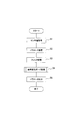
- step S ⁇ b> 1 of FIG. 2 the sensor value acquisition unit 7 acquires values (sensor values, measurement values) measured by the sensors 17, 19, 21, and 23. Specifically, the sensor value acquisition unit 7 acquires an image ahead of the host vehicle 33 captured by the image sensor 17 from the image sensor 17, and uses the yaw rate of the host vehicle 33 measured by the yaw rate sensor 19. And the vehicle speed V of the host vehicle 33 measured by the wheel speed sensor 21 is acquired from the wheel speed sensor 21, and various state quantities of the host vehicle 33 are acquired using the other in-vehicle sensors 23.
- the parameter estimation unit 9 which is an example of a curvature estimation unit, uses the sensor values acquired in step S1, and the lateral position P, yaw angle ⁇ , lateral speed Sw of the host vehicle 33, and the travel lane 35 Is calculated and stored in the memory 3b, for example.
- the lateral position P is a lane boundary line 29, 31 that divides a lane 35 in which the host vehicle 33 is traveling, and is closer to the host vehicle 33 (the lane boundary line 29 in FIG. 3) The distance in the lateral direction (direction perpendicular to the traveling direction of the lane 35, vehicle width direction) with the portion 33A closest to the lane boundary line of the host vehicle 33.
- FIG. 3 the lateral position P is a lane boundary line 29, 31 that divides a lane 35 in which the host vehicle 33 is traveling, and is closer to the host vehicle 33 (the lane boundary line 29 in FIG. 3)
- the distance in the lateral direction (direction perpendicular to the traveling direction of the lane 35, vehicle
- the parameter estimation unit 9 estimates the lateral position P of the host vehicle 33 from the positions of the lane boundary lines 29 and 31 in the image acquired in step S1.
- the lateral speed Vw is a lateral component in the lane 35 of the vehicle speed V of the host vehicle 33 as shown in FIG.
- the parameter estimation unit 9 estimates the lateral velocity Vw as follows. First, the parameter estimation unit 9 calculates the yaw angle ⁇ of the host vehicle 33 based on the positions and orientations of the lane boundary lines 29 and 31 in the image acquired in step S1. As shown in FIG. 3, the yaw angle ⁇ is an angle formed by the traveling direction ⁇ of the host vehicle 33 and the lane boundary lines 29 and 31.
- the parameter estimation unit 9 is provided in advance with a map that defines the relationship between the positions and orientations of the lane boundary lines 29 and 31 in a number of forward images of the host vehicle 33 and the yaw angle ⁇ of the host vehicle 33. By inputting the position and orientation of the lane boundary lines 29 and 31 in the acquired image to the map, the yaw angle ⁇ of the host vehicle 33 is calculated.
- the parameter estimation unit 9 calculates the lateral speed Vw by multiplying the vehicle speed V of the host vehicle 33 by sin ⁇ .
- the lateral speed Vw in the direction from the center of the lane 35 toward the direction closer to the host vehicle 33 (the lane boundary 29 in FIG. 3) is positive.
- the lateral speed Sw in the opposite direction is a negative value.
- the curvature C is the curvature of the lane boundary lines 29 and 31 (in other words, the curvature of the lane 35) when the lane 35 is viewed from above.
- the parameter estimation unit 9 estimates the curvature C from the shape of the lane boundary lines 29 and 31 appearing in the image acquired in step S1. In addition, about the positive / negative of the value of the curvature C, the curvature C when the lane 35 bends in the left direction as it goes up in FIG. 3 is made into a positive value, and the curvature C when turning in the opposite direction is made into a negative value. .
- step S3 the filter processing unit 11 performs a filtering process using the Kalman filter on the lateral position P, the lateral velocity Vw, and the curvature C estimated in step S2.
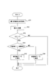
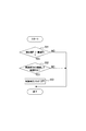
- step S4 the maximum allowable change rate acquisition unit 13 and the correction unit 15 perform a curvature change guard process on the curvature C estimated in step S2. This curvature change guard process will be described with reference to FIGS.
- the regulation unit 25 stores the regulation data shown in FIG. 5 in advance.
- the specified data is data that specifies the maximum allowable change rate G for the change rate in the curvature C for each vehicle speed V.
- the rate of change in curvature C is as follows. That is, the value of the curvature C at some time t 1 is C (t 1), the value of the curvature C at a later point in time t 2 is assumed to be C (t 2).
- the rate of change in the curvature C (t 2 ) is represented by K (C (t 2 ) ⁇ C (t 1 )) / (t 2 ⁇ t 1 ).
- K is a constant.
- the relationship between the vehicle speed V and the maximum allowable change rate G is such that the greater the vehicle speed V, the smaller the maximum allowable change rate G.
- the regulation data can be created, for example, as follows based on laws and regulations such as a road structure ordinance.
- the road structure ordinance prescribes the road curvature radius (minimum curve radius) and the road design speed in association with each other.
- the minimum distance of the clothoid section is 1/3 of the radius of curvature.
- the distance of the clothoid section to the curved road having the predetermined radius of curvature R is set to 1/3 of the radius of curvature R, and the curvature change rate (unit: 1 / m / s) in the clothoid section is calculated, and this is the maximum allowable change.
- G be the rate.
- the vehicle speed V is a vehicle speed obtained by adding a certain margin (for example, 30 km / h) to the design speed on the road having the curvature radius R defined by the road structure ordinance. And the data which matched said maximum permissible change rate G and said vehicle speed V are made into regulation data.
- the maximum allowable change rate acquisition unit 13 acquires the maximum allowable change rate G corresponding to the vehicle speed V acquired in step S1 from the regulation unit 25.
- the corresponding maximum allowable change rate G is 0.0104 (1 / m / s)
- the vehicle speed V is 60 (km / h)
- the corresponding maximum allowable change rate G is 0.0052 (1 / m / s).
- step S12 the value of curvature C estimated in step S2 of the previous cycle from the value of curvature C estimated in step S2 of the previous cycle (hereinafter referred to as current value C1).
- the correction unit 15 calculates the difference ⁇ obtained by subtracting (C2).
- the difference ⁇ corresponds to the rate of change in the current value C1.
- the previous value C2 is an example of the curvature C estimated in the past. When the previous value C2 is the current value, the previous value C2 may have been corrected later, or may not have been corrected.
- step S13 the correction unit 15 determines whether or not the absolute value of the difference ⁇ calculated in step S12 is larger than the maximum allowable change rate G acquired in step S11. If the absolute value of the difference ⁇ is greater than the maximum allowable change rate G, the process proceeds to step S14. On the other hand, in other cases, the correction unit 15 ends the curvature change guard process without correcting the current value C1.
- step S14 the correction unit 15 determines whether or not the current value C1 is greater than the previous value C2. If the current value C1 is larger than the previous value C2, the process proceeds to step S15. If the current value C1 is smaller than the previous value C2, the process proceeds to step S16.
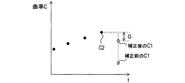
- step S15 the correction unit 15 corrects the current value C1 to a value “previous value C2 + G”. An example of this correction is shown in FIG. 6A.
- step S16 the correction unit 15 corrects the current value C1 to a value “previous value C2-G”. An example of this correction is shown in FIG. 6B.
- step S5 for example, the sensor value acquisition unit 7 and the parameter estimation unit 9 each output the sensor value acquired in step S1 and the parameter estimated in step S2 to the control device 5.
- the correction unit 15 outputs the corrected curvature C.
- the parameter C estimation unit 9 outputs the curvature C estimated in step S2 as it is.
- Control Process Performed by Control Device 5 The control process that the control device 5, that is, the CPU 5a repeatedly executes at predetermined time intervals will be described with reference to FIGS. In step S ⁇ b> 21 of FIG. 7, the control device 5 acquires sensor values and parameters (lateral position P, lateral velocity Vw, and curvature C) from the parameter estimation device 3.
- step S22 the control device 5 determines whether or not the control execution flag is on.
- This control execution flag is a variable indicating whether or not steering control is executed, for example. The initial value is on, and the control execution flag is turned on or off by processing described later.
- the control process proceeds to step S23, and when it is on, the control process proceeds to step S25.
- step S23 the control device 5 performs a steering control start determination process.
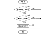
- This control start determination process will be described with reference to FIG.
- the control device 5 determines whether or not the lateral speed Vw is greater than a preset threshold value T1. When the lateral speed Vw is greater than the threshold value T1, the control start determination process proceeds to step S32. When the lateral speed Vw is equal to or less than the threshold value T1, the control device 5 ends the control start determination process.
- step S32 the control device 5 determines whether or not the lateral position P is smaller than a preset threshold value T2 (see FIG. 3). When the lateral position P is smaller than the threshold value T2, the control start determination process proceeds to step S33, and when it is equal to or greater than the threshold value T2, the control device 5 ends the control start determination process.
- step S33 the control device 5 turns on the control execution flag.
- the control device 5 determines whether or not the control execution flag is on. If the control execution flag is on, the control process proceeds to step S25. If the control execution flag is off, the control device 5 ends the control process.
- step S25 the control device 5 executes a process during control, that is, a steering control process.
- This steering control process will be described with reference to FIG.
- step S41 of FIG. 9 the control device 5 sets the target value of the lateral position P and the target value of the lateral speed Vw under the assumption that the lane in which the host vehicle 33 is traveling is a straight line.
- the target value of the lateral position P is a value larger than a threshold value T2 and a threshold value T3 described later.
- the target value of the lateral velocity Vw has a sufficiently small absolute value.
- the control device 5 calculates a required torque (hereinafter referred to as FF (feed forward) amount) necessary to reach the target value of the lateral position P and the target value of the lateral speed Vw.
- FF feed forward
- the control device 5 calculates a required torque (hereinafter referred to as a curvature FF amount) necessary for traveling according to the curvature C acquired in step S21.
- step S43 the control device 5 calculates a difference between the target values of the lateral position P and the lateral speed Vw and the actual values of the lateral position P and the lateral speed Vw, and requests torque ( Hereinafter, FB (feedback) amount) is calculated.
- FB feedback
- step S44 the control device 5 calculates the final required torque by adding the FF amount calculated in step S41, the curvature FF amount calculated in step S42, and the FB amount calculated in step S43. To do.
- step S45 the control device 5 outputs the required torque calculated in step S44 to the electric power steering device 27.
- step S ⁇ b> 26 the control device 5 performs a steering control process end determination process. This control end determination process will be described with reference to FIG.
- step S51 of FIG. 10 the control device 5 determines whether or not the lateral position P is larger than a preset threshold value T3 (see FIG. 3). If the lateral position P is greater than the threshold value T3, the control end determination process proceeds to step S52. If the lateral position P is equal to or less than the threshold value T3, the control device 5 ends the control end determination process.
- step S52 the control device 5 determines whether or not the condition that the lateral velocity Vw continues for a certain time and is within a preset range R is satisfied. If the condition is satisfied, the control end determination process proceeds to step S53. If the condition is not satisfied, the control device 5 ends the control end determination process.
- step S53 the control device 5 turns off the control execution flag. If the control execution flag is already off, the control device 5 maintains the control execution flag off state. 4). Effects Produced by Parameter Estimation Device 3 and Lane Departure Avoidance System 1
- the parameter estimation device 3 corrects the current value C1 of the curvature C when the difference ⁇ (an example of the change rate) in the curvature C exceeds the maximum allowable change rate G.
- the difference ⁇ between the current value C1 of the corrected curvature C and the previous value C2 of the curvature C is the maximum allowable change rate G.
- the parameter estimation device 3 acquires the maximum allowable change rate G corresponding to the vehicle speed V from the regulation unit 25. Therefore, the processing load for acquiring the maximum allowable change rate G can be reduced, and as a result, the maximum allowable change rate G with respect to the input of the vehicle speed V of the parameter estimation device 3 when estimating the curvature C is obtained. Responsiveness can be improved.
- the lane departure avoidance system 1 calculates the required torque using the curvature C corrected as necessary as described above. As a result, the response of the required torque to the change in the curvature C can be ensured, and the noise of the curvature C can be prevented from affecting the automatic steering.
- the relationship between the vehicle speed V and the maximum allowable change rate G is that the maximum allowable change rate G is smaller as the vehicle speed V is higher. This relationship coincides with the relationship between the vehicle speed V when the host vehicle 33 actually travels in the lane and the rate of change of the curvature C in the lane. As a result, the maximum allowable change rate G can be set to an appropriate value according to the vehicle speed V. As mentioned above, although embodiment of this invention was described, this invention can take a various form, without being limited to the said embodiment.
- the correction unit 15 When the current value C1 has a larger absolute value than the previous value C2, the correction unit 15 (when the curvature C changes in a direction in which the absolute value increases compared to the curvature C estimated in the past), although the above correction is performed, the correction may not be performed when the current value C1 is smaller in absolute value than the previous value C2.
- the parameter estimation device 3 may acquire the maximum allowable change rate G corresponding to the vehicle speed V from a facility outside the host vehicle 33.
- the method for correcting the current value C1 of the curvature C may be another method.
- the correction unit 15 sets the current value C1 of the corrected curvature C as a value “previous value C2 + ⁇ ”
- the correction unit 15 sets the current value C1 of the corrected curvature C as “previous value C2 + ⁇ ”.
- the value can be a value “C2- ⁇ ”. This ⁇ is, for example, a positive number and can be set to a value smaller than the maximum allowable change rate G.
- the difference ⁇ between the corrected current value C1 and the previous value C2 is a value ⁇ smaller than the maximum allowable change rate G.
- the parameter estimation device 3 may calculate the rate of change of the curvature C from the value of the curvature C estimated three or more times continuously. When the rate of change exceeds the maximum allowable rate of change G, part or all of the values of the curvature C that are three or more times can be corrected.
- the curvature C may be corrected for the value of the curvature C other than the current value C1.
- the correction unit 15 may detect afterwards the value of the curvature C estimated in the past and the corresponding change rate exceeds the maximum allowable change rate G, and correct the value of the curvature C.
- the functions of one component in the above embodiment may be distributed as a plurality of components, or the functions of a plurality of components may be integrated into one component. Further, at least a part of the configuration of the above embodiment may be replaced with a known configuration having the same function. Moreover, you may abbreviate
Landscapes
- Engineering & Computer Science (AREA)
- Transportation (AREA)
- Mechanical Engineering (AREA)
- Automation & Control Theory (AREA)
- Physics & Mathematics (AREA)
- General Physics & Mathematics (AREA)
- Mathematical Physics (AREA)
- Chemical & Material Sciences (AREA)
- Combustion & Propulsion (AREA)
- Steering Control In Accordance With Driving Conditions (AREA)
- Traffic Control Systems (AREA)
Abstract
曲率の最大許容変化率と車速との関係を規定した規定ユニットから、車速取得ユニットで取得した車速の値に対応する前記最大許容変化率の値を取得し、推定した曲率の値における変化率が前記最大許容変化率の値を超える場合、推定した曲率の値を、その変化率の値が前記最大許容変化率の値以下となるように補正する道路曲率推定装置である。
Description
本開示は道路曲率推定装置及び車線逸脱回避システムに関する。
自車両の前方を撮像し、その撮像画像において認識した車線の形状から、車線の曲率を推定する方法が知られている(特許文献1参照)。この方法で推定する曲率にはノイズが含まれる。特に、白線が薄くなっている場合や、路面ノイズが多い場合に、曲率のノイズが大きくなる。
特許文献1記載の技術では、現在より前の位置での車線の曲率を求め、その曲率に応じて曲率の最大許容変化量を設定することで、曲率の推定精度を向上させようとする。
特許文献1記載の技術では、最大許容変化量を設定するために、現在より前の位置での車線の曲率を求める必要がある。そのため、装置の処理負担が大きく、現在の位置における曲率を推定する際の応答性が低下するおそれがある。
本開示は、こうした問題に鑑みてなされたものであり、道路(車線)の曲率の推定精度が高く、応答性に優れた道路曲率推定装置及び車線逸脱回避システムを提供することを目的としている。
本開示の例示態様に関わる道路曲率推定装置は、自車両の前方を撮像した画像を取得する画像取得ユニットと、前記画像を用いて自車両が走行中の車線における曲率を推定する曲率推定ユニットと、自車両の車速を取得する車速取得ユニットと、前記曲率の最大許容変化率と車速との関係を規定した規定ユニットから、前記車速取得ユニットで取得した車速の値に対応する前記最大許容変化率の値を取得する最大許容変化率取得ユニットと、前記曲率推定ユニットで推定した曲率の値における変化率が前記最大許容変化率の値を超える場合、前記曲率推定ユニットで推定した曲率の値を、その変化率の値が前記最大許容変化率の値以下となるように補正する補正ユニットと、を備えている。
また、本開示の例示態様に関わる車線逸脱回避システムは、上記道路曲率推定装置と、この道路曲率推定装置で推定した前記曲率を用いて、前記自車両が車線に沿って走行するための操舵トルクを演算する操舵トルク演算装置と、を備えている。
また、本開示の例示態様に関わる車線逸脱回避システムは、上記道路曲率推定装置と、この道路曲率推定装置で推定した前記曲率を用いて、前記自車両が車線に沿って走行するための操舵トルクを演算する操舵トルク演算装置と、を備えている。
推定した道路の曲率の値における変化率が前記最大許容変化率の値を超える場合において、その推定した曲率の値をそのまま用いて推定結果とした仮定すると、上記曲率の変化率における最大許容変化率の値を超えた部分、すなわち、ノイズ成分により、曲線の推定精度が低下する恐れがある。
この点、本開示の例示態様に関わる道路曲率推定装置は、推定した道路の曲率の値における変化率が前記最大許容変化率の値を超える場合において、その推定した曲率の値を、その変化率の値が前記最大許容変化率の値以下となるように補正している。この補正により、推定した曲率の値に含まれるノイズの影響を低減し、道路(車線)の推定精度を向上させることができる。
この点、本開示の例示態様に関わる道路曲率推定装置は、推定した道路の曲率の値における変化率が前記最大許容変化率の値を超える場合において、その推定した曲率の値を、その変化率の値が前記最大許容変化率の値以下となるように補正している。この補正により、推定した曲率の値に含まれるノイズの影響を低減し、道路(車線)の推定精度を向上させることができる。
また、本開示の例示態様に関わる道路曲率推定装置は、前記曲率の最大許容変化率と車速との関係を規定した規定ユニットから、前記車速取得ユニットで取得した車速の値に対応する前記最大許容変化率の値を取得している。このため、道路曲率推定装置における最大許容変化率の値を取得する際の処理負荷を低減することができる。この結果、曲率を推定する際の道路曲率推定装置の、車速の入力に対する最大許容変化率の取得に関する応答性を向上させることができる。
本開示の実施形態を図面に基づき説明する。なお、以下の各実施形態相互において、互いに同一もしくは均等である部分には、図中、同一符号を付しており、同一符号の部分についてはその説明を援用する。
1.車線逸脱回避システム1の構成
車線逸脱回避システム1の構成を図1に基づき説明する。車線逸脱回避システム1は車両に搭載される車載装置である。以下では、車線逸脱回避システム1を搭載した車両33を自車両33とする。
車線逸脱回避システム1は、パラメータ推定装置3と、制御装置5とを備える。
車線逸脱回避システム1の構成を図1に基づき説明する。車線逸脱回避システム1は車両に搭載される車載装置である。以下では、車線逸脱回避システム1を搭載した車両33を自車両33とする。
車線逸脱回避システム1は、パラメータ推定装置3と、制御装置5とを備える。
パラメータ推定装置3は、例えば、プロセッサであるCPU(Central Processing Unit)3aと、RAM、ROM等の記憶媒体を少なくとも1つ含むメモリ3bと、を備えるコンピュータを中心に構成されている。パラメータ推定装置3、すなわちCPU3aは、例えばメモリ1bに記憶されたプログラムにより後述する処理を実行し、各種パラメータを推定する。
パラメータ推定装置3は、CPU3aにより実現される機能として、センサ値取得ユニット7と、パラメータ推定ユニット9と、フィルタ処理ユニット11と、最大許容変化率取得ユニット13と、補正ユニット15と、を備える。各ユニットの機能は後述する。
パラメータ推定装置3は、CPU3aにより実現される機能として、センサ値取得ユニット7と、パラメータ推定ユニット9と、フィルタ処理ユニット11と、最大許容変化率取得ユニット13と、補正ユニット15と、を備える。各ユニットの機能は後述する。
制御装置5は、例えば、プロセッサであるCPU5aと、RAM、ROM等の記憶媒体を少なくとも1つ含むメモリ5bと、を備える公知のコンピュータを中心に構成されている。制御装置5、すなわちCPU5aは、例えばメモリ1bに記憶されたプログラムにより後述する処理を実行し、要求トルク(操舵トルク)を算出する。
自車両33は、車線逸脱回避システム1に加えて、画像センサ17、ヨーレートセンサ19、車輪速センサ21、その他の車載センサ23、規定ユニット25、及び電動パワーステアリング装置27を備える。
画像センサ17は、自車両33の前方を撮像し、撮像された前方画像に基づく画像データを作成する。
ヨーレートセンサ19は、自車両33のヨーレートを検出する。
車輪速センサ21は、自車両33の車速Sを検出する。
その他の車載センサ23は自車両33の状態量を検出する。
規定データ記憶ユニット(規定ユニット)25は、例えばハードディスクドライブ等の記憶装置であって、後述する規定データを記憶している。
ヨーレートセンサ19は、自車両33のヨーレートを検出する。
車輪速センサ21は、自車両33の車速Sを検出する。
その他の車載センサ23は自車両33の状態量を検出する。
規定データ記憶ユニット(規定ユニット)25は、例えばハードディスクドライブ等の記憶装置であって、後述する規定データを記憶している。
電動パワーステアリング装置27は、ドライバの操舵をアシストする通常の機能に加えて、制御装置5から要求トルクを取得し、その要求トルクに従って、自動操舵を行う。なお、センサ値取得ユニット7は、画像取得ユニットおよび車速取得ユニットの一例である。パラメータ推定装置3は、道路曲率推定装置の一例である。制御装置5は、操舵トルク演算装置の一例である。
2.パラメータ推定装置3が実行する処理
パラメータ推定装置3、すなわちCPU3aが一定時間Δt毎に繰り返し実行する処理を図2~図6に基づき説明する。
図2のステップS1では、センサ値取得ユニット7が、上記センサ17、19、21、および23により計測された値(センサ値、計測値)を取得する。
具体的には、センサ値取得ユニット7は、画像センサ17により撮像された自車両33の前方の画像を画像センサ17から取得し、ヨーレートセンサ19により計測された自車両33のヨーレートをヨーレートセンサ19から取得し、車輪速センサ21により計測された自車両33の車速Vを車輪速センサ21から取得し、その他の車載センサ23を用いて自車両33の各種状態量を取得する。
パラメータ推定装置3、すなわちCPU3aが一定時間Δt毎に繰り返し実行する処理を図2~図6に基づき説明する。
図2のステップS1では、センサ値取得ユニット7が、上記センサ17、19、21、および23により計測された値(センサ値、計測値)を取得する。
具体的には、センサ値取得ユニット7は、画像センサ17により撮像された自車両33の前方の画像を画像センサ17から取得し、ヨーレートセンサ19により計測された自車両33のヨーレートをヨーレートセンサ19から取得し、車輪速センサ21により計測された自車両33の車速Vを車輪速センサ21から取得し、その他の車載センサ23を用いて自車両33の各種状態量を取得する。
ステップS2では、曲率推定ユニットの一例であるパラメータ推定ユニット9が、前記ステップS1で取得したセンサ値を用いて、自車両33の横位置P、ヨー角θ、および横速度Swと、走行車線35の曲率Cとを算出し、例えば上記メモリ3bに記憶する。
横位置Pとは、図3に示すように、自車両33が走行中の車線35を区画する車線境界線29、31のうち、自車両33に近い方(図3では車線境界線29)と、自車両33のうち、その車線境界線に最も近い部分33Aとの横方向(車線35の走行方向と直交する方向、車幅方向)における距離である。
なお、図3に示すように、部分33Aが車線35内にある(車線境界線29より右側にある)とき、横位置Pを正の値とし、部分33Aが車線35外にある(車線境界線29より左側にある)とき、横位置Pを負の値とする。
具体的には、パラメータ推定ユニット9は、前記ステップS1で取得した画像における車線境界線29および31の位置から、自車両33の横位置Pを推定する。
横位置Pとは、図3に示すように、自車両33が走行中の車線35を区画する車線境界線29、31のうち、自車両33に近い方(図3では車線境界線29)と、自車両33のうち、その車線境界線に最も近い部分33Aとの横方向(車線35の走行方向と直交する方向、車幅方向)における距離である。
なお、図3に示すように、部分33Aが車線35内にある(車線境界線29より右側にある)とき、横位置Pを正の値とし、部分33Aが車線35外にある(車線境界線29より左側にある)とき、横位置Pを負の値とする。
具体的には、パラメータ推定ユニット9は、前記ステップS1で取得した画像における車線境界線29および31の位置から、自車両33の横位置Pを推定する。
横速度Vwとは、図3に示すように、自車両33の車速Vのうち、車線35における横方向の成分である。パラメータ推定ユニット9は、以下のようにして横速度Vwを推定する。
まず、パラメータ推定ユニット9は、前記ステップS1で取得した画像における車線境界線29、31の位置および向きに基づき、自車両33のヨー角θを算出する。
ヨー角θとは、図3に示すように、自車両33の進行方向αと、車線境界線29、31とが成す角度である。
まず、パラメータ推定ユニット9は、前記ステップS1で取得した画像における車線境界線29、31の位置および向きに基づき、自車両33のヨー角θを算出する。
ヨー角θとは、図3に示すように、自車両33の進行方向αと、車線境界線29、31とが成す角度である。
なお、ヨー角θが変化すると、それに応じて、ステップS1で取得した画像における車線境界線29、31の位置及び向きが変化する。パラメータ推定ユニット9は、自車両33の多数の前方画像における車線境界線29、31の位置及び向きと、自車両33のヨー角θとの関係を規定するマップを予め備えており、ステップS1で取得した画像における車線境界線29、31の位置及び向きをそのマップに入力することで、自車両33のヨー角θを算出する。
次に、パラメータ推定ユニット9は、自車両33の車速Vにsinθを乗算することで横速度Vwを算出する。横速度Vwの値の正負については、車線35の中央から、車線境界線29、31のうち、自車両33に近い方(図3では車線境界線29)に向う方向の横速度Vwを正の値とし、その反対方向の横速度Swを負の値とする。
曲率Cは、車線35を上方から見たときの、車線境界線29、31の曲率(言い換えれば、車線35の曲率)である。パラメータ推定ユニット9は、前記ステップS1で取得した画像に表れる車線境界線29、31の形状から、曲率Cを推定する。なお、曲率Cの値の正負については、図3において上にゆくほど左方向に車線35が曲がるときの曲率Cを正の値とし、その反対方向に曲がるときの曲率Cを負の値とする。
図2に戻り、ステップS3では、フィルタ処理ユニット11が、前記ステップS2で推定した横位置P、横速度Vw、及び曲率Cに対し、カルマンフィルタを用いてフィルタ処理を行う。
ステップS4では、最大許容変化率取得ユニット13及び補正ユニット15が、前記ステップS2で推定した曲率Cに対し、曲率変化ガード処理を行う。この曲率変化ガード処理を図4~図6に基づき説明する。
規定ユニット25は、図5に示す規定データを予め記憶している。
この規定データは、曲率Cにおける変化率に関する最大許容変化率Gを車速Vごとに規定したデータである。曲率Cにおける変化率とは、以下のものである。
すなわち、ある時点t1において曲率Cの値がC(t1)であり、その後の時点t2において曲率Cの値がC(t2)であったとする。曲率C(t2)における変化率は、K(C(t2)-C(t1))/(t2-t1)で表される。ここで、Kは定数である。
この規定データは、曲率Cにおける変化率に関する最大許容変化率Gを車速Vごとに規定したデータである。曲率Cにおける変化率とは、以下のものである。
すなわち、ある時点t1において曲率Cの値がC(t1)であり、その後の時点t2において曲率Cの値がC(t2)であったとする。曲率C(t2)における変化率は、K(C(t2)-C(t1))/(t2-t1)で表される。ここで、Kは定数である。
規定データにおいて、車速Vと最大許容変化率Gとの関係は、車速Vが大きいほど、最大許容変化率Gが小さいという関係である。
規定データは、道路構造令等の法規に基づき、例えば、以下のようにして作成することができる。道路構造令は、道路の曲率半径(最小カーブ半径)と、道路の設計速度とを対応付けて規定している。また、道路構造令は、クロソイド区間の最小距離は曲率半径の1/3としている。
規定データは、道路構造令等の法規に基づき、例えば、以下のようにして作成することができる。道路構造令は、道路の曲率半径(最小カーブ半径)と、道路の設計速度とを対応付けて規定している。また、道路構造令は、クロソイド区間の最小距離は曲率半径の1/3としている。
所定の曲率半径Rを有する曲線道路に至るクロソイド区間の距離を曲率半径Rの1/3とし、そのクロソイド区間における曲率変化率(単位は1/m/s)を算出し、これを最大許容変化率Gとする。一方、道路構造令が規定する、曲率半径Rの道路における設計速度に、一定のマージン(例えば30km/h)を付加した車速を車速Vとする。そして、上記の最大許容変化率Gと上記の車速Vとを対応付けたデータを規定データとする。
図4のステップS11では、最大許容変化率取得ユニット13が、前記ステップS1で取得した車速Vに対応する最大許容変化率Gを、規定ユニット25から取得する。例えば、車速Vが50(km/h)である場合、それに対応する最大許容変化率Gは0.0104(1/m/s)であり、車速Vが60(km/h)である場合、それに対応する最大許容変化率Gは0.0052(1/m/s)である。
ステップS12では、直前サイクルの前記ステップS2で推定した曲率Cの値(以下、今回値C1とする)から、その一回前のサイクルの前記ステップS2で推定した曲率Cの値(以下、前回値C2とする)を差し引いた差分Δを補正ユニット15が演算する。
なお、差分Δは、今回値C1における変化率に該当する。また、前回値C2は、過去に推定した曲率Cの一例である。前回値C2は、それが今回値であったとき、後述する補正を受けたものであってもよいし、補正を受けなかったものであってもよい。
なお、差分Δは、今回値C1における変化率に該当する。また、前回値C2は、過去に推定した曲率Cの一例である。前回値C2は、それが今回値であったとき、後述する補正を受けたものであってもよいし、補正を受けなかったものであってもよい。
ステップS13では、前記ステップS12で演算した差分Δの絶対値が、前記ステップS11で取得した最大許容変化率Gより大きいか否かを補正ユニット15が判断する。差分Δの絶対値が最大許容変化率Gより大きい場合は、処理はステップS14に進む。一方、それ以外の場合は、補正ユニット15は、今回値C1を補正することなく、曲率変化ガード処理を終了する。
ステップS14では、今回値C1が前回値C2より大きいか否かを補正ユニット15が判断する。今回値C1が前回値C2より大きい場合は、処理はステップS15に進み、今回値C1が前回値C2より小さい場合は、処理はステップS16に進む。
ステップS15では、補正ユニット15が、今回値C1を、「前回値C2+G」という値に補正する。この補正の例を図6Aに示す。
ステップS16では、補正ユニット15が、今回値C1を、「前回値C2-G」という値に補正する。この補正の例を図6Bに示す。
ステップS16では、補正ユニット15が、今回値C1を、「前回値C2-G」という値に補正する。この補正の例を図6Bに示す。
図2に戻り、ステップS5では、例えば、センサ値取得ユニット7およびパラメータ推定ユニット9は、それぞれ、前記ステップS1で取得したセンサ値と、前記ステップS2で推定したパラメータとを、制御装置5に出力する。曲率Cについては、前記ステップS4において補正した場合は、補正ユニット15が補正後の曲率Cを出力する。また、前記ステップS4において補正しなかった場合は、パラメータ推定ユニット9が前記ステップS2で推定した曲率Cをそのままの値で出力する。
3.制御装置5が実行する制御処理
制御装置5、すなわちCPU5aが所定時間ごとに繰り返し実行する制御処理を図7~図10に基づき説明する。図7のステップS21では、制御装置5は、パラメータ推定装置3から、センサ値及びパラメータ(横位置P、横速度Vw、及び曲率C)を取得する。
制御装置5、すなわちCPU5aが所定時間ごとに繰り返し実行する制御処理を図7~図10に基づき説明する。図7のステップS21では、制御装置5は、パラメータ推定装置3から、センサ値及びパラメータ(横位置P、横速度Vw、及び曲率C)を取得する。
ステップS22では、制御装置5は、制御実行フラグがオンであるか否かを判断する。この制御実行フラグは、例えば操舵制御を実行するか否かを表す変数であり、初期値はオンとなっており、後述する処理によりオン又はオフとなる。制御実行フラグがオフである場合は、制御処理はステップS23に進み、オンである場合は制御処理はステップS25に進む。
ステップS23では、制御装置5は、操舵制御の開始判定処理を行う。この制御開始判定処理を図8に基づき説明する。
図8のステップS31では、制御装置5は、横速度Vwが予め設定された閾値T1より大きいか否かを判断する。
横速度Vwが閾値T1より大きい場合は、制御開始判定処理はステップS32に進み、閾値T1以下である場合は、制御装置5は、制御開始判定処理を終了する。
図8のステップS31では、制御装置5は、横速度Vwが予め設定された閾値T1より大きいか否かを判断する。
横速度Vwが閾値T1より大きい場合は、制御開始判定処理はステップS32に進み、閾値T1以下である場合は、制御装置5は、制御開始判定処理を終了する。
ステップS32では、制御装置5は、横位置Pが予め設定された閾値T2(図3参照)より小さいか否かを判断する。横位置Pが閾値T2より小さい場合は、制御開始判定処理はステップS33に進み、閾値T2以上である場合は、制御装置5は、制御開始判定処理を終了する。
ステップS33では、制御装置5は、制御実行フラグをオンにする。
図7に戻り、ステップS24では、制御装置5は、制御実行フラグがオンであるか否かを判断する。制御実行フラグがオンである場合は、制御処理はステップS25に進み、制御実行フラグがオフである場合は、制御装置5は、本制御処理を終了する。
図7に戻り、ステップS24では、制御装置5は、制御実行フラグがオンであるか否かを判断する。制御実行フラグがオンである場合は、制御処理はステップS25に進み、制御実行フラグがオフである場合は、制御装置5は、本制御処理を終了する。
ステップS25では、制御装置5は、制御中処理、すなわち操舵制御処理を実行する。この操舵制御処理を図9に基づき説明する。
図9のステップS41では、制御装置5は、自車両33が走行中の車線が直線であるという仮定の下で、横位置Pの目標値、及び横速度Vwの目標値を設定する。横位置Pの目標値は、閾値T2及び後述する閾値T3よりも大きい値である。横速度Vwの目標値は、その絶対値が十分小さい値である。
図9のステップS41では、制御装置5は、自車両33が走行中の車線が直線であるという仮定の下で、横位置Pの目標値、及び横速度Vwの目標値を設定する。横位置Pの目標値は、閾値T2及び後述する閾値T3よりも大きい値である。横速度Vwの目標値は、その絶対値が十分小さい値である。
次に、制御装置5は、横位置Pの目標値及び横速度Vwの目標値に到達するために必要な要求トルク(以下、FF(フィードフォワード)量とする)を算出する。
ステップS42では、制御装置5は、前記ステップS21で取得した曲率Cに応じて走行するために必要な要求トルク(以下、曲率分FF量とする)を演算する。
ステップS42では、制御装置5は、前記ステップS21で取得した曲率Cに応じて走行するために必要な要求トルク(以下、曲率分FF量とする)を演算する。
ステップS43では、制御装置5は、横位置P及び横速度Vwの目標値と、横位置P及び横速度Vwそれぞれの実際の値との差を算出し、その差を減少させるための要求トルク(以下、FB(フィードバック)量とする)を演算する。
ステップS44では、制御装置5は、前記ステップS41で演算したFF量、前記ステップS42で演算した曲率分FF量、及び前記ステップS43で演算したFB量を加算して、最終的な要求トルクを演算する。
ステップS45では、制御装置5は、前記ステップS44で演算した要求トルクを電動パワーステアリング装置27に出力する。
図7に戻り、ステップS26では、制御装置5は、操舵制御処理終了の判定処理を行う。この制御終了判定処理を図10に基づき説明する。
図10のステップS51では、制御装置5は、横位置Pが予め設定された閾値T3(図3参照)より大きいか否かを判断する。横位置Pが閾値T3より大きい場合は、制御終了判定処理は、ステップS52に進み、横位置Pが閾値T3以下である場合は、制御装置5は、制御終了判定処理を終了する。
図7に戻り、ステップS26では、制御装置5は、操舵制御処理終了の判定処理を行う。この制御終了判定処理を図10に基づき説明する。
図10のステップS51では、制御装置5は、横位置Pが予め設定された閾値T3(図3参照)より大きいか否かを判断する。横位置Pが閾値T3より大きい場合は、制御終了判定処理は、ステップS52に進み、横位置Pが閾値T3以下である場合は、制御装置5は、制御終了判定処理を終了する。
ステップS52では、制御装置5は、横速度Vwが一定時間継続して、予め設定された範囲R内であるという条件を満たすか否かを判断する。その条件を満たす場合は、制御終了判定処理はステップS53に進み、その条件を満たさない場合は、制御装置5は、制御終了判定処理を終了する。
ステップS53では、制御装置5は、制御実行フラグをオフにする。既に制御実行フラグがオフであった場合は、制御装置5は、その制御実行フラグオフ状態を維持する。
4.パラメータ推定装置3及び車線逸脱回避システム1が奏する効果
パラメータ推定装置3は、曲率Cにおける差分Δ(変化率の一例)が最大許容変化率Gを超える場合、曲率Cの今回値C1を補正する。補正後の曲率Cの今回値C1と、曲率Cの前回値C2との差分Δは、最大許容変化率Gとなる。そのことにより、曲率Cにおけるノイズの影響を低減し、曲率Cの推定精度を高めることができる。
4.パラメータ推定装置3及び車線逸脱回避システム1が奏する効果
パラメータ推定装置3は、曲率Cにおける差分Δ(変化率の一例)が最大許容変化率Gを超える場合、曲率Cの今回値C1を補正する。補正後の曲率Cの今回値C1と、曲率Cの前回値C2との差分Δは、最大許容変化率Gとなる。そのことにより、曲率Cにおけるノイズの影響を低減し、曲率Cの推定精度を高めることができる。
次に、パラメータ推定装置3は、規定ユニット25から、車速Vに対応する最大許容変化率Gを取得する。そのため、最大許容変化率Gを取得するための処理負担が軽くすることができ、その結果、曲率Cを推定する際のパラメータ推定装置3の車速Vの入力に対する、最大許容変化率Gの取得に関する応答性を向上させることができる。
さらに、車線逸脱回避システム1は、上記のように必要に応じて補正した曲率Cを用いて要求トルクを演算する。そのことにより、曲率Cの変化に対する要求トルクの応答性を確保するとともに、曲率Cのノイズが自動操舵に影響してしまうことを抑制できる。
車速Vと最大許容変化率Gとの関係は、車速Vが大きいほど、最大許容変化率Gが小さいという関係である。この関係は、自車両33が実際に車線を走行するときの車速Vと、その車線における曲率Cの変化率との関係と一致する。そのことにより、最大許容変化率Gを、車速Vに応じた適切な値とすることができる。
以上、本発明の実施形態について説明したが、本発明は上記実施形態に限定されることなく、種々の形態を採り得る。
以上、本発明の実施形態について説明したが、本発明は上記実施形態に限定されることなく、種々の形態を採り得る。
補正ユニット15は、今回値C1が、前回値C2よりも絶対値が大きい場合(曲率Cが、過去に推定した曲率Cと比べて、絶対値が増加する方向に変化している場合)は、上記の補正を行うが、今回値C1が、前回値C2よりも絶対値が小さい場合は補正を行わないようにしてもよい。
この場合、補正の頻度が低下するので、パラメータ推定装置3の処理負担を軽減できる。なお、曲率Cの絶対値が減少する方向に変化している場合、自動操舵の制御は時間の経過とともに弱くなるので、補正を行わなくても、曲率Cのノイズの影響が比較的小さい。
パラメータ推定装置3は、自車両33の外部の施設から、車速Vに対応する最大許容変化率Gを取得してもよい。
曲率Cの今回値C1を補正する方法は他の方法であってもよい。例えば、前記ステップS15において、補正ユニット15は、補正後の曲率Cの今回値C1を、「前回値C2+δ」という値とし、前記ステップS16において、補正後の曲率Cの今回値C1を、「前回値C2-δ」という値とすることができる。このδは、例えば、正の数であって、最大許容変化率Gよりも小さい値とすることができる。この場合、補正後の今回値C1と、前回値C2との差分Δは、最大許容変化率Gより小さい値δとなる。
曲率Cの今回値C1を補正する方法は他の方法であってもよい。例えば、前記ステップS15において、補正ユニット15は、補正後の曲率Cの今回値C1を、「前回値C2+δ」という値とし、前記ステップS16において、補正後の曲率Cの今回値C1を、「前回値C2-δ」という値とすることができる。このδは、例えば、正の数であって、最大許容変化率Gよりも小さい値とすることができる。この場合、補正後の今回値C1と、前回値C2との差分Δは、最大許容変化率Gより小さい値δとなる。
パラメータ推定装置3は、連続して3回以上推定した曲率Cの値から、該曲率Cの変化率を算出してもよい。そして、その変化率が最大許容変化率Gを超える場合、その3回以上の曲率Cの値のうち、一部又は全部を補正することができる。
曲率Cの補正は、その今回値C1以外の曲率Cの値に対し行ってもよい。例えば、補正ユニット15は、過去に推定した曲率Cの値のうち、対応する変化率が最大許容変化率Gを超えるものを事後的に検出し、その曲率Cの値を補正してもよい。
上記実施形態における1つの構成要素が有する機能を複数の構成要素として分散させたり、複数の構成要素が有する機能を1つの構成要素に統合させたりしてもよい。また、上記実施形態の構成の少なくとも一部を、同様の機能を有する公知の構成に置き換えてもよい。また、上記実施形態の構成の一部を省略してもよい。また、上記実施形態の構成の少なくとも一部を、他の上記実施形態の構成に対して付加又は置換してもよい。なお、特許請求の範囲に記載した文言のみによって特定される技術思想に含まれるあらゆる態様が本発明の実施形態である。
上述したパラメータ推定装置3の他、当該パラメータ推定装置3を構成要素とするシステム、当該パラメータ推定装置3としてコンピュータを機能させるためのプログラム、このプログラムを記録した媒体、曲率推定方法等、種々の形態で本発明を実現することもできる。
なお、本出願は、日本特許出願2015-130160を基礎として優先権を主張するものであり、この優先権の基礎となる日本特許出願の開示内容は、参照書類として本出願に組み込まれている。
なお、本出願は、日本特許出願2015-130160を基礎として優先権を主張するものであり、この優先権の基礎となる日本特許出願の開示内容は、参照書類として本出願に組み込まれている。
1…車線逸脱回避システム、3…パラメータ推定装置、5…制御装置、7…センサ値取得ユニット、9…パラメータ推定ユニット、11…フィルタ処理ユニット、13…最大許容変化率取得ユニット、15…補正ユニット、17…画像センサ、19…ヨーレートセンサ、21…車輪速センサ、23…その他の車載センサ、25…規定ユニット、27…電動パワーステアリング装置、29、31…車線境界線、33…自車両、35…車線
Claims (11)
- 自車両の前方を撮像した画像を取得する画像取得ユニット(7)と、
前記画像を用いて自車両が走行中の車線における曲率を推定する曲率推定ユニット(9)と、
自車両の車速を取得する車速取得ユニット(7)と、
前記曲率の最大許容変化率と車速との関係を規定した規定ユニットから、前記車速取得ユニットで取得した車速の値に対応する前記最大許容変化率の値を取得する最大許容変化率取得ユニット(13)と、
前記曲率推定ユニットで推定した曲率の値における変化率が前記最大許容変化率の値を超える場合、前記曲率推定ユニットで推定した曲率の値を、その変化率の値が前記最大許容変化率の値以下となるように補正する補正ユニット(15)と、
を備えることを特徴とする道路曲率推定装置(3)。 - 請求項1に記載の道路曲率推定装置であって、
前記補正ユニットは、前記曲率推定ユニットで推定した曲率の値を、その変化率が前記最大許容変化率となるように補正することを特徴とする道路曲率推定装置。 - 請求項1又は2に記載の道路曲率推定装置であって、
前記曲率推定ユニットで推定した前記曲率の値である今回の値が、過去に推定した前記曲率の値である過去値と比べて、前記曲率の今回値の絶対値が増加する方向に変化していることを条件として、前記補正ユニットは、上記曲率の今回値の補正を行うことを特徴とする道路曲率推定装置。 - 請求項2に記載の道路曲率推定装置であって、
前記曲率推定ユニットで推定した前記曲率の値である今回の値が、過去に推定した前記曲率の値である過去値と比べて、前記曲率の今回値の絶対値が増加する方向に変化していることを条件として、前記補正ユニットは、上記曲率の今回値の補正を行うことを特徴とする道路曲率推定装置。 - 請求項1に記載の道路曲率推定装置であって、
前記規定ユニットにおける前記車速と前記最大許容変化率との関係は、前記車速が大きいほど、前記最大許容変化率が小さい関係であることを特徴とする道路曲率推定装置。 - 請求項2に記載の道路曲率推定装置であって、
前記規定ユニットにおける前記車速と前記最大許容変化率との関係は、前記車速が大きいほど、前記最大許容変化率が小さい関係であることを特徴とする道路曲率推定装置。 - 請求項3に記載の道路曲率推定装置であって、
前記規定ユニットにおける前記車速と前記最大許容変化率との関係は、前記車速が大きいほど、前記最大許容変化率が小さい関係であることを特徴とする道路曲率推定装置。 - 請求項1に記載の道路曲率推定装置と、
前記道路曲率推定装置で推定した前記曲率を用いて、前記自車両が車線に沿って走行するための操舵トルクを演算する操舵トルク演算装置(5)と、
を備えることを特徴とする車線逸脱回避システム(1)。 - 請求項8に記載の車線逸脱回避システムであって、
前記補正ユニットは、前記曲率推定ユニットで推定した曲率の値を、その変化率が前記最大許容変化率となるように補正することを特徴とする車線逸脱回避システム。 - 請求項8に記載の車線逸脱回避システムであって、
前記曲率推定ユニットで推定した前記曲率の値である今回の値が、過去に推定した前記曲率の値である過去値と比べて、前記曲率の今回値の絶対値が増加する方向に変化していることを条件として、前記補正ユニットは、上記曲率の今回値の補正を行うことを特徴とする車線逸脱回避システム。 - 請求項8に記載の車線逸脱回避システムであって、
前記規定ユニットにおける前記車速と前記最大許容変化率との関係は、前記車速が大きいほど、前記最大許容変化率が小さい関係であることを特徴とする車線逸脱回避システム。
Applications Claiming Priority (2)
| Application Number | Priority Date | Filing Date | Title |
|---|---|---|---|
| JP2015130160A JP2017016259A (ja) | 2015-06-29 | 2015-06-29 | 道路曲率推定装置及び車線逸脱回避システム |
| JP2015-130160 | 2015-06-29 |
Publications (1)
| Publication Number | Publication Date |
|---|---|
| WO2017002816A1 true WO2017002816A1 (ja) | 2017-01-05 |
Family
ID=57608493
Family Applications (1)
| Application Number | Title | Priority Date | Filing Date |
|---|---|---|---|
| PCT/JP2016/069162 Ceased WO2017002816A1 (ja) | 2015-06-29 | 2016-06-28 | 道路曲率推定装置及び車線逸脱回避システム |
Country Status (2)
| Country | Link |
|---|---|
| JP (1) | JP2017016259A (ja) |
| WO (1) | WO2017002816A1 (ja) |
Cited By (2)
| Publication number | Priority date | Publication date | Assignee | Title |
|---|---|---|---|---|
| CN115892001A (zh) * | 2022-12-22 | 2023-04-04 | 知行汽车科技(苏州)股份有限公司 | 一种弯道车速控制方法、装置、电子设备及存储介质 |
| US20240326790A1 (en) * | 2023-03-27 | 2024-10-03 | Hyundai Motor Company | Object Perception Method For Vehicle And Object Perception Apparatus |
Families Citing this family (1)
| Publication number | Priority date | Publication date | Assignee | Title |
|---|---|---|---|---|
| JP6880590B2 (ja) | 2016-08-02 | 2021-06-02 | いすゞ自動車株式会社 | 操舵補助装置及び操舵補助方法 |
Citations (4)
| Publication number | Priority date | Publication date | Assignee | Title |
|---|---|---|---|---|
| JP2005346304A (ja) * | 2004-06-01 | 2005-12-15 | Toyota Motor Corp | 道路パラメータ算出装置および車両挙動制御装置 |
| JP2007011492A (ja) * | 2005-06-28 | 2007-01-18 | Toyota Motor Corp | 走行路検出装置 |
| JP2009025081A (ja) * | 2007-07-18 | 2009-02-05 | Advics:Kk | 路面勾配推定装置 |
| JP2014109795A (ja) * | 2012-11-30 | 2014-06-12 | Toyota Motor Corp | 車両位置推定装置 |
-
2015
- 2015-06-29 JP JP2015130160A patent/JP2017016259A/ja active Pending
-
2016
- 2016-06-28 WO PCT/JP2016/069162 patent/WO2017002816A1/ja not_active Ceased
Patent Citations (4)
| Publication number | Priority date | Publication date | Assignee | Title |
|---|---|---|---|---|
| JP2005346304A (ja) * | 2004-06-01 | 2005-12-15 | Toyota Motor Corp | 道路パラメータ算出装置および車両挙動制御装置 |
| JP2007011492A (ja) * | 2005-06-28 | 2007-01-18 | Toyota Motor Corp | 走行路検出装置 |
| JP2009025081A (ja) * | 2007-07-18 | 2009-02-05 | Advics:Kk | 路面勾配推定装置 |
| JP2014109795A (ja) * | 2012-11-30 | 2014-06-12 | Toyota Motor Corp | 車両位置推定装置 |
Cited By (3)
| Publication number | Priority date | Publication date | Assignee | Title |
|---|---|---|---|---|
| CN115892001A (zh) * | 2022-12-22 | 2023-04-04 | 知行汽车科技(苏州)股份有限公司 | 一种弯道车速控制方法、装置、电子设备及存储介质 |
| US20240326790A1 (en) * | 2023-03-27 | 2024-10-03 | Hyundai Motor Company | Object Perception Method For Vehicle And Object Perception Apparatus |
| US12576837B2 (en) * | 2023-03-27 | 2026-03-17 | Hyundai Motor Company | Object perception method for vehicle and object perception apparatus |
Also Published As
| Publication number | Publication date |
|---|---|
| JP2017016259A (ja) | 2017-01-19 |
Similar Documents
| Publication | Publication Date | Title |
|---|---|---|
| CN109421709B (zh) | 车辆的驾驶辅助装置 | |
| US10378890B2 (en) | Apparatus and method for determining wheel alignment change of vehicle | |
| EP3492348B1 (en) | Steering assistance device and steering assistance method | |
| US10147003B2 (en) | Lane detection device and method thereof, curve starting point detection device and method thereof, and steering assistance device and method thereof | |
| CN105774801B (zh) | 用于引导车道上的车辆的方法和设备 | |
| JP6413953B2 (ja) | 車線逸脱回避システム | |
| CN109649477B (zh) | 驾驶支持控制系统 | |
| US10759473B2 (en) | Neutral point detection device and steering control system | |
| CN107709141B (zh) | 车道脱离避免装置 | |
| US20140129084A1 (en) | Control apparatus of vehicle for changing lane and control method of the same | |
| KR101896720B1 (ko) | 자동 차선 변경 제어 시스템 | |
| JP6414524B2 (ja) | 車両制御装置、及び走路信頼度判定方法 | |
| US9731756B2 (en) | Drive assist control apparatus | |
| US20200307612A1 (en) | Vehicle control device | |
| JP5287441B2 (ja) | 走行制御装置 | |
| JP5150958B2 (ja) | 車両走行支援装置、車両、車両走行支援プログラム | |
| JP2015189410A (ja) | 車両の車線逸脱防止制御装置 | |
| US9862414B2 (en) | Method and device for compensating a steering wheel angle signal, which is subject to an offset, in a vehicle | |
| WO2017002816A1 (ja) | 道路曲率推定装置及び車線逸脱回避システム | |
| KR20160059823A (ko) | 차선 유지보조 시스템 및 방법 | |
| JP5189316B2 (ja) | ヨーレートセンサの出力判定装置および追従先行車判定装置 | |
| JP5664531B2 (ja) | 追従制御装置 | |
| JP2009202673A (ja) | 運転支援装置 | |
| JP2014210456A (ja) | 車両の操舵制御装置 | |
| JP6670226B2 (ja) | 車両制御装置 |
Legal Events
| Date | Code | Title | Description |
|---|---|---|---|
| 121 | Ep: the epo has been informed by wipo that ep was designated in this application |
Ref document number: 16817924 Country of ref document: EP Kind code of ref document: A1 |
|
| NENP | Non-entry into the national phase |
Ref country code: DE |
|
| 122 | Ep: pct application non-entry in european phase |
Ref document number: 16817924 Country of ref document: EP Kind code of ref document: A1 |