WO2017002810A1 - 計量装置 - Google Patents
計量装置 Download PDFInfo
- Publication number
- WO2017002810A1 WO2017002810A1 PCT/JP2016/069147 JP2016069147W WO2017002810A1 WO 2017002810 A1 WO2017002810 A1 WO 2017002810A1 JP 2016069147 W JP2016069147 W JP 2016069147W WO 2017002810 A1 WO2017002810 A1 WO 2017002810A1
- Authority
- WO
- WIPO (PCT)
- Prior art keywords
- stepping motor
- control signal
- gate
- control unit
- current value
- Prior art date
- Legal status (The legal status is an assumption and is not a legal conclusion. Google has not performed a legal analysis and makes no representation as to the accuracy of the status listed.)
- Ceased
Links
Images

Classifications
-
- B—PERFORMING OPERATIONS; TRANSPORTING
- B65—CONVEYING; PACKING; STORING; HANDLING THIN OR FILAMENTARY MATERIAL
- B65G—TRANSPORT OR STORAGE DEVICES, e.g. CONVEYORS FOR LOADING OR TIPPING, SHOP CONVEYOR SYSTEMS OR PNEUMATIC TUBE CONVEYORS
- B65G65/00—Loading or unloading
- B65G65/30—Methods or devices for filling or emptying bunkers, hoppers, tanks, or like containers, of interest apart from their use in particular chemical or physical processes or their application in particular machines, e.g. not covered by a single other subclass
- B65G65/34—Emptying devices
- B65G65/40—Devices for emptying otherwise than from the top
-
- G—PHYSICS
- G01—MEASURING; TESTING
- G01G—WEIGHING
- G01G13/00—Weighing apparatus with automatic feed or discharge for weighing-out batches of material
- G01G13/02—Means for automatically loading weigh pans or other receptacles, e.g. disposable containers, under control of the weighing mechanism
- G01G13/04—Means for automatically loading weigh pans or other receptacles, e.g. disposable containers, under control of the weighing mechanism involving dribble-feed means controlled by the weighing mechanism to top up the receptacle to the target weight
- G01G13/06—Means for automatically loading weigh pans or other receptacles, e.g. disposable containers, under control of the weighing mechanism involving dribble-feed means controlled by the weighing mechanism to top up the receptacle to the target weight wherein the main feed is effected by gravity from a hopper or chute
-
- G—PHYSICS
- G01—MEASURING; TESTING
- G01G—WEIGHING
- G01G19/00—Weighing apparatus or methods adapted for special purposes not provided for in the preceding groups
- G01G19/387—Weighing apparatus or methods adapted for special purposes not provided for in the preceding groups for combinatorial weighing, i.e. selecting a combination of articles whose total weight or number is closest to a desired value
-
- H—ELECTRICITY
- H02—GENERATION; CONVERSION OR DISTRIBUTION OF ELECTRIC POWER
- H02P—CONTROL OR REGULATION OF ELECTRIC MOTORS, ELECTRIC GENERATORS OR DYNAMO-ELECTRIC CONVERTERS; CONTROLLING TRANSFORMERS, REACTORS OR CHOKE COILS
- H02P8/00—Arrangements for controlling dynamo-electric motors rotating step by step
- H02P8/36—Protection against faults, e.g. against overheating or step-out; Indicating faults
- H02P8/38—Protection against faults, e.g. against overheating or step-out; Indicating faults the fault being step-out
Definitions
- One aspect of the present invention relates to a weighing device that varies a control signal output to a gate of a hopper.
- Patent Document 1 discloses a combination weigher.
- this combination weigher when the hopper gate is driven to open and close, the torque applied to the motor shaft of the stepping motor is measured in advance using a torque measuring instrument (see, for example, paragraph 0036). Specifically, based on the proportional relationship between the torque applied to the motor shaft of the stepping motor and the drive current of the stepping motor, the minimum drive current required to open the hopper gate from the fully closed position to the fully open position is measured. Then, the minimum drive current required for the closing operation from the fully open position to the fully closed position is measured (see, for example, paragraphs 0037 to 0042). Thereby, the power consumption of the stepping motor is reduced.
- Patent Document 1 sets the gate drive current in the hopper based on the torque required to open and close the hopper as described above. Therefore, it is necessary to attach a torque measuring device to the motor shaft of the stepping motor related to opening and closing of the hopper gate. In order to realize this method, it is necessary to review the design around at least the stepping motor in order to secure a space for mounting the torque measuring device.
- one aspect of the present invention is to detect the presence or absence of stepping out of the drive unit based on the signal from the motor without using the torque measuring instrument as described above, and to change the control signal to the drive unit based on the detected result.
- An object of the present invention is to provide a weighing device that can be used.
- a weighing device has a gate, and by opening and closing the gate, a hopper that discharges an object to be weighed that is input from the outside and is temporarily retained, and a drive that drives the gate to open and close And a control unit that controls the drive unit by varying a control signal output to the drive unit.
- the control unit detects a step-out of the drive unit during the gate opening / closing drive, and detects the detection. Based on the presence / absence of the out-of-step, the control signal output to the drive unit is varied.
- One aspect of the present invention provides a weighing device that can detect the presence or absence of a step out of a drive unit based on a signal from a motor without using a torque measuring instrument, and can vary a control signal to the drive unit based on the detected result. For the purpose.
- FIG. 1 is a figure for explaining the outline of the whole combination measuring device 1 in one embodiment.
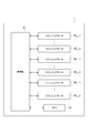
- FIG. 2 is a block diagram for explaining electrical coupling in the combination weighing device 1 according to one embodiment.
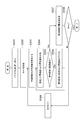
- FIG. 3 is a flowchart for setting a new current value based on the current value at the time of step-out in the control unit as an initial setting.
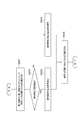
- FIG. 4 is a flowchart for explaining the operation of correcting the current value when the stepping motor steps out during operation using the current value determined in the flowchart shown in FIG.
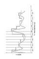
- FIG. 5 is a diagram for explaining a specific example of the set current value.
- FIG. 6 is an enlarged view showing a part of the fourth area in order to explain a specific example of re-dividing the fourth area into three areas.
- FIG. 1 is a figure for explaining the outline of the whole combination measuring device in one embodiment.
- a combination weighing device (metering device) 1 receives an object to be weighed (denoted as M in FIG. 1) from a supply device 100.
- the combination weighing device 1 performs combination weighing on the received objects to be weighed.
- the object to be weighed may be, for example, food such as a snack, or may be a metal part such as a nut or a bolt. That is, any object to be weighed may be used as long as a desired mass value is weighed in combination when a predetermined amount is supplied to a plurality of hoppers.
- the supply device 100 is a member that conveys an object to be weighed supplied by a user and drops it against the dispersion unit 2.
- the object to be weighed is put into the combination weighing device 1 by the action of the feeding device 100.
- the supply apparatus 100 may be an apparatus that conveys an object to be weighed by vibration or an apparatus that conveys an object by a belt conveyor. In short, any device may be used as long as it has a function of transporting and feeding the object to be weighed supplied by the user to the dispersing unit 2.
- the combination weighing device 1 in one embodiment includes a dispersion unit 2, a supply trough 3, a pool hopper 4, a gate 5, a weighing hopper 6, a mass detector 7, a gate 8, a booster hopper 9, a gate 10, a control unit 11, and a stepping motor. (Driver) 13, 14, 15 are provided.
- pool hoppers 4 there are a plurality of pool hoppers 4, gates 5, weighing hoppers 6, mass detectors 7, gates 8, booster hoppers 9 and gates 10, respectively.
- the pool hopper 4_i In this specification, in order to distinguish each, it describes with the pool hopper 4_i. The same applies to the gate 5, the weighing hopper 6, the mass detector 7, the gate 8, the booster hopper 9, and the gate 10.
- i is a positive integer.
- the pool hopper 4_1 indicates the first pool hopper 4 among the plurality of pool hoppers 4.
- the dispersion unit 2 is a device that disperses an object to be weighed falling from the supply device 100 toward the supply trough 3.
- the dispersion unit 2 continuously vibrates at a predetermined frequency to convey the object to be weighed toward the supply trough 3.
- the system which concerns on conveyance is not limited to a vibration, What kind of system may be sufficient if it has the function to convey a to-be-measured object toward the supply trough 3.
- the supply trough 3_i is a member that supplies the objects to be weighed supplied from the dispersion unit 2 to the pool hopper 4_i provided corresponding to each downstream of the supply trough 3_i.
- the pool hopper 4_i is a member that temporarily retains the objects to be weighed supplied from the supply trough 3_i.
- the pool hopper 4_i has a gate 5_i. When the gate 5_i is opened and closed, the objects to be weighed in the pool hopper 4_i are discharged to the weighing hopper 6_i provided downstream of the gate 5_i.
- each of the gates 5_i is connected via the stepping motor 13_i and each link mechanism. Further, the stepping motor 13 — i is connected to the control unit 11. The controller 11 outputs a control signal to each of the stepping motors 13_i by a method described later. When the stepping motor 13_i receives the control signal output from the control unit 11, the stepping motor 13_i starts to rotate based on the control signal. In this way, the stepping motor 13_i is rotationally driven to operate the link mechanism, and the gate 5_i is opened / closed. With this configuration, the control unit 11 controls the opening / closing operation of the gate 5_i.
- the gate 5_i changes from the closed state to the open state. Then, when the motor shaft of the stepping motor 13_i rotates in the reverse direction from 180 degrees to 0 degrees, the gate 5_i changes from the open state to the closed state.
- the weighing hopper 6_i is a member that temporarily retains the objects to be weighed discharged by the pool hopper 4_i.
- the weighing hopper 6_i is connected to the mass detector 7_i.
- the mass detector 7_i can detect the mass value of the object to be weighed put into the weighing hopper 6_i based on the signal based on the distortion.
- the mass detector 7_i in the above is specifically constituted by a load cell.
- the mass detector 7_i is not limited to the load cell, and may detect mass using a tuning fork type sensor.
- an apparatus having any configuration may be used.
- the gate 8_i is a member that is provided in each of the corresponding weighing hoppers 6_i and temporarily retains the objects to be weighed in the weighing hoppers 6_i in the weighing hoppers 6_i.
- the gate 8_i is opened and closed, the objects to be weighed in the weighing hopper 6_i are discharged to the booster hopper 9_i arranged downstream of the gate 8_i.
- each of the gates 8_i is connected via the stepping motor 14_i and each link mechanism. Further, the stepping motor 14 — i is connected to the control unit 11. The control unit 11 outputs a control signal to each of the stepping motors 14_i by a method described later. When the stepping motor 14 — i receives the control signal output from the control unit 11, the motor shaft is rotationally driven based on the control signal. As described above, the stepping motor 14_i is rotationally driven to operate the link mechanism, and the gate 8_i is opened / closed. With this configuration, the control unit 11 controls the opening / closing operation of the gate 8_i.
- the gate 8_i changes from the closed state to the open state. Then, when the motor shaft of the stepping motor 14_i rotates in the reverse direction from 180 degrees to 0 degrees, the gate 8_i changes from the open state to the closed state.
- the booster hopper 9_i is a member for temporarily retaining the objects to be weighed discharged from the weighing hopper 6_i.
- the gate 10_i is a member that is provided in each of the corresponding booster hoppers 9_i and temporarily retains the objects to be weighed in the booster hoppers 9_i in the booster hoppers 9_i.
- the gate 10_i is opened and closed, the objects to be weighed in the booster hopper 9_i are discharged to the collecting chute disposed downstream of the gate 10_i.
- each of the gates 10_i is connected via the stepping motor 15_i and each link mechanism. Further, the stepping motor 15_i is connected to the control unit 11. The control unit 11 outputs a control signal to each of the stepping motors 15_i by a method described later. When the stepping motor 15_i receives the control signal output from the control unit 11, the stepping motor 15_i is driven to rotate based on the control signal. In this way, the stepping motor 15_i is rotationally driven to operate the link mechanism, and the gate 10_i is opened / closed. With this configuration, the control unit 11 controls the opening / closing operation of the gate 10_i.
- the gate 10_i changes from the closed state to the open state. Then, when the motor shaft of the stepping motor 15_i rotates in the reverse direction from 180 degrees to 0 degrees, the gate 10_i changes from the open state to the closed state.
- FIG. 2 is a block diagram for explaining electrical coupling in the combination weighing device 1 according to an embodiment. At least a part of each member in the combination weighing device 1 of the embodiment is connected to the control unit 11 and its operation is controlled.
- the control unit 11 is at least electrically connected to the memory 12, the stepping motor 13_i, the stepping motor 14_i, and the stepping motor 15_i.
- the control unit 11 controls at least a part of each member of the combination weighing device 1 according to a control program stored in the memory 12 based on information input from a user via an input unit (not shown). .
- control unit 11 outputs a control signal to the stepping motor 13_i, the stepping motor 14_i, and the stepping motor 15_i.
- the control unit 11 controls the current values flowing through the stepping motor 13_i, the stepping motor 14_i, and the stepping motor 15_i
- the voltage corresponding to the desired current value is supplied to the stepping motor 13_i, the stepping motor 14_i, and the stepping motor 15_i.
- the control unit 11 intermittently applies a predetermined voltage value as a pulse train to the stepping motor 13_i, the stepping motor 14_i, and the stepping motor 15_i to the stepping motor 13_i, the stepping motor 14_i, and the stepping motor 15_i. Controls the value of the flowing current.
- the control unit 11 applies a DC voltage to the stepping motor 13_i, the stepping motor 14_i, and the stepping motor 15_i while changing the pulse width with time.
- the value controlled by the control unit 11 is a current value, but the control signal output to each of the stepping motor 13_i, the stepping motor 14_i, and the stepping motor 15_i is a voltage value.
- the method of outputting the voltage value from the control unit 11 to each of the stepping motor 13_i, the stepping motor 14_i, and the stepping motor 15_i is not limited to the method of intermittently outputting the constant voltage value as a pulse train as described above.
- the voltage value output with respect to the stepping motor 13_i, the stepping motor 14_i, and the stepping motor 15_i may be varied in time.
- control unit 11 detects the presence or absence of step-out for each of the stepping motor 13_i, the stepping motor 14_i, and the stepping motor 15_i.
- control unit 11 outputs a control signal to each of the stepping motor 13_i, the stepping motor 14_i, and the stepping motor 15_i, and then outputs a signal from each of the stepping motor 13_i, the stepping motor 14_i, and the stepping motor 15_i. Time to receive is measured.
- the control unit 11 performs “step-out” for each of the stepping motor 13_i, the stepping motor 14_i, and the stepping motor 15_i. Judged “None”.
- the control unit 11 performs “step-out” for each of the stepping motor 13_i, the stepping motor 14_i, and the stepping motor 15_i. It is judged as “Yes”.
- control unit 11 outputs control signals to the stepping motor 13_i, the stepping motor 14_i, and the stepping motor 15_i, and then receives signals from the stepping motor 13_i, the stepping motor 14_i, and the stepping motor 15_i.
- the time is measured by counting the number of pulses.
- the memory 12 is a storage unit that accumulates at least information related to the operation of the combination weighing device 1.
- the control unit 11 performs a target operation by reading and processing information stored in the memory 12.
- the stepping motor 13 is a drive unit that drives the gate 5 to open and close.
- the stepping motor 13 generates torque around the motor shaft based on a control signal from the control unit 11. Then, the stepping motor 13 operates a link mechanism that connects the stepping motor 13 and the gate 5 by the action of the generated torque. Thereby, the stepping motor 13 drives the gate 5 to open and close.
- the stepping motor 13 outputs a signal indicating that the motor shaft has rotated by the predetermined angle to the control unit 11.
- the stepping motor 13 has a photo interrupter.
- the slit of the photo interrupter is closed.
- a signal is output from the photo interrupter to the control unit 11.
- the stepping motor 13 may be configured to output drive information indicating a rotation direction, a rotation position, or a rotation speed when the motor shaft is driven to the control unit 11 without being limited to the above configuration.
- This drive information is information output from the encoder when the encoder is attached to the stepping motor 13.
- the stepping motor 14 is a drive unit that drives the gate 8 to open and close.
- the stepping motor 14 generates torque around the motor shaft based on a control signal from the control unit 11. Then, the stepping motor 14 operates a link mechanism that connects the stepping motor 14 and the gate 8 by the action of the generated torque. Thereby, the stepping motor 14 drives the gate 8 to open and close.
- the stepping motor 14 has a photo interrupter.
- the photo interrupter When the slit of the photo interrupter is closed, the photo interrupter outputs a signal to the control unit 11.
- the stepping motor 15 is a drive unit that drives the gate 10 to open and close.
- the stepping motor 15 generates torque around the motor shaft based on a control signal from the control unit 11.
- the stepping motor 15 operates the link mechanism that connects the stepping motor 15 and the gate 10 by the action of the generated torque. As a result, the stepping motor 15 drives the gate 10 to open and close.
- the stepping motor 15 has a photo interrupter.
- the photo interrupter When the slit of the photo interrupter is closed, the photo interrupter outputs a signal to the control unit 11.
- control unit 11 controls each of the stepping motor 13_i, the stepping motor 14_i, and the stepping motor 15_i in order to control the current values flowing through the stepping motor 13_i, the stepping motor 14_i, and the stepping motor 15_i.
- a voltage value is applied variably.
- the method of generating the voltage value output to the stepping motor 14_i and the stepping motor 15_i is the same as the method of generating the voltage value to the stepping motor 13_i. Therefore, a method for generating a voltage value for the stepping motor 13_i will be mainly described, and a description of a method for generating a voltage value output to the stepping motor 14_i and the stepping motor 15_i will be omitted.
- the control unit 11 detects whether or not the stepping motor 13 is out of step while the gate 5 is being opened and closed. And when the control part 11 detects a step-out, it sets a new electric current value on the basis of the electric current value at the time of a step-out.
- the control unit 11 detects a step-out in the stepping motor 13.
- the memory 12 has a value related to the time from when the control unit 11 outputs a voltage value to the stepping motor 13 until the signal is received from the photo interrupter of the stepping motor 13.
- the memory 12 has a value for a time range of 1 second to 1.5 seconds. Then, the control unit 11 determines that the time from when the voltage value is actually applied to the stepping motor 13 until the signal is received from the photo interrupter of the stepping motor 13 (hereinafter referred to as reception time) is within the above time range. If it is included, “no step-out” is detected.
- the control unit 11 detects “no step out”.
- the control unit 11 detects “there is a step-out”. That is, when a signal from the photo interrupter is received 2 seconds after the voltage value is output, the control unit 11 detects “there is a step-out”.
- step-out is not limited to the above method, and any method can be used as long as it can detect step-out.
- FIG. 3 is a flowchart when the control unit 11 sets a new current value based on the current value at the time of step-out as an initial setting.
- the control unit 11 divides this one cycle from the first region to the Lth region when one cycle is from the closed state to the open state and again to the closed state (step S301). For example, the control unit 11 classifies the opening / closing operation of one cycle every 22.5 degrees.
- the configuration in which one cycle is divided every 22.5 degrees has been described as an example. However, the configuration may be such that one cycle is divided into other division numbers such as 5 or 20.
- control unit 11 sets the variable N as 1 as an initial setting (step S302).
- the controller 11 sets the voltage value so that the current value flowing through the stepping motor 13 is the maximum current value that can be passed through the stepping motor 13 in each of the first region to the Lth region (step S303). ).
- control part 11 applies the voltage value set by step S303 to the stepping motor 13 (step S304).
- control unit 11 applies a voltage value corresponding to the reduced current value.
- the controller 11 determines whether or not the stepping motor 13 has stepped out in the Nth region after applying a voltage value to the stepping motor 13 (step S305). When it is determined that the stepping motor 13 has stepped out (S305: No), the control unit 11 proceeds to step S307. On the other hand, when determining that the stepping motor 13 has not stepped out in the Nth region (S305: Yes), the control unit 11 proceeds to step S306.
- the control unit 11 When determining that the stepping motor 13 has not stepped out, the control unit 11 resets the current value flowing in the Nth region to be smaller than the current value passed in the Nth region last time (step S306). And based on the reset electric current value, the control part 11 returns to step S304. Note that any method can be used to reduce the current value, and for example, the current value can be set to 90% of the previously set current value.
- the control unit 11 determines a current value to be passed through the stepping motor 13 in the Nth region (step S307).
- the current value when the stepping motor 13 has stepped out is referred to as a limit current value.
- the control unit 11 determines a current value larger than the limit current value in the Nth region as an actual current value in the Nth region.
- control unit 11 changes the voltage value applied to the stepping motor 13 to a voltage value that generates a torque stronger than the torque generated by the stepping motor 13 due to the limit current value in the Nth region.
- control unit 11 determines whether N and L are equal (step S308). When N and L are not equal (S308: No), the control unit 11 proceeds to step S309. On the other hand, when N and L are equal (S308: Yes), the control unit 11 ends the operation as it is.
- control unit 11 increments N by one and performs the operation of step S303 for N after the increment.
- the electric current value which flows into the stepping motor 13 in step S303 was demonstrated as the maximum electric current value which can be output.
- the control unit 11 may apply a voltage value based on the determined current value. By controlling in this way, the power consumption in the combination weighing device 1 can be reduced even at the initial setting for setting the current value.
- the control part 11 determines the electric current value in each of the 1st area
- FIG. 4 is a flowchart for explaining the operation of correcting the current value when the stepping motor 13 steps out during operation using the current value determined in the flowchart shown in FIG.
- control unit 11 applies a voltage value to the stepping motor 13 based on the current value determined in step S307 for each of the first region to the Lth region (step S401).
- step S402 determines whether or not the stepping motor 13 has stepped out in each section from the first region to the Lth region.
- step S402: Yes the process proceeds to step S403.
- step S404 the control unit 11 does not change the current value set in step S307 (step S404), and the current value set for the stepping motor 13 is used as it is.
- a corresponding voltage value is applied (step S405).
- step S402 When it is determined in step S402 that the stepping motor 13 has stepped out, the control unit 11 identifies the region where the stepping out has occurred. And the control part 11 sets the new electric current value with respect to the said area
- the control part 11 determines the electric current value sent with respect to the stepping motor 13 in each of the area
- the current value flowing in each region can be corrected to a current value that does not step out by controlling as described above.
- the union weighing device 1 has a plurality of gates. When the current value is set for each region as described above, it may be set for each of a plurality of gates.
- the combination weighing device 1 has the gate 5, and the pool hopper 4 that temporarily holds the objects to be weighed from the outside by opening and closing the gate 5,
- a stepping motor 13 that opens and closes the gate 5 and a control unit 11 that controls a stepping motor 13 by changing a control signal output to the stepping motor 15 are provided.
- control part 11 detects the step-out of the stepping motor 13 during the opening / closing drive of the gate 5, and varies the control signal output to the stepping motor 13 based on the presence / absence of the detected step-out.
- control unit 11 can vary the control signal output to the stepping motor 13 using the step-out in the stepping motor 13 as a trigger. Therefore, even if the torque required for opening and closing the hopper changes with time and the stepping motor steps out, step out can be avoided in the next hopper opening and closing operation.
- control unit 11 when the control unit 11 outputs the first control signal to the stepping motor 13 at a predetermined time, the control unit 11 may determine whether or not the stepping motor 15 is out of step while the gate 5 is being opened and closed. If the stepping motor 15 steps out when the first control signal is output at a predetermined time as a result of the determination, the control signal output at the predetermined time is generated during the opening / closing drive of the gate 5 by the first control signal. You may change into the 2nd control signal which a stronger driving force generate
- the first control signal output at a predetermined time means, for example, a current value output at a time belonging to the first region.
- control unit 11 can set a new control signal based on the control signal at the time of step-out.
- control signal can be changed to a control signal that generates a driving force stronger than the driving force generated by the control signal at the time of step-out. Therefore, for example, when the hopper is driven to open and close next in time, step-out in the stepping motor can be avoided.
- control unit 11 detects a step-out of the stepping motor 13 during the opening / closing drive of the gate 5 for each of the time regions divided into a plurality at predetermined time intervals, that is, the first region to the Lth region.
- a control signal to be output to the stepping motor 13 may be set based on the detected presence or absence of step-out.
- step S301 described above the control unit 11 divides one cycle from the first area to the Lth area.
- the larger the separation interval the greater the difference between the minimum current value at which step-out does not occur in at least a part of the divided regions and the actually determined current value in the divided region.
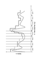
- FIG. 5 is a diagram for explaining the set current value.
- the horizontal axis in FIG. 5 indicates the rotation angle of the motor shaft in the stepping motor 13.
- FIG. 5 shows an example of returning from 180 degrees to 0 degrees via 0 degrees to 180 degrees.
- the vertical axis indicates the signal strength of the current value.
- the dotted line in FIG. 5 shows a virtual current value curve. This curve shows the current value when the current value at which the stepping motor 13 does not step out is set continuously.
- control unit 11 again divides the specific region into a plurality of regions, and determines the current value for each of the divided regions.
- control unit 11 determines an area to be repartitioned. For example, when one cycle is divided from the first area to the L-th area, the control unit 11 determines to re-divide the area near 180 degrees.
- control part 11 performs the process of step S301 to step S309 with respect to the area
- one cycle in step S301 is a re-segmented area.
- FIG. 6 is a diagram for explaining a specific example of re-segmenting a region around 180 degrees.
- the control unit 11 divides the region near 180 degrees into three regions, and sets a current value for each of the categories.
- a method may be used in which continuous current values indicated by dotted lines shown in FIG. 5 are set from current values set in advance in each region, and are classified based on the gradient of the current values.
- a portion with a steep inclination may be configured to be classified in detail as compared with a portion with a gentle inclination.
- control unit 11 can set the current value in more detail, and the power consumption of the combination weighing device 1 itself can be reduced.
- control unit 11 determines that the current value set in the N1 region among the regions divided in step S301 and the current value set in the N2 region that is a region adjacent to the N1 region. Based on this, an area related to re-segmentation may be determined.
- control unit 11 when the difference between the current value set in the N1 region and the current value set in the N2 region is greater than a preset value, the control unit 11 performs the N1 region or the N2 region. Are determined as areas to be repartitioned.
- One aspect of the present invention is applicable to a weighing device that varies a control signal output to a drive unit in a hopper. Specifically, one aspect of the present invention is applicable to a weighing device that combines and measures snacks and the like.
Landscapes
- Engineering & Computer Science (AREA)
- Physics & Mathematics (AREA)
- General Physics & Mathematics (AREA)
- Power Engineering (AREA)
- Mechanical Engineering (AREA)
- Control Of Stepping Motors (AREA)
Abstract
計量装置(1)は、ゲート(5,8,10)を有し、当該ゲートを開閉することにより、外部から投入され、一時的に滞留させた被計量物を排出するホッパ(4,6,9)と、ゲートを開閉駆動させる駆動部(13,14,15)と、駆動部に対して出力する制御信号を可変させることにより駆動部を制御する制御部(11)と、を備え、制御部は、ゲートの開閉駆動中における駆動部の脱調を検出し、当該検出した脱調の有無に基づいて、駆動部に出力する制御信号を可変させる。
Description
本発明の一側面は、ホッパが有するゲートに対して出力する制御信号を可変する計量装置に関する。
特許文献1は、組合せ秤を開示する。この組合せ秤は、ホッパゲートを開閉駆動したときに、ステッピングモータのモータ軸に掛かるトルクを、トルク計測器を用いて予め計測する(例えば段落0036等を参照)。具体的には、ステッピングモータのモータ軸に掛かるトルクとステッピングモータの駆動電流との間における比例関係に基づき、ホッパゲートを全閉位置から全開位置まで開放動作させるのに最低限必要な駆動電流を計測し、全開位置から全閉位置まで閉止動作させるのに最低限必要な駆動電流を計測する(例えば段落0037から0042等を参照)。これにより、ステッピングモータの消費電力を低減している。
特許文献1は、上記のようにホッパ開閉に必要となるトルクに基づいて、ホッパにおけるゲートの駆動電流を設定する。そのため、ホッパゲート開閉に係るステッピングモータのモータ軸に対してトルク計測器を取り付ける必要がある。この方式を実現するためには、トルク計測器を取り付ける空間を確保するため、少なくともステッピングモータ周辺における設計を見直す必要がある。
そこで、本発明の一側面は、上記のようなトルク計測器を用いずとも、モータからの信号に基づいて駆動部の脱調有無を検出し、検出した結果により駆動部への制御信号を可変できる計量装置を提供することを目的とする。
本発明の一側面に係る計量装置は、ゲートを有し、当該ゲートを開閉することにより、外部から投入され、一時的に滞留させた被計量物を排出するホッパと、ゲートを開閉駆動させる駆動部と、駆動部に対して出力する制御信号を可変させることにより駆動部を制御する制御部と、を備え、制御部は、ゲートの開閉駆動中における駆動部の脱調を検出し、当該検出した脱調の有無に基づいて、駆動部に出力する制御信号を可変させる。
本発明の一側面は、トルク計測器を用いずとも、モータからの信号に基づいて駆動部の脱調有無を検出し、検出した結果により駆動部への制御信号を可変できる計量装置を提供することを目的とする。
以下、適宜図面を参照しながら、一実施形態を詳細に説明する。但し、必要以上に詳細な説明は省略する場合がある。例えば、既によく知られた事項の詳細説明や実質的に同一の構成に対する重複説明を省略する場合がある。これは、以下の説明が不必要に冗長になるのを避け、当業者の理解を容易にするためである。
なお、発明者らは、当業者が本発明の一側面に係る一実施形態を十分に理解するために添付図面及び以下の説明を提供するのであって、これらによって特許請求の範囲に記載の主題を限定することを意図していない。
以下、図1~図4を用いて、一実施形態を説明する。図1は、一実施形態における組合計量装置の全体の概要を説明するための図である。図1に示されるように、一実施形態における組合計量装置(計量装置)1は、供給装置100から被計量物(図1においてはMと表記)を受け取る。そして、組合計量装置1は、受け取った被計量物について組合せ計量する。
ここで、被計量物は例えばスナック等の食品等であっても構わないし、ナット又はボルト等の金属部品であっても構わない。つまり、複数のホッパに対して所定量が供給された時に組合せて所望質量値を計量する対象であればどのような被計量物であってもよい。
ここで供給装置100は、使用者によって供給される被計量物を搬送し、分散部2に対して落下させる部材である。供給装置100の作用により、被計量物は組合計量装置1に投入される。一実施形態における供給装置100は、振動によって被計量物を搬送する装置でもよいし、ベルトコンベアによって搬送する装置でもよい。要するに、使用者によって供給される被計量物を分散部2まで搬送し、投入できる機能を有しておれば、どのような装置を利用してもよい。
以下、一実施形態における組合計量装置1の具体的な構成について説明する。一実施形態における組合計量装置1は、分散部2、供給トラフ3、プールホッパ4、ゲート5、計量ホッパ6、質量検出器7、ゲート8、ブースターホッパ9、ゲート10、制御部11及びステッピングモータ(駆動部)13,14,15を備える。
ここで、プールホッパ4、ゲート5、計量ホッパ6、質量検出器7、ゲート8、ブースターホッパ9及びゲート10は、それぞれ複数個存在する。本明細書では、それぞれを区別するため、プールホッパ4_iと表記する。ゲート5、計量ホッパ6、質量検出器7、ゲート8、ブースターホッパ9及びゲート10についても同様とする。また、iは、正の整数とする。例えば、プールホッパ4_1とは、複数個存在するプールホッパ4のうち1番目のプールホッパ4であることを示す。
分散部2は、供給装置100から落下する被計量物を供給トラフ3に向けて分散させる装置である。一実施形態における分散部2は、所定周波数にて連続して振動することにより、被計量物を供給トラフ3に向けて搬送する。なお、搬送に係る方式は振動に限定されず、被計量物を供給トラフ3に向けて搬送する機能を有していればどのような方式であってもよい。
供給トラフ3_iは、分散部2から供給される被計量物を、供給トラフ3_iのそれぞれの下流に対応して設けられたプールホッパ4_iに供給する部材である。
プールホッパ4_iは、供給トラフ3_iから供給される被計量物を一時的に滞留させる部材である。プールホッパ4_iは、ゲート5_iをそれぞれ有する。ゲート5_iが開閉動作することにより、プールホッパ4_iに滞留する被計量物は、ゲート5_iの下流に設けられた計量ホッパ6_iに排出される。
ここで、ゲート5_iのそれぞれは、ステッピングモータ13_iとそれぞれのリンク機構とを介して接続される。さらに、ステッピングモータ13_iは、制御部11と接続される。制御部11は、後述する方法によりステッピングモータ13_iのそれぞれに対して制御信号を出力する。ステッピングモータ13_iは、制御部11から出力される制御信号を受信すると、この制御信号に基づいて回転駆動を開始する。このようにステッピングモータ13_iが回転駆動することによりリンク機構が動作し、ゲート5_iが開閉動作する。このように構成することで、制御部11は、ゲート5_iの開閉動作を制御する。
具体的には、ステッピングモータ13_iにおけるモータ軸が0度から180度まで正回転することにより、ゲート5_iは閉状態から開状態に変化する。そして、ステッピングモータ13_iにおけるモータ軸が、180度から0度まで逆回転することにより、ゲート5_iは開状態から閉状態に変化する。
計量ホッパ6_iは、プールホッパ4_iが排出する被計量物を一時的に滞留させる部材である。計量ホッパ6_iは、質量検出器7_iと接続されている。被計量物が計量ホッパ6_iに投入された場合、質量検出器7_iに歪が発生する。そして、質量検出器7_iは、その歪に基づく信号に基づき計量ホッパ6_iに投入された被計量物の質量値を検出できる。
ここで、上記における質量検出器7_iは、具体的には、ロードセルで構成される。しかしながら、質量検出器7_iは、ロードセルに限定されず、音叉式センサを用いて、質量を検出してもよい。要するに、質量検出器7_iは、計量ホッパ6_iに投入された被計量物の質量を検出できれば、どのような構成の装置を利用してもよい。
ゲート8_iは、対応する計量ホッパ6_iのそれぞれに設けられ、計量ホッパ6_iに投入された被計量物を一時的に計量ホッパ6_i内に滞留させる部材である。このゲート8_iが開閉動作することにより、計量ホッパ6_iに滞留する被計量物は、ゲート8_iの下流に配置されるブースターホッパ9_iに排出される。
ここで、ゲート8_iのそれぞれは、ステッピングモータ14_iとそれぞれのリンク機構とを介して接続される。さらに、ステッピングモータ14_iは、制御部11と接続される。この制御部11は、後述する方法によりステッピングモータ14_iのそれぞれに対して制御信号を出力する。ステッピングモータ14_iは、制御部11から出力される制御信号を受信すると、この制御信号に基づいてモータ軸が回転駆動する。このように、ステッピングモータ14_iが回転駆動することによりリンク機構が動作し、ゲート8_iが開閉動作する。このように構成することで、制御部11はゲート8_iの開閉動作を制御する。
具体的には、ステッピングモータ14_iにおけるモータ軸が0度から180度まで正回転することにより、ゲート8_iは閉状態から開状態に変化する。そして、ステッピングモータ14_iにおけるモータ軸が、180度から0度まで逆回転することにより、ゲート8_iは開状態から閉状態に変化する。
ブースターホッパ9_iは、計量ホッパ6_iが排出する被計量物を一時的に滞留させる部材である。
ゲート10_iは、対応するブースターホッパ9_iのそれぞれに設けられ、ブースターホッパ9_iに投入された被計量物を一時的にブースターホッパ9_i内に滞留させるための部材である。このゲート10_iが開閉動作することにより、ブースターホッパ9_iに滞留する被計量物は、ゲート10_iの下流に配置される集合シュートに排出される。
ここで、ゲート10_iのそれぞれはステッピングモータ15_iとそれぞれのリンク機構とを介して接続される。さらに、ステッピングモータ15_iは、制御部11と接続される。この制御部11は、後述する方法によりステッピングモータ15_iのそれぞれに対して制御信号を出力する。ステッピングモータ15_iは、制御部11から出力される制御信号を受信すると、この制御信号に基づいて回転駆動する。このようにステッピングモータ15_iが回転駆動することによりリンク機構が動作し、ゲート10_iが開閉動作する。このように構成することで、制御部11はゲート10_iの開閉動作を制御する。
具体的には、ステッピングモータ15_iにおけるモータ軸が0度から180度まで正回転することにより、ゲート10_iは閉状態から開状態に変化する。そして、ステッピングモータ15_iにおけるモータ軸が、180度から0度まで逆回転することにより、ゲート10_iは開状態から閉状態に変化する。
図2は、一実施形態における組合計量装置1における電気的な結合を説明するためのブロック図である。一実施形態の組合計量装置1における各部材のうち少なくとも一部は、制御部11と接続され、その動作が制御される。そして、制御部11は、メモリ12、ステッピングモータ13_i、ステッピングモータ14_i及びステッピングモータ15_iと少なくとも電気的に接続される。
制御部11は、入力部(図示しない)を介して使用者から入力される情報に基づき、メモリ12に格納される制御用プログラムに従って組合計量装置1が有する各部材のうち少なくとも一部を制御する。
具体的には、制御部11は、ステッピングモータ13_i、ステッピングモータ14_i及びステッピングモータ15_iに対して制御信号を出力する。
例えば、制御部11は、ステッピングモータ13_i、ステッピングモータ14_i及びステッピングモータ15_iに流れる電流値を制御する場合、ステッピングモータ13_i、ステッピングモータ14_i及びステッピングモータ15_iに対して、所望の電流値に対応する電圧値を印加する。要するに、制御部11は、ステッピングモータ13_i、ステッピングモータ14_i及びステッピングモータ15_iに対して、所定の電圧値をパルス列として、間歇的に印加することにより、ステッピングモータ13_i、ステッピングモータ14_i及びステッピングモータ15_iに流れる電流値を制御する。
この場合、制御部11は、時間的にパルス幅を変更しながら直流電圧をステッピングモータ13_i、ステッピングモータ14_i及びステッピングモータ15_iに印加する。上記構成の場合、制御部11が制御する値は電流値となるが、ステッピングモータ13_i、ステッピングモータ14_i及びステッピングモータ15_iのそれぞれに対して出力する制御信号は電圧値となる。
なお、制御部11からステッピングモータ13_i、ステッピングモータ14_i及びステッピングモータ15_iのそれぞれに電圧値を出力する方法は、上記のような一定の電圧値をパルス列として間歇的に出力する方法に限定されず、ステッピングモータ13_i、ステッピングモータ14_i及びステッピングモータ15_iに対して出力する電圧値を時間的に可変させる方法でもよい。
また、制御部11は、ステッピングモータ13_i、ステッピングモータ14_i及びステッピングモータ15_iのそれぞれについて脱調の有無を検出する。
具体的には、制御部11は、ステッピングモータ13_i、ステッピングモータ14_i及びステッピングモータ15_iのそれぞれに対して制御信号を出力してから、ステッピングモータ13_i、ステッピングモータ14_i及びステッピングモータ15_iのそれぞれから信号を受信するまでの時間を計測している。予め設定される時間範囲内にステッピングモータ13_i、ステッピングモータ14_i及びステッピングモータ15_iのそれぞれから信号を受信した場合、制御部11は、ステッピングモータ13_i、ステッピングモータ14_i及びステッピングモータ15_iのそれぞれについて「脱調無し」と判断する。一方、予め設定される時間範囲にステッピングモータ13_i、ステッピングモータ14_i及びステッピングモータ15_iのそれぞれから信号を受信しない場合、ステッピングモータ13_i、ステッピングモータ14_i及びステッピングモータ15_iのそれぞれについて制御部11は「脱調有り」と判断する。
上記において制御部11は、ステッピングモータ13_i、ステッピングモータ14_i及びステッピングモータ15_iのそれぞれに対して制御信号を出力してから、ステッピングモータ13_i、ステッピングモータ14_i及びステッピングモータ15_iのそれぞれから信号を受信するまでのパルス数をカウントすることにより、時間を計測する。
メモリ12は、組合計量装置1の動作に関連する情報を少なくとも蓄積する記憶部である。制御部11は、メモリ12に蓄積される情報を読み出し処理することにより、目的の動作を実行する。
ステッピングモータ13は、ゲート5を開閉駆動させる駆動部である。ステッピングモータ13は、制御部11からの制御信号に基づき、モータ軸周りにトルクを発生させる。そして、発生したトルクの作用により、ステッピングモータ13は、ステッピングモータ13とゲート5とを接続するリンク機構を稼働させる。これにより、ステッピングモータ13は、ゲート5を開閉駆動させる。
さらに、ステッピングモータ13は、モータ軸が所定角度回転した場合、当該所定角度回転したことを示す信号を制御部11に出力する。具体的には、ステッピングモータ13は、フォトインタラプタを有する。そして、ステッピングモータ13のモータ軸が所定角度回転した場合、フォトインタラプタのスリットは塞がれるように構成されている。フォトインタラプタのスリットが塞がれた場合、フォトインタラプタから制御部11に対して信号が出力される。
なお、上記の構成に限定されず、ステッピングモータ13は、制御部11に対して、モータ軸が駆動する際の回転方向、回転位置又は回転速度を示す駆動情報を出力する構成にしてもよい。この駆動情報は、ステッピングモータ13にエンコーダが取り付けられている場合、そのエンコーダから出力される情報となる。
ステッピングモータ14は、ゲート8を開閉駆動させる駆動部である。ステッピングモータ14は、制御部11からの制御信号に基づき、モータ軸周りにトルクを発生させる。そして、発生したトルクの作用により、ステッピングモータ14は、ステッピングモータ14とゲート8とを接続するリンク機構を稼働させる。これにより、ステッピングモータ14は、ゲート8を開閉駆動させる。
さらに、ステッピングモータ13における構成と同様に、ステッピングモータ14はフォトインタラプタを有している。このフォトインタラプタのスリットが塞がれた場合、当該フォトインタラプタは、制御部11に対して信号を出力する。
ステッピングモータ15は、ゲート10を開閉駆動させる駆動部である。ステッピングモータ15は、制御部11からの制御信号に基づき、モータ軸周りにトルクを発生させる。そして、発生したトルクの作用により、ステッピングモータ15は、ステッピングモータ15とゲート10とを接続するリンク機構を稼働させる。これにより、ステッピングモータ15は、ゲート10を開閉駆動させる。
さらに、ステッピングモータ13における構成と同様に、ステッピングモータ15はフォトインタラプタを有している。このフォトインタラプタのスリットが塞がれた場合、当該フォトインタラプタは、制御部11に対して信号を出力する。
以下、図面を参照しながら制御部11における制御信号の生成動作について説明する。ここで、以下説明の便宜上、ステッピングモータ13_i、ステッピングモータ14_i及びステッピングモータ15_iのそれぞれに流れる電流値を制御するため、制御部11はステッピングモータ13_i、ステッピングモータ14_i及びステッピングモータ15_iのそれぞれに対して可変的に電圧値を印加する。
また、ステッピングモータ14_i及びステッピングモータ15_iに対して出力する電圧値の生成方法は、ステッピングモータ13_iに対して電圧値を生成する方法と同じである。そのため、ステッピングモータ13_iに対して電圧値を生成する方法を主に説明し、ステッピングモータ14_i及びステッピングモータ15_iに対して出力する電圧値の生成方法についてはその説明を省略する。
制御信号の生成動作について簡略的に説明すると、制御部11は、ゲート5の開閉駆動中に、ステッピングモータ13の脱調の有無を検出する。そして、制御部11は、脱調を検出した場合、脱調時の電流値を基準として新たな電流値を設定する。
ここで、ステッピングモータ13におけるフォトインタラプタから制御部11に対して出力される信号に基づき、制御部11はステッピングモータ13における脱調を検出する。例えば、メモリ12は、制御部11がステッピングモータ13に対して電圧値を出力してから、ステッピングモータ13のフォトインタラプタから信号を受信するまでの時間に関する値を有している。例えば、メモリ12は1秒から1.5秒という時間範囲に関する値を有する。そして、制御部11は、実際にステッピングモータ13に対して電圧値を印加してからステッピングモータ13のフォトインタラプタから信号を受信するまでの時間(以下、受信時間と称す)が、上記時間範囲に含まれる場合、「脱調無し」と検出する。つまり、電圧値を出力してから1.2秒後にフォトインタラプタからの信号を受信した場合、制御部11は「脱調無し」と検出する。一方、上記受信時間が上記時間範囲に含まれない場合、制御部11は「脱調有り」と検出する。つまり、電圧値を出力してから2秒後にフォトインタラプタからの信号を受信した場合、制御部11は「脱調有り」と検出する。
なお、脱調の検出は上記の方法に限定されず、脱調を検出できる方法であればどのような方法を利用してもよい。
図3は、初期設定として、制御部11において脱調時の電流値を基準として新たな電流値を設定する際のフローチャートである。
制御部11は、ゲート5が閉状態から開状態となり再度閉状態となるまでを1サイクルとする場合、この1サイクルを第1領域から第L領域に区分する(ステップS301)。例えば、制御部11は、1サイクルの開閉動作を、22.5度毎に区分する。なお、上記では1サイクルを22.5度毎に区分する構成を例に挙げて説明した。しかし、1サイクルを5又は20のような他の区分数に区分する構成であってもよい。
次に、制御部11は、初期設定として変数Nを1と設定する(ステップS302)。
制御部11は、第1領域から第L領域のそれぞれにおいて、ステッピングモータ13に流れる電流値が、ステッピングモータ13で流すことが可能な最大の電流値となるように電圧値を設定する(ステップS303)。
そして、制御部11は、ステップS303で設定した電圧値をステッピングモータ13に印加する(ステップS304)。なお、ステップS306において第N領域の電流値が下げられている場合、制御部11は下げた後の電流値に対応する電圧値を印加する。
制御部11は、ステッピングモータ13に対して電圧値を印加した後、第N領域においてステッピングモータ13が脱調したか否かを判断する(ステップS305)。ステッピングモータ13が脱調したと判断する場合(S305:No)、制御部11はステップS307に移行する。一方、第N領域においてステッピングモータ13が脱調していないと判断する場合(S305:Yes)、制御部11はステップS306に移行する。
ステッピングモータ13が脱調していないと判断する場合、制御部11は、第N領域において流れる電流値を、前回第N領域において流した電流値よりも小さく再設定する(ステップS306)。そして、再設定した電流値に基づき、制御部11はステップS304に戻る。なお、電流値を小さくする方法はどのような方法でもよく、例えば前回設定している電流値の90%に設定することができる。
一方、ステッピングモータ13が脱調したと判断する場合、制御部11は、第N領域においてステッピングモータ13に流す電流値を決定する(ステップS307)。説明の便宜上、ステッピングモータ13が脱調した際の電流値を限界電流値と称す。具体的には、制御部11は、ステップS304にて第N領域における限界電流値よりも大きな電流値を、実際の第N領域の電流値として決定する。
なお、ステップS304にて第N領域において流れた電流値よりも大きな電流値とする場合、例えば限界電流値よりも約10%大きな電流値とすることが考えられる。別の言い方とすると、制御部11は、ステッピングモータ13に印加する電圧値を、第N領域における限界電流値によりステッピングモータ13が発生させるトルクよりも強いトルクが発生する電圧値に変更する。
次に、制御部11は、NとLとが等しいか否かを判断する(ステップS308)。NとLとが等しくない場合(S308:No)、制御部11はステップS309に移行する。一方、NとLとが等しい場合(S308:Yes)、制御部11はそのまま動作を終了する。
NとLとが等しくない場合、すべての領域において電流値が決定されていない(ステップS309)。そのため、制御部11はNを1つだけインクリメントし、ステップS303移行の動作をインクリメント後のNについて実施する。
なお、ステップS303においてステッピングモータ13に流れる電流値は出力可能な最大の電流値として説明した。しかし、既に実際の電流値が決定されている領域では、制御部11はその決定された電流値に基づく電圧値を印加してもよい。このように制御することにより、電流値を設定する初期設定時においても組合計量装置1における消費電力を削減できる。
制御部11は、図3に示すフローチャートに従って、第1領域から第L領域のそれぞれにおける電流値を決定する。以降の動作において、制御部11は、それぞれの領域において決定した電流値に基づく電圧値を印加する。
図4は、図3に示すフローチャートで決定した電流値を用いて動作させている際、ステッピングモータ13が脱調した際に電流値を補正する動作を説明するためのフローチャートである。
ゲート5を開閉動作させる場合、第1領域から第L領域のそれぞれについてステップS307において決定した電流値に基づいて、制御部11はステッピングモータ13に電圧値を印加する(ステップS401)。
このとき、ステッピングモータ13におけるフォトインタラプタから出力される信号に基づき、第1領域から第L領域のそれぞれの区間で、制御部11はステッピングモータ13における脱調の有無を判断する(ステップS402)。ステッピングモータ13において脱調が発生した場合(S402:Yes)、ステップS403に移行する。一方、ステッピングモータ13において脱調が発生しない場合(S402:No)、制御部11はステップS307で設定した電流値を変更せず(ステップS404)、そのままステッピングモータ13に対して設定した電流値に対応する電圧値を印加する(ステップS405)。
ステップS402においてステッピングモータ13で脱調が発生したと判断する場合、制御部11は脱調が発生した領域を特定する。そして、制御部11は、脱調が発生した領域について、脱調時に印加した電圧値に基づき、当該領域に対する新たな電流値を設定する(ステップS403)。具体的には、制御部11は、ステップS402にて脱調に係る領域において出力した電圧値に対応する限界電流値よりも大きな電流値を、脱調が発生した領域の電流値として再設定する。そして、制御部11は、ステッピングモータ13に対して、ステップS402で再設定した電流値に対応する電圧値を印加する(ステップS405)。
制御部11は、図3に示すフローチャートにて区分した領域のそれぞれにおいてステッピングモータ13に対して流す電流値を決定する。決定した電流値を利用する場合であっても、リンク機構の劣化等によりステッピングモータ13は脱調する。そこで、図4に示すフローチャートに規定する動作を実施することにより、制御部11はステッピングモータ13に脱調が発生した場合であっても都度電流値を修正できる。
要するに、一度電流値を決定した後、その電流値に基づき組合計量する場合であっても、上記のように制御することで各領域にて流れる電流値を脱調しない電流値に補正できる。
なお、組合計量装置1は複数のゲートを有する。上記のように領域毎に電流値を設定する場合、複数のゲートのそれぞれについて設定することが考えられる。
しかし、実際の制御を鑑みた場合、複数のゲートで共通の設定情報を有することが考えられる。この場合、複数のゲートのうち特定のゲートのみで脱調が発生した場合であっても、すべてのゲートの電流値が一律変更される構成となる。
以上のように、一実施形態において、組合計量装置1は、ゲート5を有し、当該ゲート5が開閉することにより、外部から投入される被計量物を一時的に滞留させるプールホッパ4と、ゲート5を開閉駆動させるステッピングモータ13と、ステッピングモータ15に対して出力する制御信号を可変させ、ステッピングモータ13を制御する制御部11と、を備える。
そして、制御部11は、ゲート5の開閉駆動中におけるステッピングモータ13の脱調を検出し、当該検出した脱調の有無に基づいて、ステッピングモータ13に出力する制御信号を可変させる。
これにより、制御部11はステッピングモータ13における脱調をトリガーとしてステッピングモータ13に出力する制御信号を可変できる。そのため、時間的にホッパ開閉に必要なトルクが変化し、ステッピングモータが脱調するような場合であっても、時間的に次のホッパ開閉動作では脱調を回避できる。
また、制御部11は、ステッピングモータ13に対し、所定時刻において第1制御信号を出力した際、ゲート5の開閉駆動中におけるステッピングモータ15の脱調有無を判断してもよい。判断の結果、所定時刻において第1制御信号を出力した際にステッピングモータ15が脱調する場合、所定時刻で出力する制御信号を、第1制御信号によりゲート5の開閉駆動中に発生する駆動力よりも強い駆動力が発生する第2制御信号に変更してもよい。
上記において、所定時刻における出力する第1制御信号とは、例えば第1領域に属する時刻において出力する電流値を意味する。
これにより、制御部11は脱調時における制御信号を基準として新たな制御信号を設定できる。その際、脱調時における制御信号により発生する駆動力よりも強い駆動力が発生する制御信号に変更できる。そのため、例えば、時間的に次にホッパを開閉駆動した際には、ステッピングモータにおける脱調を回避できる。
また、制御部11は、所定の時間間隔で複数に区切られた時間領域、つまり上記における第1領域から第L領域ごとに、ゲート5の開閉駆動中におけるステッピングモータ13の脱調を検出し、当該検出した脱調の有無に基づいて、ステッピングモータ13に出力する制御信号を設定してもよい。
以上、一実施形態について説明したが、本発明は、上記実施形態に限られず、発明の趣旨を逸脱しない範囲で種々の変更が可能である。例えば、上記におけるステップS301において、制御部11は1サイクルを第1領域から第L領域に区分する。
ここで、区分する間隔が大きければ大きいほど、区分した領域のうち少なくとも一部で脱調が発生しない最小の電流値と、実際に決定した当該区分した領域における電流値との差が大きくなる。
図5は、設定した電流値を説明するための図である。図5における横軸はステッピングモータ13におけるモータ軸の回転角度を示す。図5では0度から180度を経由し、180度から0度に戻る例を示す。また、縦軸は電流値の信号強度を示す。さらに、図5における点線は、仮想的な電流値曲線を示す。この曲線は、ステッピングモータ13が脱調しない電流値を連続的に設定した時の電流値を示す。
例えば、図5に示すように1サイクルを22.5度毎に区分し、それぞれの領域で電流値が設定されているとする。ここで、図5における180度付近の領域に着目する。この領域に設定される電流値と、図5に示す点線と比較した場合、当該領域の開始時及び当該領域の終了時では、実際に設定される電流値と点線が示す電流値の差が大きい。
そこで、制御部11は、複数の領域ごとに電流値を決定した後、特定の領域を再度複数の領域に区分し、区分した領域のそれぞれについて電流値を決定する。
具体的には、制御部11は、再区分する領域を決定する。例えば、1サイクルを第1領域から第L領域に区分している場合、制御部11は180度付近の領域を再区分すると決定する。
そして、制御部11は、再区分した領域に対して、ステップS301からステップS309の処理をする。この場合、ステップS301における1サイクルは、再区分した領域となる。
図6は180度付近の領域を再区分する具体例を説明するための図である。具体的には、制御部11は、180度付近の領域を3つの領域に区分し、その区分ごとに電流値を設定する。再区分する場合、等間隔に区分する必要はない。例えば予め各領域にて設定される電流値から図5に示す点線の連続的な電流値を設定し、その電流値の傾きに基づいて区分する方法でもよい。つまり、傾きが急な部分については、傾きが緩やかな部分と比較して詳細に区分するように構成してもよい。
上記のように実施することにより、制御部11はより詳細に電流値を設定でき、組合計量装置1自体の消費電力を低減できる。
なお、制御部11は、ステップS301において複数に区切られた領域のうち第N1領域で設定される電流値と、当該第N1領域と隣接する領域である第N2領域で設定される電流値とに基づいて、再区分に係る領域を決定してもよい。
具体的には、制御部11は、第N1領域で設定される電流値と第N2領域で設定される電流値との差が予め設定される値よりも大きい場合、第N1領域又は第N2領域のうち少なくともいずれか一方を再区分する領域として決定する。
以上のように、本発明の一側面の例示として、上記一実施形態を説明した。そのために、添付図面及び詳細な説明を提供した。したがって、添付図面及び詳細な説明に記載された構成要素の中には、課題解決のために必須な構成要素だけでなく、上記技術を例示するために、課題解決のためには必須でない構成要素も含まれ得る。そのため、それらの必須ではない構成要素が添付図面や詳細な説明に記載されていることをもって、直ちに、それらの必須ではない構成要素が必須であるとの認定をするべきではない。
また、上述の一実施形態又は変形例は、本発明の一側面における技術を例示するための例であるから、特許請求の範囲又はその均等の範囲において種々の変更、置き換え、付加、省略などを行うことができる。
本発明の一側面は、ホッパにおける駆動部に出力する制御信号を可変させる計量装置に適用可能である。具体的には、スナック等を組合せ計量する計量装置などに、本発明の一側面は適用可能である。
1…組合計量装置(計量装置)、2…分散部、3…供給トラフ、4…プールホッパ、5…ゲート、6…計量ホッパ、7…質量検出器、8…ゲート、9…ブースターホッパ、10…ゲート、11…制御部、12…メモリ、13,14,15…ステッピングモータ(駆動部)。
Claims (5)
- ゲートを有し、当該ゲートを開閉することにより、外部から投入され、一時的に滞留させた被計量物を排出するホッパと、
前記ゲートを開閉駆動させる駆動部と、
前記駆動部に対して出力する制御信号を可変させることにより前記駆動部を制御する制御部と、を備え、
前記制御部は、前記ゲートの開閉駆動中における前記駆動部の脱調を検出し、当該検出した脱調の有無に基づいて、前記駆動部に出力する制御信号を可変させる、計量装置。 - 前記制御部は、
前記駆動部に対し、所定時刻において第1制御信号を出力した際、前記ゲートの開閉駆動中における前記駆動部の脱調の有無を判断し、
前記判断の結果、前記所定時刻において前記第1制御信号を出力した際に前記駆動部が脱調する場合、前記所定時刻で出力する制御信号を、前記第1制御信号により前記ゲートの開閉駆動中に発生する駆動力よりも強い駆動力が発生する第2制御信号に変更する、請求項1に記載の計量装置。 - 前記制御部は、
所定の時間間隔で複数に区切られた時間領域ごとに、前記ゲートの開閉駆動中における前記駆動部の脱調を検出し、当該検出した脱調の有無に基づいて、前記駆動部に出力する制御信号を設定する、請求項1に記載の計量装置。 - 前記制御部は、複数に区切られた時間領域のうち第N時間領域で設定される制御信号と、当該第N時間領域と隣接する時間領域である第M時間領域で設定される制御信号とに基づいて、前記第N時間領域を複数の時間領域に再度区切り、当該再度区切られた時間領域ごとに、前記ゲートの開閉駆動中における前記駆動部の脱調を検出し、当該検出した脱調の有無に基づいて、前記駆動部に出力する制御信号を設定する、請求項3に記載の計量装置。
- 前記制御部は、第N時間領域で設定される制御信号と、第M時間領域で設定される制御信号との差が予め設定される値よりも大きい場合、前記第N時間領域を複数の時間領域に再度区切り、当該再度区切られた時間領域ごとに、前記ゲートの開閉駆動中における前記駆動部の脱調を検出し、当該検出した脱調の有無に基づいて、前記駆動部に出力する制御信号を設定する、請求項4に記載の計量装置。
Applications Claiming Priority (2)
| Application Number | Priority Date | Filing Date | Title |
|---|---|---|---|
| JP2015133163A JP2018138869A (ja) | 2015-07-02 | 2015-07-02 | 計量装置 |
| JP2015-133163 | 2015-07-02 |
Publications (1)
| Publication Number | Publication Date |
|---|---|
| WO2017002810A1 true WO2017002810A1 (ja) | 2017-01-05 |
Family
ID=57608490
Family Applications (1)
| Application Number | Title | Priority Date | Filing Date |
|---|---|---|---|
| PCT/JP2016/069147 Ceased WO2017002810A1 (ja) | 2015-07-02 | 2016-06-28 | 計量装置 |
Country Status (2)
| Country | Link |
|---|---|
| JP (1) | JP2018138869A (ja) |
| WO (1) | WO2017002810A1 (ja) |
Families Citing this family (1)
| Publication number | Priority date | Publication date | Assignee | Title |
|---|---|---|---|---|
| JP7315096B2 (ja) | 2020-04-30 | 2023-07-26 | 株式会社島津製作所 | 分析装置 |
Citations (3)
| Publication number | Priority date | Publication date | Assignee | Title |
|---|---|---|---|---|
| JPH04156857A (ja) * | 1990-10-19 | 1992-05-29 | Sharp Corp | 輸液ポンプ用ステッピングモータ制御装置 |
| JPH11215890A (ja) * | 1998-01-21 | 1999-08-06 | Toshiba Corp | モータ駆動制御装置とモータ駆動制御方法および画像形成装置とその制御方法 |
| JP2011064489A (ja) * | 2009-09-15 | 2011-03-31 | Yamato Scale Co Ltd | 組合せ秤及び組合せ秤におけるホッパゲートの駆動方法 |
-
2015
- 2015-07-02 JP JP2015133163A patent/JP2018138869A/ja active Pending
-
2016
- 2016-06-28 WO PCT/JP2016/069147 patent/WO2017002810A1/ja not_active Ceased
Patent Citations (3)
| Publication number | Priority date | Publication date | Assignee | Title |
|---|---|---|---|---|
| JPH04156857A (ja) * | 1990-10-19 | 1992-05-29 | Sharp Corp | 輸液ポンプ用ステッピングモータ制御装置 |
| JPH11215890A (ja) * | 1998-01-21 | 1999-08-06 | Toshiba Corp | モータ駆動制御装置とモータ駆動制御方法および画像形成装置とその制御方法 |
| JP2011064489A (ja) * | 2009-09-15 | 2011-03-31 | Yamato Scale Co Ltd | 組合せ秤及び組合せ秤におけるホッパゲートの駆動方法 |
Also Published As
| Publication number | Publication date |
|---|---|
| JP2018138869A (ja) | 2018-09-06 |
Similar Documents
| Publication | Publication Date | Title |
|---|---|---|
| US9829877B2 (en) | Servo control apparatus having function of displaying adjustment state in online automatic adjustment to control system | |
| WO2012077768A1 (ja) | モータ制御回路 | |
| EP3617668B1 (en) | Combination weigher | |
| JP2018138869A (ja) | 計量装置 | |
| JPH0658243B2 (ja) | 特にばら荷用の差動配量秤を調整する方法及びこの方法を実行する差動配量秤 | |
| JPWO2018199320A1 (ja) | 計量装置 | |
| WO2014110064A1 (en) | Multi-protocol driver slew rate calibration system for calibrating slew rate control signal values | |
| US9405281B2 (en) | Load torque estimation apparatus, image forming apparatus, load torque estimation method and non-transitory computer-readable information recording medium | |
| JP5366730B2 (ja) | 組合せ秤及び組合せ秤におけるホッパゲートの駆動方法 | |
| JP5316961B2 (ja) | 原料秤量制御装置 | |
| JP5638228B2 (ja) | 定量供給装置 | |
| JP6529167B2 (ja) | 組合せ計量装置 | |
| US20140176167A1 (en) | Semiconductor apparatus | |
| US7002082B2 (en) | Combinational weighing device | |
| CN109959436B (zh) | 物料称量的控制方法、装置及物料称量系统 | |
| JP2011013003A (ja) | 組合せ秤 | |
| JP6022249B2 (ja) | 回転式重量選別装置 | |
| CN102902175A (zh) | 图像形成装置和旋转多面镜的旋转相位差调整方法 | |
| US5973532A (en) | Circuit arrangement for generating two signals staggered in time from a clock signal and for measuring their time stagger | |
| JP5425362B2 (ja) | スキュー補正システムおよびスキュー補正システムを制御する方法 | |
| US20140159633A1 (en) | Motor control apparatus and method | |
| JP7191971B2 (ja) | 検体搬送装置、システム、及び方法 | |
| EP3731403A1 (en) | Synchronous control device | |
| US20240264195A1 (en) | Ultrasonic time measurement device, and ultrasonic time measurement method | |
| JP2013167594A (ja) | 組合せ秤におけるホッパゲートの駆動方法及び組合せ秤 |
Legal Events
| Date | Code | Title | Description |
|---|---|---|---|
| 121 | Ep: the epo has been informed by wipo that ep was designated in this application |
Ref document number: 16817918 Country of ref document: EP Kind code of ref document: A1 |
|
| NENP | Non-entry into the national phase |
Ref country code: DE |
|
| 122 | Ep: pct application non-entry in european phase |
Ref document number: 16817918 Country of ref document: EP Kind code of ref document: A1 |
|
| NENP | Non-entry into the national phase |
Ref country code: JP |